1
User Manual
59300028
31.5.2006
Broadband Cable Networks
AC69x0
Rev.007
4(38)
In AC8000 platform a shroud is attached to the lid, to shield the electronics from
electromagnetic interference. The silicon elastomer must be attached to area
provided in the shroud.
Connectors
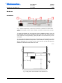
The transponder has an RJ-45 service port (fig.1 pos.1) with RS-485
connection, which can be used for local configuration with a PC and DVX021
cable or DVX012 programming unit.
Service port connector (shielded RJ-45 socket)
Pin Signal
Description
1
RS-485 +
DVX bus 38400 bps
2
RS-485 DVX bus 38400 bps
3
NC
Not connected
4
NC
Not connected
5
NC
Not connected
6
NC
Do not connect
7
+12 V
Output for aux equipment (unfused)
8
GND
Ground
I/O
I/O
I/O
O
-
Indicators
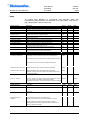
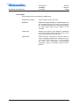
Depending on the unit the two leds on the front panel are labeled as STATION
and MODEM (AC6910 and AC6950) or ALSC (AC6940). The following table
further describes these indicators. During the power-up sequence both leds will
display yellow light for a short period of time to indicate that leds are functional.
See also the ‘Flags’ chapter for details of LED usage.
STATION LED
██████████ yellow
Description
No alarms or warnings (other than modem
related).
At least one warning, no alarms.
██████████ red
At least one alarm.
MODEM LED (AC6910
and AC6950)
Description
██████████ dark
Scanning for a communication channel
██████████ green (blinking)
Communication channel found.
██████████
green
Communication is OK, receiver level OK.
██████████
yellow
Communication is OK, receiver level not OK.
██████████
red
Internal error.
██████████ green
ALSC LED (AC6940)
Description
██████████
dark
ALSC off.
██████████
green
ALSC OK.
██████████
yellow
ALSC is saturated or on 1 pilot only.
██████████
red
All pilots are missing.