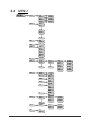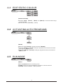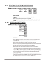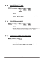
1
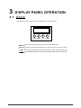
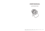
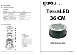
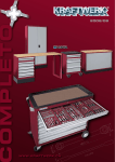
USER MANUAL
Please Read Over This Manual Before Operating The Light Fixtur e
T
ABLE OF CONTENTS
PART 1 PRODUCT (GENERAL)....................................................1.
1.1--PRODUCT INTRODUCTION.........................................................1.
1.2 -- PRODUCT FEATURES .................................................................1.
1.3 -- TECHNICAL SPECIFICATIONS .....................................................2.
1.4 -- PHOTOMETRIC DATA ..................................................................3.
1.5 -- SAFETY WARNING ......................................................................4.
PART 2 INSTALLATION...............................................................5.
2.1--MOUNTING...................................................................................5.
2.2--POWER CONNECTION..................................................................5.
2.3--SETTING UP WITH A DMX512 CONTROLLER.................................6.
2.3-1--DMX512 ADDRESSING WITHOUT ID ADDRESSING......................................6.
2.3-2--DMX512 ADDRESSING WITH ID ADDRESS..................................................6.
PART 3 DISPLAY PANEL OPERATION.........................................8.
3.1--BASIC..........................................................................................8.
3.2--MENU..........................................................................................9.
3.3--EDIT STATIC COLOUR............................................................... 10.
3.4--ACTIVATING AUTO PROGRAMS.................................................10.
3.5--RUN MODE................................................................................ 10.
3.6--DMX512 SETTINGS....................................................................11.
3.7--PERSONALITY........................................................................... 11.
3.8--ID ADDRESS.............................................................................. 11.
3.9--EDITING CUSTOM PROGRAMS ................................................ 12.
3.10--SPECIAL SETTINGS.................................................................12.
3.11-- WHITES SETTING ....................................................................13.
3.12-- WHITES BALANCE .................................................................. 13.
3.13--A CTIVATE THE PASSWORD .................................................... 13.
PART 4 USING A DMX512 CONTROLLER....................................14.
4.1--BASIC ADDRESSING.................................................................14.
4.2--CHANNEL ASSIGNMENT............................................................14.
4.3--BASIC INSTRUCTIONS FOR DMX512 OPERATION......................19.
PART 5 APPENDIX......................................................................20.
5.1--TROUBLE SHOOTING............................................................... 20.
5.2--MAINTENANCE......................................................................... 21.
1
PRODUCT (GENERAL)
1.1
PRODUCT INTRODUCTION
This product is designed for indoor or outdoor use. Suitable applications include wash or
effect lighting for architectural, stage, theatre or road show applications. Direct input of
DMX512 signal allows the units to be controlled from any DMX512 controller. This product
can be operated as a single unit or in multiple units for large applications.
1.2
PRODUCT FEATURES
LED F IXTURE
* DIM1~4
* DV:NTSC\PAL
* RGBW Dimmer 0-100%
* Strobe
* Built-in automatic programs
* Upload custom parameters to slave fixtures
* LED display
* Display control 'lock-out'
* Direct DMX512 input
* Independent ID address
* Different white colors setting
* 'Over-heat' protection
1
ÓÉ Foxit PDF Editor ±à¼°æȨËùÓÐ (c) by Foxit Software Company, 2004
½öÓÃÓÚÆÀ¹À¡£
1.3
TECHNICAL SPECIFICATIONS
LED M ODULE
LED MODULE:
Voltage
100~250V...50/60Hz
Rated Power
200W
54pcs (14 x RED / 14 x GREEN / 14 x BLUE/ 12 x WHITE)
LED/Unit
Output/LED
3W
Environment Temperature -20℃~40℃
fan
Cooling
Dimensions
270 x 270 x 490mm
Weight
3.2Kg
2
PHOTOMETRIC DATA
PHOTOMETRIC D ATA
RED
3931
1010
482
274
2
4
6
8
6130
1700
776
450
2
4
6
8
1360
256
120
68
2
4
6
8
186 LUX
15°
3
2
1
0
1
2
3
10Distance(m)
GREEN
304 LUX
15°
3
2
1
0
1
2
3
10Distance(m)
BLUE
46 LUX
15°
3
2
1
0
1
2
3
10Distance(m)
WHITE
4613
1204
552
326
2
4
6
8
11340
2885
1285
765
2
4
6
8
16300
4000
1900
1122
2
4
6
8
230 LUX
15°
3
2
1
0
1
2
3
10Distance(m)
RGB
530 LUX
15°
3
2
1
0
1
2
3
10Distance(m)
RGB+WHITE
3
2
1
0
1
2
3
752 LUX
15°
1.4
3
10Distance(m)
1.5
SAFETY WARNING
IMPORTANT
【ALWAYS READ THE USER MANUAL BEFORE OPERATION. 】
【PLEASE CONFIRM THAT THE POWER SUPPLY STATED ON THE
PRODUCT IS THE SAME AS THE MAINS POWER SUPPLY IN YOUR
AREA.】
● This
product must be installed by a qualified professional.
operate the equipment as described in the user manual.
● A minimum distance of 0.5m must be maintained between the equipment and
combustible surface.
● The product must always be placed in a well ventilated area.
● Always make sure that the equipment is installed securely.
● DO NOT stand close to the equipment and stare directly into the LED light
source.
● Always disconnect the power supply before attempting and maintenance.
● Always make sure that the supporting structure is solid and can support the
combined weight of the products.
● The earth wire must always be connected to the ground.
● Do not touch the power cables if your hands are wet.
● Always
ATTENTION
● This
product left the place of manufacture in perfect condition. In order to
maintain this condition and for safe operation, the user must always follow the
instructions and safety warnings described in this user manual.
● Avoid shaking or strong impacts to any part of the equipment.
● Make sure that all parts of the equipment are kept clean and free of dust.
● Always make sure that the power connections are connected correct and
secure.
● If there is any malfunction of the equipment, contact your distributor
immediately.
● When transferring the product, it is advisable to use the original packaging in
which the product left the factory.
● Shields, lenses or ultraviolet screens shall be changed if they have become
damaged to such an extent that their effectiveness is impaired.
● The lamp (LED) shall be changed if it has become damaged or thermally
deformed.
4
ÓÉ Foxit PDF Editor ±à¼°æȨËùÓÐ (c) by Foxit Software Company, 2004
½öÓÃÓÚÆÀ¹À¡£
2
2.1
INSTALLATION
MOUNTING
HANGING
The fixture can be mounted in a hanging position
using the supporting bracket.
The bracket
should be secured to the mounting truss or
structure using a standard mounting clamp.
Please note that when hanging the unit a safety
cable should also be used.
UPRIGHT
The fixture can be mounted in an upright or
sitting position using the supporting brackets.
The LED MODULE can be mounted at any angle and in any
position. It is possible to further adjust the angle of the LED
MODULE using the two adjustment knobs located on the side of
the fixture.
2.2
POWER CONNECTIONS
@ 220V: 15 units may be connected in series
@120V: 7 units may be connected in series
Note:
1. As this fixture's DMX signal cable connection is Parallel connection, so if over 32 units to be
connected, then a DMX signal amplifier is needed.
2. If the signal cable is over 60m between the DMX512 controller and fixture or beween two
fixtures, then a DMX signal amplifier is needed as well.
5
2.3
SETTING UP WITH A DMX512
CONTROLLER
2.3-1 DMX512 ADDRESSING WITHOUT ID ADDRESSING
(STAG MODE)
● Connect
the DMX512 controller to the units in series.
unit has 11 DMX channels so the DMX Addresses should increase by increments of
11 (e.g. 1,12,23,34...)
●The ID address has not been set so therefore when using the controller CH11 must
be inactive ( CH11=0 ).
●It is also possible to deactivate ID address selecting【ID OFF】from the【Settings】menu.
on the fixture
● Each DMX Address may be used as many times as required.
● Any DMX address in the range from 001 to 512 may be used.
● Each
Example:
DMX Addr.1
DMX Addr.12
DMX Addr.23
............
DMX512
CONTROLLER
The figure above shows a simple DMX512
layout with the starting address of the first
unit set at 1, with the second set at 12 and
so on... (Note that when used in this way,
the CH11 ID function must be inactive (CH11=0))
2.3-2 DMX512 ADDRESSING WITH ID ADDRESS (STAG MODE)
● Connect
the DMX512 controller to the units in series
unit has 11 DMX channels so the DMX Addresses should increase by increments of
11 (e.g. 1,12,23,34...)
● Each DMX Address may be used as many times as required.
● Any DMX address in the range from 001 to 512 may be used.
● Each DMX address may carry up to 66 separate ID addresses.
● 【ID】should be set in the menu on each unit in ascending values
(i.e. 1,2,3...)
● 【ID On】should be set in the【Settings】menu on each unit.
● ID addresses are accessible from Ch9 on the DMX512 controller.
● Each
6
Example:
DMX Addr.1
ID Addr.1
DMX Addr.1
ID Addr.2
DMX Addr.1
ID Addr.3
DMX Addr.12
ID Addr.1
DMX Addr.12
ID Addr.2
DMX Addr.12
ID Addr.3
............
DMX512
CONTROLLER
The figure above shows a simple DMX layout
which has used three units at each DMX address.
The three units have different ID addresses which
allows the user to collectively control the whole
group of units at that DMX address by setting
CH11 to 0, or to control each unit independently by
first selecting the DMX address and then by using
CH11 to locate the target ID address.
7
3
3.1
DISPLAY PANEL OPERATION
BASIC
The LED fixture is mounted with a LCD display and 4 control buttons.
MENU ENTER
UP
DOWN
MENU
scroll through the main menu or return to the main menu
ENTER
enter the currently selected menu or confirm the current function value
scroll 'UP' through the menu list or increase the value of the current function
scroll 'DOWN' through the menu list or decrease the value of the current function
8
3.2
MENU
MENU
STAT
Red
Green
Blue
White
Strob
AUTO
AT.01
AT.02
(0~255)
(0~255)
(0~255)
(0~255)
(0~20)
AT.10
PR.01
PR.02
PR.10
RUN
DMX
SLAV
DMX
D(001~512)
PERS
STAG
Arc.1
Ar1.d
Arc.2
Ar2.d
Ar2.s
HSV
ID
ID(01~66)
EDIT
PR.01
PR.02
SC.01
SC.02
PR.10
SC.30
SET
UPLD
REST
ID
Red
Green
Blue
White
Strobe
Time
(0~255)
(0~255)
(0~255)
(0~255)
(0~20)
(0~255)
Fade
(0~255)
ON
OFF
ON
OFF
HIGH
NORM
Off
Dim1
Dim2
RGBW
POW
Dim
Dim3
Dim4
CAL1
DV
Dim4
NTSC
PAL
Dim4
WT01
WT02
Red
Green
Blue
White
(0~255)
(0~255)
(0~255)
(0~255)
Red
Green
Blue
(0~255)
(0~255)
(0~255)
WT11
CAL2
RGBW
KEY
ON
OFF
9
3.3
EDIT STATIC COLOUR
MENU
STAT
(0~255)
(0~255)
(0~255)
(0~255)
(0~20)
Red
Green
Blue
White
Strob
【STATIC COLOUR】
Combine 【Red】, 【Green】, 【Blue】 and 【White】 to create an infinite range
of colors (0-255)
● Set the value of the 【Strobe】 (0-20Hz)
●
3.4
ACTIVATING AUTO PROGRAMS
MENU
AUTO
AT.01
AT.02
AT.10
PR.01
PR.02
PR.10
【AUTO】
Select the target【AUTO】 program and press【ENTER】.
Programs【AT.01】to【AT.10】are fully pre-programmed and will not be altered
by changes in【EDIT 】mode.
● Programs 【PR.01】to【PR.10】are fully pre-programmed and can be edited in
【EDIT 】mode.
●
●
3.5
RUN MODE
MENU
RUN
DMX
SLAV
【RUN 】
Enter the【RUN 】mode to set working mode.
【DMX】 mode is for using the DMX512 controller to control the fixtures.
● 【SLAV】 mode is for Master -- Slave operation.
●
●
10
3.6
DMX512 SETTINGS
MENU
DMX
D(001~512)
【DMX】
●
3.7
Enter the【DMX】mode to set the DMX ADDRESS.
PERSONALITY
MENU
PERS
STAG
Arc.1
Ar1.d
Arc.2
Ar2.d
Ar2.s
HSV
【PERSONALITY】
● Enter the【PERSONALITY】mode to select DMX mode:【STAG】,【Arc.1】,
【Ar1.d】,【Arc.2】,【Ar2.d】,【Ar2.s】or【HSV】 .
3.8
ID ADDRESS
MENU
ID
ID(01~66)
【ID】
●
Enter the【ID】mode to set the ID ADDRESS.
11
3.9
EDITING CUSTOM PROGRAMS
MENU
EDIT
PR.01
PR.02
SC.01
SC.02
PR.10
SC.30
Red
Green
Blue
White
Strobe
Time
Fade
(0~255)
(0~255)
(0~255)
(0~255)
(0~20)
(0~255)
(0~255)
【EDIT CUSTOM】
Enter the【EDIT 】mode to edit the custom programs【PR.01】to
【PR.10】.
● Each custom program has 30 steps that can be edited.
● Each step allows the creation of a scene using RED 【Red】, GREEN 【Green】,
BLUE 【Blue】, WHITE【White】, STROBE 【Strobe】, TIME【Time】 & FADE
【Fade】.
●
3.10
SPECIAL SETTINGS
MENU
SET
UPLD
REST
ID
ON
OFF
ON
OFF
HIGH
NORM
Off
Dim1
Dim2
RGBW
POW
Dim
Dim3
Dim4
NTSC
PAL
DV
【SETTING】
Select【UPLD】to upload the custom programs from the current MASTER unit to
the SLAVE units.
● In order to activate the upload function the password must be entered.
● Password is the same as the main access password.
● When uploading the MASTER and SLAVE units will display YELLOW.
● If an error occurs when uploading the MASTER and/or SLAVE units will display RED.
● On successful uploading of the custom programs the MASTER and SLAVE units
will display GREEN.
● In order to reset custom modes to default values select 【REST】.
● Enter【ID 】in order to allow/disallow ID address function from the DMX512
controller.
● When 【RGBW】-- RGB TO WHITE is set to 【YES】, on RGB = 255,255,255, the
color is perfect white as the actual RGB values are adjusted to make white. When it
is set to 【NO】,on RGB = 255,255,255, the RGB values are not adjusted and the
output is most powerful. The 【RGB W】’s parameter can be adjusted in 【CAL2】.
● Enter 【POW】 to choose the operation power mode 【NORM】 or 【HIGH】,
when it is normal mode, the power consumption is about 90W, while under high
mode, it is about 150W.
● Enter 【Dim】 to select dimmer mode and dimmer speed. When DIMMER is set to
【Off】, then RGBW and MASTER DIMMER are linear. The Dim 1/2/3/4 are speed
modes of the non linear dimmer ,【Dim1】 is the faster, while 【Dim4】 is the slowest.
● The 【Dim】 setting here does not react on the the 【STAG】 mode.
●
12
3.11
WHITES SETTING
MENU
CAL1
Red
Green
Blue
White
WT01
WT02
(0~255)
(0~255)
(0~255)
(0~255)
WT11
【CAL1】
Enter the 【CAL1】to select white color of different color temperature.
There are 11 pre-programmed White colors can be edited by using 【Red】,
【Green】, 【Blue】 & 【White】.
●
●
3.12
WHITE BALANCE
MENU
CAL2
Red
Green
Blue
RGBW
(0~255)
(0~255)
(0~255)
【CAL2】
●
●
3.13
Enter the 【CAL2】to adjust the RGB parameter to make different whites.
When the new setting is activated, the DMX controller choose RGB = 255,255,255,
the white color will be made by the actual RGB values on the 【CAL2】.
A CTIVATE THE PASSWORD
MENU
KEY
ON
OFF
【KEYLOCK】
Enter the【KEY】mode to select whether the access password is on or off.
In order to enter access password it is necessary to first press【ENTER】.
● Access password is【UP】+【DOWN】+【UP】+【DOWN】.
●
●
13
4
4.1
USING A DMX512 CONTROLLER
BASIC ADDRESSING
Connect all of the units in series using standard DMX512 signal cable or the IP65 rated cable
provided.
● Set the DMX512 address in the【DMX】menu.
● It is possible to have the same DMX address or independent addresses for each fixture.
●
4.2
CHANNEL ASSIGNMENT
●
Note: This product have three DMX512 channel configuration: 【STAG】,【Arc.1】,
【Ar1.d】,【Arc.2】,【Ar2.d】,【Ar2.s】 and 【HSV】
STAG
CHANNEL
VALUE
MASTER DIMMER
1
2
3
0
255
0
255
0
255
0
255
0
255
0
9
10
29
30
49
50
69
RED 0%/GR E E N 1 0 0%/BLUE U P
70
89
RED 0%/G R E E N D O WN/BLU E 1 0 0%
RED
(or STEP TIME when CUS.01-CUS.10 in CH8 is activated)
GREEN
(or FADE TIME when CUS.01-CUS.10 in CH8 is activated)
BLUE
4
5
FUNCTION
WHITE
COLOR MACRO
6
NO FUNCTION
RED 100%/
GREEN UP/BLUE 0%
RED DOWN/GREEN 100%/B L U E 0%FUNCTION
90
109
RED UP/GREEN 0%/BL U E 1 0 0%
110
129
RED 100%/GREE N 0%/B L U E D O W N
RED 100%/GR E E N U P / B L U E U P
130
149
150
169
RED DOWN /GREEN DOWN /BLUE 100%
170
200
RED 100%/G R E E N 1 0 0%/BLUE 1 00%/W H I TE 1 00%
201
205
WHITE 1(3200K)
206
210
WHITE 2 (3400K)
211
215
WHITE 3(4200K)
216
220
WHITE 4(4900K)
221
225
WHITE 5(5600K)
226
230
WHITE 6(5900K)
231
235
WHITE 7(6500K)
236
240
WHITE 8(7200K)
14
CHANNEL
6
VALUE
FUNCTION
241
245
WHITE 9: 8000K
246
250
WHITE 10: 8500K
251
255
WHITE 11: 10000K
STROBE
7
0
9
NO FUNCTION
10
255
1~20Hz
0
40
NO FUNCTION
41
70
AUTO 1
71
80
AUTO 2
81
90
AUTO 3
AUTO
8
91
100
AUTO 4
101
110
AUTO 5
111
120
AUTO 6
121
130
AUTO 7
131
140
AUTO 8
141
150
AUTO 9
151
160
AUTO 10
161
170
PROG1
171
180
PROG 2
181
190
PROG 3
191
200
PROG 4
201
210
PROG 5
211
220
PROG 6
221
230
PROG 7
231
240
PROG 8
241
250
PROG 9
251
255
PROG10
0
255
AUTO SPEED ADJUSTMENT
9
When using CH8,AUTO01-AUTO10, this function activated
DIMMER SPEED
0
10
50
LINEAR DIMMER
51
100
NON LINEAR DIMMER 1(fastest)
101
150
NON LINEAR DIMMER 2
151
200
NON LINEAR DIMMER 3
201
255
NON LINEAR DIMMER 4(slowest)
ALL ID ADDRESS
0
11
1
255
ID1~ID66
15
CHANNEL
11
VALUE
FUNCTION
60
69
ID6
70
79
ID7
80
89
ID8
90
99
ID9
100
109
ID10
110
119
ID11
120
129
ID12
130
139
ID13
140
149
ID14
150
159
ID15
160
169
ID16
170
179
ID17
180
189
ID18
190
199
ID19
200
209
ID20
210
ID21
211
ID22
254
ID65
255
ID66
Arc.1
CHANNEL
VALUE
FUNCTION
1
0
255
RED
2
0
255
GREEN
3
0
255
BLUE
DIMMER SPEED
50
LINEAR DIMMER
51
100
NON LINEAR DIMMER 1(fastest)
101
150
NON LINEAR DIMMER 2
151
200
NON LINEAR DIMMER 3
201
255
NON LINEAR DIMMER 4(slowest)
0
4
16
Ar1.d
CHANNEL
VALUE
FUNCTION
1
0
255
MASTER DIMMER
2
0
255
RED
3
0
255
GREEN
4
0
255
BLUE
DIMMER SPEED
5
50
LINEAR DIMMER
51
100
NON LINEAR DIMMER 1(fastest)
101
150
NON LINEAR DIMMER 2
151
200
NON LINEAR DIMMER 3
201
255
NON LINEAR DIMMER 4(slowest)
0
Arc.2
CHANNEL
VALUE
FUNCTION
1
0
255
RED
2
0
255
GREEN
3
0
255
BLUE
4
0
255
WHITE
DIMMER SPEED
5
50
LINEAR DIMMER
51
100
NON LINEAR DIMMER 1(fastest)
0
101
150
NON LINEAR DIMMER 2
151
200
NON LINEAR DIMMER 3
201
255
NON LINEAR DIMMER 4(slowest)
Ar2.d
CHANNEL
VALUE
FUNCTION
1
0
255
MASTER DIMMER
2
0
255
RED
3
0
255
GREEN
4
0
255
BLUE
5
0
255
WHITE
17
DIMMER SPEED
50
LINEAR DIMMER
51
100
NON LINEAR DIMMER 1(fastest)
101
150
NON LINEAR DIMMER 2
151
200
NON LINEAR DIMMER 3
201
255
NON LINEAR DIMMER 4(slowest)
0
6
Ar2.s
CHANNEL
VALUE
FUNCTION
1
0
255
MASTER DIMMER
2
0
255
RED
3
0
255
GREEN
4
0
255
BLUE
5
0
255
WHITE
COLOR MACRO
6
7
NO FUNCTION
0
9
10
29
30
49
RED DOWN/GREEN 100%/B L U E 0%FUNCTION
50
69
RED 0%/GRE E N 1 0 0%/B LUE U P
70
89
RED 0%/G R E E N D O WN/BLU E 1 0 0%
90
109
RED UP/GREEN 0%/BL U E 1 0 0%
110
129
RED 100%/GREE N 0%/B L U E D O W N
130
149
RED 100%/GR E E N U P / B L U E U P
150
169
RED DOWN /GREEN DOWN /BLUE 100%
170
200
RED 100%/G R E E N 1 0 0%/BLUE 1 00%/W H I TE 1 00%
201
205
WHITE 1(3200K)
206
210
WHITE 2 (3400K)
211
215
WHITE 3(4200K)
216
220
WHITE 4(4900K)
221
225
WHITE 5(5600K)
226
230
WHITE 6(5900K)
231
235
WHITE 7(6500K)
236
240
WHITE 8(7200K)
RED 100%/
GREEN UP/BLUE 0%
STROBE
0
10
NO FUNCTION
9
1~20Hz
255
DIMMER SPEED
8
0
50
LINEAR DIMMER
51
100
NON LINEAR DIMMER 1(fastest)
101
150
NON LINEAR DIMMER 2
151
200
NON LINEAR DIMMER 3
201
255
NON LINEAR DIMMER 4(slowest)
18
HSV
CHANNEL
VALUE
FUNCTION
1
0
255
HUE(0~100%)
2
0
255
SATURATION(0~100%)
3
0
255
VALUE(0~100%)
DIMMER SPEED
50
LINEAR DIMMER
51
100
NON LINEAR DIMMER 1(fastest)
0
4
4.3
101
150
NON LINEAR DIMMER 2
151
200
NON LINEAR DIMMER 3
201
255
NON LINEAR DIMMER 4(slowest)
BASIC INSTRUCTIONS FOR DMX512
OPERATION (STAGE1)
MASTER DIMMER
●
●
CH1 controls the intensity of the currently projected color
When the slider is at the highest position (255) the intensity of the output is the maximum
RED, GREEN & BLUE & WHITE COLOR SELECTION
● CH2, CH3 & CH4 & CH5 control the intensity ratio of each of the RED, GREEN, BLUE &
WHITE LEDs.
● When the slider is at the highest position (255) the intensity of the color is the maximum.
● CH2, CH3, CH4 & CH5 can be combined together to create over 16 million colors.
COLOR MACROS
CH6 selects the required COLOR MACRO
CH6 has priority over CH2, CH3, CH4 & CH5
● CH1 is used to control the intensity of the COLOR MACRO
●
●
STROBE
CH 7 controls the strobe of CH1 to CH6
Strobe 1 is with RGB in-step
● Strobe 2 is with RGB out-step
● Strobe 3 is a pulse strobe(fast on/slow off)
● Strobe 4 is a pulse strobe (slow on/fast off)
● CH7 has priority over CH2, CH3, CH4 &CH5.
●
●
ID ADDRESS SELECTION
CH9 is used to select the target ID address.
Each independent DMX address may have upto 66 independent ID addresses.
● An ID address of 0 will activate all ID address locations.
●
●
AUTO
CH8 selects the preset AUTO programs AT.01-AT.10 or the custom AUTO programs CUS.01CUS.10
● When activating the custom AUTO programs CUS.01 to CUS.10 then it is possible to control
the STEP TIME and FADE TIME using CH2 and CH3 respectively.
● CH8 has priority over CH2, CH3, CH4, CH5, CH6 & CH7.
●
DIMMER SPEED
●
CH10 is for selecting the dimmer mode and dimmer speed. When DIMMER is set to 【Off】,
then RGBW and MASTER DIMMER are linear. The Dim 1/2/3/4 are different speed of the non
linear dimmer .
19
5
5.1
APPENDIX
TROUBLE SHOOTING
SITUATION
CAUSE
ACTION
No display
1) No power input
2) Power connection error
3) Display damaged
4) Display board IC error,or power input
connection error,or two board connection
error
5) Contrast decay
1) Check power supply
2) Check power connection
3) Replace display
4) Check the IC and all the connections
5) Adjust the LCD contrast
LED MODULE
on, but no control
from display
1) Display IC reverse install
2) Display IC damaged
1) Check Display IC installation and quality
Display normal,
but no response
from buttons
1) Buttons damaged
2) Display IC damaged
1)Replace buttons
2) Replace Display IC
No DMX signal
1) Signal Cable error
2) Signal conncetion error
3) The DMX signal receive IC damaged
4) DMX address error
1) Check all signal Cables
2) Check all signal conncetions
3) Check the DMX signal receive IC
4) Check DMX address
When the surface
temperature of the
unit exceed 75℃, the
temperature protection
no work .
1) The heat sensor resistance of LED board
error
2) The temperature protection circuit on the
display error.
1) Replace the heat sensor resistance.
2) Check the temperature protection circuit.
Color mixing
uneven,with splash
1) LED not joining well
2) Lens not installing well
1) Check LEDs joining
2) Check lens installing
Partial color
(partial red,partial
green, partial blue
or partial white)
1) The current of one of the color group LEDs
is too strong or too weak.
2) LED brightness not enough
1) Check driver current of the partial color
LEDs on the Driver PCB
2) Check LED quality
3) Reset to factory default setting.
LEDs of the same
color are not lit
1) LED damaged
2) LED damaged or Main PCB
1) Replace LEDs
2) Replace damaged LED or Main PCB
Manual and program
can not save
1) Saving IC damaged
1) Replace saving IC
20
5.2
MAINTENANCE
14
13
12
1
2
3
4
11
5
6
7
No
9
Front cover
2
Rubber seal
3
Clear glass
4
Lens completed set
5
LED PCB
6
Heat sink
7
Bracket
8
Power connection board
10
10
ITEM
1
9
21
8
Display PCB
Display protection metal plate
11
Safety chain board
12
Driver PCB
13
POWER PCB (5V)
14
Power supply (24V)l