1
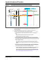
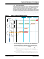
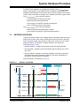
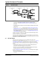
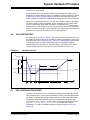
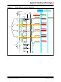
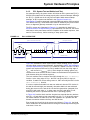
® SYSTEM HARDWARE PRINCIPLES Chapter 4. ECU Requirements For robustness, INIC must be able to power up properly, lock to the network, and revert to sleep power state if the EHC never attaches. Therefore, the INIC PWROFF pin must go to the power management circuitry to manage the transition between the sleep power state and active power state. As long as the EHC maintains its connection to INIC through regular communication, keeping INIC in the attached state or the network is in state NetOn, INIC will keep the PWROFF pin low keeping the device powered up. When it is time to go to sleep power state, the EHC can control the PWROFF pin via the INIC.PMIState.Set(PWROFF_HI) command. The EHC can further limit reverting to sleep power state by using its own GPIO pin to the power management circuitry. If the EHC uses a GPIO in lieu of, or in addition to the INIC PWROFF pin, the EHC’s GPIO reset default must not impede reverting to sleep power state (must be high impedance). INIC.RemoteAccess() must be enabled to allow remote ECU testing. An example test is for a remote network tool to send the device an INIC.Reset() command either resetting the INIC, the EHC or both. The expected result is the EHC recovers properly from any local reset event. For a detailed explanation of the hardware concepts for a MOST network device as well as hardware implementation examples, see the MOST INIC Hardware Concepts Specification [4]. 4.1 RESETS At initial power up or when exiting from sleep power state, INIC must be powered and properly reset independently of EHC. This scenario allows the network to become operational regardless of the state of the EHC. The reset generator must be designed to assert reset over the proper voltage range and over the entire temperature range to insure that in a brown-out condition INIC gets a proper reset. The lower limit of reset is specified in the OS81092 INIC Hardware Data Sheet [7], section ‘Guaranteed Operating Conditions’. The upper limit of reset assertion shall be just below the absolute minimum of the network switched power supply voltage (NwSwP) as described in the MOST INIC Hardware Concepts Specification [4]. Therefore, a trade-off exists between the accuracy of the switched network power supply connected to INIC and the accuracy required in the reset generator. For example, if the NwSwP power supply is ±2%, then the reset generator must assert between 0.98xNwSwP and 0.9xNwSwP. However, if the NwSwP power supply is ±5%, then the reset generator must assert between the tighter range of 0.95xNwSwP and 0.9xNwSwP. As illustrated in Figure 4-1, the INIC RSOUT pin shall be attached to the EHC reset line. The EHC shall have a GPIO line connected to the INIC RST (reset) pin. 2013 Microchip Technology Inc. DS20005241A-page 21