1
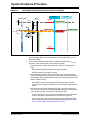
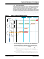
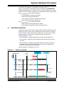
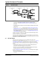
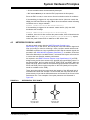
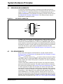
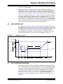
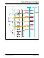
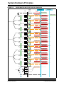
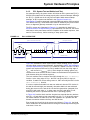
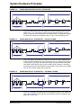
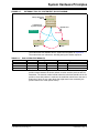
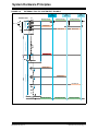
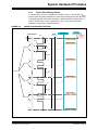
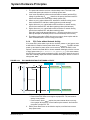
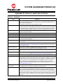
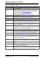
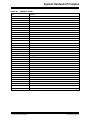
System Hardware Principles FIGURE A-7: EXTERNAL TOOL ECL SYSTEM TEST BLOCK DIAGRAM %DWWHU\&RQWLQXRXV3RZHU %DW&RQ3 +8 6OHHS3RZHU6WDWH 1HWZRUN0DVWHU 7LPLQJ0DVWHU /RFDO:DNHXS(YHQWV HJ&$1'RRU2SHQHG 3RZHU0DVWHU 5LQJ%UHDNRU6KRUW ([WHUQDO7HVW7RRO 02671HWZRUN (&/ $PS $X[,Q 6OHHS3RZHU6WDWH 6OHHS3RZHU6WDWH %DW&RQ3 %DW&RQ3 The external test tool initiates an ECL system test as shown in Figure A-8. The external test tool collects the following during the Results sequence. TABLE A-1: ECU ECU SYSTEM TEST RESULTS En Results Node Class Head Unit On Results 1 0 HU alive 1 Did not detect stable lock AuxIn 2 0 AuxIn alive 1 Did not detect stable lock Amplifier 3 0 Amp alive 1 Did not detect stable lock The first device in the ring, the AuxIn, did not detect stable lock indicating a problem exists between the AuxIn network receiver and the previous device’s transmitter. The test tool results indicate where the technician should look for the problem. Once that problem is resolved, the technician should rerun the test to determine if there are any other faults that might have been masked by the problem before the AuxIn (double faults). 2013 Microchip Technology Inc. DS20005241A-page 33