1
Introduction
This manual explains the items required for installing and connecting the C70.
Read this manual thoroughly and understand the product's functions and performance before starting to
use.
This manual is written on the assumption that all option functions are added, but the actually delivered
device may not have all functions.
The unit names, cable names and various specifications are subject to change without notice. Please
confirm these before placing an order.
For safe use, fully understand "Precautions for Safety" on the next page first.
Details described in this manual:
CAUTION
For items described as "Restrictions" or "Usable State" in this manual, the instruction manual issued by
the machine tool builder takes precedence over this manual.
Items that are not described in this manual must be interpreted as "not possible".
This manual is written on the assumption that all option functions are added. Confirm the specifications
issued by the machine tool builder before use.
Refer to the Instruction Manual issued by each machine tool builder for details on each machine tool.
Some screens and functions may differ depending on each NC system (or version), and some functions
may not be possible. Please confirm the specifications before use.
Refer to the following documents.
GOT2000 Series User's Manual (Hardware) ................................................... SH-081194ENG
GT16 User's Manual (Hardware) ..................................................................... SH-080928ENG
GT15 User's Manual ........................................................................................ SH-080528ENG
QCPU User's Manual (Hardware Design, Maintenance and Inspection) ........ SH-080483ENG
MDS-D2/DH2 Series Specifications Manual .................................................... IB-1501124(ENG)
MDS-D2/DH2 Series Instruction Manual ......................................................... IB-1501127(ENG)
MDS-DM2 Series Specifications Manual ......................................................... IB-1501136(ENG)
MDS-DM2 Series Instruction Manual ............................................................... IB-1501139(ENG)
MDS-DJ Series Specifications Manual ............................................................. IB-1501130(ENG)
MDS-DJ Series Instruction Manual .................................................................. IB-1501133(ENG)
MDS-D/DH Series Instruction Manual .............................................................. IB-1500025(ENG)
MDS-D-SVJ3/SPJ3 Series Instruction Manual ................................................ IB-1500193(ENG)
MDS-DM Series Instruction Manual ................................................................. IB-1500893(ENG)
Safety Handbook (Original Instructions) .......................................................... IB-1501026(ENG)
Precautions for Safety
Always read this manual and enclosed documents before installation, operation, maintenance and inspection to
ensure correct usage. Thoroughly understand the basics, safety information and precautions of the devices before
using.
This manual classifies the safety precautions into "DANGER", "WARNING" and "CAUTION".
DANGER
WARNING
CAUTION
When the user could be subject to imminent fatalities or serious injuries if handling is
mistaken.
When the user could be subject to fatalities or serious injuries if handling is mistaken.
When the user could be subject to injuries or the property could be damaged if handling is
mistaken.
Note that the items under "
CAUTION" could lead to serious consequences as well depending on the situation.
All the items are important and must always be observed.
The following sings indicate prohibition and compulsory.
This sign indicates prohibited behavior (must not do).
For example,
indicates "Keep fire away".
This sign indicated a thing that is pompously (must do).
For example,
indicates "it must be grounded".
The meaning of each pictorial sing is as follows.
CAUTION
CAUTION
rotated object
CAUTION
HOT
Danger
Electric shock risk
Danger
explosive
Prohibited
Disassembly is
prohibited
KEEP FIRE AWAY
General instruction
Earth ground
For Safe Use
This product is not designed or manufactured on the assumption that the product will be used for the
equipment or systems that are to be subject to any fatal consequences. Please inquire our customer
service department about any particular usage other than the normal usage as a machine tool.
1. Items related to prevention of electric shocks.
WARNING
Do not open/close the front cover while the power is ON or during operation. The high voltage terminals and
charged sections will be exposed, and this could result in electric shocks.
Do not remove the front cover even when the power is OFF, except for the wiring works or periodic inspections.
The inside of the controller and servo drive unit are charged, and this could result in electric shocks.
Always wait at least 15 minutes after turning the power OFF. Then, check the voltage with a tester, etc., before
wiring works, inspections or connecting with peripheral devices. Failure to observe this could result in electric
shocks.
Earth ground the controller, servo drive unit and servomotor according to the local laws. (In Japan, ground the
200V Series input products with Class C or higher protective grounding and the 400V Series input with Class D
or higher protective grounding.)
All wiring works, maintenance and inspections must be carried out by a qualified technician. Failure to observe
this could result in electric shocks. Contact your nearby Service Center or Service Station for replacing parts
and servicing.
Wire the controller, servo drive unit and servomotor after installation. Failure to observe this could result in
electric shocks.
Do not operate the switches with wet hands. Failure to observe this could result in electric shocks.
Do not damage, apply excessive stress, place heavy things on or sandwich the cables. Failure to observe this
could result in electric shocks.
Insulate the power lead using a fixed terminal block. Failure to observe this could result in electric shocks.
Completely turn off the all lines of the power supply externally before wiring. Not completely turning off all power
could result in electric shock or damage to the product.
When turning on the power supply or operating the module after wiring, be sure that the module's terminal
covers are correctly attached. Not attaching the terminal cover could result in electric shock.
2. Items related to prevention of fire
CAUTION
Install the controller, servo drive unit, servomotor and regenerative resistor on non-combustible material.
Installation directly on or near combustible materials could result in fires.
If any malfunction in the unit is observed, shut off the power at the unit’s input power side. Continuous flow of
large current could result in fires.
Install an appropriate NFB (circuit breaker) and MC (contactor) on the power input section of the servo drive unit
and configure the sequence that shuts the power off upon drive unit’s emergency stop or alarm.
When a breaker is shared for multiple power supply units, the breaker may not function upon short-circuit failure
in a small capacity unit. Do not share a breaker for multiple units as this is dangerous.
Incorrect wiring and connections could cause the devices to damage or burn.
3. Items related to prevention of bodily injury or property damage
DANGER
When transporting or installing a built-in IPM spindle or linear servomotor, be careful so that your hand or
property will not be trapped in the servomotors or other metal objects. Also keep the devices with low magnetic
tolerance away from the product.
CAUTION
Do not apply voltages to other than those indicated in the connection manual for the controller or specifications
manual for the servo drive unit. Failure to observe this could cause the devices to rupture or damage, etc.
Incorrect terminal connections could cause the devices to rupture or damage, etc.
Incorrect polarity (+ -) could cause the devices to rupture or damage, etc.
Persons wearing medical devices, such as pacemakers, must stay away from this unit. The electromagnetic
waves could adversely affect the medical devices.
Fins on the rear of the unit, regenerative resistor and servomotor, etc., will be hot during operation and for a
while after the power has been turned OFF. Do not touch or place the parts and cables, etc. close to these
sections. Failure to observe this could result in burns.
Do not enter the machine’s movable range during automatic operation. Keep your hands, feet or face away from
the spindle during rotation.
4. General Precautions
Always follow the precautions below. Incorrect handling could result in faults, injuries or electric shocks, etc.
(1) Transportation and installation
CAUTION
Correctly transport the products according to the weights.
Use servomotor’s suspension bolts to transport the servomotor itself. Do not use it to transport the servomotor
after installation onto the machine.
Do not stack the products exceeding the indicated limit.
Do not hold the cables, shaft or detector when transporting the servomotor.
Do not transport the controller or servo drive unit by suspending or holding the connected wires or cables.
Do not hold the front cover when transporting the servo drive unit, or the front cover could come off, causing the
unit to drop.
Install on a non-combustible place where the unit’s or motor’s weight can be withstood according to the
instruction manual.
The servomotor does not have a complete water-proof (oil-proof) structure. Do not allow oil or water to contact
or enter the motor. Prevent the oil-soaked cutting chips from being accumulated on the motor.
When installing the motor facing upwards, take measures on the machine side so that gear oil, etc., will not
enter the motor shaft.
Do not remove the detector from the servomotor. (The detector installation screw is treated with sealing.)
Do not allow foreign matters, especially, conductive foreign matters such as screws or metal chips, or
combustible foreign matters such as oil, to enter the controller, servo drive unit or servomotor. Failure to
observe this could result in rupture or damage.
Do not get on the product or place heavy objects on it.
Provide appropriate distance between the controller/servo drive unit and inner surface of the control panel/other
devices.
Do not install or operate the controller, servo drive unit or servomotor that is damaged or has missing parts.
Take care not to cut hands, etc. with the heat radiating fins or metal edges.
Do not block the intake/outtake ports of the servomotor with the cooling fan.
CAUTION
Install the controller’s display unit and operation board unit on the spot where cutting oil will not reach.
The controller, servo drive unit and servomotor are precision devices, so do not drop or apply thumping vibration
and strong impacts on them.
Hard disk unit is a precision device, so do not drop or apply strong impacts on it.
Store and use the units according to the environment conditions indicated in each specifications manual.
When disinfectants or insecticides must be used to treat wood packaging materials, always use methods other
than fumigation (for example, apply heat treatment at the minimum wood core temperature of 56 °C for a
minimum duration of 30 minutes (ISPM No. 15 (2009))).
If products such as units are directly fumigated or packed with fumigated wooden materials, halogen
substances (including fluorine, chlorine, bromine and iodine) contained in fumes may contribute to the erosion
of the capacitors.
When exporting the products, make sure to comply with the laws and regulations of each country.
Do not use the products in conjunction with any components that contain halogenated flame retardants
(bromine, etc). Failure to observe this may cause the erosion of the capacitors.
Securely fix the motor to the machine. The motor could come off during operation if insecurely fixed.
Always install the servomotor with reduction gear in the designated direction. Failure to observe this could result
in oil leaks.
Always install a cover, etc., over the shaft so that the rotary section of the spindle motor cannot be touched
during motor rotation.
When using a coupling connection to the servomotor shaft end, do not apply impacts by hammering, etc. The
detector could be damaged.
Use a flexible coupling when connecting with a ball screw, etc., and keep the shaft core deviation smaller than
the tolerable radial load of the shaft.
Do not use a rigid coupling as an excessive bending load will be applied on the shaft and could cause the shaft
to break.
Do not apply a load exceeding the tolerable level onto the motor shaft. The shaft or bearing could be damaged.
Before using this product after a long period of storage, please contact the Mitsubishi Service Station or Service
Center.
Following the UN recommendations, battery units and batteries should be transported based on the
international regulations such as those determined by International Civil Aviation Organization (ICAO),
International Air Transport Association (IATA), International Maritime Organization (IMO) and U.S. Department
of Transportation (DOT).
Due to ventilation problems, do not install the base units vertically or horizontally when C70 is mounted on a
board, etc.
Install the basic base on a flat surface. Unevenness or warping of the surface can apply undue force to printed
circuit boards and lead to operation failures.
Avoid installing the base units close to a vibration source, such as a large electromagnetic contactor or no-fuse
breaker. Install them on a separate panel or at a safe distance.
To limit the effects of reflected noise and heat, leave 100mm(3.94inch) or more clearance to instruments fitted in
front of CNC CPU (on the rear of the door).
Similarly, leave 50mm(1.97inch) or more clearance between instruments and the left and right sides of the basic
base.
(2) Items related to wiring
CAUTION
Correctly wire this product. Failure to observe this could result in servomotor runaway, etc.
Do not install a phase advancing capacitor, surge absorber or radio noise filter on the output side of the servo
drive unit.
Correctly connect the output side (terminal U, V, W). The servomotor will not run properly if incorrectly
connected.
Always install an AC reactor per each power supply unit.
Always install an appropriate breaker per each power supply unit. A breaker cannot be shared for multiple power
supply units.
Do not directly connect a commercial power supply to the servomotor. Failure to observe this could result in
faults.
When using an inductive load such as relays, always connect a diode in parallel to the load as a noise
countermeasure.
When using a capacitive load such as a lamp, always connect a protective resistor in series to the load to
suppress rush currents.
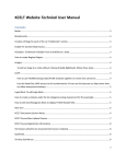
Do not mistake the direction of the surge absorption diode to be installed on the DC relay for the control output
signal. If mistaken, the signal will not be output due to fault in the drive unit, and consequently the protective
circuit, such as emergency stop, could be disabled.
Drive unit
Drive unit
COM
(24VDC)
Control
output
signal
COM
(24VDC)
RA
Control
output
signal
RA
Do not connect or disconnect the connection cables between each unit while the power is ON.
Do not connect or disconnect the PCBs while the power is ON.
Do not pull the cables when connecting/disconnecting it.
Securely tighten the cable connector fixing screw or fixing mechanism. Insufficient fixing could result in
dislocation during operation.
Always treat the shield cables indicated in the Connection Manual with grounding measures such as cable
clamps.
Separate the signal wire from the drive line or power line when wiring.
Carry out wiring so that there is no possibility of short circuit between wires, nor of dangerous state.
CAUTION
Use wires and cables whose wire diameter, heat resistance level and bending capacity are compatible with the
system.
Ground the device according to the requirements of the country where the device is to be used.
Wire the heat radiating fins and wires so that they do not contact.
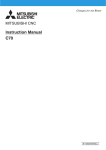
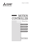
When using the RS-232C device as a peripheral device, caution must be paid for connector connection/
disconnection.
Always use a double-OFF type AC power supply switch on the device side, and connect/disconnect the
connector with the AC power supply on the device side OFF.
Device
NC unit
Switch
AC socket
RS-232C
Be sure to ground the earth terminal FG and LG. Not doing so could result in electric shock or operation failure.
(Ground resistance: 100Ω or less)
When wiring in the unit, be sure that it is done correctly by checking the product's rated voltage and the terminal
layout. Connecting a power supply that is different from the rating or incorrectly wiring the product could result in
fire or damage.
External connections shall be crimped or pressure welded with the specified tools, or correctly soldered.
Imperfect connections could result in short circuit, fire, or operation failure.
Tighten the terminal screws within the specified torque range. If the terminal screws are loose, it could result in
short circuit, fire, or operation failure. Tightening the terminal screws too far may cause damages to the screws
and/or the module, resulting in drop, short circuit, or operation failure.
Be sure there are no foreign matters such as sawdust or wiring debris inside the module. Such debris could
cause fire, damage, or operation failure.
The module has an ingress prevention label on its top to prevent foreign matter, such as wiring debris, from
entering the module during wiring.
Do not remove this label during wiring.
Before starting system operation, be sure to remove this label because of heat dissipation.
When connecting to a personal computer and a unit with the USB interface, an electric shock or a
unit failure may occur.
Operate these correctly according to the manual of a unit and a personal computer.
Observe the following cautions when a personal computer in an AC power supply is used.
(1) For a personal computer that uses a 3-pin power plug or power plug with a ground lead type, make sure to
use a plug socket including a ground input electrode or ground the earth lead, respectively.
(2) For a personal computer that uses a 2-pin power plug without ground lead, make sure to connect the unit
to the personal computer according to the following procedures.
And, it is recommended to supply the same power supply line to a personal computer and the unit.
(a) Pull out the power plug of the personal computer from the AC outlet.
(b) Confirm that the power plug of the personal computer has been pulled out from the AC outlet, and
connect USB cables.
(c) Insert the power plug of the personal computer into the AC outlet.
(3) Adjustments
CAUTION
Check and adjust programs and each parameter before starting operation. Unpredictable operations could
occur depending on the machine.
Do not make drastic adjustments or changes as the operation could become unstable.
(4) Usage
CAUTION
Use C70 in an environment that meets the general specifications contained in this manual. Using C70 in an
environment outside the range of the general specifications could result in electric shock, fire, operation failure,
and damage to or deterioration of the product.
When mounting the module, be sure to insert the module fixing hook on the module's bottom into the module
fixing hole on the base unit. Incorrect mounting could cause an operation failure or a damage/drop of the unit.
Hold down the module loading lever at the module bottom and securely insert the fixing hook into the fixing hole
in the base unit. Install the module with the module fixing hole as a supporting point. Incorrect loading of the
module can cause an operation failure, failure or drop.
Be sure to fix all the modules with screws to prevent them from dropping.
The fixing screws (M3 x 12) are to be prepared by user. For CNC CPU module, use the attached fixing screws
(M3 x 13).
Tighten the screw in the specified torque range. Under tightening may cause a drop, short circuit or operation
failure. Over tightening may cause a drop, short circuit or operation failure due to damage to the screw or
module.
Be sure to install the extension cable to connectors of the basic base unit correctly. After installation, check
them for looseness. Poor connections could cause an input or output failure.
Completely turn off all lines of external power supply used in the system before loading or unloading the
module. Not doing so could result in electric shock or damage to the product.
Do not mount/dismount the modules or base over 50 times. Mounting/dismounting over 50 times may cause an
operation failure.
Do not directly touch the module's conductive parts or electronic parts. Touching these parts could cause an
operation failure or give damage to the module.
Do not touch the radiating fin of the CNC CPU module while an electric current is supplied or in a short while
after the power OFF. Touching the fin may cause burns. Take care when removing the unit.
When removing the unit, always remove the fixing screws and then take the fixing hook out from the fixing hole.
Incorrect removal will damage the module fixing hook.
CAUTION
Install an external emergency stop circuit so that the power will turn OFF followed by the immediate operation
stop. A contactor, etc., is required in addition to the shutoff function mounted in the controller.
Turn OFF the power immediately if any smoke, abnormal noise or odor is generated from the controller, servo
drive unit or servomotor.
Only a qualified technician may disassemble or repair this product.
Do not alter.
Use a noise filter, etc. to reduce the effect of electromagnetic disturbances. Electromagnetic disturbances could
adversely affect the electronic devices used near the servo drive unit.
Use the servo drive unit, servomotor and each regenerative resistor with the designated combination. Failure to
observe this could result in fires or faults.
The combination of the servomotor and servo drive unit that can be used is determined. Be sure to check the
models of servomotor and servo drive unit before test operation.
The brakes (electromagnetic brakes) mounted in the servomotor are used for the purpose of holding, and must
not be used for normal braking. Also, do not run the motor with the motor brake applied. Motor brake is used for
the purpose of holding.
For the system running via a timing belt, install a brake on the machine side so that safety can be ensured.
Be sure to confirm SERVO OFF (or READY OFF) when applying the magnetic brake. Also, be sure to confirm
SERVO ON prior to releasing the brake.
When using the DC OFF type electromagnetic brake, be sure to install a surge absorber on the brake terminal.
Do not connect or disconnect the cannon plug while the electromagnetic brake’s power is ON. The cannon plug
pins could be damaged by sparks.
After changing programs/parameters, or after maintenance/inspection, always carry out a test operation before
starting actual operation.
Use the power (input voltage, input frequency, tolerable instantaneous power failure time) that are complied
with the power specification conditions indicated in each Specifications manual.
When making detector cables, do not mistake connection. Failure to observe this could result in malfunction,
runaway or fire.
(5) Troubleshooting
CAUTION
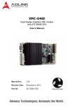
Use a servomotor with electromagnetic brakes or
establish an external brake mechanism for the
purpose of holding; this serves as countermeasures
Shut off with motor
brake control output
Shut off with CNC brake
control PLC output
for possible hazardous situation caused by power
failure or product fault.
Use a double circuit structure for the
electromagnetic brake’s operation circuit so that the
brakes will activate even when the external
Motor
Electromagnetic
brake
MBR
EMG
24VDC
emergency stop signal is issued.
The machine could suddenly restart when the power is restored after an instantaneous power failure, so stay
away from the machine. (Design the machine so that the operator safety can be ensured even if the machine
restarts.)
To secure the absolute position, do not shut off the servo drive unit’s control power supply when its battery
voltage becomes low (warning 9F)
If the battery voltage drop warning alarm occurs, make sure to back up the machining programs, tool data and
parameters, etc. with the input/output device before replacing the battery.
Depending on the level of voltage drop, there is the possibility of memory loss. Reload all the data backed up
before the alarm occurrence.
(6) Maintenance, inspection and part replacement
CAUTION
Periodically back up the programs, tool data and parameters to avoid potential data loss. Also, back up those
data before maintenance and inspections.
When replacing the battery on the controller side, the machining programs, tool data and parameters, etc.,
should be backed up with the input/output device beforehand.
In case the memory is damaged in replacing the batteries, reload all the data backed up before the alarm
occurrence.
The electrolytic capacitor’s capacity will drop due to deterioration. To prevent secondary damage due to
capacitor’s faults, Mitsubishi recommends the electrolytic capacitor to be replaced approx. every five years
even when used in a normal environment. Contact the Service Center or Service Station for replacements.
Do not perform a megger test (insulation resistance measurement) during inspection.
Do not replace parts or devices while the power is ON.
Do not short-circuit, charge, overheat, incinerate or disassemble the battery.
There may be a unit filled with substitute Freon in the heat radiating fins of the 37kW or smaller unit. Be careful
not to break the heat radiating fins during maintenance or replacement.
(7) Disposal
CAUTION
Take the batteries and backlights for LCD off from the controller, servo drive unit and servomotor, and dispose
of them as general industrial wastes.
Do not alter or disassemble controller, servo drive unit, or servomotor.
Dispose of the spent batteries and the backlights for LCD according to the local laws.
(8) General precautions
To explain the details, drawings given in this instruction manual, etc., may show the unit with the cover or safety partition
removed. When operating the product, always place the cover or partitions back to their original position, and operate as
indicated in the instruction manual, etc.
Treatment of waste
The following two laws will apply when disposing of this product. Considerations must be made to each law.
The following laws are in effect in Japan. Thus, when using this product overseas, the local laws will have a
priority. If necessary, indicate or notify these laws to the final user of the product.
(1) Requirements for "Law for Promotion of Effective Utilization of Resources"
(a) Recycle as much of this product as possible when finished with use.
(b) When recycling, often parts are sorted into steel scraps and electric parts, etc., and sold to scrap
contractors. Mitsubishi recommends sorting the product and selling the members to appropriate
contractors.
(2) Requirements for "Law for Treatment of Waste and Cleaning"
(a) Mitsubishi recommends recycling and selling the product when no longer needed according to item
(1) above. The user should make an effort to reduce waste in this manner.
(b) When disposing a product that cannot be resold, it shall be treated as a waste product.
(c) The treatment of industrial waste must be commissioned to a licensed industrial waste treatment
contractor, and appropriate measures, including a manifest control, must be taken.
(d) Batteries correspond to "primary batteries", and must be disposed of according to local disposal
laws.
Disposal
(Note)
This symbol mark is for EU countries only.
This symbol mark is according to the directive 2006/66/EC Article 20 Information for endusers and Annex II.
Your MITSUBISHI ELECTRIC product is designed and manufactured with high quality materials and
components which can be recycled and/or reused.
This symbol means that batteries and accumulators, at their end-of-life, should be disposed of
separately from your household waste.
If a chemical symbol is printed beneath the symbol shown above, this chemical symbol means that the
battery or accumulator contains a heavy metal at a certain concentration. This will be indicated as
follows:
Hg: mercury (0,0005%), Cd: cadmium (0,002%), Pb: lead (0,004%)
In the European Union there are separate collection systems for used batteries and accumulators.
Please, dispose of batteries and accumulators correctly at your local community waste collection/
recycling centre.
Please, help us to conserve the environment we live in!
Trademarks
MELDAS, MELSEC, EZSocket, EZMotion, iQ Platform, MELSOFT, GOT, CC-Link, CC-Link/LT and CC-Link
IE are either trademarks or registered trademarks of Mitsubishi Electric Corporation in Japan and/or other
countries.
Ethernet is a registered trademark of Xerox Corporation in the United States and/or other countries.
Microsoft® and Windows® are either trademarks or registered trademarks of Microsoft Corporation in the
United States and/or other countries.
CompactFlash and CF are either trademarks or registered trademarks of SanDisk Corporation in the United
States and/or other countries.
Other company and product names that appear in this manual are trademarks or registered trademarks of the
respective companies.
本製品の取扱いについて
( 日本語 /Japanese)
本製品は工業用 ( クラス A) 電磁環境適合機器です。販売者あるいは使用者はこの点に注意し、住商業環境以外で
の使用をお願いいたします。
Handling of our product
(English)
This is a class A product. In a domestic environment this product may cause radio interference in which case the
user may be required to take adequate measures.
본 제품의 취급에 대해서
( 한국어 /Korean)
이 기기는 업무용 (A 급 ) 전자파적합기기로서 판매자 또는 사용자는 이 점을 주의하시기 바라며 가정외의 지역에
서 사용하는 것을 목적으로 합니다 .
CONTENTS
1 System Configuration.................................................................................................................................. 1
1.1 System Basic Configuration Drawing..................................................................................................... 2
1.2 General Connection Diagram ................................................................................................................ 3
1.3 Component Modules.............................................................................................................................. 4
1.3.1 CNC Control Unit ........................................................................................................................... 4
1.3.2 GOT ............................................................................................................................................. 23
1.3.2.1 GT27.................................................................................................................................... 23
1.3.2.2 GT16.................................................................................................................................... 25
1.3.2.3 GT15.................................................................................................................................... 27
1.3.2.4 Option .................................................................................................................................. 28
1.3.3 Peripheral Device......................................................................................................................... 29
1.3.4 Dual Signal Module...................................................................................................................... 29
2 General Specifications .............................................................................................................................. 31
2.1 Installation Environment Conditions..................................................................................................... 32
2.2 Base Unit ............................................................................................................................................. 33
2.3 Power Supply....................................................................................................................................... 34
2.4 PLC CPU ............................................................................................................................................. 39
2.5 CNC CPU Module................................................................................................................................ 46
2.6 Battery Box for CNC CPU (Q173NCCPU) ........................................................................................... 50
2.7 Dual Signal Module.............................................................................................................................. 51
2.8 Signal Splitter....................................................................................................................................... 55
2.9 Manual Pulse Generator ...................................................................................................................... 57
2.10 Terminal block for Dual Signal Module (Recommended) .................................................................. 59
2.11 I/O Extension Connector Unit ............................................................................................................ 60
3 Installation .................................................................................................................................................. 65
3.1 Module Installation ............................................................................................................................... 66
3.1.1 Precautions for Handling.............................................................................................................. 66
3.1.2 Precautions for Installation of Basic Base Unit ............................................................................ 69
3.1.3 Module Installation and Removal................................................................................................. 71
3.2 Precautions for Mounting the Battery Holder Unit................................................................................ 73
3.3 Calculating Heat Generation by C70 ................................................................................................... 74
4 Wiring and Connecting.............................................................................................................................. 77
4.1 Precautions .......................................................................................................................................... 78
4.1.1 Power supply wiring ..................................................................................................................... 78
4.1.2 Wiring of I/O equipment ............................................................................................................... 79
4.1.3 Grounding .................................................................................................................................... 79
4.2 Wiring to the Power Supply Module..................................................................................................... 80
4.3 Connecting the Emergency Stop Signal .............................................................................................. 81
4.4 Connecting the GOT ............................................................................................................................ 82
4.5 Connecting the Servo Drive Unit.......................................................................................................... 83
4.5.1 Precautions for handling the optical fiber cable ........................................................................... 83
4.6 Connecting the Dual Signal Module..................................................................................................... 85
4.7 Connecting the Signal Splitter.............................................................................................................. 86
4.8 Connecting the Skip Signal (Sensor) ................................................................................................... 87
4.9 Connecting the Manual Pulse Generator............................................................................................. 88
4.10 Connecting the I/O Extension Connector Unit ................................................................................... 91
Appendix 1 EMC Installation Guidelines .................................................................................................... 93
Appendix 1.1 Introduction .......................................................................................................................... 94
Appendix 1.2 EMC Directives .................................................................................................................... 95
Appendix 1.3 EMC Measures .................................................................................................................... 96
Appendix 1.4 Panel Structure .................................................................................................................... 96
Appendix 1.4.1 Measures for Control Panel Body ................................................................................ 96
Appendix 1.4.2 Measures for Door ....................................................................................................... 97
Appendix 1.4.3 Measures for Power Supply......................................................................................... 97
Appendix 1.5 Measures for Wiring in Panel ............................................................................................... 98
Appendix 1.5.1 Precautions for Wiring in Panel.................................................................................... 98
Appendix 1.5.2 Shield Treatment of Cables ......................................................................................... 98
Appendix 1.6 EMC Countermeasure Parts ................................................................................................ 99
Appendix 1.6.1 Shield Clamp Fitting..................................................................................................... 99
Appendix 1.6.2 Ferrite Core................................................................................................................ 100
Appendix 1.6.3 Surge Absorber.......................................................................................................... 102
Appendix 1.6.4 Selection of Stabilized Power Supply ........................................................................ 104
Appendix 2 Cable ........................................................................................................................................ 105
Appendix 2.1 Cable Wire and Assembly.................................................................................................. 107
Appendix 2.2 CNP2E-1 Cable.................................................................................................................. 109
Appendix 2.3 CNV22J-K1P / CNV22J-K2P Cable ................................................................................... 110
Appendix 2.4 CNV2E-8P/CNV2E-9P Cable............................................................................................. 111
Appendix 2.5 CNV2E-D Cable ................................................................................................................. 112
Appendix 2.6 CNV2E-HP Cable............................................................................................................... 113
Appendix 2.7 CNV2E-K1P / CNV2E-K2P Cable...................................................................................... 114
Appendix 2.8 DG21 Cable ....................................................................................................................... 115
Appendix 2.9 DG22 Cable ....................................................................................................................... 115
Appendix 2.10 DG23 Cable ..................................................................................................................... 116
Appendix 2.11 DG24 Cable ..................................................................................................................... 116
Appendix 2.12 F020/F021/F022 Cable .................................................................................................... 117
Appendix 2.13 G020/G021/G022 Cable .................................................................................................. 118
Appendix 2.14 G302 Cable ...................................................................................................................... 119
Appendix 2.15 G303 Cable ...................................................................................................................... 119
Appendix 2.16 G380 Cable ...................................................................................................................... 120
Appendix 2.17 G395 Cable ...................................................................................................................... 121
Appendix 2.18 G396 Cable ...................................................................................................................... 122
Appendix 2.19 H010 Cable ...................................................................................................................... 123
Appendix 2.20 H100 Cable ...................................................................................................................... 124
Appendix 2.21 H200 Cable ...................................................................................................................... 124
Appendix 2.22 H300 Cable ...................................................................................................................... 125
Appendix 2.23 H310 Cable ...................................................................................................................... 126
Appendix 2.24 H400 Cable ...................................................................................................................... 126
Appendix 2.25 H500 Cable ...................................................................................................................... 127
Appendix 2.26 H810 Cable ...................................................................................................................... 128
Appendix 2.27 MR-BKS1CBL-A1-H / MR-BKS1CBL-A2-H Cable ........................................................... 129
Appendix 2.28 MR-PWS1CBL-A1-H / MR-PWS1CBL-A2-H Cable ......................................................... 129
Appendix 2.29 SH21 Cable...................................................................................................................... 130
Appendix 3 Restrictions for Lithium Batteries ......................................................................................... 131
Appendix 3.1 Restriction for Packing ....................................................................................................... 132
Appendix 3.1.1 Target Products ......................................................................................................... 133
Appendix 3.1.2 Handling by User ....................................................................................................... 134
Appendix 3.1.3 Reference .................................................................................................................. 135
Appendix 3.2 Products information data sheet (ER battery) .................................................................... 136
Appendix 3.3 Issuing Domestic Law of the United States for Primary Lithium Battery Transportation.... 138
Appendix 3.3.1 Outline of Regulation ................................................................................................. 138
Appendix 3.3.2 Target Products ......................................................................................................... 138
Appendix 3.3.3 Handling by User ....................................................................................................... 138
Appendix 3.3.4 Reference .................................................................................................................. 138
Appendix 3.4 Restriction related to EU Battery Directive......................................................................... 139
Appendix 3.4.1 Important Notes ......................................................................................................... 139
Appendix 3.4.2 Information for end-user............................................................................................. 139
Appendix 4 Precautions for Compliance to UL/c-UL Standards ............................................................ 141
1
System Configuration
1
MITSUBISHI CNC
1. System Configuration
1.1 System Basic Configuration Drawing
HMI GOT
GT Works3
Memory card
or USB
CNC UNIT
EMG
GX Works2
GX Developer
CPU
Q 170D BAT
C
BATTER
Y
MANUAL PLG
M IT S U B IS H I
LIT H IU M
B A TTE RY
NC Configurator2
NC Analyzer
Battery
EXT. UNIT
QXxxxx
QXxxxx
QXxxxx
CNC Drive System
2
SKIP
C70 Connection Manual
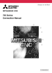
1.2 General Connection Diagram
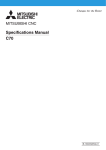
1.2 General Connection Diagram
Display module
GOT2000 Series
GOT1000 Se
Series
Specifications including unit names , cable
names, and maximum lengths of cables are
subject to change without notice . Always
confirm these details before placing an order.
H200 cable (panel internal wiring)
EMG
H100 Cable G302 cable (panel external wiring)
(Max:30m)
(Max:20m)
24VDC
(Note) Ethernet Module
GT15-J71E1-100 is
required for GT15
FG
24VDC or
100 240VAC
CPU Module
/Network Module
H500 Cable
(Max:0.5m)
H500
Cable
I/O
Module
#1
I/O
Module
#2
H500
Cable
Cable for ternimal block
F A-CBL
FMV-M
(Max:5m)
Battery
Q6BAT
Battery Unit
Q173NCBATC
MPG#1
I/O I/O I/O I/O
Mod- Mod- Mod- Module ule ule ule
#3 #4
#5 #6
RIO2
RIO1
PLCIO
NCIO
Dual
Signal
Module
RIO2
PLCIO
NCIO
RIO1
Dual
Signal
Module
Dual
Signal
Module
RIO2
CPU/
Network
Module
#2
PLCIO
NCIO
ACIN/DCIN
CPU/
Network
Module
#1
RIO1
Q312DB
EXT I/F
RIO
Source Power
AC/DC
CNCCPU
Module
Q173NCCPU
CN1
Basic
Base
EMG DISPLAY
I/F
BAT
MPG
Power
Unit
PLC
CPU
Module
MELSEC-Q I/O Module
/Intelligent Module
Dual Signal Module
Machine I/O
/Operation panel
CNC I/O
T erminal block type : F A-LTB40P
DCIN
H400 Cable
(Max:20m)
24VDC (Not used)
PLC I/O
T erminal block type : F A-LTB40P
DCIN
Manual Pulse Generator
UFO-01-2Z9 (5VDC)
Cable
G396 (max10m, for wiring
inside the panel)
G395 (max10m, for wiring
outside the panel)
G380 (max20m, for wiring
outside the panel)
24VDC (Not used)
SKIP signals . 4 points (24VDC)
H310 Cable
(Max:15m)
H010 Cable
(Max:5m)
Signal splitter
FCU7-HN387
SKIP
SW
TU I/F
MPG TERMINALDCIN
Drive Units
24VDC (Not used)
(12VDC) (Note1)
H300
Cable
(Max:20m)
Notes
MPG#2
SKIP
signals.
4 points
(24VDC)
Manual
Pulse
Generator
MPG#3
UFO-01-2Z9 (5VDC)
: Prepared by user
: Used with connector.
Cannot be used with cable H300 at the same time
(Note 1) HD60C (12VDC) requires another power source12VDC.
Cable
G020(5VDC,1ch,Max:15m)
G021(5VDC,2ch,Max:15m)
G022(5VDC,3ch,Max:15m)
F020(12VDC,1ch,Max:45m)
F021(12VDC,2ch,Max:45m)
F022(12VDC,3ch,Max:45m)
HD60C (12VDC) (Note1)
3
MITSUBISHI CNC
1. System Configuration
1.3 Component Modules
1.3.1 CNC Control Unit
(1) Basic base
Model name
Remarks
Q35DB
5 slots
Q38DB
8 slots
Q312DB
12 slots
Reference
QCPU User’s Manual
(Hardware Design,
Maintenance and Inspection)
(SH(NA)-080483ENG)
(2) Power supply
Model name
4
Remarks
Q61P
Input power supply : 100 to 240VAC
Output power supply : 5VDC
Output current:6A
Q63P
Input power supply: 24VDC
Output power supply: 5VDC
Output current: 6A
Q64PN
Input power supply : 100 to 240VAC
Output power supply : 5VDC
Output current : 8.5A
Q64P
Input power supply: 100 to 120VAC/
200 to 240VAC
Output power supply: 5VDC
Output current: 8.5A
(Note) Out of production
Reference
QCPU User’s Manual
(Hardware Design,
Maintenance and Inspection)
(SH(NA)-080483ENG)
C70 Connection Manual
1.3 Component Modules
(3) PLC CPU
Model name
Remarks
Reference
Q03UDCPU
Program capacity: 30k steps
Q04UDHCPU
Program capacity: 40k steps
Q06UDHCPU
Program capacity: 60k steps
Q13UDHCPU
Program capacity:130k steps
Q26UDHCPU
Program capacity:260k steps
Q03UDECPU
Ethernet built-in type, Program capacity: 30k steps
Q04UDEHCPU
Ethernet built-in type, Program capacity: 40k steps
Q06UDEHCPU
Ethernet built-in type, Program capacity: 60k steps
Q10UDEHCPU
Ethernet built-in type, Program capacity: 100k steps
Q13UDEHCPU
Ethernet built-in type, Program capacity: 130k steps
Q26UDEHCPU
Ethernet built-in type, Program capacity: 260k steps
Q03UDVCPU
High-speed type, Program capacity: 30k steps
(Note)
Q04UDVCPU
High-speed type, Program capacity: 40k steps
(Note)
Q06UDVCPU
High-speed type, Program capacity: 60k steps
(Note)
Q13UDVCPU
High-speed type, Program capacity: 130k steps
(Note)
Q26UDVCPU
High-speed type, Program capacity: 260k steps
(Note)
(Note)
QCPU User’s Manual
(Hardware Design,
Maintenance and Inspection)
(SH(NA)-080483ENG)
The High-Speed Universal model is compatible with the safety observation function, but not yet
certified under the European safety standards “EN ISO 13849-1 Cat3 PL d” or “EN62061/SIL CL2”
by TÜV.
(4) CNC CPU module
Model name
Remarks
Q173NCCPU-S01
CNC CPU module
Battery kit
One each of following accessories are provided:
Battery holder unit+Connection cable (0.5m) Q173NCBATC(Q170DBATC), Battery
Q6BAT
(5) Battery holder unit
Model name
Q173NCBATC
Remarks
Battery holder unit
5
MITSUBISHI CNC
1. System Configuration
(6) Input module
(a) AC
Model name
Remarks
QX10
16 points, 100 to 120VAC
8mA(100VAC, 60Hz)/7mA(100VAC, 50Hz)
Response time: 20ms
16 points/common, 18-point terminal block
QX28
8 points, 100 to 240VAC
17mA(200VAC, 60Hz)
/14mA(200VAC, 50Hz)/8mA(100VAC, 60Hz)/
7mA(100VAC, 50Hz)
Response time: 20ms
8 points/common, 18-point terminal block
Reference
I/O module Type Building
Block User’s Manual
(SH(NA)-080042)
(b) DC (positive common type)
Model name
6
Remarks
QX40
16 points, 24VDC, 4mA,
Response time: 1/5/10/20/70ms
16 points/common, Positive common type
18-point terminal block
QX40-S1
16 points, 24VDC, 6mA,
Response time: 0.1/0.2/0.4/0.6/1ms
16 points/common, Positive common type
18-point terminal block
QX41
32 points, 24VDC, 4mA,
Response time: 1/5/10/20/70ms
32 points/common, Positive common type
40-pin connector
QX41-S1
32 points, 24VDC, 4mA,
Response time: 0.1/0.2/0.4/0.6/1ms
32 points/common, Positive common type
40-pin connector
QX42
64 points, 24VDC, 4mA,
Response time: 1/5/10/20/70ms
32 points/common, Positive common type
40-pin connector
QX42-S1
64 points, 24VDC, 4mA,
Response time: 0.1/0.2/0.4/0.6/1ms
32 points/common, Positive common type
40-pin connector
Reference
I/O module Type Building
Block User’s Manual
(SH(NA)-080042)
C70 Connection Manual
1.3 Component Modules
(c) DC sensor
Model name
Remarks
QX70
16 points, 5/12VDC, 1.2mA(5VDC)/3.3mA(12VDC)
Response time: 1/5/10/20/70ms
16 points/common, Positive/negative common type
18-point terminal block
QX71
32 points, 5/12VDC, 1.2mA(5VDC)/3.3mA(12VDC)
Response time: 1/5/10/20/70ms
32 points/common, Positive/negative common type
40-pin connector
QX72
64 points, 5/12VDC, 1.2mA(5VDC)/3.3mA(12VDC)
Response time: 1/5/10/20/70ms
32 points/common, Positive/negative common type
40-pin connector
Reference
I/O module Type Building
Block User’s Manual
(SH(NA)-080042)
(d) DC (negative common type)
Model name
Remarks
QX80
16 points, 24VDC, 4mA
Response time: 1/5/10/20/70ms
16 points/common, Negative common type
18-point terminal block
QX81
32 points, 24VDC, 4mA
Response time: 1/5/10/20/70ms
32 points/common, Negative common type
37-pin D sub-connector
QX82
64 points, 24VDC, 4mA
Response time: 1/5/10/20/70ms
32 points/common, Negative common type
40-pin connector
QX82-S1
64 points, 24VDC 4mA
Response time: 0.2/0.3/0.5/0.7/1.3ms
32 points/common, Negative common type
40-pin connector
Reference
I/O module Type Building
Block User’s Manual
(SH(NA)-080042)
7
MITSUBISHI CNC
1. System Configuration
(7) Analog input module
(a) Voltage input module
Model name
Q68ADV
Remarks
8 channels,
Input: -10 to 10VDC
Output (resolution): 0 to 4000; -4000 to 4000;
0 to 12000; -12000 to 12000; 0 to 16000;
-16000 to 16000
Conversion speed: 80µs/channel
18-point terminal block
Reference
Analog-Digital Converter
Module User's Manual
(SH(NA)-080055)
(b) Current input module
Model name
Remarks
Reference
Q62AD-DGH
2 channels,
Input: 4 to 20mADC
Output (resolution): 0 to 32000; 0 to 64000
Conversion speed: 10ms/2channels
18-point terminal block, Channels are isolated,
Power supply for 2-wire transmitter
Channel Isolated High
Resolution Analog-Digital
Converter Module/Channel
Isolated High Resolution
Analog-Digital Converter
Module (With Signal
Conditioning Function) User’s
Manual
(SH(NA)-080277)
Q68ADI
8 channels,
Input: 0 to 20mADC
Output (resolution): 0 to 4000; -4000 to 4000;
0 to 12000; -12000 to 12000; 0 to 16000;
-16000 to 16000
Conversion speed: 80µs/channel
18-point terminal block
Analog-Digital Converter
Module User's Manual
(SH(NA)-080055)
(c) Voltage/current input module
Model name
Q64AD
Q64AD-GH
8
Remarks
Reference
4 channels,
Input: -10 to 10VDC, 0 to 20mADC
Output (resolution): 0 to 4000; -4000 to 4000;
0 to 12000; -12000 to 12000; 0 to 16000;
-16000 to 16000
Conversion speed: 80µs/channel
18-point terminal block
Analog-Digital Converter
Module User's Manual
(SH(NA)-080055)
4 channels,
Input: -10 to 10VDC, 0 to 20mADC
Output (resolution): 0 to 32000; -32000 to 32000;
0 to 64000; -64000 to 64000
Conversion speed: 10ms/4channels
18-point terminal block, Channels are isolated
Channel Isolated High
Resolution Analog-Digital
Converter Module/Channel
Isolated High Resolution
Analog-Digital Converter
Module (With Signal
Conditioning Function) User’s
Manual
(SH(NA)-080277)
C70 Connection Manual
1.3 Component Modules
(8) Output module
(a) Relay
Model name
Remarks
QY10
16 points, 24VDC/240VAC, 2A/point, 8A/common
Response time: 12ms 16 points/common
18-point terminal block
QY18A
8 points, 24VDC/240VAC, 2A/point
Response time: 12ms
18-point terminal block, All relays isolated
Reference
I/O module Type Building
Block User’s Manual
(SH(NA)-080042)
(b) Triac
Model name
Remarks
16 points, 100 to 240VAC, Minimum load voltage
Current: 24VAC, 100mA/100/240VAC, 25mA,
OFF-time leakage current: 1.5mA(120VAC)/
3mA(240VAC)
Response time: 1ms+0.5 cycle
16 points/common, 18-point terminal block
Surge killer provided
QY22
Reference
I/O module Type Building
Block User’s Manual
(SH(NA)-080042)
(c) Transistor (sink type)
Model name
Remarks
QY40P
16 points, 12 to 24VDC
OFF-time leakage current: 0.1mA
Response time: 1ms, 16 points/common, Sink type
18-point terminal block, Thermal protection
provided, Short circuit protection provided
Surge killer provided
QY41P
32 points, 12 to 24VDC
OFF-time leakage current: 0,1mA
Response time: 1ms, 32 points/common, Sink type
40-pin connector, Thermal protection provided
Short circuit protection provided
Surge killer provided
QY42P
64 points, 12 to 24VDC
OFF-time leakage current: 0.1mA
Response time: 1ms, 32 points/common, Sink type
40-pin connector, Thermal protection provided
Short circuit protection provided
Surge killer provided
QY50
16 points, 12 to 24VDC
OFF-time leakage current: 0.1mA
Response time: 1ms, 16 points/common, Sink type
18-point terminal block, Surge killer provided
Fuse provided
Reference
I/O module Type Building
Block User’s Manual
(SH(NA)-080042)
9
MITSUBISHI CNC
1. System Configuration
(d) Transistor (independent)
Model name
Remarks
8 points, 5 to 24VDC
OFF-time leakage current: 0.1mA
Response time: 10ms, Sink/source type
18-point terminal block, Surge killer provided
All points isolated
QY68A
Reference
I/O module Type Building
Block User’s Manual
(SH(NA)-080042)
(e) TTL CMOS
Model name
Remarks
QY70
16 points, 5 to 12VDC, Response time: 0.5ms
16 points/common, Sink type
18-point terminal block, Fuse provided
QY71
32 points, 5 to 12VDC, Response time: 0.5ms
32 points/common, Sink type
40-pin connector, Fuse provided
Reference
I/O module Type Building
Block User’s Manual
(SH(NA)-080042)
(f) Transistor (source type)
Model name
10
Remarks
QY80
16 points, 12 to 24VDC
OFF-time leakage current: 0.1mA
Response time: 1ms, 16 points/common
Source type, 18-point terminal block
Surge killer provided, Fuse provided
QY81P
32 points, 12 to 24VDC
OFF-time leakage current: 0.1mA
Response time: 1ms, 32 points/common
Source type, 37-pin D sub-connector, Thermal
protection provided, Short circuit protection
provided, Surge killer provided
QY82P
64 points, 12 to 24VDC
OFF-time leakage current: 0.1mA
Response time: 1ms, 32 points/common
Source type,
40-pin connector, Thermal protection provided
Short circuit protection provided
Surge killer provided
Reference
I/O module Type Building
Block User’s Manual
(SH(NA)-080042)
C70 Connection Manual
1.3 Component Modules
(9) Analog output module
(a) Voltage output module
Model name
Q68DAVN
Remarks
8 channels
Input (resolution): 0 to 4000; -4000 to 4000;
0 to 12000; -12000 to 12000; -16000 to 16000
Output: -10 to 10VDC
Conversion speed: 80µs/channel
18-point terminal block, Transformer insulation
between power supply and output modules
Reference
Digital-Analog Converter
Module User's Manual
(SH(NA)-080054)
(b) Current input module
Model name
Q68DAIN
Remarks
8 channels
Input (resolution): 0 to 4000; -4000 to 4000;
0 to 12000; -12000 to 12000
Output: 0 to 20mADC
Conversion speed: 80µs/channel
18-point terminal block, Transformer insulation
between power supply and output modules
Reference
Digital-Analog Converter
Module User's Manual
(SH(NA)-080054)
(c) Voltage/current output module
Model name
Remarks
Reference
Q62DAN
2 channels
Input (resolution): 0 to 4000; -4000 to 4000;
0 to 12000; -12000 to 12000; -16000 to 16000
Output: -10 to 10VDC, 0 to 20mADC
Conversion speed: 80µs/channel
18-point terminal block, Transformer insulation
between power supply and output modules
Digital-Analog Converter
Module User's Manual
(SH(NA)-080054)
Q62DA-FG
2 channels
Input (resolution): 0 to 12000; -12000 to 12000; 16000 to 16000
Output: -12 to 12VDC, 0 to 22mADC
Conversion speed: 10ms/2channels
18-point terminal block, Channels are isolated
Channel Isolated DigitalAnalog Converter Module
User's Manual
(SH(NA)-080281)
Q64DAN
4 channels
Input (resolution): 0 to 4000; -4000 to 4000;
0 to 12000; -12000 to 12000; -16000 to 16000
Output: -10 to 10VDC, 0 to 20mADC
Conversion speed: 80µs/channel
18-point terminal block, Transformer insulation
between power supply and output modules
Digital-Analog Converter
Module User's Manual
(SH(NA)-080054)
(10) Interrupt input module
Model name
QI60
Remarks
16 points, 24VDC 4mA
Response time: 0.1/0.2/0.4/0.6/1ms
16 points/common, 18-point terminal block
Reference
I/O module Type Building
Block User’s Manual
(SH(NA)-080042)
11
MITSUBISHI CNC
1. System Configuration
(11) Temperature input module
(a) RTD
Model name
Q64RD
Q64RD-G
Remarks
4 channels
Platinum RTD (Pt100(JIS C1604-1997, IEC 751
1983), JPt100(JISC1604-1981))
Conversion speed: 40ms/channel
18-point terminal block
4 channels
Platinum RTD (Pt100(JIS C1604-1997, IEC 751
1983), JPt100(JISC1604-1981), Ni100Ω(DIN43760
1987))
Conversion speed: 40ms/channel
18-point terminal block, Channels are isolated
Reference
RTD Input Module Channel
Isolated RTD Input Module
User's Manual
(SH(NA)-080142)
(b) Thermocouple
Model name
Remarks
Q64TD
4 channels, Thermocouple (JIS C1602-1995)
Conversion speed: 40ms/channel
18-point terminal block
Q64TDV-GH
4 channels, Thermocouple (JIS C1602-1995)
Micro voltage input range: -100mV to 100mV
Conversion speed: (sampling period 3)/channel
18-point terminal block
Q64TCTT
4 channels, Thermocouple (K, J, T, B, S, E, R, N, U,
L, PLII, W5Re/W26Re)
Without heater disconnection detection
Sampling period: 0.5s/4channels
18-point terminal block
Q64TCTTBW
4 channels, Thermocouple (K, J, T, B, S, E, R, N, U,
L, PLII, W5Re/W26Re)
With heater disconnection detection
Sampling period: 0.5s/4channels
2 units of 18-point terminal block
Reference
Thermocouple Input Module
Channel Isolated
Thermocouple/Micro Voltage
Input Module User's Manual
(SH(NA)-080141)
Temperature Control Module
User's Manual
(SH(NA)-080121)
(c) Platinum RTD
Model name
Q64TCRT
Q64TCRTBW
Remarks
4 channels, Platinum RTD (Pt100, JPt100)
Without heater disconnection detection
Sampling period: 0.5s/4channels
18-point terminal block
4 channels, Platinum RTD (Pt100, JPt100)
With heater disconnection detection
Sampling period: 0.5s/4channels
2 units of 18-point terminal block
Reference
Temperature Control Module
User's Manual
(SH(NA)-080121)
(d) Loop controller
Model name
Q62HLC
12
Remarks
Loop control module
Thermocouple input 2ch, 5 modes of PID control
Output: 4 to 20mA
Reference
Loop Control Module User's
Manual
(SH(NA)-080573ENG)
C70 Connection Manual
1.3 Component Modules
(12) Channel isolated pulse input module
Model name
QD60P8-G
Remarks
8 channels 30kpps/10kpps/1kpps/100pps/50pps/
10pps/1pps/0.1pps
Count input signal: 5/12 to 24VDC
Reference
Channel Isolated Pulse Input
Module User's Manual
(SH(NA)-080313E)
(13) High-speed counter module
Model name
Remarks
QD62
2 channels, 200/100/10kpps
Count input signal: 5/12/24VDC
External input: 5/12/24VDC
Coincidence output: transistor (sink type)
12/24VDC, 0.5A/point, 2A/common
40-pin connector
QD62D
2 channels, 500/200/100/10kpps
Count input signal: EIA Standard RS-422-A
(differential line driver level)
External input: 5/12/24VDC
Coincidence output: transistor (sink type)
12/24VDC, 0.5A/point, 2A/common
40-pin connector
QD62E
2 channels, 200/100/10kpps
Count input signal: 5/12/24VDC
External input: 5/12/24VDC
Coincidence output: transistor (source type)
12/24VDC, 0.1A/point, 0.4A/common
40-pin connector
Reference
High-Speed Counter Module
User's Manual
(SH(NA)-080036)
(14)Ethernet
Model name
Remarks
QJ71E71-100
10BASE-T/100BASE-TX
QJ71E71-B2
10BASE2
QJ71E71-B5
10BASE5
Reference
Q Corresponding MELSEC
Communication Protocol
Reference Manual
(SH(NA)-080008)
(15)Serial communication
Model name
Remarks
QJ71C24N
RS-232 1 channel, RS-422/485 1 channel
Transmission rate: 230.4kbps (Total)
QJ71C24N-R2
RS-232 2 channels
Transmission rate: 230.4kbps (Total)
QJ71C24N-R4
RS-422/485 2 channels
Transmission rate: 230.4kbps (Total)
Reference
Q Corresponding Serial
Communication Module
User's Manual (Basic)
(SH(NA)-080006)
13
MITSUBISHI CNC
1. System Configuration
(16) MES interface module
Model name
QJ71MES96
Remarks
Reference
10BASE-T/100BASE-TX 1 channel
(Note) MX MESInterface and CF card are separately
required.
MES Interface Module User's
Manual
(SH(NA)-080644ENG)
(17) MELSECNET/H
(a) SI/QSI optical interface
Model name
Remarks
QJ71LP21-25
SI/QSI/H-PCF/Broad-band H-PCF optical cable,
Double loop
PLC to PLC network (control/normal station)/
Remote I/O net (remote master station)
QJ71LP21S-25
SI/QSI/H-PCF/Broad-band H-PCF optical cable,
Double loop
PLC to PLC network (control/normal station)/
Remote I/O net (remote master station)
With external supply power
QJ72LP25-25
SI/QSI/H-PCF/Broad-band H-PCF optical cable,
Double loop
Remote I/O net (remote I/O station)
Reference
Q Corresponding
MELSECNET/H Network
System Reference
Manual(PLC to PLC network)
(SH(NA)-080049)
Q Corresponding
MELSECNET/H Network
System Reference
Manual(Remote I/O network)
(SH(NA)-080124)
For QnA/Q4AR
MELSECNET/10 Network
System Reference Manual
(IB(NA)-66690)
(b) GI optical interface
Model name
QJ71LP21G
QJ72LP25G
14
Remarks
Reference
GI optical cable, Double loop
PLC to PLC network (control/normal station)/
Remote I/O net (remote master station)
Q Corresponding
MELSECNET/H Network
System Reference
Manual(PLC to PLC network)
(SH(NA)-080049)
Q Corresponding
MELSECNET/H Network
System Reference
Manual(Remote I/O network)
(SH(NA)-080124)
For QnA/Q4AR
MELSECNET/10 Network
System Reference Manual
(IB(NA)-66690)
GI optical cable, Double loop
Remote I/O net (remote I/O station)
Q corresponding
MELSECNET/H Network
System Reference
Manual(Remote I/O network)
(SH(NA)-080124)
C70 Connection Manual
1.3 Component Modules
(c) Coaxial interface
Model name
QJ71BR11
QJ72BR15
Remarks
Reference
3C-2V/5C-2V coaxial cable, Single bus
PLC to PLC network (control/normal station)/
Remote I/O net (remote master station)
Q Corresponding
MELSECNET/H Network
System Reference
Manual(PLC to PLC network)
(SH(NA)-080049)
Q Corresponding
MELSECNET/H Network
System Reference
Manual(Remote I/O network)
(SH(NA)-080124)
For QnA/Q4AR
MELSECNET/10 Network
System Reference Manual
(IB(NA)-66690)
3C-2V/5C-2V coaxial cable, Single bus
Remote I/O net (remote I/O station)
Q corresponding
MELSECNET/H Network
System Reference
Manual(Remote I/O network)
(SH(NA)-080124)
(18) CC-Link
Model name
QJ61BT11N
Remarks
For master/local station, For QCPU
Compatible with CC-Link Ver.2
Reference
CC-Link System Master/Local
Module User's Manual
SH(NA)-080394E
(19) CC-Link IE controller network
Model name
Remarks
QJ71GP21-SX
CC-Link IE Optical double loop interface module
(1000BASE-SX) Control/normal station
QJ71GP21S-SX
CC-Link IE Optical double loop interface module
(1000BASE-SX) Control/normal station
With external power supply
Reference
CC-Link IE Controller Network
Reference Manual
(SH(NA)-080668)
15
MITSUBISHI CNC
1. System Configuration
(20) FL-net (OPCN-2)
(a) Ver.2.00
Model name
Remarks
QJ71FL71-T-F01
10BASE-T/100BASE-TX
QJ71FL71-B2-F01
10BASE2
QJ71FL71-B5-F01
10BASE5
Reference
FL-net(OPCN-2) Interface
Module User’s Manual
(SH(NA)-080350E)
(b) Ver.1.00
Model name
Remarks
QJ71FL71-T
10BASE-T
QJ71FL71-B2
10BASE2
QJ71FL71-B5
10BASE5
Reference
FL-net(OPCN-2) Interface
Module User’s Manual
(SH(NA)-080350E)
(21) AS-i
Model name
QJ71AS92
Remarks
Reference
AS-i Master Module User’s
Manual (Hardware)
(IB(NA)-0800122E)
Master station
(22) Extension base
Model name
16
Remarks
Q63B
3 slots; for mounting Q series modules
including power supply module
Q65B
5 slots; for mounting Q series modules
including power supply module
Q68B
8 slots; for mounting Q series modules
including power supply module
Q612B
12 slots; for mounting Q series modules
including power supply module
Q52B
2 slots; for mounting Q series modules
excluding power supply module
Q55B
5 slots; for mounting Q series modules
excluding power supply module
Reference
QCPU User’s Manual
(Hardware Design,
Maintenance and Inspection)
(SH(NA)-080483ENG)
C70 Connection Manual
1.3 Component Modules
(23) Spring clamp terminal block
Model name
Q6TE-18S
Remarks
Reference
For 16 points I/O modules, 0.3 to 1.5mm2 (AWG22
to 16)
Spring Clamp Terminal Block
Model Q6TE-18S User’s
Manual (IB(NA)-0800204E)
Remarks
Reference
(24) Terminal block adapter
Model name
Q6TA32
For 32 points I/O modules, 0.5mm2 (AWG20)
Q6TA32-TOL
Q6TA32 exclusive tool
Insulation Displacement
Connector for MELSEC-Q
Series 32-Point I/O Module
User's Manual
(IB(NA)-0800228E)
(25) Connector/terminal block converter module
Model name
Remarks
A6TBX36-E
For negative common type input modules
(standard type)
A6TBX54-E
For negative common type input modules
(2-wire type)
A6TBX70
For positive common type input modules
(3-wire type)
A6TBX70-E
For negative common type input modules
(3-wire type)
A6TBY36-E
For source type output modules (standard type)
A6TBY54-E
For source type output modules (2-wire type)
A6TBXY36
For positive common type input modules and sink
type output modules (standard type)
A6TBXY54
For positive common type input modules and sink
type output modules (2-wire type)
Reference
I/O module Type Building
Block User’s Manual
(SH(NA)-080042)
17
MITSUBISHI CNC
1. System Configuration
(26) Cable
(a) Cables for CNC CPU
Max.
length
Manual pulse generator: 45m
1ch
Manual pulse generator: 45m
2ch
Manual pulse generator: 45m
3ch
Manual pulse generator: 15m
1ch
Manual pulse generator: 15m
2ch
Manual pulse generator: 15m
3ch
Display module
20m
communication
(STP cross)
Display module
20m
communication
(STP straight)
Optical communication 20m
cable
Standard cable length
(m)
0.5, 1, 2, 3, 5, 7, 10, 15, 20
G395
Optical communication
cable
10m
1, 2, 3, 5, 7, 10
G396
Optical communication
cable
Signal splitter
connection
Emergency stop
Display module
communication
(UTP cross)
SKIP/manual pulse
generator input
SKIP connection
Manual pulse generator:
1ch for 5V
Dual-signal module
communication
Connection cable
between
I/O extension connector
unit (FCU7-HN831) and
external Input/output
unit (GT15-DIOR)
10m
0.3, 0.5, 1, 2, 3, 5
5m
0.5, 1, 2, 3, 5
30m
20m
0.5, 1, 2, 3, 5, 7, 10, 15, 20
1, 2, 3, 5, 10, 15, 20
20m
0.5, 1, 2, 3, 5, 7, 10, 15, 20
15m
20m
0.5, 1, 2, 3, 5, 7, 10, 15
0.5, 1, 2, 3, 5, 7, 10, 15, 20
0.5m
0.1, 0.2, 0.3, 0.5
1m
0.5, 0.75, 1
Cable type
F020
F021
F022
G020
G021
G022
G302
G303
G380
H010
H100
H200
H300
H310
H400
H500
H810
Application
0.5, 1, 2, 3, 5, 7, 10, 15, 20
Remarks
12V power supply type can be
used.
For Signal splitter
0.5, 1, 2, 3, 5, 7, 10, 15, 20
0.5, 1, 2, 3, 5, 7, 10, 15
0.5, 1, 2, 3, 5, 7, 10, 15
5V power supply type can be
used.
For Signal splitter
0.5, 1, 2, 3, 5, 7, 10, 15
1, 2, 3, 5, 10, 15, 20
For panel external wiring
1, 2, 3, 5, 10, 15, 20
For panel external wiring,
when using a HUB.
5, 10, 12, 15, 20
For wiring between drive units
(outside panel)
For optical communication
repeater unit
For wiring between drive units
(outside panel)
For wiring between NC-drive units
For wiring between drive units
(inside panel)
For panel internal wiring.
For Signal splitter
(Note) The Standard cable length column shows the lengths of the cable available from MITSUBISHI.
18
C70 Connection Manual
1.3 Component Modules
(b) Cable for connector and terminal block changeover unit
Model name
Remarks
AC05TB
For A6TBXY36/A6TBXY54/A6TBX70
(positive common/sink type modules), 0.5m
AC10TB
For A6TBXY36/A6TBXY54/A6TBX70
(positive common/sink type modules), 1m
AC20TB
For A6TBXY36/A6TBXY54/A6TBX70
(positive common/sink type modules), 2m
AC30TB
For A6TBXY36/A6TBXY54/A6TBX70
(positive common/sink type modules), 3m
AC50TB
For A6TBXY36/A6TBXY54/A6TBX70
(positive common/sink type modules), 5m
AC80TB
For A6TBXY36/A6TBXY54/A6TBX70
(positive common/sink type modules), 8m
*Common current not exceeding 0.5A
AC100TB
For A6TBXY36/A6TBXY54/A6TBX70
(positive common/sink type modules), 10m
*Common current not exceeding 0.5A
AC05TB-E
For A6TBX36-E/A6TBY36-E/A6TBX54-E
/A6TBY54-E/A6TBX70-E
(negative common, source type modules), 0.5m
AC10TB-E
For A6TBX36-E/A6TBY36-E/A6TBX54-E
/A6TBY54-E/A6TBX70-E
(negative common, source type modules), 1m
AC20TB-E
For A6TBX36-E/A6TBY36-E/A6TBX54-E
/A6TBY54-E/A6TBX70-E
(negative common, source type modules), 2m
AC30TB-E
For A6TBX36-E/A6TBY36-E/A6TBX54-E/
A6TBY54-E/A6TBX70-E (negative common,
AC30TB-E source type modules), 3m
AC50TB-E
For A6TBX36-E/A6TBY36-E/A6TBX54-E
/A6TBY54-E/A6TBX70-E
(negative common, source type modules), 5m
Reference
I/O module Type Building
Block User’s Manual
(SH(NA)-080042)
19
MITSUBISHI CNC
1. System Configuration
(c) Cable for drive unit
Cable type
Application
Max. Standard cable length
length
(m)
Remarks
CNP2E-1-□M
Motor side PLG cable
Spindle side accuracy detector
TS5690 cable
CNV22J-K1P0.3M
For HF-KP (Servo) Motor side detector relay cable (motor side)
0.3m
Compatible with only IP65
0.3
(load side angle)
CNV22J-K2P0.3M
For HF-KP (Servo) Motor side detector relay cable (motor side)
0.3m
Compatible with only IP65
0.3
(reverse load side angle)
CNV2E-8P-□M
For HF/HF-H, HF-KP (Tool spindle)
Motor side detector cable (for A48/
A51/A74N(/A74)) /
30m
For HF-KP (Servo) Motor side detector relay cable (Drive unit side)
2, 3, 4, 5, 7, 10, 15, 20, 25,
30
CNV2E-9P-□M
For HF/HF-H, HF-KP (Tool spindle)
Motor side detector cable (for A48/
A51/A74N(/A74))
30m
2, 3, 4, 5, 7, 10, 15, 20, 25,
30
CNV2E-D-□M
MDS-B-SD unit cable
30m
2, 3, 4, 5, 7, 10, 15, 20, 25,
30
CNV2E-HP-□M
MDS-B-HR unit cable
30m
2,3,4,5,7,10,15,20,25,30
CNV2E-K1P□M
For HF-KP (Servo) Motor side detector cable
10m
Compatible with only IP65
2, 3, 5, 7, 10
(load side angle)
CNV2E-K2P□M
For HF-KP (Servo) Motor side detector cable
10m
Compatible with only IP65
2, 3, 5, 7, 10
(reverse load side angle)
DG21-□M
Battery cable
0.3, 0.5, 1, 5
(For drive unit (except MDS-DJ Series) battery unit)
0.3, 0.5, 1, 5
(For drive unit - drive unit (except MDS-DJ
Series))
(Note) This cable is required to supply the
power from the battery unit to multiple
drive units.
DG22-□M
Battery cable
30m
5m
5m
2, 3, 4, 5, 7, 10, 15, 20, 25,
30
DG23-□M
Battery cable
5m
0.3, 0.5, 1, 5
(For drive unit (except MDS-DJ Series) battery box)
(Note) The battery box side is connected
using a bare conductor or a terminal bar.
DG24-□M
5V spply/DO output cable
5m
0.3, 0.5, 1, 5
(For drive unit (except MDS-DJ Series) battery box)
(Note) The battery box side is connected
using a bare conductor or a terminal bar.
MRBKS1CBL□MA1-H
<200V Series>
Brake cable for HF-KP
10m
2, 3, 5, 7, 10
(load side angle)
MRBKS1CBL□MA2-H
<200V Series>
Brake cable for HF-KP
10m
2, 3, 5, 7, 10
(reverse load side angle)
MRPWS1CBL□MA1-H
<200V Series>
Power cable for HF-KP
10m
2, 3, 5, 7, 10
(load side angle)
MRPWS1CBL□MA2-H
<200V Series>
Power cable for HF-KP
10m
2, 3, 5, 7, 10
(reverse load side angle)
(Note) It can not be used with HF-KP13.
SH21
Power supply communication cable
Power backup unit communication
cable
Cable for Auxiliary axis/Servo drive
unit
30m
0.35, 0.5, 1, 2, 3, 5, 10, 15,
20, 30
(Note) The Standard cable length column shows the lengths of the cable available from MITSUBISHI.
20
C70 Connection Manual
1.3 Component Modules
(27) Relay terminal unit
(a) Unit
Model name
A6TE2-16SRN
Remarks
Reference
40 pin connector
For 24VDC Transistor output unit (sink type
module)
Relay Terminal Module User's
Manual (Hardware)
A6TE2-16SRN
(IB(NA)-66833)
Remarks
Reference
(b) Cable
Model name
AC06TE
For A6TE2-16SRN 0.6m
AC10TE
For A6TE2-16SRN 1m
AC30TE
For A6TE2-16SRN 3m
AC50TE
For A6TE2-16SRN 5m
AC100TE
For A6TE2-16SRN 10m
Relay Terminal Module User's
Manual (Hardware)
A6TE2-16SRN
(IBNA)-66833)
(28) Extension cable
Model name
Remarks
QC05B
0.45m cable
QC06B
0.6m cable
QC12B
1.2m cable
QC30B
3m cable
QC50B
5m cable
QC100B
10m cable
Reference
QCPU User’s Manual
(Hardware Design,
Maintenance and Inspection)
(SH(NA)-080483ENG)
(29) Connector
Model name
Remarks
A6CON1
Soldering type 32 point-connector
(40-pin connector)
A6CON2
Crimp-contact type 32 point-connector
(40-pin connector)
A6CON3
Flat cable pressure displacement type 32-point
connector (40-pin connector)
A6CON4
Soldering type 32 point-connector
(40-pin connector; two-way cable can be mounted)
A6CON1E
Soldering type 32 point-connector
(37-pin D sub-connector)
A6CON2E
Crimp-contact type 32 point-connector
(37-pin D sub-connector)
A6CON3E
Flat cable pressure displacement type 32-point
connector (37-pin D sub-connector)
Reference
I/O module Type Building
Block User’s Manual
(SH(NA)-080042)
21
MITSUBISHI CNC
1. System Configuration
(30) Memory card
Model name
Q2MEM-2MBS
Remarks
Small SRAM memory card 2MB
Reference
QCPU User’s Manual(Hardware Design,Maintenance and
Inspection)(SH(NA)080483ENG)
(31) CC-Link Remote I/O unit
(a) Thread terminal block type
Model name
AJ65SBTB1-32D
AJ65SBTB1-32TE1
Remarks
Input 32 points: 24VDC (positive/negative common
shared type),
1- wire, terminal block type, response time: 1.5 ms
Reference
CC-Link System Compact Type
Remote I/O Module User's
Output 32 points: 12/24VDC (0.5A), transistor output Manual(SH-4007)
(source type),
1-wire, terminal block type
(b) Waterproof connector type
Model name
AJ65FBTA4-16DE
AJ65FBTA2-16TE
22
Remarks
Input 16 points: 24VDC (negative common ),
4-wire, super-slim waterproof type, response time:
1.5 ms
Reference
CC-Link System Compact Type
Remote I/O Module User's
Output 16 points: 12/24VDC (1.0A), transistor output Manual(SH-4007)
(source type),
2-wire, super-slim waterproof type
C70 Connection Manual
1.3 Component Modules
1.3.2 GOT
1.3.2.1 GT27
(1) GOT
(a) GT2712
Model name
GT2712-STBA
GT2712-STBD
Remarks
Reference
12.1-type SVGA[800×600 dots] TFT color liquid crystal display, 65536 colors
<Multimedia and video/RGB and multi-touch supported>
100-240VAC, user memory, memory for storage(ROM):57MB, operation memory (RAM):128MB
- Requiring GT Designer3 Version1(GOT2000)
1.117X or later.
GT27 General Description
12.1-type SVGA[800×600 dots] TFT color liquid crys- (IB-0800502)
tal display, 65536 colors
<Multimedia and video/RGB and multi-touch supported>
24VDC, user memory, storage memory
(ROM):57MB, operation memory (RAM):128MB
- Requiring GT Designer3 Version1(GOT2000)
1.117X or later.
(b) GT2710
Model name
GT2710-STBA
GT2710-STBD
Remarks
Reference
10.4-type SVGA[800×600 dots] TFT color liquid crystal display, 65536 colors
<Multimedia and video/RGB and multi-touch supported>
100-240VAC, user memory, memory for storage(ROM):57MB, operation memory (RAM):128MB
- Requiring GT Designer3 Version1(GOT2000)
1.117X or later.
GT27 General Description(IB10.4-type SVGA[800×600 dots] TFT color liquid crys- 0800502)
tal display, 65536 colors
<Multimedia and video/RGB and multi-touch supported>
24VDC, user memory, memory for storage(ROM):57MB, operation memory (RAM):128MB
- Requiring GT Designer3 Version1(GOT2000)
1.117X or later.
23
MITSUBISHI CNC
1. System Configuration
(c) GT2708
Model name
GT2708-STBA
GT2708-STBD
Remarks
Reference
8.4-type SVGA[800×600 dots] TFT color liquid crystal
display, 65536 colors
<Multimedia and video/RGB and multi-touch supported>
100-240VAC, user memory, memory for storage(ROM):57MB, operation memory (RAM):128MB
- Requiring GT Designer3 Version1(GOT2000)
1.117X or later.
GT27 General Description(IB8.4-type SVGA[800×600 dots] TFT color liquid crystal 0800502)
display, 65536 colors
<Multimedia and video/RGB and multi-touch supported>
24VDC, user memory, memory for storage(ROM):57MB, operation memory (RAM):128MB
- Requiring GT Designer3 Version1(GOT2000)
1.117X or later.
(2) SD card
Model name
L1MEM-2GBSD
Remarks
2GB SD memory card for GOT
Reference
Model name
GT25-12PSCC
Remarks
Protection sheet for 12.1-type (Clear, 5 sheets)
Reference
GT25-10PSCC
Protection sheet for 10.4-type ((Clear, 5 sheets)
GT25-08PSCC
Protection sheet for 8.4-type (Clear, 5 sheets)
(3) Protection sheet
24
GOT2000 Series Protective
Sheet for GT27/GT25/GT23
User's Manual (IB-0800499)
C70 Connection Manual
1.3 Component Modules
1.3.2.2 GT16
(1) GOT
(a) GT1695M
Model name
GT1695M-XTBA
GT1695M-XTBD
Remarks
15.0 type, XGA [1024×768 dots]
TFT color liquid crystal display (High intensity and
wide angle view), 65536 colors
<Multi-media and video/RGB supported>
100-240VAC, built-in flash memory 15MB
15.0 type, XGA [1024×768 dots]
TFT color liquid crystal display (High intensity and
wide angle view), 65536 colors
<Multi-media and video/RGB supported>
24VDC, built-in flash memory 15MB
Reference
GT16 General Description
(IB(NA)-0800434E)
(b) GT1685M
Model name
GT1685M-STBA
GT1685M-STBD
Remarks
12.1 type, SVGA [800×600 dots]
TFT color liquid crystal display (High intensity and
wide angle view), 65536 colors
<Multi-media and video/RGB supported>
100-240VAC, built-in flash memory 15MB
12.1 type, SVGA [800×600 dots]
TFT color liquid crystal display (High intensity and
wide angle view), 65536 colors
<Multi-media and video/RGB supported>
24VDC, built-in flash memory 15MB
Reference
GT16 General Description
(IB(NA)-0800434E)
(c) GT1675M
Model name
GT1675M-STBA
GT1675M-STBD
Remarks
10.4 type, SVGA [800×600 dots]
TFT color liquid crystal display (High intensity and
wide angle view), 65536 colors
<Multi media and video/RGB supported>
100-240VAC, built-in flash memory 15MB
10.4 type, SVGA [800×600 dots]
TFT color liquid crystal display (High intensity and
wide angle view), 65536 colors
<Multi media and video/RGB supportedd>
24VDC, built-in flash memory 15MB
Reference
GT16 General Description
(IB(NA)-0800434E)
25
MITSUBISHI CNC
1. System Configuration
(d) GT1665M
Model name
GT1665M-STBA
GT1665M-STBD
Remarks
8.4 type, SVGA [800×600 dots]
TFT color liquid crystal display (High intensity and
wide angle view), 65536 colors
<Multi media and video/RGB supported>
100-240VAC, built-in flash memory 15MB
8.4 type, SVGA [800×600 dots]
TFT color liquid crystal display (High intensity and
wide angle view), 65536 colors
<Multi media and video/RGB supported>
24VDC, built-in flash memory 15MB
Reference
GT16 General Description
(IB(NA)-0800434E)
(2) Option function board
Model name
GT16-MESB
Remarks
For MES interface function
Reference
GT16 MES Interface Function
Board User's Manual
(IB(NA)-0800427E)
(3) CF card
Model name
GT05-MEM-128MC
Flash ROM 128MB
Remarks
GT05-MEM-256MC
Flash ROM 256MB
GT05-MEM-512MC
Flash ROM 512MB
GT05-MEM-1GC
Flash ROM 1GB
GT05-MEM-2GC
Flash ROM 2GB
Reference
GOT1000 Series CF Card/
Memory Card Adaptor User's
Manual (IB-800302)
(4) Protection sheet
Model name
GT16-90PSCB
26
Remarks
Protection sheet for 15.0 type (Clear, 5 sheets)
GT16-90PSGB
Protection sheet for 15.0 type (Anti-glare, 5 sheets)
GT16-80PSCB
Protection sheet for 12.1 type (Clear, 5 sheets)
GT16-80PSGB
Protection sheet for 12.1 type (Anti-glare, 5 sheets)
GT16-70PSCB
Protection sheet for 10.4 type (Clear, 5 sheets)
GT16-70PSGB
Protection sheet for 10.4 type (Anti-glare, 5 sheets)
GT16-60PSCB
Protection sheet for 8.4 type (Clear, 5 sheets)
GT16-60PSGB
Protection sheet for 8.4 type (Anti-glare, 5 sheets)
Reference
GT16 Protective Sheet User's
Manual
(IB(NA)-0800426E)
C70 Connection Manual
1.3 Component Modules
1.3.2.3 GT15
(1) GOT
(a) GT1595
Model name
GT1595-XTBA
GT1595-XTBD
Remarks
15.0 type, XGA [1024×768 dots]
TFT color liquid crystal display (High intensity and
wide angle view), 65536 colors,
100-240VAC, built-in flash memory 9MB
(Note) Out of production
15.0 type, XGA [1024×768 dots]
TFT color liquid crystal display (High intensity and
wide angle view), 65536 colors,
24VDC, built-in flash memory 9MB
(Note) Out of production
Reference
GT15 General Description
(IB(NA)-0800322E)
(b) GT1585
Model name
Remarks
GT1585V-STBA
12.1 type, SVGA [800×600 dots]
TFT color liquid crystal display (High intensity and
wide angle view), 65536 colors
<Video/RGB supported>
100-240VAC, built-in flash memory 9MB
GT1585V-STBD
12.1 type, SVGA [800×600 dots]
TFT color liquid crystal display (High intensity and
wide angle view), 65536 colors
<Video/RGB supported>
24VDC, built-in flash memory 9MB
GT1585-STBA
12.1 type, SVGA [800×600 dots]
TFT color liquid crystal display (High intensity and
wide angle view), 65536 colors
100-240VAC, built-in flash memory 9MB
GT1585-STBD
12.1 type, SVGA [800×600 dots]
TFT color liquid crystal display (High intensity and
wide angle view), 65536 colors
24VDC, built-in flash memory 9MB
Reference
GT15 General Description
(IB(NA)-0800322E)
(c) GT1575
Model name
Remarks
GT1575V-STBA
10.4 type, SVGA [800×600 dots]
TFT color liquid crystal display (High intensity and
wide angle view), 65536 colors
<Video/RGB supported>
100-240VAC, built-in flash memory 9MB
GT1575V-STBD
10.4 type, SVGA [800×600 dots]
TFT color liquid crystal display (High intensity and
wide angle view), 65536 colors
<Video/RGB supported>
24VDC, built-in flash memory 9MB
GT1575-STBA
10.4 type, SVGA [800×600 dots]
TFT color liquid crystal display (High intensity and
wide angle view), 65536 colors
100-240VAC, built-in flash memory 9MB
GT1575-STBD
10.4 type, SVGA [800×600 dots]
TFT color liquid crystal display (High intensity and
wide angle view), 65536 colors
24VDC, built-in flash memory 9MB
Reference
GT15 General Description
(IB(NA)-0800322E)
27
MITSUBISHI CNC
1. System Configuration
(2) Communication unit
(a) Ethernet communication unit
Model name
GT15-J71E71-100
Remarks
Ethernet (100Base-TX/10Base-T) unit
Necessary for connecting to Q173NCCPU
Reference
GT15 Ethernet
communication unit User’s
Manual
(IB(NA)-0800314E)
(3) Option function board
Model name
Remarks
Reference
Select either of these models when using GOT
options (MELSEC-Q/QnA circuit monitor functions).
GT15 Option Function Board/
Option Function Board with
Add-on Memory
User's Manual
(IB(NA)-0800301E)
Remarks
Reference
GT15-QFNB
GT15-QFNB16M
GT15-QFNB32M
GT15-QFNB48M
GT15-MESB48M
(4) Protection sheet
Model name
GT15-90PSCB
Protection sheet for 15.0 type (Clear/5 sheets)
(Note) Out of production
GT15-80PSCB
Protection sheet for 12.1 type (Clear/5 sheets)
GT15-70PSCB
Protection sheet for 10.4 type (Clear/5 sheets)
GT15 Protective Sheet User's
Manual
(IB(NA)-0800295E)
1.3.2.4 Option
(1) CF card extension interface
Model name
GT15-CFEX-C08-SET
Remarks
CF card extension interface (front)
Reference
GT15 CF card extension unit
User’s Manual
(IB(NA)-0800367E)
(2) External input/output unit
Model name
28
Remarks
Reference
GT15-DIOR
(Input)16 points/Output for scan 8 points 24VDC
about 4mA
(Output)16 points+1 point (RUN output) 24VDC
0.1A/point
(Negative common input/source type output)
GT15 External I/O Unit
(Negative Common Input/
Source Type Output) User's
Manual
(IB(NA)-0800425E)
GT15-DIO
(Input)16 points/Output for scan 8 points 24VDC
about 4mA
(Output)16 points+1 point (RUN output) 24VDC
0.1A/point
(Positive common input/sink type output)
GT15 External I/O Unit
(Positive Common Input/Sink
Type Output) User's Manual
(IB(NA)-0800382E)
C70 Connection Manual
1.3 Component Modules
1.3.3 Peripheral Device
(1) Signal splitter
Model name
FCU7-HN387
Remarks
Option (Manual pulse generator is required for 2 or 3 axes specifications)
(2) Manual pulse generator
Model name
Remarks
UFO-01-2Z9
5V specifications
HD60C
12V specifications, for connection to operation panel I/O module
12V power supply is separately required.
(3) I/O extension connector unit
Model name
FCU7-HN831
Remarks
Point extension unit of external input/output unit GT15-DIOR
1.3.4 Dual Signal Module
(1) Dual signal module
Model name
Remarks
Q173SXY
I/O duplication monitoring module (Maximum 3 modules)
Q173SXY-2
I/O duplication monitoring module (High speed type) (Maximum 3 modules)
(2) Terminal block
Model name
FA-LTB40P
Remarks
Terminal block converter module
(Arrangement : MITSUBISHI ELECTRIC ENGINEERING COMPANY LIMITED)
(3) Cable
Model name
FA-CBLFMV-M
Remarks
Cable for terminal block converter module
(Cable length = 05:0.5m, 10:1m, 20:2m, 30:3m, 50:5m)
(Arrangement : MITSUBISHI ELECTRIC ENGINEERING COMPANY LIMITED)
29
MITSUBISHI CNC
1. System Configuration
30
2
General Specifications
31
MITSUBISHI CNC
2. General Specifications
For the specifications of GOT, CNC servo/spindle drive unit and I/O module, refer to the manuals written in “System
Configuration: Component Modules".
2.1 Installation Environment Conditions
C70, which is an open equipment, must be installed within a sealed metal control panel (IP54 or higher).
C70 must also be used and stored under the conditions listed in the table of specifications below.
Item
Specification
Operating ambient
Temperature
0 to 55°C
(32 to 131°F)
Storage ambient Temperature
-25 to 75°C
(-13 to 167°F)
Operating ambient Humidity
5 to 95%RH non-condensing
Storage ambient Humidity
Vibration resistance
5 to 95%RH non-condensing
Under intermittent
vibration
Under continuous
vibration
Frequency
Acceleration
Amplitude
Sweep count
10 to 57Hz
-
0.075mm
57to 150Hz
9.8m/s2
-
10 to 57Hz
-
0.035mm
57 to 150Hz
4.9m/s2
10 times each in
X, Y, Z
directions
(For 80 min.)
-
2
Shock resistance
147m/s , 3 times in each of 3 directions X, Y, Z
Operating ambience
No corrosive gases nor inflammable gases
Operating altitude
2000m(6561.68ft.) or less (Note 3)
Installation location
Inside control panel
Overvoltage category (Note 1)
II or less
Pollution level (Note 2)
2 or less
(Note 1) This indicates the section of the power supply to which the equipment is assumed to be connected
between the public electrical power distribution network and the machinery within premises.
Category II applies to equipment for which electrical power is supplied from fixed facilities.
The surge voltage withstand level for up to the rated voltage of 300V is 2500V.
(Note 2) This index indicates the degree to which conductive material is generated in terms of the
environment in which the equipment is used.
Pollution level 2 is when only non-conductive pollution occurs. A temporary conductivity caused by
condensing must be expected occasionally.
(Note 3) Do not use or store C70 under pressure higher than the atmospheric pressure of altitude 0m. Doing
so can cause an operation failure.
(Note 4) The following environment conditions are also required for the layout design.
- No large amount of conductible dust, iron filings, oil mist, salt, or organic solvents
- No direct sunlight
- No strong electrical or magnetic fields
- No direct vibrations nor shocks on C70
32
C70 Connection Manual
2.2 Base Unit
2.2 Base Unit
(2)
(5)
M4 x n
(4)
H
HS1
HS2
(1)
(3)
WS2
WS1
7.5
WS3
WS4
W
Q35DB
Q38DB
Q312DB
Q63B
Q65B
Q68B
n
4
5
5
4
4
5
5
W
245
328
439
189
245
328
439
WS1
Q612B
15.5
WS2
-
170±0.3
170±0.3
-
-
190±0.3
190±0.3
WS3
-
138±0.3
249±0.3
-
-
116±0.3
227±0.3
WS4
224.5±0.3
-
-
167±0.3
222.5±0.3
-
-
H
98
HS1
7
HS2
80±0.3
[mm]
No.
Name
Application
(1)
Extension cable connector
Connector to which the extension cables are connected for sending
and receiving signals from the extension base unit.
(2)
Base cover
Protective cover of extension cable connector. Before an extension
cable is connected, the area of the base cover surrounded by the
groove under the word "OUT" on the base cover must be removed with
a tool such as nippers.
(3)
Module connector
Connector for installing the Q series power supply module, CPU
module, I/O modules, and intelligent function module.
To the connectors located in the spare space where these modules are
not installed, attach the supplied connector cover or the blank cover
module QG60 to prevent entry of dirt.
(4)
Module fixing screw hole
Screw hole for fixing the module to the base unit. Screw size: M312
(5)
Base fixing hole
Hole for fixing this base unit onto the panel of the control panel.
(for M4 screw)
(Note) DIN rail installation is not available when installing the CNC CPU module onto the basic base unit.
The installation may cause the module's malfunction due to vibration.
33
MITSUBISHI CNC
2. General Specifications
2.3 Power Supply
C70 uses Q61P (100-240VAC input, 5VDC 6A output), Q63P (24VDC input, 5VDC 6A output), Q64PN (100-240VAC input,
5VDC 8.5A output), or Q64P (100-120VAC/200-240VAC input, 5VDC 8.5A output).
(Note) Q64P has gone out of production.
Specifications
Item
Q61P
Base loading position
Q series power supply module loading slot
Applicable base unit
Q38DB, Q312DB, Q63B, Q65B, Q68B, Q612B
Input power supply
100 - 240VAC+10%-15%
(85 - 264VAC)
Input frequency
50/60Hz±5%
Input voltage distortion factor
5% or less
Max. input apparent power
130VA
Inrush current
20A 8ms or less*4
Rated output current
Overcurrent protection*1
5VDC
6A
24VDC
-
5VDC
6.6A or more
24VDC
-
5VDC
Overvoltage protection**2
Efficiency
Permissible instantaneous
power off time*3
70% or more
20ms or less
Dielectric withstand voltage
Across inputs/LG and outputs/FG
2830VAC rms/3 cycles
(Altitude: 2000m)
IInsulation resistance
Across inputs and outputs
(LG and FG separated),
across inputs for LG/FG,
across outputs for LG/FG
10MΩ or more by insulation
resistance tester (500VDC)
Noise immunity
By noise simulator of 1500Vp-p noise
voltage, 1μs noise width and 25 to
60Hz noise frequency
Noise voltage IEC61000-4-4, 2kV
Operation display
LED display (Normal: ON(Green), Error: OFF)
Fuse
Built-in (Unchangeable by user)
Contact
output
section
34
5.5 to 6.5V
Application
ERR contact
Rated switching voltage/current
24VDC, 0.5A
Minimum switching load
5VDC, 1mA
Response time
OFF to ON:10ms or less, ON to OFF:12ms or less
Life time
Mechanical: 20 million times or more
Electrical: 100 thousand times or more at rated
switching voltage/current
Surge suppressor
None
Fuse
None
Terminal screw size
M3.5 screw
Applicable size of wire
0.75 to 2mm2
Applicable crimping terminal
RAV1.25-3.5, RAV2-3.5
Applicable tightening torque
0.66 to 0.89N m
Mass [kg]
0.4
C70 Connection Manual
2.3 Power Supply
Item
Q63P
Q64P
(discontinued)
Q64PN
Base loading position
Q series power supply module loading slot
Applicable base unit
Q38DB, Q312DB, Q63B, Q65B, Q68B, Q612B
100 to 120VAC+10%-15%
/200 to 240VAC+10%-15%
(85 to 132VAC/170 to
264VAC)
Input power supply
24VDC+30%-35%
(15.6 to 31.2VDC)
100 to 240VAC+10%-15%
(85 to 264VAC)
Input frequency
-
50/60Hz±5%
Input voltage distortion factor
-
5% or less
Max. input apparent power
45W
160VA
Input current
at 24VDC input: 1.82A or less
at 15.6VDC input: 2.8A or less
at 100VAC input: 1.3A or less
at 200VAC input: 0.75A or less
Repetitive peak current
-
4A or less
Inrush current
100A 1ms or less (at 24VDC
input)
20A 8ms or less*4
6A
8.5A
Rated output current
Overcurrent
protection*1
Overvoltage
protection**2
5VDC
24VDC
-
-
5VDC
6.6A or more
9.9A or more
24VDC
-
-
5VDC
5.5 to 6.5V
Efficiency
Permissible instantaneous
10ms or less (at 24VDC input)
power off time*3
70% or more
20ms or less
Dielectric withstand voltage
500VAC across primary and
5VDC
Across inputs/LG and outputs/FG
2,830VAC rms/3 cycles
(Altitude: 2,000m (6,561.68ft.))
Insulation resistance
10MΩ or more
(measured with an insulation
resistance tester)
Input and LG batched, output and FG batched,
batch input-LG, batch output-FG
10MΩ or m ore by insulation resistance tester (500VDC)
Noise immunity
Operation display
By noise simulator of 500Vp-p By noise simulator of 1,500Vp-p noise voltage, 1μs noise width
noise voltage, 1μs noise width
and 25 to 60Hz noise frequency
and 25 to 60Hz noise frequency
Noise voltage IEC61000-4-4, 2kV
LED display (Normal:
ON(Green), Error: OFF)
Contact output section
Fuse
LED display (Normal:
ON(Green), Error: OFF)
LED display (Normal:
ON(Green), Error: OFF)*5
Built-in (Unchangeable by user)
Application
Rated switching
voltage/current
Minimum switching
load
Response time
ERR contact
24VDC, 0.5A
5VDC, 1mA
OFF to ON: 10ms or less , ON to OFF: 12ms or less
Life time
Mechanical: 20 million times or m ore
Electrical: 100 thousand times or more at rated switching voltage/current
Surge suppressor
None
Fuse
None
Terminal screw s ize
M3.5 screw
Applicable size of wire
0.75 to 2mm2
Applicable crimping terminal
RAV1.25-3.5, RAV2-3.5
Applicable tightening torque
0.66 to 0.89 N m
Mass [kg]
0.33
0.47
0.4
35
MITSUBISHI CNC
2. General Specifications
*1: Overcurrent protection
The overcurrent protection device shuts off the 5V, 24VDC circuit and stops the system if the current
flowing in the circuit exceeds the specified value.
The LED of the power supply module is turned off or lights up in dim green when voltage is lowered.
If this device is activated, switch the input power supply off and eliminate the cause such as
insufficient current capacity or short. Then, a few minutes later, switch it on to restart the system.
The initial start for the system takes place when the current value becomes normal.
*2: Overvoltage protection
The overvoltage protection device shuts off the 5VDC circuit and stops the system if a voltage of
5.5VDC or more is applied to the circuit.
When this device is activated, the power supply module LED is switched OFF.
To restart the system, switch the input power OFF, then a few minutes later ON.
The initial start for the system will take place.
The power supply module must be changed if the system is not booted and the LED remains OFF.
*3: Permissible instantaneous power off time
(1) For AC input power supply
(a) An instantaneous power failure lasting less than 20ms will cause AC down to be detected, but
operation will continue.
(b) An instantaneous power failure lasting in excess of 20ms may cause the operation to continue or
initial start to take place depending on the power supply load.
Further, when the AC supply of the AC input module is the same as that of the power supply
module, it prevents the sensor connected to the AC input module, which is ON at power-off, from
turning OFF by switching off the power supply.
However, if only the AC input module is connected to the AC line, which is connected to the power
supply, detection of the AC down for the power supply module may be delayed by the capacitor in
the AC input module. Thus, connect a load of approx. 30mA per AC input module to the AC line.
(2) For DC input power supply
(a) An instantaneous power failure lasting less than 10ms* will cause 24VDC down to be detected, but
operation will continue.
(b) An instantaneous power failure lasting in excess of 10ms* may cause the operation to continue or
initial start to take place depending on the power supply load.
*: This is for a 24VDC input. This is 10ms or less for less than 24VDC.
*4: Inrush current
When power is switched on again immediately (within 5 seconds) after power-off, an inrush current of
more than the specified value (2ms or less) may flow. Reapply power 5 seconds after power-off.
When selecting a fuse and breaker in the external circuit, take account of the blow out, detection
characteristics and above matters.
*5: Operation indication
During the operation, do not allow the input voltage to change from 200VAC level (170 to 264VAC) to
100VAC level (85 to 132VAC).
(If changed, the POWER LED of the module turns off and the system operation stops.)
Outline dimension
Q61P/Q63P
36
Q64PN/Q64P
C70 Connection Manual
2.3 Power Supply
Names of parts
The following shows the names of the parts of each power module.
- Q63P (24VDC input, 5VDC 6A output)
- Q61P (100 - 240VAC input, 5VDC 6A output)
- Q64PN(100-240VAC input, 5VDC 8.5A output)
- Q64P (100 to 120VAC/200 to 240VAC input, 5VDC 8.5A output)
Q63P
Q61P/Q64PN/Q64P
(1) POWER LED
Q61P/Q64PN/Q64P
ON(green): Normal (5VDC output, instantaneous power failure within 20ms)
OFF:
The power supply module is out of order while AC power supply is ON. (5VDC error,
internal circuit failure, blown fuse)
Over current protection or over voltage protection operated.
AC power supply is not ON
Power failure (including an instantaneous power failure of more than 20ms)
Q63P
ON(green): Normal (5VDC output, instantaneous power failure within 10ms)
OFF:
The power supply module is out of order while DC power supply is ON. (5VDC error,
internal circuit failure, blown fuse)
Over current protection or over voltage protection operated.
DC power supply is not ON
Power failure (including an instantaneous power failure of more than 10ms)
(2) ERR terminal
Q61P/Q64PN/Q64P
Turned ON when the whole system operates normally.
This terminal turns OFF (opens) when the AC power is not input, a stop error (including a
reset) occurs in the CPU module, or the fuse is blown.
In a Multiple CPU system configuration, turned OFF when a stop error occurs in any of the
CPU modules.
Normally OFF when loaded in an extension base unit.
Q63P
Turned ON when the whole system operates normally.
This terminal turns OFF (opens) when the DC power is not input, a stop error (including a
reset) occurs in the CPU module, or the fuse is blown.
In a Multiple CPU system configuration, turned OFF when a stop error occurs in any of the
CPU modules.
Normally OFF when loaded in an extension base unit.
37
MITSUBISHI CNC
2. General Specifications
(3) FG terminal
Ground terminal connected to the shield pattern of the printed circuit board.
(4) LG terminal
- Grounding for the power supply filter.
- This terminal has potential of 1/2 of the input voltage for AC input (Q61P, Q64PN and Q64P).
- This is also a protective earth terminal (PE).
(5) Power input terminals
- Power input terminals connected to a power supply of 100VAC or 200VAC. (Q64PN and Q64P)
- Power input terminals connected to a power supply of 24VDC. (Q63P)
- Power input terminals connected to a power supply of 100-200VAC.(Q61P)
(6) Terminal screw
M3.5 7 screw
(7) Terminal cover
Protective cover of the terminal block
(8) Module fixing screw hole
Used to fix the module to the base unit.
M3 12 screw (user-prepared) (Tightening torque: 0.36 to 0.48 N m)
(9) Module loading lever
Used to load the module into the base unit.
(Note 1) Q63P is dedicated for inputting a voltage of 24VDC. Q63P may break down unless connected to 24VDC for
inputting or with reversed polarity.
(Note 2) Ensure that the earth terminals LG and FG are grounded. (Ground resistance: 100 or less)
Since the LG terminals have potential of 1/2 input voltage, the operator may receive an electric shock when
touching metal parts.
(Note 3) When Q61P, Q63P, Q64PN or Q64P is loaded on the extension base unit, a system error cannot be detected
by the ERR terminal. (ERR terminal is always OFF.)
(Note 4) Q64P automatically switches the input range 100/200VAC.
Therefore, it is not compatible with the intermediate voltage (133 to 169VAC).
The CPU module may not work normally if the above intermediate voltage is applied.
Also note that Q64P may break down when connected to the power supply whose voltage or frequency is out
of the specifications.
38
C70 Connection Manual
2.4 PLC CPU
2.4 PLC CPU
For the further details than the following descriptions, refer to "QCPU User's Manual (Hardware Design,
Maintenance and Inspection)" (SH(NA)-080483ENG).
Dimension and Names of parts
[mm]
Q03UDCPU
Q03UDCPU
MODE
RUN
ERR.
USER
BAT.
BOOT
98
(1)
(2)
PULL
USB
(3)
(4)
RS-232
89.3
27.4
(5)
[Q03UDCPU / Q04UDHCPU / Q06UDHCPU / Q13UDHCPU / Q26UDHCPU]
[mm]
㻽㻜㻟㼁㻰㻱㻯㻼㼁
02'(
581
(55
86(5
%$7
%227
98
(1)
(2)
㻼㼁㻸㻸
㼁㻿㻮
(3)
㻝㻜㻜
㻌㻹
㻿㻰㻛
㻾㻰
(6)
㻝㻜㻮㻭㻿㻱㻙㼀㻛㻝㻜㻜㻮㻭㻿㻱㻙㼀㼄
115
27.4
(5)
[Q03UDECPU / Q04UDEHCPU / Q06UDEHCPU / Q10UDEHCPU / Q13UDEHCPU / Q26UDEHCPU]
39
MITSUBISHI CNC
2. General Specifications
[mm]
98
(1)
(2)
(3)
4
(6)
23
115
27.4
(5)
[Q03UDVCPU / Q04UDVCPU / Q06UDVCPU / Q13UDVCPU / Q26UDVCPU]
(1) CARD
(2) SW
(3) USB
(4) RS232
(5) BAT
: Memory card slot for C70
: RUN, STOP and RESET switches
: USB connector for the connection of a tool
: RS-232C connector for the connection of a tool
: Battery
PLC CPU module type
Life time of the battery
Frequency of
Power-ON Guaranteed Actual serbattery
Backup time after
time ratio*2
value*3
vice value*4
usage*1
alarm*5
(70 ℃ )
(40 ℃ )
0%
30,100hr
43,800hr
600hr
1
Q03UD(E)CPU
2
1
Q04UD(E)HCPU
2
40
30%
43,000hr
43,800hr
600hr
50%
43,800hr
43,800hr
600hr
70%
43,800hr
43,800hr
600hr
100%
43,800hr
43,800hr
600hr
0%
25,300hr
43,800hr
600hr
30%
36,100hr
43,800hr
600hr
50%
43,800hr
43,800hr
600hr
70%
43,800hr
43,800hr
600hr
100%
43,800hr
43,800hr
600hr
0%
30,100hr
43,800hr
600hr
30%
43,000hr
43,800hr
600hr
50%
43,800hr
43,800hr
600hr
70%
43,800hr
43,800hr
600hr
100%
43,800hr
43,800hr
600hr
0%
4,300hr
32,100hr
384hr
30%
6,100hr
43,800hr
384hr
50%
8,600hr
43,800hr
384hr
70%
14,300hr
43,800hr
384hr
100%
43,800hr
43,800hr
384hr
C70 Connection Manual
2.4 PLC CPU
PLC CPU module type
Life time of the battery
Frequency of
Power-ON Guaranteed Actual serbattery
Backup time after
time ratio*2
value*3
vice value*4
usage*1
alarm*5
(70 ℃ )
(40 ℃ )
1
Q06UD(E)HCPU
2
3
1
2
Q10UD(E)HCPU
Q13UD(E)HCPU
Q20UD(E)HCPU
Q26UD(E)HCPU
3
4
0%
25,300hr
43,800hr
600hr
30%
36,100hr
43,800hr
600hr
50%
43,800hr
43,800hr
600hr
70%
43,800hr
43,800hr
600hr
100%
43,800hr
43,800hr
600hr
0%
4,200hr
32,100hr
384hr
30%
6,000hr
43,800hr
384hr
50%
8,400hr
43,800hr
384hr
70%
14,000hr
43,800hr
384hr
100%
43,800hr
43,800hr
384hr
0%
2,300hr
19,200hr
192hr
30%
3,200hr
27,400hr
192hr
50%
4,600hr
38,400hr
192hr
70%
7,600hr
43,800hr
192hr
100%
43,800hr
43,800hr
192hr
0%
22,600hr
43,800hr
600hr
30%
32,200hr
43,800hr
600hr
50%
43,800hr
43,800hr
600hr
70%
43,800hr
43,800hr
600hr
100%
43,800hr
43,800hr
600hr
0%
4,100hr
26,200hr
384hr
30%
5,800hr
37,400hr
384hr
50%
8,200hr
43,800hr
384hr
70%
13,600hr
43,800hr
384hr
100%
43,800hr
43,800hr
384hr
0%
2,300hr
18,600hr
192hr
30%
3,200hr
26,500hr
192hr
50%
4,600hr
37,200hr
192hr
70%
7,600hr
43,800hr
192hr
100%
43,800hr
43,800hr
192hr
0%
1,500hr
13,800hr
144hr
30%
2,100hr
19,700hr
144hr
50%
3,000hr
27,600hr
144hr
70%
5,000hr
43,800hr
144hr
100%
43,800hr
43,800hr
144hr
41
MITSUBISHI CNC
2. General Specifications
PLC CPU module type
Extended
SRAM
cassette
Battery life
Power-ON
time ratio *2
0%
Guaranteed
value *3
50%
70%
Backup power
time after an
alarm *5
41,400 hours
4.72 years
30%
Unused
Actual service value
(Reference value) *4
43,800 hours
5.00 years
43,800 hours
5.00 years
600 hours
25 days
43,800 hours
5.00 years
600 hours
25 days
43,800 hours
5.00 years
600 hours
25 days
43,800 hours
5.00 years
600 hours
25 days
43,800 hours
5.00 years
600 hours
25 days
100%
Q4MCA1MBS
0%
26,600 hours
3.03 years
30%
38,000 hours
4.33 years
50%
70%
43,800 hours
5.00 years
100%
Q4MCA2MBS
0%
23,100 hours
2.63 years
30%
33,000 hours
3.76 years
50%
70%
Q03UDVCPU
43,800 hours
5.00 years
100%
Q4MCA4MBS
0%
17,400 hours
1.98 years
30%
24,800 hours
2.83 years
50%
34,800 hours
3.97 years
70%
100%
Q4MCA8MBS
42
43,800 hours
5.00 years
0%
11,000 hours
1.25 years
30%
15,700 hours
1.79 years
50%
22,000 hours
2.51 years
70%
36,600 hours
4.17 years
100%
43,800 hours
5.00 years
C70 Connection Manual
2.4 PLC CPU
PLC CPU module type
Extended
SRAM
cassette
Battery life
Power-ON
time ratio *2
0%
Guaranteed
value *3
50%
70%
Backup power
time after an
alarm *5
31,700 hours
3.61 years
30%
Not used
Actual service value
(Reference value) *4
43,800 hours
5.00 years
43,800 hours
5.00 years
600 hours
25 days
43,800 hours
5.00 years
600 hours
25 days
43,800 hours
5.00 years
600 hours
25 days
43,800 hours
5.00 years
600 hours
25 days
43,800 hours
5.00 years
600 hours
25 days
100%
Q4MCA1MBS
0%
22,000 hours
2.51 years
30%
31,400 hours
3.58 years
50%
70%
43,800 hours
5.00 years
100%
Q4MCA2MBS
Q04UDVCPU
0%
19,600 hours
2.23 years
30%
28,000 hours
3.19 years
50%
39,200 hours
4.47 years
70%
100%
Q4MCA4MBS
0%
15,300 hours
1.74 years
30%
21,800 hours
2.48 years
50%
30,600 hours
3.49years
70%
100%
Q4MCA8MBS
43,800 hours
5.00 years
43,800 hours
5.00 years
0%
10,100 hours
1.15 years
30%
14,400 hours
1.64 years
50%
20,200 hours
2.30 years
70%
33,600 hours
3.83 years
100%
43,800 hours
5.00 years
43
MITSUBISHI CNC
2. General Specifications
PLC CPU module type
Extended
SRAM
cassette
Battery life
Power-ON
time ratio *2
Guaranteed
value *3
0%
30,600 hours
3.49 years
30%
43,700 hours
4.98 years
Not used
50%
70%
Actual service value
(Reference value) *4
Backup power
time after an
alarm *5
43,800 hours
5.00 years
600 hours
25 days
43,800 hours
5.00 years
600 hours
25 days
43,800 hours
5.00 years
600 hours
25 days
43,800 hours
5.00 years
600 hours
25 days
43,800 hours
5.00 years
600 hours
25 days
43,800 hours
5.00 years
100%
Q4MCA1MBS
0%
21,500 hours
2.45 years
30%
30,700 hours
3.50 years
50%
43,000 hours
4.90 years
70%
100%
Q06UDVCPU
Q13UDVCPU
Q26UDVCPU
Q4MCA2MBS
0%
19,100 hours
2.18years
30%
27,200 hours
3.10 years
50%
38,200 hours
4.36 years
70%
100%
Q4MCA4MBS
15,000 hours
1.71 years
30%
21,400 hours
2.44 years
50%
30,000 hours
3.42years
100%
44
43,800 hours
5.00 years
0%
70%
Q4MCA8MBS
43,800 hours
5.00 years
43,800 hours
5.00 years
0%
10,000 hours
1.14 years
30%
14,200 hours
1.62 years
50%
20,000 hours
2.28 years
70%
33,300 hours
3.80 years
100%
43,800 hours
5.00 years
C70 Connection Manual
2.4 PLC CPU
*1: The frequency of battery usage indicated battery consumption of PLC CPU. (Target CPU modules for
Q03UDCPU, Q04UDHCPU, and Q06UDHCPU are the first 5 digits of the serial No. is “10012” or later.)
The bigger the frequency of battery usage is, the higher amount of battery per unit time is consumed.
The frequency of battery usage depends on the elements (a) and (b). The following table shows the
relationship between the combination pattern of (a) and (b) and the frequency of battery usage.
Elemets to decide how much battery is used
(b) State of a file storage during standard RAM
Frequency of
battery usage
(a) Battery long-life function (Note)
Size of a register file during RAM (SR) < Unit:
word
With setting
-
1
No file register or 0k<SR <= 128k
2
128k<SR <= 384k
3
384k<SR
4
Without setting
(Note)
*2:
*3:
*4:
*5:
Refer to the following manual for battery long-life function.
QnUCPU User’s Manual (Function Explanation, Program Fundamentals) SH-080807(ENG)
The power-on time ratio indicates the ratio of PLC power-on time to one day (24 hours).
(When the total power-on time is 12 hours and the total power-off time is 12 hours, the power-on time
ratio is 50%.)
The guaranteed value; equivalent to the total power failure time that is calculated based on the
characteristics value of the memory (SRAM) supplied by the manufacturer and under the storage
ambient temperature range of -25 to 75 (operating ambient temperature of 0 to 55).
The actual service value; equivalent to the total power failure time that is calculated based on the
measured value and under the storage ambient temperature of 40. This value is intended for reference
only, as it varies with characteristics of the memory.
In the following status, the backup time after power OFF is 3 minutes.
-The battery connector is disconnected.
-The lead wire of the battery is broken.
(6) Ethernet: Ethernet connector
45
MITSUBISHI CNC
2. General Specifications
2.5 CNC CPU Module
98
Dimension and Names of parts
119. 3
46
(1) LED
: Display of state/alarm code (with 3 digits)
(2) SW1
: Rotary switch for maintenance (usually set to “0”)
(3) SW2
: Rotary switch for maintenance (usually set to “0”)
(4) SW
: (Not used)
27.4
C70 Connection Manual
2.5 CNC CPU Module
(5) EMG
: Connector for the emergency stop signal input
1
2
2
IN
IN
EMGCOM
EMG
10k
1
Input type
: Current sinking/sourcing
Insulation method
: Photocoupler insulation
Input voltage
: 24VDC (+10/-15%, ripple ratio within 5%)
OFF voltage/current
: 17.5VDC or more / 3.0mA or less
ON voltage/current
: 1.8VDC or less / 0.18mA or less
Input resistance
: Approximate 10k
Response time (OFF -> ON or ON -> OFF): 1ms
Applicable size of wire : 0.3mm2
(Note) The emergency stop function suits "Stop category 1" of European safety standard “EN60204-1".
(6) DISPLAY I/F : Connector for display (GOT)
1
2
3
4
5
6
7
8
8
1
(7) CN1
OUT
OUT
IN
IN
TD+
TDRD+
CMTR
CMTR
RDCMTT
CMTT
: Connector for servo/spindle drive unit
2
1
2
IN
RD
OUT TD
1
(8) RIO
: Connector for Dual signal module
3
1
(9) AC FAIL
1
2
3
IN/OUT
IN/OUT
RXTXH
RXTXL
SG(V)
: (Not used)
47
MITSUBISHI CNC
2. General Specifications
(10) MPG
: Connector for 5V manual pulse generator
1
2
3
4
5
6
6
1
OUT
IN
IN
OUT
5VDC
HA1
HB1
SG(0V)
--FG
Input pulse signal type
Max. input pulse frequency
Number of pulses per rotation
Input signal voltage
Power voltage for pulse generators
Max. output current for pulse generators:
: 90° phase difference between HA1 and HB1.
: 5kHz
: 100pulse/rev
: H level 3.5V to 5.25V, L level 0V to 0.5V
: 5VDC±10%
:100mA
HA1 (HB1)
HB1 (HA1)
a
b
c
d
e
T
a.b.c.d.e: HA1 or HB1 rising edge (falling edge) phase difference = T/4 ± T/10
T: Ha1 or HB1 phase cycle (Min. 10μs)
(11) BAT
: Connector for battery
4
1
(12) Service
48
1
2
3
4
IN
FG
IN
IN
BAT(-)
BAT(+)
: Connector for MITSUBISHI's servicing (Do not connect any object. It damages NC unit or PC.)
C70 Connection Manual
2.5 CNC CPU Module
(13) EXT I/F
: Connector for the expansion connection of skip signal/ 5V manual pulse generator
1 OUT 5V
2 OUT 5V
3 OUT SG(0V)
4
26
27
28
29
30
(Reserve)
OUT 5V
OUT 5V
OUT SG(0V)
OUT
(Reserve)
36
3 7 OUT SG(0V)
38
(Reserve)
39
(Reserve)
4 0 OUT SG(0V)
41
(Reserve)
4 2 OUT SG(0V)
4 3 IN HB3
4 4 IN HB2
4 5 IN HB1
46
(Reserve)
47
(Reserve)
4 8 IN SKIPCOM
4 9 IN SKIP2
5 0 IN SKIP4
11
1 2 OUT SG(0V)
13
(Reserve)
14
(Reserve)
1 5 OUT SG(0V)
16
(Reserve)
1 7 OUT SG(0V)
1 8 IN HA3
1 9 IN HA2
2 0 IN HA1
21
(Reserve)
22
(Reserve)
2 3 IN SKIPCOM
2 4 IN SKIP1
2 5 IN SKIP3
---Manual pulse generator I/F specification---Input pulse signal type: 90°phase difference between HA1 and HB1.
Max. input pulse frequency : 5kHz
Number of pulses per rotation: 100pulse/rev
Input signal voltage : H level 3.5V to 5.25V, L level 0V to 0.5V
Output power voltage : +5VDC -10% -10%
Max. output current : 100mA
(Note) The connector MPG and EXT I/F have input pins for HA1 and
HB1. Use either of the connectors.
HA1 (HB1)
HB1 (HA1)
a
b
c
d
e
T
a.b.c.d.e: HA1 or HB1 rising edge (falling edge) phase difference = T/4 ± T/10
T: HA1 or HB1 cycle (Min. 10μs)
---SKIP I/F specification--Input ON voltage : 18V or more to 25.2V or
Ton>=2ms
less
Input ON current : 2mA or more
+24VDC
Input OFF voltage : 4V or less
Input OFF current : 0.4mA or less
Input signal holding time (Ton) : 2ms or
t
0V
more
Internal response time :0.08ms or less
(Note) NC recognizes input signals of 2ms or more as the valid skip signals. If
machine contacts (relay, etc.) are used, malfunctions will occur due to chattering. Use semiconductor contacts (transistor, etc.).
49
MITSUBISHI CNC
2. General Specifications
2.6 Battery Box for CNC CPU (Q173NCCPU)
Set the battery (Q6BAT) in the battery holder unit (Q173NCBATC).
Dimension
Life time of the battery
Life time of the battery (Q6BAT)
CNC CPU module type
Power-on
time ratio*1
Q173NCCPU
0%
20,000hr
30%
27,000hr
50%
31,000hr
70%
36,000hr
100%
43,800hr
Guaranteed
value*2
(75C°)
Actual
service value*3
(40C°)
43,800hr
Backup time
after alarm*4
90hr (after SM51
or SM52 ON)
*1: The power-on time ratio indicates the ratio of C70 power-on time to one day (24 hours).
(When the total power-on time is 12 hours and the total power-off time is 12 hours, the power-on
time ratio is 50%.)
*2: The guaranteed value; equivalent to the total power failure time that is calculated based on the
characteristics value of the memory (SRAM) supplied by the manufacturer and under the storage
ambient temperature range of -25 to 75 (operating ambient temperature of 0 to 55).
*3: The actual service value; equivalent to the total power failure time that is calculated based on the
measured value and under the storage ambient temperature of 40. This value is intended for
reference only, as it varies with characteristics of the memory.
*4: In the following status, the backup time after power OFF is 3 minutes.
- The battery connector is disconnected.
- The lead wire of the battery is broken.
*5: The battery should be changed after 5 years of use even an alarm has not occurred.
50
C70 Connection Manual
2.7 Dual Signal Module
2.7 Dual Signal Module
Use the dual signal module within the following specifications.
Items
Number of input points
Input insulation method
Rated input voltage
Rated input current
Input derating
ON voltage / ON current
OFF voltage / OFF current
Input resistance
Input response time
Input common method
Input type
Number of output points
Output insulation method
Rated load voltage
Maximum load current
Utilisation category
Maximum rush current
OFF-time leakage current
ON-time maximum voltage drop
Output response time
Output common method
Output
Surge killer
Fuse
External power supply
Protection
Withstand voltage
Insulation resistance
Noise withstand level
Protection degree
Number of I/O
occupational points
Operation display
External connection method
Applicable size of wire
Connector for external wiring
Terminal block changeover unit
5VDC internal power dissipation
Mass
Specifications
Q173SXY
Q173SXY-2
32 points x 2 systems (32 points for PLC CPU control + 32 points for CNC CPU
control, 20 points x 2 systems for safety input, 12 points x 2 systems for feedback
input for output)
Photocoupler insulation
24VDC (+20/-15%, ripple ratio within 5%)
Approximate 4mA
Refer to the derating figure
19V or more / 3mA or more
11V or less / 1.7mA or less
Approximate 5.6kΩ
PLC CPU control input: 10ms (default
PLC CPU control input: 10ms (default
value for digital filter)
value for digital filter)
CNC CPU control input: 10ms (for CR
CNC CPU control input: 2ms (for CR filter)
filter)
32 points/common
(Common terminal 1A01, 1A02, 2A01, 2A02)
(NCIO connector and PLCIO connector have each different common)
Type 1, Current sinking
12 points x 2 systems
(12 points for PLC CPU control + 12 points for CNC CPU control)
Photocoupler insulation
24VDC(+20/-15%)
(0.1A x 8 points, 0.2A x 4 points) x 2 systems
Common current: 1.6A or less for each connector
DC12/DC13
0.7A,10ms or less (1.4A, 10ms or less for 0.2A output pin)
0.1mA or less
0.1VDC(TYP.)0.1A, 0.2VDC(MAX.)0.1A
1ms or less (at rated load and resistance load)
12 points/common
(Common terminal 1B01, 1B02, 2B01, 2B02)
(NCIO connector and PLCIO connector have each different common)
Current sourcing
Zener diode
Not provided
24VDC (+20/-15%, ripple ratio within 5%)
Provided (thermal protection and short circuit protection)
Thermal protection works for each 2 points.
Short circuit protection works for each 1 point. (1 to 3A/point)
560VAC rms/3cycles (at 2000m elevation)
10MΩ or more (measured with an insulation resistance tester)
Simulator noise 500Vp-p, Noise width 1μs
measured with a noise simulator with noise frequency 25 to 60Hz
First transient noise IEC61000-4-4: 1kV
IP2X
32 points (with I/O assignments as 32 points I/O mixed unit)
ON display (LED) and 32 input points display for PLC CPU control
40-pin connector
0.3mm2 (for A6CON1 and A6CON4)
A6CON1, A6CON2, A6CON3, A6CON4 (sold separately)
FA-LTB40P (Cable FA-CBL□□FMV-M)
200mA (TYP. when all points are ON)
0.15kg
51
MITSUBISHI CNC
2. General Specifications
Names of parts
[mm]
98
(1)
(2)
(3)
89.3
(4)
27.4
(1) LED:
Shows the input signal state of PLCIO.
(2)Module No. sticker:
Module Nos. (1 to 3) should be written on this sticker when multiple dual signal modules are mounted.
52
C70 Connection Manual
2.7 Dual Signal Module
(3) NCIO:
Connector for I/O signals controlled by NCCPU (Q173NCCPU)
1B20
1B19
1B18
1B17
1B16
1B15
1B14
1B13
1B12
1B11
1B10
1B09
1B08
1B07
1B06
1B05
1B04
1B03
1B02
1B01
1 B2 0
1 B1 9
1 B1 8
1 B1 7
1 B1 6
1 B1 5
1 B1 4
1 B1 3
1 B1 2
1 B1 1
1 B1 0 (* )
1 B0 9 (* )
1 B0 8
1 B0 7
1 B0 6
1 B0 5
1 B0 4
1 B0 3
1 B0 2
1 B0 1
IN
IN
IN
IN
IN
IN
IN
IN
IN
IN
IN/OUT
IN/OUT
IN/OUT
IN/OUT
IN/OUT
IN/OUT
NC-X00
NC-X01
NC-X02
NC-X03
NC-X04
NC-X05
NC-X06
NC-X07
NC-X08
NC-X09
NC-Y0A/X0A
NC-Y0B/X0B
NC-Y0C/X0C
NC-Y0D/X0D
NC-Y0E/X0E
NC-Y0F/X0F
----24VDC(COM1)
24VDC(COM1)
1 A2 0
1 A1 9
1 A1 8
1 A1 7
1 A1 6
1 A1 5
1 A1 4
1 A1 3
1 A1 2
1 A1 1
1 A1 0 (* )
1 A0 9 (* )
1 A0 8
1 A0 7
1 A0 6
1 A0 5
1 A0 4
1 A0 3
1 A0 2
1 A0 1
IN
IN
IN
IN
IN
IN
IN
IN
IN
IN
IN/OUT
IN/OUT
IN/OUT
IN/OUT
IN/OUT
IN/OUT
NC-X10
NC-X11
NC-X12
NC-X13
NC-X14
NC-X15
NC-X16
NC-X17
NC-X18
NC-X19
NC-Y1A/X1A
NC-Y1B/X1B
NC-Y1C/X1C
NC-Y1D/X1D
NC-Y1E/X1E
NC-Y1F/X1F
----0V(COM2)
0V(COM2)
ON
rate
Temperature
(Note 1) Output pins with (*) allow 0.2A output. Other pins have 0.1A output.
(Note 2) Pins with signal names "NC-Y0A" and "NC-X0A" are the output signals controlled by CNC CPU.
When any of the signals is output to Y0A, the signal is input to X0A as a feedback signal.
(Note 3) The device Nos. written above are for the assignment on hardware. These Nos. are different from
the device Nos. to be actually used.
53
MITSUBISHI CNC
2. General Specifications
(4) PLCIO: Connector for I/O signals controlled by PLCCPU (QnUDHCPU).
2 B2 0
2 B1 9
2 B1 8
2 B1 7
2 B1 6
2 B1 5
2 B1 4
2 B1 3
2 B1 2
2 B1 1
2 B1 0 (* )
2 B0 9 (* )
2 B0 8
2 B0 7
2 B0 6
2 B0 5
2 B0 4
2 B0 3
2 B0 2
2 B0 1
IN
IN
IN
IN
IN
IN
IN
IN
IN
IN
IN/OUT
IN/OUT
IN/OUT
IN/OUT
IN/OUT
IN/OUT
PLC-X00
PLC-X01
PLC-X02
PLC-X03
PLC-X04
PLC-X05
PLC-X06
PLC-X07
PLC-X08
PLC-X09
PLC-Y0A/X0A
PLC-Y0B/X0B
PLC-Y0C/X0C
PLC-Y0D/X0D
PLC-Y0E/X0E
PLC-Y0F/X0F
----24VDC(COM1)
24VDC(COM1)
2 A2 0
2 A1 9
2 A1 8
2 A1 7
2 A1 6
2 A1 5
2 A1 4
2 A1 3
2 A1 2
2 A1 1
2 A1 0 (* )
2 A0 9 (* )
2 A0 8
2 A0 7
2 A0 6
2 A0 5
2 A0 4
2 A0 3
2 A0 2
2 A0 1
IN
IN
IN
IN
IN
IN
IN
IN
IN
IN
IN/OUT
IN/OUT
IN/OUT
IN/OUT
IN/OUT
IN/OUT
PLC-X10
PLC-X11
PLC-X12
PLC-X13
PLC-X14
PLC-X15
PLC-X16
PLC-X17
PLC-X18
PLC-X19
PLC-Y1A/X1A
PLC-Y1B/X1B
PLC-Y1C/X1C
PLC-Y1D/X1D
PLC-Y1E/X1E
PLC-Y1F/X1F
----0V(COM2)
0V(COM2)
ON
rate
Temperature
(Note 1) Output pins with (*) allow 0.2A output. Other pins have 0.1A output.
(Note 2) The device Nos. written above are for the assignment on hardware. These Nos. are different from
the device Nos. to be actually used.
Cable side connector type
54
Connector
type
Connector
Pressure displacement type
FCN-367J040-AU/F
Contact
-
Case
-
Manufacturer
FUJITSU Component
Crimp-contact type
Soldering type
FCN-363J040
FCN-361J040-AU
AWG#24 to #28: FCN-363J-AU
AWG#22 to #26: FCN-363J-AU/S
FCN-360C040-B
FCN-360C040-D (Wide-mouthed type)
FCN-360C040-E (Long screw type)
FCN-360C040-H/E
(Side-mouthed type)
FCN-360C040-J1
(Sloped-mouth cover)
FCN-360C040-J2
(Thin sloped-mouth cover)
C70 Connection Manual
2.8 Signal Splitter
2.8 Signal Splitter
(Note) Signal splitter allows DIN rail installation only.
Dimension and Names of parts
DIN Rail
86
172
33
45
66
RIO1
DIN Rail
(1)
(1) NC I/F
(2) RIO1
(3) DCIN
(4) SKIP
(3)
(2)
(4)
(5)
(6)
: Connector for CNC CPU
: (Not used)
: Terminal block for power supply (Used for the 12V power supply type manual pulse generator)
: Connector for skip signal
1
2
3
4
5
6
7
8
9
IN
IN
IN
IN
SKIP1
SKIP2
SKIP3
SKIP4
---
6
7
8
9
IN
IN
IN
IN
COM1
COM2
COM3
COM4
---SKIP I/F specification--Input ON voltage : 18V or more to 25.2V or less
Input ON current : 6mA or more
Input OFF voltage : 4V or less
Input OFF current : 2mA or less
Input signal holding time (Ton) : 2ms or more
Internal response time : 0.08ms or less
(Note) NC recognizes input signals of 2ms or more as the valid skip signals. If
machine contacts (relay, etc.) are used, malfunctions will occur due to
chattering. Use semiconductor contacts (transistor, etc.).
55
MITSUBISHI CNC
2. General Specifications
(5) MPG
: 5V/12V Connector for manual pulse generator
1
2
3
4
5
6
7
8
IN
IN
IN
IN
IN
IN
OUT
OUT
5V manual pulse generator
(UFO-01-2Z9) input conditions
Input pulse signal
type
HA1
HB1
HA2
HB2
HA3
HB3
+5VDC
+5VDC
9
10
11
12
13
14
15
OUT
OUT
OUT
OUT
OUT
OUT
12V manual pulse generator (HD60C)
input conditions
HA1 and HB1 phases (with phase difference 90°) (Refer to the waveform below.)
H level 3.5V to 5.25V
L level 0V to 0.5V
Input signal voltage
Max. input pulse frequency
Pulse generators
power supply voltage
Current consumption
Number of pulses per
rotation
5kHz
5VDC±10%
5VDC±10%
100mA or less
100 pulse/rev
25 pulse/rev
HA1 (HB1)
HB1 (HA1)
a
b
c
d
e
T
a.b.c.d.e: HA1 or HB1 rising edge (falling edge) phase difference = T/4 ± T/10
T: HA1 or HB1 cycle (Min. 10μs)
Signal Splitter
CNC CPU
+5V
MPG
HA1
HA2
HA3
1
3
5
0.1μF
0V
Signal
input
+5V
HB1
HB2
HB3
2
4
6
12V
Control
unit
0.1μF
0V
+12V
(Note) +12V
+12V
12V
Power
output
5V
Power
output
+5V
+5V
10
12
14
7
8
0V
0V
0V
9
11
13
0V
(Note)
12V power is separately required to connect 12V manual pulse generator.
(Refer to 4.9 Connecting the Manual Pulse Generator)
(6) TERMINAL
56
SG(0V)
+12VDC
SG(0V)
+12VDC
SG(0V)
+12VDC
---
: (Not used)
C70 Connection Manual
2.9 Manual Pulse Generator
2.9 Manual Pulse Generator
[UFO-01-2Z9]
5V manual pulse generator (100 pulse/rev)
<Outline dimension>
Gasket
Index
3- M4 stud
Panel cut diameter
72 at equal pitch
Above size only
<Panel cut drawing>
at equal pitch
Produced by NIDEC NEMICON CORPORATION
57
MITSUBISHI CNC
2. General Specifications
[HD60C]
12V manual pulse generator (25 pulse/rev)
<Outline dimension>
3. 6
Packing t 2. 0
80 ± 1
77 ± 0. 5
3-M4 stud bolt
12V
60 ± 0. 5 16
24
27± 0. 5
60 ± 0. 5
<Panel cut dimension drawing>
3 -
4. 8
(Divide equally
by three)
120°
+2
62 0
72 ± 0. 2
58
8. 89
0V
A
ޓL10
B
7. 60
Installation of screws
other than M3 x 6
not possible
C70 Connection Manual
2.10 Terminal block for Dual Signal Module (Recommended)
2.10 Terminal block for Dual Signal Module (Recommended)
Terminal block converter module FA-LTB40P, produced by MITSUBISHI ELECTRIC ENGINEERING, is recommended to
connect the dual signals to the dual signal module. Use the connection cable FA-CBL □□ FMV-M produced by
MITSUBISHI ELECTRIC ENGINEERING.
A dual signal module requires two units of terminal converter modules and two cables.
FA-CBL □□ FMV-M cable (length: 05 as 0.5m, 10 as 1m, 20 as 2m, 30 as 3m and 50 as 5m)
Connector and the terminal block
Connection diagram
B20
A20
FCN40P
B1
A1
2
40
1
39
MIL40P
(Note 1) Connect 24VDC to the terminals No.37 and 39, OV to the terminals No.38 and 40.
(Note 2) Input/output cables must be protected against damage and mechanical stress/movement.
The installation must be that short circuits between cores (of multicore cables) cannot be possible or do not
lead to hazardous situation.
(Note 3) EMG-Switches must employ 2 NC contacts and be of direct opening type. (IEC60947-5-1 Annex K,
IEC60947-5-5)
59
MITSUBISHI CNC
2. General Specifications
2.11 I/O Extension Connector Unit
General specifications of I/O Extension connector unit is same as that of GOT. Refer to the instruction
manual of GOT you are using.
As for input/output specifications, they are basically same as GT15-DIOR unit apart from the number of
input points is extended to 64points. Refer to the instruction manual for GT15-DIOR unit.
(Note) This unit is dedicated to GT15-DIOR (sink iput/source output). It cannot be used for GT15-DIO
(source input/sink output)
Specifications list
Item
External connection method
Applicable size of wire
Specification
Input connector: MIL-40 pin connector x 2 (CNX1, CNX2)
Output connector: MIL-26 pin connector x 1 (CNY1)
Batch solderless type: AWG28 1.27 pitch flat cable
Multicore cable solderless type: AQG24-28 twisted cable
[Voltage]
24VDC (20.4 - 28.8V, Ripple ratio: Less than 5%)
External power supply
[Current]
1.85A
[Connector]
DCIN connector (Supply from CNX1 or CNX3 connector is available)
(Applicable size of electric wire: AWG16 - 20)
60
Connection cable between GT15
and DIOR
H810 cable
(Install FCU7-HN831 unit in the same panel as GOT.)
Input method
Dynamic scan method/sink input
The number of input points
64 points (16 points x 4, 4 points of output for scan are used)
Cycle of dynamic scan
13.3ms
Output method
Direct output/source output
The number of output points
16 points + 1point(RUN)
Protection function
Generic output signal: Overload protection function, Overheat protection function (inside GT15-DIOR)
RUN output signal: Overload protection function (inside FCU7-HN831)
(Recovers automatically when overload or overheat is resolved.)
LED display
24VINDC, RUN output(RUN)
Outline dimension
172×66[91.5]×22.5
(The figure inside brackets indicates the dimension to the tip of the connector.)
C70 Connection Manual
2.11 I/O Extension Connector Unit
Outline dimension and names of each parts
(4)
(3)
2-M4
M4 screw
(5)
㪞㪦㪫㪄㪛㪠㪦
㪚㪥㪰㪈
㪛㪚㪠㪥
㪩㪬㪥
㪉㪋㪭㪠㪥
㪚㪥㪯㪈
㪚㪥㪯㪉
(1)
(2)
(1) CNX1
Connector: 3432-6002-LCPL * 3M
(Cable side: 7940-□□00SC/3448-7940)
20
Name of the signal
B
A
X00
X10
19
X01
X11
18
X02
X12
17
X03
X13
16
X04
X14
15
X05
X15
14
X06
X16
13
X07
X17
12
X08
X18
11
X09
X19
Pin number
10
X0A
X1A
9
X0B
X1B
8
X0C
X1C
7
X0D
X1D
6
X0E
X1E
5
X0F
X1F
4
COM0
COM1
3
COM0
COM1
2
( 24VDC)
(0V)
1
(24VDC)
(0V)
61
MITSUBISHI CNC
2. General Specifications
(2) CNX2
Connector: 3432-6002-LCPL * 3M
(Cable side: 7940-□□00SC/3448-7940)
20
Name of the signal
B
A
X20
X30
19
X21
X31
18
X22
X32
17
X23
X33
16
X24
X34
15
X25
X35
14
X26
X36
13
X27
X37
12
X28
X38
Pin number
11
X29
X39
10
X2A
X3A
9
X2B
X3B
8
X2C
X3C
7
X2D
X3D
6
X2E
X3E
5
X2F
X3F
4
COM2
COM3
3
COM2
COM3
2
(24VDC)
(0V)
1
(24VDC)
(0V)
(3) CNY1
Connector: 3429-5002-LCPL * 3M
(Cable side: 7926-□□00SC/3448-7926)
13
Name of the signal
B
A
Y00
Y08
12
Y01
Y09
11
Y02
Y0A
10
Y03
Y0B
9
Y04
Y0C
8
Y05
Y0D
7
Y06
Y0E
6
Y07
Y0F
5
0V
0V
4
0V
0V
Pin number
62
3
N.C
N.C
2
RUN
N.C
1
0V
N.C
C70 Connection Manual
2.11 I/O Extension Connector Unit
(4) GOT-DIO
Connector: PCS-E50LMD+ * HONDA TSUSHIN KOGYO
(Cable side: PCS-E50FA)
Pin number
Name of the signal
Pin number
Name of the signal
25
XD0E
50
XD0F
24
XD0C
49
XD0D
23
XD0A
48
XD0B
22
XD08
47
XD09
21
XD06
46
XD07
20
XD04
45
XD05
19
XD02
44
XD03
18
XD00
43
XD01
17
XSCN06
42
XSCN07
16
XSCN04
41
XSCN05
15
XSCN02
40
XSCN03
14
XSCN00
39
XSCN01
13
YD0E
38
YD0F
12
YD0C
37
YD0D
11
YD0A
36
YD0B
10
YD08
35
YD09
9
YD06
34
YD07
8
YD04
33
YD05
7
YD02
32
YD03
6
YD00
31
YD01
5
N.C
30
RUN
4
24VDC
29
0V
3
24VDC
28
0V
2
24VDC
27
0V
1
24VDC
26
0V
(5) DCIN
Connector: 2-178313-5 * Tyco Electronics
(Cable side: 2-178288-3)
Pin number
Name of the signal
3
FG
2
0V
1
24VDC
(Note 1) Xxx or Yxx. in this chapter does not indicate the internal device No.
(Note 2) Connect to common signal which is determined for each input signal since dynamic scan method is
applied for the input method. (If the common is connected to 24DVC, it does not operate normally.)
X00 to X0F: COM0 is used as the common
X10 to X1F: COM1 is used as the common
X20 to X2F: COM2 is used as the common
X30 to X3F: COM is used as the common
(Note 3) It is recommended to use DCIN as a connecter for 24VDC input, but it is available to supply from
CNX1 or CNX2. In this case, make sure to wire more than 2 pins.
(Note 4) Pressure welding connector for multicore cable is also required for a cable side connecter which
connects to CNX1, CNX2 or CNY1 connecter.
UFS-□□B-04* YAMAICHI ELECTRONICS
63
MITSUBISHI CNC
2. General Specifications
64
3
Installation
65
MITSUBISHI CNC
3. Installation
3.1 Module Installation
3.1.1 Precautions for Handling
CAUTION
Use C70 in an environment that meets the general specifications contained in this manual. Using
C70 in an environment outside the range of the general specifications could result in electric shock,
fire, operation failure, and damage to or deterioration of the product.
When mounting the module, be sure to insert the module fixing hook on the module's bottom into
the module fixing hole on the base unit. Incorrect mounting could cause an operation failure or a
damage/drop of the unit.
Hold down the module loading lever at the module bottom and securely insert the fixing hook into
the fixing hole in the base unit. Install the module with the module fixing hole as a supporting point.
Incorrect loading of the module can cause an operation failure, failure or drop.
Be sure to fix all the modules with screws to prevent them from dropping.
The fixing screws (M3 x 12) are to be prepared by user. For CNC CPU module, use the attached
fixing screws (M3 x 13).
Tighten the screw in the specified torque range. Under tightening may cause a drop, short circuit
or operation failure. Over tightening may cause a drop, short circuit or operation failure due to
damage to the screw or module.
Be sure to install the extension cable to connectors of the basic base unit correctly. After
installation, check them for looseness. Poor connections could cause an input or output failure.
Completely turn off all lines of external power supply used in the system before loading or
unloading the module. Not doing so could result in electric shock or damage to the product.
Do not mount/dismount the modules or base over 50 times. Mounting/dismounting over 50 times
may cause an operation failure.
Do not directly touch the module's conductive parts or electronic parts. Touching these parts could
cause an operation failure or give damage to the module.
Do not touch the radiating fin of the CNC CPU module while an electric current is supplied or in a
short while after the power OFF. Touching the fin may cause burns. Take care when removing the
unit.
When removing the unit, always remove the fixing screws and then take the fixing hook out from
the fixing hole. Incorrect removal will damage the module fixing hook.
66
C70 Connection Manual
3.1 Module Installation
This section describes precautions for handling the CPU modules, I/O modules, power supply modules and
basic base unit, etc.
(1) Do not drop or apply strong impact on the modules, terminal block connectors and pin connectors.
(2) Do not remove modules printed circuit boards from the case in order to avoid failure.
(3) The module fixing screws and terminal block screws within the tightening torque range specified below
Location of screw
Tightening torque range
CNC CPU module fixing screw (M3 13 screw)
0.36 to 0.48Nm
Module fixing screw (M3 12 screw)
0.36 to 0.48Nm
I/O module terminal block screw (M3 screw)
0.42 to 0.58Nm
I/O module terminal block fixing screw (M3.5 screw)
0.68 to 0.92Nm
Power supply module terminal screw (M3.5 screw)
0.68 to 0.92Nm
(4) Make sure to install the power supply module on the basic base unit and extension base unit. When the
power supply module is not installed and if the I/O modules and intelligent function module installed on
the basic base unit are light load type, the modules may be operated. In this case, because a voltage
becomes unstable, we cannot guarantee the operation.
(5) When an extension cable is used, do not bind the cable together with the main circuit (high voltage,
heavy current) line or lay them close to each other. Keep the cable at least 100 mm away from the line.
(6) Be sure to use the fixing screws and fix the basic base unit on the panel to avoid an operation failure due
to vibrations.
Install the basic base unit in the following procedure.
(a) Fit the two fixing screws for top of the basic base unit to the panel.
(b) Place the right-hand side notch of the basic base unit onto the right-hand side screw.
67
MITSUBISHI CNC
3. Installation
(c) Place the left-hand side pear-shaped hole of the basic base unit onto the left hand side screw.
(d) Fit the fixing screws into the fixing screw holes in the basic base unit bottom and re-tighten all the
fixing screws.
(Note) Install the basic base unit to a panel, with no module installed in the right slot.
Remove the basic base unit after unloading the module from the right-end slot.
68
C70 Connection Manual
3.1 Module Installation
3.1.2 Precautions for Installation of Basic Base Unit
Install C70 to a panel, etc., considering enough about operability, maintainability and environmental resistance.
(1) Unit installation position
For enhanced ventilation and ease of module replacement, leave the following space between the
module top/bottom and structure/parts.
(Note) DIN rail installation is not available.
QXxxxx
QXxxxx
QXxxxx
Q
A
P
1
-6
W
O
R
E
P
U
P
L
QXxxxx
POWER
98mm
M EL S EC
MITSUBISHI
123.5mm
(2) Unit installation orientation
(a) Since C70 generates heat, it should be fitted on a well ventilated location in the orientation shown
below for heat release.
GOOD
(b) Do not use it in either of the orientations shown below.
NG
NG
NG
69
MITSUBISHI CNC
3. Installation
(3) Installation surface
Fit the base unit on a flat surface. If the installation surface is not even, this may strain the printed circuit
boards and cause malfunctions.
(4) Installation of the unit in an area where the other devices are installed
Avoid fitting basic unit in proximity to vibration sources such as large electromagnetic contractors and nofuse circuit breakers; fit the unit on a separate panel or at a distance.
(5) Distances from the other devices
In order to avoid the effects of radiated noise and heat, provide the clearances indicated below between
C70 and the other devices (contactors and relays).
- In front of CNC CPU: 100 mm (3.94 inch) or more
- On the right and left of C70: 50 mm (1.97 inch) or more
Contactor, Relay,etc...
70
C70 Connection Manual
3.1 Module Installation
3.1.3 Module Installation and Removal
This section explains how to install and remove a power supply module, PLC CPU module, CNC CPU
module, input/output module and intelligent function module or another module to and from the base unit.
Module installation and removal to/from Q3 □ DB, Q6 □ B
Installation
(1) Insert the module fixing hook into the module fixing hole of the base unit.
(A)
(A)
(B)
(C)
(E)
(D)
(C)
(D)
(A)
(B)
(C)
(D)
(E)
(E)
Base unit
Module connector
Module fixing hook
Module fixing hole
Module
(2) Push the module in the direction of arrow to install it into the base unit.
(3) Make sure that the module is installed in the base unit correctly.
(4) Fix the unit with screws on the base unit.
(Note)
Be sure to fix all the modules with screws to prevent them from dropping.
The fixing screws (M3 x 12) are to be prepared by user.
For CNC CPU module, use the attached fixing screws (M3 x 13).
71
MITSUBISHI CNC
3. Installation
Removal
(1) Remove the module fixing screws.
(2) Hold the module with both hands, and push the hook on the top of the module with a finger
until it stops.
(3) While pushing the hook, and using the bottom of the module as a support, pull the module
toward you.
(4) Lift the module upwards and remove the module fixing hook from the module fixing hole.
(A)
(B)
(E)
(C)
(D)
(A) Module fixing hook
(B) Base unit
(C) Module connector
(D) Module fixing hole
(E) Module
72
C70 Connection Manual
3.2 Precautions for Mounting the Battery Holder Unit
3.2 Precautions for Mounting the Battery Holder Unit
Fix the battery holder unit (Q170DBATC) on the panel with screws, paying particular attention to the mounting
location and direction of the unit. The fixing screws (M5 x 14) are to be prepared by user.
(1) Mounting location of the unit
Mount the battery holder unit less than 50cm away from the CNC CPU (as the battery cable is 50cms
long).
(2) Mounting face
Mount the battery holder unit on a flat face.
(3) Mounting direction of the unit
Do not mount the battery holder unit with the bottom up, which may lead the leakage of the battery liquid
when the battery gets broken.
GOOD
CPU
Q170DBATC
BATTERY
Q170DBATC
BATTERY
LITHIUM BATTERY
CPU
NG
M IT S U B IS H I
Q170DBATC
M IT S U B IS H I
CPU
BATTERY
M IT S U B IS H I
LITHIUM BATTERY
LITHIUM BATTERY
(4) Make sure to hold the connector when connecting and removing the cable.
NG
Make sure to insert the connector until it clicks into place, when connecting.
(Note) Carry out wiring so that there is no possibility of short circuit nor dangerous state between wires.
73
MITSUBISHI CNC
3. Installation
3.3 Calculating Heat Generation by C70
The ambient temperature inside the control panel storing the C70 must be suppressed to a C70 operating ambient
temperature of 55°C(131°F).
For the design of radiation from the storing panel, it is necessary to know the average power consumption (heating value)
of the devices and instruments stored in the control panel. Here the method of obtaining the average power consumption of
C70 is described. From the power consumption, calculate a rise in ambient temperature inside the control panel.
The power consuming parts of C70 are roughly classified into six blocks as shown below.
The following shows how to calculate the average power consumption in each block.
(1) Power consumption of the power supply module
The power conversion efficiency of the power module is approx. 70 [%], i.e., 30 [%] of the output power is
consumed by heating. As a result, 3/7 of the output power becomes the power consumption.
Therefore the calculation formula is as follows.
3
(I5v 5) [W]
7
I5V : Current consumption of logic 5 VDC circuit of each module
Wpw
(2) Power consumption of a total of 5 VDC logic section of each module (including CPU module)
The power consumption of the 5 VDC output circuit section of the power module is the power consumption of
each module (including the current consumption of the basic base).
W5V I5V 5 [W]
(3) A total of 24 VDC average power consumption of the output module (power consumption for simultaneous ON
points)
The average power of the external 24 VDC power is the total power consumption of each module.
W24V I24V 24 x ratio of simultaneous ON [W]
I24V : Average current consumption of internal consumption power supply of the output module 24VDC [A]
It is not applied for the power supply unit which supplies 24VDC from outside and has no 24VDC output.
(4) Average power consumption due to voltage drop in the output section of the output module
(Power consumption for simultaneous ON points)
WOUT IOUT Vdrop Number of output points Simultaneous ON rate [W]
IOUT
: Output current (Current in actual use) [A]
Vdrop : Voltage drop in each output module [V]
(5) Average power consumption of the input section of the input module (Power consumption for simultaneous ON
points)
WIN IIN E Number of input points Simultaneous ON rate [W]
IIN : Input current (Effective value for AC) [A]
E : Input voltage (Voltage in actual use) [V]
74
C70 Connection Manual
3.3 Calculating Heat Generation by C70
(6) Power consumption of the external power supply section of the intelligent function module
WS I5V 5 + I24V 24 + I100V 100 [W]
The total of the power consumption values calculated in (1) to (6) becomes the C70 overall power
consumption.
W WPW + W5V + W24V + WOUT + WIN + WS [W]
From this overall power consumption [W], calculate the heating value and a rise in ambient
temperature inside the control panel.
The outline of the calculation formula for a rise in ambient temperature inside the control panel is
shown below.
T
W
UA
[°C]
W : C70 overall power consumption (value obtained above)
A : Surface area inside the control panel[m2]
U : When the ambient temperature inside the control panel is uniformed by a fan......6
When air inside the control panel is not circulated .................................................4
When a rise in ambient temperature inside the control panel exceeds the specified limit, it is
recommended that you install a heat exchanger in the control panel to lower the ambient
temperature inside the control panel. If a normal ventilating fan is used, dust will be sucked into C70
together with the external air, and it may affect the performance of C70.
(7) Example of average power consumption calculation (Q173NCCPU use)
(a) System configuration
Q64PN
Q04UDH
CPU
Q173NC
CPU
Q173
SXY
QX80
QY80
QJ71
FL71T-F01
Q38DB
(b) 5VDC/24VDC current consumption of each module
Unit
5VDC current consumption
24VDC current consumption
Q04UDHCPU (Note)
0.39[A]
Q173NCCPU
1.25[A]
Q173SXY
0.20[A]
0.02[A]
QX80 (Note)
0.05[A]
QY80P (Note)
0.08[A]
4.00[A]
QJ71FL71-T-F01 (Note)
0.50[A]
Q38DB (Note)
0.23[A]
(Note)
5VDC current consumption of the MELSEC standard module may be changed.
It must be always confirmed in the latest manual.
75
MITSUBISHI CNC
3. Installation
(c) Power consumption of power module
WPW 3 / 7 (0.39 + 1.25 + 0.20 + 0.05 + 0.08 + 0.50 + 0.23) × 5 = 5.79 [W]
(d) Power consumption of a total of 5VDC logic section of each module
W5V (0.39 + 1.25 + 0.20 + 0.05 + 0.08 + 0.50 + 0.23) × 5 = 13.5 [W]
(e) A total of 24VDC average power consumption of the output module
W24V 0.02 × 24 + 4.00 × 24 = 96.48 [W]
(f) Average power consumption due to voltage drop in the output section of the output module
WOUT 0.1 0.2 24 1 + 0.5 × 0.3 × 16 × 1 = 2.88 [W]
(g) Average power consumption of the input section of the input module
WIN 0.004 24 40 1 + 0.004 24 16 × 1 = 5.38 [W]
(h) Power consumption of the power supply section of the intelligent function module.
WS 0 [W]
(i) Power consumption of overall system
W 5.79 + 13.5 + 96.48 + 2.88 + 5.38 = 124.0[W]
76
4
Wiring and Connecting
77
MITSUBISHI CNC
4. Wiring and Connecting
4.1 Precautions
CAUTION
Be sure to ground of earth terminal FG and LG. Not doing so could result in electric shock or
operation failure. (Ground resistance: 100Ω or less)
When wiring in the unit, be sure that it is done correctly by checking the product's rated voltage
and the terminal layout. Connecting a power supply that is different from the rating or incorrectly
wiring the product could result in fire or damage.
External connections shall be crimped or pressure welded with the specified tools, or correctly
soldered. Imperfect connections could result in short circuit, fire, or operation failure.
Tighten the terminal screws within the specified torque range. If the terminal screws are loose, it
could result in short circuit, fire, or operation failure. Tightening the terminal screws too far may
cause damages to the screws and/or the module, resulting in drop, short circuit, or operation
failure.
Be sure there are no foreign matters such as sawdust or wiring debris inside the module. Such
debris could cause fire, damage, or operation failure.
The module has an ingress prevention label on its top to prevent foreign matter, such as wiring
debris, from entering the module during wiring.
Do not remove this label during wiring.
Before starting system operation, be sure to remove this label because of heat dissipation.
4.1.1 Power supply wiring
(a) 100VAC, 200VAC and 24VDC wires should be twisted as dense as possible respectively. Connect the
modules with the shortest distance.
Use the wires of the following core size for wiring.
Application
100VAC, 200VAC, 24VDC wires
Recommended core size
0.75 to 2mm
I/O equipment
0.3 to 0.75mm2 (Outer diameter: 2.8mm2 or less)
Ground wire
2.0mm2 or more
2
(b) Do not bunch or lay them closely the main circuit (high voltage, large current) cables of the 100VAC
and 24VDC with the I/O signal cables. Keep the cable at least 100 mm away from the line.
(c) As a countermeasure to power surge due to thunder, connect a surge absorber for thunder as shown
below.
(Note 1) Separate the ground of the surge absorber for thunder (E1) from that of CNC control unit (E2).
(Note 2) Select a surge absorber for thunder whose power supply voltage does not exceed the maximum
allowable circuit voltage even if at the time of maximum power supply voltage elevation.
78
C70 Connection Manual
4.1 Precautions
4.1.2 Wiring of I/O equipment
(a) Insulation-sleeved crimping terminals cannot be used with the terminal block.
It is recommended to cover the wire connections of the crimping terminals with mark or insulation
tubes.
(b) The wires used for connection to the terminal block should be 0.3 to 0.75mm2 in core and 2.8mm
(0.11inch) or less in outside diameter.
(c) Run the input and output lines away from each other.
(d) When the wiring cannot be run away from the main circuit and power lines, use a batch-shielded cable
and ground it on the CNC control unit side.
IN/OUT put module
IN
OUT
(e) Where wiring runs through piping, ground the piping without fail.
(f) Run the 24VDC input line away from the 100VAC and 200VAC lines.
(g) Wiring of 200m (656.17ft.) or more distance will give rise to leakage currents due to the wiring
capacity, resulting in a fault.
Refer to the troubleshooting chapter of the I/O Module User's Manual.
(h) As a countermeasure to power surge due to thunder, separate AC lines from DC lines and connect a
surge absorber for thunder (refer to "Wiring and Connecting: Precautions:Power supply wiring”).
Without the countermeasures, an I/O device failure could occur due to thunder.
4.1.3 Grounding
To ground the cable, follow the steps (a) to (c) shown below.
(a) Use the dedicated grounding as independent as possible.
(Ground resistance: 100Ω or less)
(b) When CNC control unit and another equipment cannot be departed to ground the cable each other,
use (ii) Common Grounding shown below.
(i)
(ii)
BEST
Another
equipment
C70 Unit
QJ71E71-100
QXxxxx
QXxxxx
QXxxxx
QJ71E71-100
QXxxxx
QXxxxx
QXxxxx
NG
Another
equipment
Another
equipment
C70 Unit
M EL S EC
M EL S EC
(iii)
BETTER
M EL S EC
POWER
POWER
POWER
MITSUBISHI
MITSUBISHI
MITSUBISHI
Grounding
(Ground resistance:
100 or less)
Grounding
(Ground resistance:
100 or less)
Grounding
(Ground resistance:
100 or less)
(c) Use the grounding cable of 2 mm2 or more.
Position the ground-contact point as nearly to CNC control unit as possible, and use the total length of
the grounding cable as short as possible.
79
MITSUBISHI CNC
4. Wiring and Connecting
4.2 Wiring to the Power Supply Module
The following diagram shows the wiring example of power lines, grounding lines, etc. to the basic base
unit and the extension base unit.
100/200VAC
CPU base unit (Q38B)
AC
Q61P/Q63P/Q64PN/Q64P QxxUD(H)CPU
Fuse
AC
DC
24VDC
Connect to 24VDC terminals
of I/O module that requires
24VDC internally.
Ground
wire Grounding
Extension
cable
ERR *1
FG
LG(PE) *2
INPUT
100-240VAC
Extension base unit (Q68B)
Q61P/Q63P/Q64PN/Q64P I/O module
100VAC
Ground
wire
ERR *1
FG
LG(PE) *2
INPUT
100-240VAC
Grounding
*1: The ERR terminal turns ON/OFF as described below.
<When the power supply module is mounted on the main base unit>
The terminal turns OFF (opens) when the AC power is not input, a CPU module stop error
(including a reset) occurs, or the fuse of the power supply module is blown.
<When the power supply module is mounted on the extension base unit>
The terminal is always OFF(open).
*2: Be sure to ground the LG terminal of Q64P and Q64PN, which are used as protective earth
(PE).
(Note 1) Use the possibly thickest (up to 2 mm2) wires for the 100/200 VAC and 24 VDC power cables.
Always use crimp terminals for the terminal block wiring. To prevent a short circuit caused by any
loosen screws, use 0.8mm thick crimp terminals with insulation sleeves. Up to 2 terminals can be
attached to a terminal area.
(Note 2) Be sure to ground the earth terminal LG(PE) and FG (Ground resistance: 100Ω or less). If LG(PE)
terminals and FG terminals are connected without grounding the wires, the modules may be
susceptible to noise.
In addition, since the LG terminals have potential of 1/2 input voltage, the operator may receive an
electric shock when touching metal parts.
(Note 3) No system error can be detected by the ERR terminal of an extension base unit. (ERR terminal is
always set off.)
(Note 4) Q64P has gone out of production.
80
C70 Connection Manual
4.3 Connecting the Emergency Stop Signal
4.3 Connecting the Emergency Stop Signal
Connect the emergency stop signal to the connector EMG.
An external power supply is required, because Q173NCCPU module does not have 24VDC output for the
emergency stop signal.
Q173NCCPU
Cable H100
Power supply
EMG
Q173NCCPU
+24VDC
10k
0V
Related items: Cable drawing: "Cable : H100 Cable"
81
MITSUBISHI CNC
4. Wiring and Connecting
4.4 Connecting the GOT
Connect a LAN cable to the connector DISPLAY I/F for the connection of the display module such as
GOT2000 series or GOT1000 series.
Refer to "GOT2000 Series Connection Manual(Mitsubishi Products)"(SH(NA)-081197ENG) for the
connection of GOT2000 series.
Refer to "GOT1000 Series Connection Manual 1/3" (SH(NA)-080532ENG) for the connection of GOT1000
series. Ethernet communication module is separately required for GT15.
[GT27]
[GT16]
GOT2000
GOT1000
HUB
Q173NCCPU
Cable G303
(100BASE-T STP Straight)
or
Cable H200 (100BASE-T UTP cross)
Cable G302 (100BASE-T STP cross)
[GT15]
GOT1000
Ethernet I/F
GT15-J71E71-100
HUB
Q173NCCPU
or
Cable G303
(100BASE-T STP Straight)
Cable H200 (100BASE-T UTP cross)
Cable G302 (100BASE-T STP cross)
Use the cable, connector and hub that comply the IEEE802.3 100BASE-TX standard.
Cross connection cable is used for one-to-one connection with display module. Straight connection cable is
usually used for the connection through a hub.
Shielded twisted pair cable (STP) is necessary to run a LAN cable out of the control panel. Install a ferrite
core (TDK product, ZCAT3035-1330) around the cable. (Refer to “EMC Installation Guideline: EMC
Countermeasure Parts: Ferrite Core Installation Method” to see how to install the ferrite core.)
Be sure to separate the LAN cable from the drive line, because LAN cables are easily affected by noise.
H200 cable is an unshielded twisted pair cable (UTP), which is a cross connection cable. The cable is
available for one-to-one connection with Q173NCCPU in the same control panel.
82
C70 Connection Manual
4.5 Connecting the Servo Drive Unit
4.5 Connecting the Servo Drive Unit
Connect an optical fiber cable to the connector CN1 for the connection of the optical communication servo
drive units: MDS-D2/DH2 Series, MDS-DM2 Series,and MDS-DJ Series.
Refer to the following manuals for the details on the servo drive units (basic wiring and so on).
- MDS-D2/DH2 Series Specifications Manual (IB-1501124)
- MDS-D2/DH2 Series Instruction Manual (IB-1501127)
- MDS-DM2 Series Specifications Manual (IB-1501136)
- MDS-DM2 Series Instruction Manual (IB-1501139)
- MDS-DJ Series Specifications Manual (IB-1501130)
- MDS-DJ Series Instruction Manual (IB-1501133)
- MDS-D/DH Series Specifications Manual (IB-1500875)
- MDS-D/DH Series Instruction Manual (IB-1500025)
- MDS-D-SVJ3/SPJ3 Series Specifications Manual (IB-1500158)
- MDS-D-SVJ3/SPJ3 Series Instruction Manual (IB-1500193)
- MDS-DM Series Specifications Manual(IB-1500891)
- MDS-DM Series Instruction Manual(IB-1500893)
<Related items>
Cable drawing: "Cable: G395 Cable, G396 Cable, G380 Cable"
4.5.1 Precautions for handling the optical fiber cable
Special precautions, differing from the conventional cable, are required when laying and handling the optical
fiber cable.
(1) General precautions]
(a) A protective cap is attached to the optical module and optical fiber cable mounted on the PCB when
the system is delivered. Leaving this protective cap unattached could result in connection faults
from the adherence of dirt and dust. Do not remove the protective cap when not connecting the
cable. If dirty, wipe off lightly with a piece of dry gauze, etc. (Do not use solvents such as alcohol as
the optical fiber material could melt.)
(b) Be sure to hold the connector section when connecting or disconnecting the optical connector.
Unless you hold the connector section, the optical fiber cable may be damaged and disabled.
(c) The optical connector cannot be connected in reversed. Check the connector orientation when
connecting it. Align the connector lock lever with the lock holes on the PCB's optical module, and
press the connector straight in. Confirm that the lock lever connects with the optical module and
that a "click" is heard.
(d) When disconnecting the optical fiber cable from the PCB, press the lock release buttons on the lock
lever, and pull out the cable while holding the connector section. The connector could be damaged
if the cable is pulled without pressing down on the lock release buttons.
(e) Do not apply excessive force onto the optical fiber cable by stepping on it or dropping tools, etc., on
it.
83
MITSUBISHI CNC
4. Wiring and Connecting
(2)Precautions for laying the cable
(a) Do not apply a force exceeding the cable's tolerable tension. Binding the cables too tight with tiewraps could result in an increased loss or a disconnection. Use a cushioning material such as a
sponge or rubber when bundling the cables and fix so that the cables do not move.
(b) Do not connect the cables with a radius less than the tolerable bending radius. Excessive stress
could be applied near the connector connection section and cause the optical characteristics to
drop. The cable bending radius should be 10 times or more than the outer diameter at the
reinforced sheath, and 20 times or more than the outer diameter at the fiber cord section.
(c) Do not apply torsion to the optical fiber cable. Laying a twisted cable could cause the optical
characteristics to drop.
(d) When laying the cables in a conduit, avoid applying stress on the fiber cord and connector
connection section. Use the tensile end such as a pulling eye or cable grip, etc.
(e) Fix the reinforced sheath with a cable clamp so that the mass of the optical fiber cable is not directly
applied on the fiber cord and connector connection section.
(f) Never bundle the cables with vinyl tape. The plasticizing material in the vinyl tape could cause the
POF cable to break.
(g) Loop the excessive cable with twice or more than the minimum bending radius R. (Confirm the
minimum bending radius in the specifications of your optical fiber cable.)
(Note 1) Binding the cables too tight with tie-wraps could result in an increased loss or a disconnection.
Use a cushioning material such as sponge or rubber when bundling the cables and fix so that
the cables do not move.
Recommended clamp material: CKN-13SP KITAGAWA INDUSTRIES
(Note 2) Never bundle the cables with vinyl tape. The plasticizing material in the vinyl tape could cause
the cable reinforced sheath section to break.
(Note 3) Loop the excessive cable with twice or more than the minimum bending radius.
(Note 4) Criteria for optical cable selection
<G396 Cable>
Wire material: Optical communication cable POF type (Core: Plastic)
Application: Use when wiring a cable of 10m or less inside the panel.
Min. bending radius:
Cable
2-core parallel cord
Minimum bending radius
30mm or more
<G395 Cable>
Wire material: Optical communication cable POF type (Core: Plastic)
Application: Use when wiring a cable of 10m or less outside the panel.
Min. bending radius:
Cable
2-core cable (section with reinforced sheath)
2-core cable (section without reinforced sheath)
Minimum bending radius
50mm or more
30mm or more
<G380 Cable>
Wire material: Optical communication cable PCF type (Core: Glass)
Application: Use when the desired cable length is between 10 and 20m. (G395 or G396 is rather
recommended when it's shorter than 10m.)
Min. bending radius:
Cable
2-core cable (section with reinforced sheath)
2-core cable (section without reinforced sheath)
84
Minimum bending radius
50mm or more
25mm or more
C70 Connection Manual
4.6 Connecting the Dual Signal Module
4.6 Connecting the Dual Signal Module
Connect a relay cable to the connector RIO for the connection of the dual signal module.
Use the connector RIO1 on the dual signal module.
When several dual signal modules (maximum 3 modules) are mounted, use the connector RIO2 to connect to
RIO1 on the next dual signal module.
Station No. setting is necessary to connect several dual signal modules.
Q173NCCPU
(Bottom view)
Dual signal module
#1
(Bottom view)
Rotary switch for
station No. setting
(Set "0" for module #1)
H500
RIO
Dual signal module
#2
Rotary switch for
(Bottom view) station No. setting
(Set "1" for module #2)
H500
RIO1
RIO2
RIO1
<Related items>
Cable drawing: "Cable: H500 Cable"
(Note) A communication failure will occur when a wrong station No. has been set for the dual signal module.
("0" is set as default.)
Switch name
CS
7 8 9
A
B C
3 4 5
6
Function
Station No. setting
D
Setting
Available to mount up to 3 modules.
Set within the range of 0 to 2.
Module #1 -> Set "0"
Module #2 -> Set "1"
Module #3 -> Set "2"
85
E
F 0 1
2
MITSUBISHI CNC
4. Wiring and Connecting
4.7 Connecting the Signal Splitter
Connect a relay cable to the connecter EXT I/F for the connection of the signal splitter(FCU7-HN387).
Skip (sensor) signals (refer to Wiring and Connecting: Connecting the Skip Signal (Sensor)) and the signals
from manual pulse generator(s) (refer to Wiring and Connecting: Connecting the Manual Pulse Generator)
can be connected to the signal splitter.
Install the signal splitter on a DIN rail.
Q173NCCPU
FCU7-HN387
NC I/F
EXT I/F
H010
RIO1
(Note) Neither the connector RIO nor TERMINAL of the signal splitter is currently available.
<Related items>
Cable drawing: "Cable: H010 Cable"
86
C70 Connection Manual
4.8 Connecting the Skip Signal (Sensor)
4.8 Connecting the Skip Signal (Sensor)
Connect the skip signals to the connector EXT I/F on CNC CPU module, or the connector SKIP on signal
splitter.
H300 cable is used as composite cable with manual pulse generators. Use a terminal block for the relay
connection.
Skip signals are used for processing the high-speed signals. Shielding is necessary for the cable that
connects the terminal block and the sensor.
H310 cable is applied when the signal splitter (FCU7-HN387) is used.
Q173NCCPU
[Connecting directly to CNC CPU module]
Terminal
block
EXT I/F
H300
To be prepared
by user
Sensor
(Note 1) H300 cable is a composite cable with manual pulse generator(s).
(Note 2) Refer to "(13) EXT I/F" in "2.5 CNC CPU Module" for the specification details.
[Connecting via signal splitter]
Terminal
block
EXT I/F
H010
H310
To be prepared
by user
Sensor
NC I/F
SKIP
RIO1
FCU7-HN387
FG
(Note 1) Be sure to connect the terminal block FG of the signal splitter
to the ground (FG).
(Note 2) Refer to "(4) SKIP" in "2.8 Signal Splitter" for the specification details.
<Related items>
Cable drawing: "Cable: H300 Cable, H310 Cable"
87
MITSUBISHI CNC
4. Wiring and Connecting
4.9 Connecting the Manual Pulse Generator
Connect the signals of manual pulse generator(s) to any of the following connectors.
- Connector MPG or EXT I/F on CNC CPU module
- Connector MPG on signal splitter (FCU7-HN387)
All of the connectors above allow the connection of 5V power supply type manual pulse generator (UFO-012Z9). The connector MPG on signal splitter allows the connection of 12V power supply type manual pulse
generator (HD60C) as well.
(Note) Set the parameter shown below to suit the manual pulse generator used.
- 5V manual pulse generator (UFO-01-2Z9): #1240 set12/bit0 = 1 (100 pulse/rev)
- 12V manual pulse generator (HD60C): #1240 set12/bit0 = 0 (25 pulse/rev)
(1) Connecting directly to CNC CPU module
Connect signals from manual pulse generator(s) to the connector MPG.
The connector EXT I/F is applied when the channel 2 and 3 are used.
5V power supply type is available as of manual pulse generator.
When connecting a 5V manual pulse generator
5V manual pulse generator
(Rear view)
Q173NCCPU
(Bottom view)
NO.1
㻌㻌5V 0V A B
MPG
H400
When connecting two 5V manual pulse generators
Q173NCCPU
5V manual pulse generators
(Rear view)
NO.2
EXT I/F
H300
Terminal
block
To be prepared
by user
㻌㻌5V 0V A B
NO.3
㻌 5V 0V A B
(Note) Channel 2 and 3 are uned in this wiring example. H300 cable is a composite cable with skip signal.
<Related items>
Cable drawing: "Cable: H400 Cable, H300 Cable"
88
C70 Connection Manual
4.9 Connecting the Manual Pulse Generator
(Note 1) When selecting a manual pulse generator, make sure that its case and 0V terminal are insulated.
(Note 2) When connecting cables using a terminal block, etc., never fail to observe the followings.
- The total length of the cables from the connector on C70's side to the terminal area of manual pulse
generators has to be within the maximum cable length (20m).
- Have the cable shield single-point-grounded on C70's side, and cover the cable with the shield up to
near the manual pulse generators.(It is required to relay the shield also.)
- For relay cables, use wire material of cross section equivalent to UL1061-2464 AWG26 x 2P or
above.
(2) Connecting via signal splitter
Both 5V power supply type and 12V power supply type manual pulse generator can be connected to the
signal splitter. 12V power supply type requires extra 12V power supply.
When connecting two 5V manual pulse generators
5V manual pulse
generators
(Rear view)
NO.1
FCU7-HN387
5V 0V A B
MPG
RIO1
NO.2
5V 0V A B
G021
FG
(Note)
Be sure to connect the terminal block FG of the signal splitter to the ground (FG).
When connecting two 12V manual pulse generators
12V manual pulse
generators
(Rear view)
NO.1
FCU7-HN387
12V 0V A B
MPG
RIO1
Stabilized
power supply
NO.2
12V 0V A B
F021
FG
12VDC(+)
0V
FG
FG
(Note)
Be sure to connect the terminal block FG of the signal splitter to the ground (FG). Connect
a 12VDC power supply between the 12V terminal block and FG.
89
MITSUBISHI CNC
4. Wiring and Connecting
<Related items>
Cable drawing: "Cable: F020/F021/F022 Cable, G020/G021/G022 Cable"
Cables for the connection of manual pulse generators to signal splitter
Power supply type
5V power supply type
12V power supply type
1ch
G020
G021
G022
F020
F021
F022
2ch
3ch
G021
G022
G022
F021
F022
F022
(Note 1) When selecting a manual pulse generator, make sure that its case and 0V terminal are insulated.
(Note 2) 24VDC supply is not required for the terminal block of signal splitter. 12VDC supply is required for
the 12V power supply type manual pulse generator only.
90
C70 Connection Manual
4.10 Connecting the I/O Extension Connector Unit
4.10 Connecting the I/O Extension Connector Unit
Connect a relay cable to GT15-DIOR external input/output unit for the connection of I/O extension connector
unit(FCU7-HN831).
GOT
FCU7-HN831
GT15-DIOR
H810
GOT
HN831
<CNX1>
Input 32 points
(Configure with the
common 1 pin for
signal 8 pins)
H810 cable
COM0
COM1
COM0
COM1
CNX1
I/O extension connector unit
(FCU7-HN831)
GOT-DIO
GT15 external input/output unit
(GT15-DIOR sink input/source output type)
Internal
control
circuit
R
XD00
XD01
XD02
XD03
XD04
XD05
XD06
XD07
R
Scan input circuit
XD08
XD09
XD0A
XD0B
XD0C
XD0D
XD0E
XD0F
24VDC
<CNX2>
Input 32 points
(Configure with the
common 1 pin for
signal 8 pins)
COM2
COM3
COM2
COM3
XSCN00
XSCN01
XSCN02
XSCN03
XSCN04
XSCN05
XSCN06
XSCN07
CNX2
CNY1
YD00
YD01
YD02
YD03
L
L
L
L
<CNY1>
Output 16 points
(Configure with the common
1 pin for signal 4 pins)
RUN output 1 point is
included (with dedicated
common).
*RUN output is built-in
fuse(poli-switch)
*Supply 24VDC power before
starting up GOT. If it is
supplied after starting up
GOT, it will not operate.
Source output circuit
YD0C
YD0D
YD0E
YD0F
L
L
L
L
L
R
Internal
control
circuit
YD08
YD09
YD0A
YD0B
L
L
L
L
24VDC
Scan output circuit
YD04
YD05
YD06
YD07
L
L
L
L
*24VDC input wiring
can supply to CNX1
without using DCIN
connector. (In this case,
make sure to wire more than 2 pins.)
R
Internal
control
circuit
F
RUN
24VDC
24VDC DCIN
0V
Constant
-voltage
circuit
External
supply
power off
detection
FG
(Note)
Make sure to install FCU7-HN831 unit in the same panel as GOT. Separate FCU7-HN831 unit
from the drive line or power line when wiring.
91
MITSUBISHI CNC
4. Wiring and Connecting
92
Appendix 1
EMC Installation Guidelines
93
MITSUBISHI CNC
Appendix 1. EMC Installation Guidelines
Refer to the "EMC Installation Guidelines BNP-B8582-45" for details related to the drive section (servo/spindle drive unit).
Appendix 1.1 Introduction
EMC Directives became mandatory as of January 1, 1996. The subject products must have a CE mark attached indicating
that the product complies with the Directives.
As the NC unit is a component designed to control machine tools, it is believed that it is not a direct EMC Directives subject.
However, we would like to introduce the following measure plans to back up EMC Directives compliance of the machine
tool as the NC unit is a major component of the machine tools.
(1)
Methods of installation in control/operation panel
(2)
Methods of wiring cables to outside of panel
(3)
Introduction of members for measures
Mitsubishi is carrying out tests to confirm the compliance to the EMC Directives under the environment described in this
manual. However, the level of the noise will differ according to the equipment type and layout, control panel structure and
wiring lead-in, etc. Thus, we ask that the final noise level be confirmed by the machine manufacturer.
94
C70 Connection Manual
Appendix 1.2 EMC Directives
Appendix 1.2 EMC Directives
The EMC Directives largely regulate the following two items.
Emission:Capacity to prevent output of obstructive noise that adversely affects external devices.
Immunity:Capacity to not malfunction due to obstructive noise from external source.
The details of each level are classified in the table below.
It is assumed that the Standards and test details required for a machine tool are the same as these.
Class
Emission
Name
Radiated noise
Details
EN Standards
Restriction of electromagnetic noise radiated through
the air
Conductive
noise
Restriction of electromagnetic noise discharged from
power supply line
Static electricity
electrical
discharge
Radiation
immunity
(Example) Regulation of withstand level of static
electricity electrical discharge
accumulated in human body
(Example) Simulation of immunity from digital
wireless telephones
(Example) Regulation of withstand level of noise
from relay or plug and play
(Example) Regulation of withstand level of noise
flowed from power supply wires, etc.
EN61000-6-4
(General
industrial
machine)
EN61800-3
(Motor
control unit)
EN55011
(CLASS: A)
Immunity
Burst immunity
Conductive
immunity
Power supply
frequency
magnetic field
Power supply
dip (fluctuation)
Surge
(Example) Regulation of electromagnetic noise of 50/
60Hz power supply frequency
(Example) Regulation of power voltage drop
withstand level
(Example) Regulation of withstand level of noise
caused by lightning
EN61000-4-2
EN61000-4-3
EN61000-6-2
(General
industrial
machine)
EN61800-3
(Motor
control unit)
EN61000-4-4
EN61000-4-6
EN61000-4-8
EN61000-4-11
EN61000-4-5
EMC immunity zone covers Zone B (and Zone A).
Install a power supply to the CNC control unit within Zone B.
Zone B indicates the power
supply stepped down from
the public electrical power
distribution network by two
steps or more of the
insulation transformer.
Zon e C
Zone B
Z one A
95
MITSUBISHI CNC
Appendix 1. EMC Installation Guidelines
Appendix 1.3 EMC Measures
The main items relating to EMC measures include the following.
(1) Store the device in a sealed metal panel.
(2) Ground all conductors that are floating electrically. Decrease the impedance.
(3) Increase the distance between the drive line and signal wire.
(4) Shield the cables wired outside of the panel.
(5) Install a noise filter.
Take care to the following items to suppress the noise radiated outside of the panel.
(1) Accurately ground the devices.
(2) Use shielded cables.
(3) Increase the electrical seal of the panel. Reduce the gaps and holes.
Appendix 1.4 Panel Structure
CNC control unit, which is an open equipment, must be installed within a sealed metal control panel (IP54 or
higher).
The design of the control panel is a very important factor for the EMC measures, so take the following
measures into consideration.
MITSUBISHI carried out the EMC test by installing the unit in the control panel with an attenuation property of maximum
37dB and average 30dB (30 to 300Hz, measured by 3m method).
Appendix 1.4.1 Measures for Control Panel Body
(1) Use metal for all members configuring the panel.
(2) When joining the metal plate, treat the welded or contacting sections so that the impedance is reduced,
and then fix with screws.
Joining clearance: Approx. 20cm
Painting mask
(3) Note that if the plate warps due to the screw fixing, etc. By creating a clearance, noise could leak from
that place.
(4) Plate (nickel tin) the metal plate surface at the grounding plate, and connect the connections with a low
impedance.
(5) If there is a large opening, such as ventilation holes, make sure to close the hole.
Control panel
Mesh cover
(conductive sponge)
Opening
(Note 1) Using screws to fix the plates that have been painted is the same as an insulated state. Peel the
paint and fix the screws.
96
C70 Connection Manual
Appendix 1.4 Panel Structure
Appendix 1.4.2 Measures for Door
(1) Use metal for all materials configuring the panel.
(2) When joining the door, use a gasket to lower the impedance of the contacting sections, or use a structure
with a large contact area as shown below.
(3) The EMI gasket or conductive packing must contact the metal surface uniformly and at the correct
position.
(a) Use of gasket
(b) Large contact area
Control panel
Door
Door
Contact area
Control
panel
Cross-section drawing
EMI gasket
(Note 1) When not using a gasket, ground the control panel grounding with a grounding wire to lower the
door's impedance.
(Note 2) Using screws to fix the plates that have been painted (attachment of packing) is the same as an
insulated state. Peel the paint and fix the screws.
Appendix 1.4.3 Measures for Power Supply
(1) Shield the power supply section and insert a filter to prevent the noise from flowing in or out.
Selection of the noise filter capacity will differ according to the drive unit and devices being used.
Refer to the "EMC Installation Guidelines" (BNP-B8582-45).
Device
Device
Radiated noise
Flow out
Radiated
noise
Conductive
noise
NF
Noise
filter
AC input
Conductive
noise
Partition NF
plate
AC input
Noise
filter
(Note 1) The conductive noise can be suppressed by inserting a noise filter, but the radiated noise will flow
out.
(Note 2) The conductive and radiated noise can both be suppressed by adding a partition plate to the noise
filter.
97
MITSUBISHI CNC
Appendix 1. EMC Installation Guidelines
Appendix 1.5 Measures for Wiring in Panel
Cables act as antennas to propagate unnecessary noise, and thus must be appropriately shielded and
treated. The following measures must be sufficiently considered for the cables that carry out high-speed
communication.
Appendix 1.5.1 Precautions for Wiring in Panel
(1) If the cables are led unnecessary in the panel, they will pick up noise. Pay attention to the device layout
and wire length so that the wiring length is as short as possible.
Device Device
Device
Device Device Device
Noise
(2) Always connect the grounding wire to the FG terminal indicated on the device.
(3) Keep the distance between the drive line and detector cable to the drive section motor as far apart as
possible when wiring.
(4) Do not lead the power supply wire around the panel without using a filter.
Device
Radiated
noise
Conductive
noise
Partition
NF
plate
Flow out
AC input
Noise
filter
Appendix 1.5.2 Shield Treatment of Cables
Use shielded cables for the cables wired outside the panel.
Use a shield clamp within 10cm of the lead-out port from the panel. (Refer to "EMC Countermeasure Parts :
Shield Clamp Fitting".)
(1) Ethernet cable
Use a shield clamp within
Shield clamp
GOT
Ethernet cable
Q173NCCPU
Ferrite core
(Note) Ferrite cores are not required when wiring is done within the panel.
98
10cm from the panel's inlet/
outlet.
Install a ferrite core on both
ends of the connected units.
C70 Connection Manual
Appendix 1.6 EMC Countermeasure Parts
Appendix 1.6 EMC Countermeasure Parts
Appendix 1.6.1 Shield Clamp Fitting
The effect can be improved by directly connecting the cable's shield sheath to the grounding plate as shown
below.
Install the grounding plate near the outlet (within 10cm) of each panel, and press against the grounding plate
with the clamp fitting. If the cables are thin, several can be bundled and clamped together.
To provide sufficient frame ground, install the grounding plate directly on the cabinet or connect with a
grounding wire.
A
100
70
Ground Plate #D
Ground Plate #E
B
86
56
C
30
-
Enclosed fittings
Clamp fitting A×2
Clamp fitting B×1
L1 (maximum dimension
when it is open)
25
12
Clamp fitting A
Clamp fitting B
L2 (reference dimension)
(77)
(54)
Peel the cable sheath at the clamp section.
Cable
Earthing plate
Cable
40
Clamp fitting
(Fitting A, B)
Shield sheath
View of clamp section
Outline drawing
Earthing plate
Clamp fitting
17.5
2- Ǿ5 hole
A
L1
L2
35
6
0QVG
6
M4 screw
22
24+0.3
0
7
3
0
24 - 0.2
C
Br0.3
30
Installation hole
11
35
[Unit: mm]
(Note 1) Screw hole for wiring to earthing plate in cabinet.
(Note 2) The earthing plate thickness is 1.6mm.
99
MITSUBISHI CNC
Appendix 1. EMC Installation Guidelines
Appendix 1.6.2 Ferrite Core
The ferrite core is mounted integrally with the plastic case.
This can be installed with one touch without cutting the interface cable or power supply cable.
This ferrite core is effective against common mode noise, allowing measures against noise without affecting
the quality of the signal.
Shape and dimensions
ZCAT type
ZCAT-C type
100
ZCAT-A, ZCAT-AP type
ZCAT-D type
ZCAT-B type
C70 Connection Manual
Appendix 1.6 EMC Countermeasure Parts
Recommended ferrite core: TDK ZCAT Series
Unit : mm
A
B
øC
øD
E
22±1
18±1
7±1
15±1
-
Applicable cable
outer diameter
7max.
ZCAT2032-0930-M(-BK)*1
22±1
21±1
36±1
18±1
17±1
32±1
7±1
9±1
9±1
15±1
20±1
19.5±1
-
7max.
9max.
9max.
11
22
ZCAT2032-0930(-BK)*2
36±1
32±1
9±1
19.5±1
-
9max.
22
ZCAT2132-1130-M(-BK)*1
36±1
32±1
11±1
20.5±1
-
11max.
22
36±1
32±1
11±1
20.5±1
-
11max.
22
39±1
34±1
13±1
30±1
-
13max.
63
39±1
25±1
25±1
25±1
30±1
35±1
35±1
35±1
36±1
21±1
49±1
45.5±1
45.5±1
67.5±1
67.5±1
34±1
20±1
20±1
20±1
23±1
28±1
28±1
28±1
29±1
17±1
27±1
24.5±1
24.5±1
18.5±1
18.5±1
13±1
4±1
5±1
5±1
7±1
9±1
9±1
10±1
13±1
9±1
4.5±1
34±1
34±1
52±1
52±1
13max.
2.5 to 4 (USB)
3 to 5 (USB)
3 to 5 (USB)
4 to 7 (USB)
6 to 9
6 to 9
8 to 10
10 to 13
9max.
4.5max.
26 For core flat cable
26 For core flat cable
63
22
27
29
12
26
32
32
40 For core flat cable
40 For core flat cable
58
58
Part Name
ZCAT1518-0730-M(-BK)*1
*2
ZCAT1518-0730(BK)
ZCAT2017-0930-M(-BK)
ZCAT2132-1130(-BK)
*2
ZCAT3035-1330-M(-BK)*1
ZCAT3035-1330(-BK)*2
ZCAT1525-0430AP-M(-BK)
ZCAT1325-0530A-M(-BK)*1
ZCAT1325-0530A(-BK)
ZCAT1730-0730A-M(-BK)
ZCAT2035-0930A-M(-BK)*1
ZCAT2035-0930A(-BK)
ZCAT2235-1030A-M(-BK)
ZCAT2436-1330A-M(-BK)
ZCAT2017-0930B-M(-BK)
ZCAT2749-0430C-M(-BK)
ZCAT4625-3430D(-BK)
ZCAT4625-3430DT(-BK)*3
ZCAT6819-5230D(-BK)
ZCAT6819-5230DT(-BK)*3
30±1
15±1 11.5±1
12.8±1 11.2±1
12.8±1 11.2±1
16.5±1 15±1
19.5±1 17.4±1
19.5±1 17.4±1
21.5±1 20±1
23.5±1 22±1
20±1 28.5±1
19.5±1
12±1
13±1
16±1
17±1
-
Mass (g)
6
6
7
7
7
12
22
*1 The M stamp is attached.
*2 A fixing band is attached at shipment.
*3 The core is fixed with double-sided tape. (The tape is enclosed with the part.)
ZCAT-B type: Cabinet fixing type installation hole ø4.8 to 4.9mm, plate thickness 0.5 to 2mm
ZCAT-AP, ZCAT-C type: Structure that prevents easy opening after case is closed.
Ferrite Core Installation Method
Connect the ferrite cores in the following manner.
(1) Wind a cable once around the ferrite core.
(2) Attach the case by pressing until a click sound is heard.
(3) Fix with a binding band so that the ferrite core position does not shift.
Binding band
Wind a cable once
Connect the
LAN connector
to DISPLAY I/F
connector.
Approx. 10cm
Cased ferrite core
(TDK:ZCAT3035-1330)
Cable
(STP/CAT5)
(Note) Ferrite cores are not required for wiring in panel.
101
MITSUBISHI CNC
Appendix 1. EMC Installation Guidelines
Appendix 1.6.3 Surge Absorber
Make sure that the surge does not directly enter the AC line of the general-purpose stabilized power supply
(user-prepared) supplying power to the CNC control unit and the peripheral devices. Select the following
product or equivalent for the surge absorber.
Refer to the manufacturer catalog for detailed characteristics, outline and connection methods of the surge
absorber.
(1) Part name: RAV-781BYZ-2
Manufacturer: OKAYA ELECTRIC INDUSTRIES
Circuit voltage
50/60Hz Vrms
Max. tolerable
circuit voltage
Clamp
voltage
V±10%
Surge
withstand level
8/20μs
250V 3-phase
300V
783V
2500A
O utline drawing
Surge electrical
discharge start
voltage
1.2/50μs
20kV
Static
capacity
Working
temperature
range
75pF
-20 to +70°C
Static
capacity
Working
temperature
range
75pF
-20 to +70°C
Circ uit drawing
(a) Black (b) Black (c) Black
UL -1 015 A W G1 6
41
1
Un it: mm
(2) Part name: RAV-781BXZ-4
Manufacturer: OKAYA ELECTRIC INDUSTRIES
Circuit voltage
50/60Hz Vrms
Max. tolerable
circuit voltage
Clamp
voltage
V±10%
Surge
withstand level
8/20μs
250V 3-phase
300V
700V
2500A
Outline drawing
Circuit drawing
(a) Black
Surge electrical
discharge start
voltage
1.2/50μs
2kV
(b) Black
(c) Black
Green
UL-1015 AWG1 6
41
1
Unit: mm
102
C70 Connection Manual
Appendix 1.6 EMC Countermeasure Parts
Example of surge absorber installation
An example of installing the surge absorber in the machine control panel is shown below.
A short-circuit fault will occur in the surge absorber if a surge exceeding the tolerance is applied. Thus,
install a circuit protection breaker in the stage before the surge absorber. Note that almost no current
flows to the surge absorber during normal use, so a breaker installed as the circuit protection for another
device can be used for the surge absorber.
Transformer
Circuit
protector
NC unit
Other device
(panel power
supply, etc.)
Contactor
Factory power
Panel earth
leakage
breaker
MC
Circuit
protector
AC reactor
Input
power
Power supply
unit
and
drive unit
Control panel
(relay panel,
etc.)
A
Other device
(panel power
supply, etc.)
Circuit
protector
(1) Surge absorber
(Protection across phases)
B
(2) Surge absorber
(Protection across each phase's grounding)
Grounding
Grounding plate
1. The wires from the surge absorber should be connected without extensions.
CAUTION
2. If the surge absorber cannot be installed just with the enclosed wires, keep the
wiring length of A and B to 2m or less. If the wires are long, the surge absorber's
performance may drop and inhibit protection of the devices in the panel.
3. Surge absorber to be selected varies depending on input power voltage.
103
MITSUBISHI CNC
Appendix 1. EMC Installation Guidelines
Appendix 1.6.4 Selection of Stabilized Power Supply
Consider the following characteristics when selecting the stabilized power supply (prepared by machine
manufacturer).
Use a power supply that complies with CE Marking or that follows the safety standards given below.
Stabilized power supply selection items
Standard
Remarks
setting
Voltage fluctuation
±5%
±5% or less of 24VDC output
Output Ripple noise
120mV (max.)
Spike noise
500mV (max.)
Refer to the maximum current consumption of the unit in use
Output current
and calculate.
Output holding time
20ms (min.) Instantaneous power failure time (AC side)
Item
Standards
Safety Standards
: UL1950, CSA C22.2 No. 234 approved, IEC950 compliant
Noise Terminal Voltage
: FCC Class A, VCCI-Class A
High Harmonics Current Restrictions : IEC61000-3-2
104
Appendix
2
2
Ap
章
付録
Cable
105
MITSUBISHI CNC
Appendix 2. Cable
(Note) Symbols for writing cable drawings
(1)
indicates twisted pair.
(2)
indicates the shield sheath.
(3)
indicates shield clamping to the grounding plate.
(4) In the cable drawings, the partner of the twisted pair cable is given a priority, so the pin No. of the
connectors at both ends are not necessary in number of order.
(5) Equivalent parts can be used for the connector, contact and wire material.
106
C70 Connection Manual
Appendix 2.1 Cable Wire and Assembly
Appendix 2.1 Cable Wire and Assembly
(1) Cable wire
The specifications of the wire used for each cable, and the machining methods are shown in this section.
When manufacturing the detector cable and battery connection cable, use the recommended wires shown
below or equivalent products.
(a) Heat resistant specifications cable
Finish
Wire type
outer Sheath
(special order part) diame- material
ter
BD20288
Compound 6-pair
shielded cable
Specification No.
Bangishi-17145
(Note 1)
No. of
pairs
2
Heat (0.5mm2)
8.7mm resistant
4
PVC
(0.2mm2)
Wire characteristics
Heat reWithConfigu- Conductive
Insulation sistance
Flexibility
stand
ration
resistor
resistance temperavoltage
ture
100
40.7Ω/km or
strands/
less
4
500VAC/ 1000MΩ/
0.08mm
105C° 70 × 10 times
40
1min km or more
or
more
at
R200
103Ω/km or
strands/
less
0.08mm
(b) General-purpose heat resistant specifications cable
FFinish
Wire type
outer Sheath
(special order part) diame- material
ter
BD20032
Compound 6-pair
shielded cable
Specification No.
Bangishi-16903
Revision No. 3
(Note 1)
No. of
pairs
2
(0.5mm2)
8.7mm
PVC
4
(0.2mm2)
Wire characteristics
Heat reWith- Insulatio
Configu- Conductive
sistance
Flexibility
stand
n resisration
resistor
temperavoltage
tance
ture
100
40.7Ω/km or
strands/
less
1000MΩ/
0.08mm
4
500VAC/
km or
60C° 100 × 10 times
40
1min
or
more
at
R200
103Ω/km or
more
strands/
less
0.08mm
(Note 1) Bando Electric Wire (Contact: +81-48-461-0561 http://www.bew.co.jp)
(Note 2) The Mitsubishi standard cable is the (a) Heat resistant specifications cable. For MDS-C1/CH
series, (b) or equivalent is used as the standard cable.
Compound 6-pair cable structure drawing
Sheath
A1
B1
B4
Mesh shield
Intervening wire
B3
Cable core
L1
B2
A2
Tape
L2
Conductor
Insulator
Core identification
Insulator color
Pair No.
L1
L2
Red
White
A1 (0.5mm2)
Black
White
A2 (0.5mm2)
2
Brown
Orange
B1 (0.2mm )
Blue
Green
B2 (0.2mm2)
2
Purple
White
B3 (0.2mm )
2
Yellow
White
B4 (0.2mm )
107
MITSUBISHI CNC
Appendix 2. Cable
(2) Cable assembly
Assemble the cable with the cable shield wire securely connected to the ground plate of the connector.
Core wire
Connect with a ground
plate of connector.
Shield
Sheath
(external conductor)
108
C70 Connection Manual
Appendix 2.2 CNP2E-1 Cable
Appendix 2.2 CNP2E-1 Cable
Max. cable length: 30m
Application: Motor side PLG cable
Spindle side accuracy detector
TS5690 cable
Spindle drive unit side connector
(3M)
Receptacle: 36210-0100PL
Shell kit: 36310-3200-008
(MOLEX)
Connector set: 54599-1019
Spindle motor side connector
(Tyco Electronics)
Connector: 172169-1
Contact: 170363-1(AWG26-22)
170364-1(AWG22-18)
(Note)
P5(+5V)
LG
1
2
2
0.5mm
7
8
P5(+5V)
LG
MT1
MT2
5
6
0.2mm2
2
1
MT1
MT2
SD
SD*
RQ
RQ*
7
8
3
4
5
6
3
4
SD
SD*
RQ
RQ*
Case
grounding
PE
9
SHD
0.2mm2
0.2mm2
(Note) For the pin "7" or "8", use the contact "170364-1".
For the other pins, use the contact "170363-1".
<Cable connection diagram (for 15m or less)>
Spindle drive unit side connector
(3M)
Receptacle: 36210-0100PL
Shell kit: 36310-3200-008
(MOLEX)
Connector set: 54599-1019
Spindle motor side connector
(Tyco Electronics)
Connector: 172169-1
Contact: 170363-1(AWG26-22)
170364-1(AWG22-18)
0.5mm2
(Note)
P5(+5V)
LG
1
2
2
0.5mm
7
8
P5(+5V)
LG
MT1
MT2
5
6
0.2mm2
2
1
MT1
MT2
SD
SD*
RQ
RQ*
7
8
3
4
5
6
3
4
SD
SD*
RQ
RQ*
Case
grounding
PE
9
SHD
0.2mm2
0.2mm2
(Note) For the pin "7" or "8", use the contact "170364-1".
For the other pins, use the contact "170363-1".
<Cable connection diagram (for 15m to 30m)>
109
MITSUBISHI CNC
Appendix 2. Cable
Appendix 2.3 CNV22J-K1P / CNV22J-K2P Cable
Max. cable length: 0.3m
Application: HF-KP (Servo) Motor side detector relay cable (motor side)
Compatible with only IP65
CNV22J-K1P (load side angle)
CNV22J-K2P (reverse load side angle)
Servo motor detector/
Ball screw side detector side c
Plug: 1747464-1
Contact: 1674335-4
Servo drive unit side connector
(DDK)
Plug: CM10-CR10P-M
P5(+5V)
LG
8
5
BT
SD
SD*
RQ
RQ*
4
6
7
1
2
Case
grounding
10
0.08mm2
0.08mm2
0.08mm2
0.08mm2
<Cable connection diagram>
110
1
2
8
7
5
4
P5(+5V)
LG
CNT
BT
SD
SD*
RQ
RQ*
9
SHD
3
6
C70 Connection Manual
Appendix 2.4 CNV2E-8P/CNV2E-9P Cable
Appendix 2.4 CNV2E-8P/CNV2E-9P Cable
Max. cable length: 30m
Application:
For HF/HF-H, HF-KP (Tool spindle) Motor side detector cable (for A48/A51/A74N(/A74))/
For HF-KP (Servo) Motor side detector relay cable (Drive unit side) (CNV2E-8P)
CNV2E-8P (Straight)
CNV2E-9P (Angle)
Motor detector/
Ball screw side detector side connector
(DDK)
Plug: CMV1-SP10S-M2 (Straight)
CMV1-AP10S-M2 (Angle)
Contact: CMV1-#22ASC-S1
Drive unit side connector
(3M)
Receptacle: 36210-0100PL
Shell kit: 36310-3200-008
(MOLEX)
Connector set: 54599-1019
P5(+5V)
LG
1
2
BT
SD
SD*
RQ
RQ*
9
7
8
3
4
Case
grounding
PE
0.5mm2
0.2mm2
0.2mm2
0.2mm2
8
5
3
4
6
7
1
2
P5(+5V)
LG
CNT
BT
SD
SD*
RQ
RQ*
10
SHD
<Cable connection diagram (for 15m or less)>
Motor detector/
Ball screw side detector side connector
(DDK)
Plug: CMV1-SP10S-M2 (Straight)
CMV1-AP10S-M2 (Angle)
Contact: CMV1-#22ASC-S1
Drive unit side connector
(3M)
Receptacle: 36210-0100PL
Shell kit: 36310-3200-008
(MOLEX)
Connector set: 54599-1019
0.5mm2
P5(+5V)
LG
1
2
BT
SD
SD*
RQ
RQ*
9
7
8
3
4
Case
grounding
PE
0.5mm2
0.2mm2
0.2mm2
0.2mm2
8
5
3
4
6
7
1
2
P5(+5V)
LG
CNT
BT
SD
SD*
RQ
RQ*
10
SHD
<Cable connection diagram (for 15m to 30m)>
111
MITSUBISHI CNC
Appendix 2. Cable
Appendix 2.5 CNV2E-D Cable
Max. cable length: 30m
Application: MDS-B-SD unit cable
Drive unit side connector
(3M)
Receptacle: 36210-0100PL
Shell kit: 36310-3200-008
(MOLEX)
Connector set: 54599-1019
MDS-B-SD unit side connector
(3M)
Connector: 10120-3000VE
Shell kit: 10320-52F0-008
0.5mm2
P5(+5V)
LG
RQ
RQ*
SD
SD*
Case
grounding
1
2
9
10
3
4
5
6
7
8
0.5mm2
0.2mm2
0.2mm2
PE
<Cable connection diagram>
112
20
11
10
1
9
P5(+5V)
LG
P5(+5V)
LG
BAT
7
17
RQ
RQ*
6
16
SD
SD*
PE
Case
grounding
C70 Connection Manual
Appendix 2.6 CNV2E-HP Cable
Appendix 2.6 CNV2E-HP Cable
Max. cable length: 30m
Application: MDS-B-HR unit cable
Drive unit side connector
(3M)
Receptacle: 36210-0100PL
Shell kit: 36310-3200-008
(MOLEX)
Connector set: 54599-1019
MDS-B-HR unit side connector
(Hirose Electric)
Plug: RM15WTP-8S
Clamp: RM15WTP-CP (10)
0.5mm2
P5(+5V)
LG
RQ
RQ*
SD
SD*
Case
grounding
1
2
10
3
4
5
6
7
8
0.5mm2
0.2mm2
0.2mm2
PE
5
7
6
8
P5(+5V)
LG
P5(+5V)
LG
1
2
RQ
RQ*
3
4
SD
SD*
PE
Case
grounding
<Cable connection diagram>
113
MITSUBISHI CNC
Appendix 2. Cable
Appendix 2.7 CNV2E-K1P / CNV2E-K2P Cable
Max. cable length: 10m
Application: For HF-KP (Servo) Motor side detector cable
Compatible with only IP65
CNV2E-K1P (load side angle)
CNV2E-K2P (reverse load side angle)
Servo drive unit side connector
(3M)
Receptacle : 36210 - 0100PL
Shell kit : 36310 - 3200- 008
( MOLEX )
Connector set : 54599-1019
P5
LG
MR
MRR
MD
MDR
BAT
SD
1
2
3
4
7
8
9
Plate
Servo motor detector connector
(Tyco Electronics AMP)
Connector : 1674320-1
3
6
5
4
8
7
2
1
9
<Cable connection diagram>
114
P5
P5G
MR
MRR
MD
MDR
BAT
CONT
SD
C70 Connection Manual
Appendix 2.8 DG21 Cable
Appendix 2.8 DG21 Cable
Max. cable length: 5m
Application: Battery cable (For drive unit - battery unit)
Drive unit side connector
Battery unit side connector
(Hirose Electric)
(3M)
Connector: DF1B-2S-2.5R
Contact: DF1B-2428SCA
BT
LG
1
2
Connector: 10120-3000VE
Shell kit: 10320-52F0-008
0.2mm 2
9
1
BT
LG
PE Case
grounding
<Cable connection diagram between drive unit and MDS-A-BT/ A6BAT(MR-BAT)(MDS-BTCASE)>
Appendix 2.9 DG22 Cable
Max. cable length: 5m
Application: Battery cable (For drive unit - drive unit)
(Note)
This cable is required to supply the power from the battery unit to multiple drive units.
Drive unit side connector
Drive unit side connector
(Hirose Electric)
(Hirose Electric)
Connector: DF1B-2S-2.5R
Contact: DF1B-2428SCA
BT
LG
1
2
Connector: DF1B-2S-2.5R
Contact: DF1B-2428SCA
0.2mm2
1
2
BT
LG
<Cable connection diagram between drive unit and drive unit>
115
MITSUBISHI CNC
Appendix 2. Cable
Appendix 2.10 DG23 Cable
Max. cable length: 5m
Application: Battery cable (For drive unit - battery box)
(Note) The battery box side is connected using a bare conductor or a terminal bar.
Drive unit side connector
Connector : DF1B-2S-2.5R
Contact : DF1B-2428SCA
BT
LG
1
2
Battery box side
BT
LG
0.2mm2
<DG23 cable connection diagram (Connection cable between drive unit and MDS-BTBOX-36)>
Appendix 2.11 DG24 Cable
Max. cable length: 5m
Application: 5V spply/DO output cable (For drive unit - battery box)
(Note) The battery box side is connected using a bare conductor or a terminal bar.
Drive unit side connector
Battery box side
Connector :10120-3000VE
Shell kit :10320-52F0-008
DICOM
D11
20
13
P5
LG
Case
grounding
4
1
FG
0.2mm 2
Blue
Yellow
0.2mm 2
Light blue
0.2mm 2
White
+24V (DC power)
DO(ALM)
+5V
LG
<DG24 cable connection diagram (Connection cable for alarm output between drive unit and MDS-BTBOX-36)>
(For MDS-D2/DH2)
Drive unit side connector
Battery box side
Connector :10120-3000VE
Shell kit :10320-52F0-008
DICOM
D11
20
13
P5
LG
Case
grounding
4
1
FG
0.2mm 2
Blue
Yellow
0.2mm 2
Light blue
0.2mm 2
White
24G (DC power)
DOCOM
+5V
LG
<DG24 cable connection diagram (Connection cable for alarm output between drive unit and MDS-BTBOX-36)>
(For MDS-DM2)
116
C70 Connection Manual
Appendix 2.12 F020/F021/F022 Cable
Appendix 2.12 F020/F021/F022 Cable
Max. cable length: 45m
Application: Manual Pulse Generator (12VDC spec)
MPG
MPG
1HA
1HB
1
2
+12V
0V
10
9
2HA
2HB
3
4
+12V
0V
12
11
3HA
3HB
5
6
+12V
0V
14
13
1ch
2ch
3ch
FG
[HANDLE]
Connector: CDA-15P
Contact: CD-PC-111 x 12
Case: HDA-CTH
Recommended manufacturer:
Hirose Electric
Cable name
Wire material: B-22(19)U x 2SJ-1 x 9
Recommended manufacturer:
Sumitomo Electric Industries
1ch
2ch
F020 cable
○
F021 cable
○
○
○
○
F022 cable
[1ch][2ch][3ch]
Crimp terminal: V1.25-3 x 12
Recommended manufacturer: JST
3ch
○
○: Usable channel
(Note)
Fold the cable shield over the sheath, and wrap copper foil tape over it. Connect the wound
copper foil tape to GND plate of the connector.
117
MITSUBISHI CNC
Appendix 2. Cable
Appendix 2.13 G020/G021/G022 Cable
Max. cable length: 15m
Application: Manual Pulse Generator (5VDC spec)
MPG
MPG
1HA
1HB
1
2
+5V
0V
7
9
2HA
2HB
3
4
+5V
0V
8
11
3HA
3HB
5
6
0V
13
1ch
2ch
3ch
FG
HANDLE]
Connector: CDA-15P
Contact: CD-PC-111 x 11
Case: HDA-CTH
Recommended manufacturer:
Hirose Electric
Cable name
Wire material: B-22(19)U x 2SJ-1 x 9
Recommended manufacturer:
Sumitomo Electric Industries
1ch
2ch
G020 cable
○
G021 cable
○
○
○
○
G022 cable
[1ch][2ch][3ch]
Crimp terminal: V1.25-3 x 12
Recommended manufacturer: JST
3ch
○
○: Usable channel
(Note)
118
Fold the cable shield over the sheath, and wrap copper foil tape over it. Connect the wound
copper foil tape to GND plate of the connector.
C70 Connection Manual
Appendix 2.14 G302 Cable
Appendix 2.14 G302 Cable
Max. cable length: 20m
Application: Display module communication (STP cross)
DISPLAY
DISPLAY
[DISPLAY]
Connector: 5-1479185-3
Boots: 9-336513-7
Manufacturer: Tyco Electronics
DISPLAY
DISPLAY
TD+
TD-
1
2
3
6
RD+
RD-
RD+
RD-
3
6
1
2
TD+
TD-
CMTR
CMTR
4
5
7
8
CMTT
CMTT
CMTT
CMTT
(SHIELD)
7
8
4
5
CMTR
CMTR
(SHIELD)
[DISPLAY]
Connector: 5-1479185-3
Boots: 9-336513-7
Manufacturer: Tyco Electronics
Wire material: Ethernet Cat.5e AWG24 4P with shield
Appendix 2.15 G303 Cable
Max. cable length: 20m
Application: Display module communication (STP straight)
DISPLAY
DISPLAY
1
8
[DISPLAY]
Connector: 5-1479185-3
Boots: 9-336513-7
Manufacturer: Tyco Electronics
8
1
DISPLAY
DISPLAY
TD+
TD-
1
2
1
2
TD+
TD-
RD+
RD-
3
6
3
6
RD+
RD-
CMTR
CMTR
4
5
4
5
CMTR
CMTR
CMTT
CMTT
(SHIELD)
7
8
7
8
CMTT
CMTT
(SHIELD)
[DISPLAY]
Connector: 5-1479185-3
Boots: 9-336513-7
Manufacturer : Tyco Electronics
Wire material: Ethernet Cat.5e AWG24 4P with shield
119
MITSUBISHI CNC
Appendix 2. Cable
Appendix 2.16 G380 Cable
Max. cable length: 20m
Application: Optical communication cable
for wiring between drive units (outside panel)
for optical communication repeater unit
Use this when the desired cable length is between 10 and 20m.
(G395 or G396 is rather recommended when it's shorter than 10m.)
Section with
reinforced sheath
OPT
OPT
Section without reinforced sheath
OPT
[OPT]
Connector: CF-2D101-S
Recommended manufacturer:
Japan Aviation Electronics
OPT
1
1
2
2
Wire material:
Hard clad type PCF optic cable
Recommended manufacturer:
Oki Electric Cable
Cable
2-core cable (section with reinforced sheath)
Minimum bending radius: R
50mm
2-core cable (section without reinforced sheath)
25mm
(Note 1) Binding the cables too tight with tie-wraps could result in an increased loss or a disconnection. Use
a cushioning material such as a sponge or rubber when bundling the cables and fix so that the
cables do not move. Recommended clamp material: CKN-13SP KITAGAWA INDUSTRIES.
(Note 2) Never bundle the cables with vinyl tape. The plasticizing material in the vinyl tape could cause the
PCF cable reinforced sheath to damage.
(Note 3) Loop the excessive cable with twice or more than the minimum bending radius.
120
C70 Connection Manual
Appendix 2.17 G395 Cable
Appendix 2.17 G395 Cable
Max. cable length: 10m
Application: Optical communication cable
for wiring between drive units (outside panel)
for wiring between NC-drive units
Use when wiring outside of the panel with a cable of 10m or less.
Section with
reinforced sheath
OPT
OPT
Section without reinforced sheath
OPT
[OPT]
Connector: PF-2D103
Recommended manufacturer:
Japan Aviation Electronics
OPT
1
1
2
2
Wire material: ESCA Premium
Recommended manufacturer:
MITSUBISHI RAYON
Cable
2-core cable (section with reinforced sheath)
Minimum bending radius: R
50mm
2-core cable (section without reinforced sheath)
30mm
(Note 1) Binding the cables too tight with tie-wraps could result in an increased loss or a disconnection. Use
a cushioning material such as a sponge or rubber when bundling the cables and fix so that the
cables do not move. Recommended clamp material: CKN-13SP KITAGAWA INDUSTRIES.
(Note 2) Never bundle the cables with vinyl tape. The plasticizing material in the vinyl tape could cause the
POF cable to break.
(Note 3) Loop the excessive cable with twice or more than the minimum bending radius.
121
MITSUBISHI CNC
Appendix 2. Cable
Appendix 2.18 G396 Cable
Max. cable length: 10m
Application: Optical communication cable
for wiring between drive units (inside panel)
Use when wiring in the panel with a cable of 10m or less.
OPT
OPT
OPT
[OPT]
Connector: PF-2D103
Recommended manufacturer:
Japan Aviation Electronics
OPT
1
1
2
2
Wire material: ESCA Premium
Recommended manufacturer:
MITSUBISHI RAYON
Cable
2-core parallel cord
Minimum bending radius: R
30mm
(Note 1) Binding the cables too tight with tie-wraps could result in an increased loss or a disconnection. Use
a cushioning material such as a sponge or rubber when bundling the cables and fix so that the
cables do not move. Recommended clamp material: CKN-13SP KITAGAWA INDUSTRIES.
(Note 2) Never bundle the cables with vinyl tape. The plasticizing material in the vinyl tape could cause the
POF cable to break.
(Note 3) Loop the excessive cable with twice or more than the minimum bending radius.
122
C70 Connection Manual
Appendix 2.19 H010 Cable
Appendix 2.19 H010 Cable
Max. cable length: 5m
Application: Signal splitter connection
NC I/F
EXT I/F
26
1
50
25
[EXT I/F]
Connector: HDR-E50MSG1+
Case: HDR-E50LPH
Manufacturer: HONDA TSUSHIN
KOGYO CO., LTD
(Note) Fold the cable shield over
the sheath, and wrap copper foil
tape over it.
Connect the wound copper foil tape
to shield plate of the connector.
EXT I/F
NC I/F
1
26
2
27
1
26
2
27
3
5V
5V
5V
5V
SG
SG
AB
SG
3
28
4
29
TXDH
TXDL
28
4
5V
5V
5V
5V
AB
SG
5
30
5
30
TXDH
TXDL
RXDH
RXDL
6
31
6
31
RXDH
RXDL
DTRH
DTRL
DSRH
DSRL
7
32
7
32
8
33
8
33
DTRH
DTRL
DSRH
DSRL
TBEMG1
TBEMG2
DEAD1
DEAD2
9
34
9
34
10
35
11
36
12
37
13
38
10
35
11
TBENA1
TBENA2
SG
SG
EMGIN1
EMGIN2
EMGOUT1
EMGOUT2
14
39
15
40
16
41
17
39
15
40
16
41
17
HB3
HA2
42
18
43
19
42
18
43
19
HB2
HA1
44
20
44
20
HB2
HA1
HB1
N.C.
45
45
21
46
22
47
21
46
22
47
HB1
N.C.
23
48
24
49
23
48
24
49
25
50
25
50
TXRXH
TXRXL
SG
SG
HA3
N.C.
N.C.
N.C.
SKIPCOM
SKIPCOM
SKIP1
SKIP2
SKIP3
SKIP4
(SHIELD)
25
50
[NC I/F]
Connector: 10150-6000EL
Case: 10350-3210-000
Manufacturer: 3M
TBEMG1
TBEMG2
DEAD1
DEAD2
36
12
37
13
38
14
SG
SG
26
SG
SG
29
TBENA1
TBENA2
SG
SG
EMGIN1
EMGIN2
EMGOUT1
EMGOUT2
1
SG
SG
TXRXH
(Note) Fold the cable shield over
the sheath, and wrap copper foil
tape over it.
Connect the wound copper foil tape
to shield plate of the connector.
TXRXL
SG
SG
HA3
HB3
HA2
N.C.
N.C.
N.C.
SKIPCOM
SKIPCOM
SKIP1
SKIP2
SKIP3
SKIP4
(SHIELD)
Wire material: UL20276-SB(MA) 25PX28AWG
Recommended manufacturer: Hitachi Cable, Ltd.
123
MITSUBISHI CNC
Appendix 2. Cable
Appendix 2.20 H100 Cable
Max. cable length: 30m
Application: Emergency stop signal
EMG
2
1
EMG
EMG.COM
FG
EMG
[EMG]
Connector: 5557-02R-210
Contact: 5556PBT
Manufacturer: MOLEX
EMG.COM
1
EMG.COM
EMG
2
EMG
FG
Crimp terminal: R1.25-3.5
Recommended manufacturer:
JST
(Note) Connect the the cable shield
to the FG terminal.
Wire material: 2464 VSV 2 * AWG22
Recommended manufacturer: Bando Electric Wire
Appendix 2.21 H200 Cable
Max. cable length: 20m
Application: Display module communication (UTP cross)
DISPLAY
DISPLAY
8
1
1
8
[DISPLAY]
Connector: 5-558530
Manufacturer: Tyco Electronics
DISPLAY
TD+
TD-
1
2
3
6
RD+
RD-
RD+
RD-
3
6
1
2
TD+
TD-
CMTR
CMTR
4
5
4
5
CMTR
CMTR
CMTT
CMTT
7
8
7
8
CMTT
CMTT
Wire material: Ethernet Cat.5e AWG24 4P
124
DISPLAY
[DISPLAY]
Connector: 5-558530
Manufacturer: Tyco Electronics
C70 Connection Manual
Appendix 2.22 H300 Cable
Appendix 2.22 H300 Cable
Max. cable length: 20m
Application: SKIP/manual pulse generator
SKIP 4
SKIP 3
EXTI/F
SKIP 2
SKIP 1
SKIP COM
1
50
25
SKIP COM
26
HB2
HA2
HB3
HA3
SG
SG
5V
5V
[EXT I/F]
Connector: HDR-E50MSG1+
Case: HDR-E50LPH
Manufacturer: HONDA TSUSHIN
KOGYO CO., LTD
(Note) Fold the cable shield over
the sheath, and wrap copper foil
tape over it.
Connect the wound copper foil tape
to shield plate of the connector.
EXTI/F
5V
5V
1
26
5V
5V
SG
SG
17
42
SG
SG
HA3
HB3
18
43
HA3
HB3
HA2
19
HA2
HB2
44
HB2
SKIPCOM
SKIPCOM
23
48
SKIPCOM
SKIPCOM
SKIP1
SKIP2
24
49
SKIP1
SKIP2
SKIP3
25
50
SKIP3
SKIP4
SKIP4
Crimp terminal: R1.25-3.5
Recommended manufacturer:
JST
(SHIELD)
Wire material: UL1061-2464 AWG26 * 7P
Recommended manufacturer: Oki Electric Cable
125
MITSUBISHI CNC
Appendix 2. Cable
Appendix 2.23 H310 Cable
Max. cable length: 15m
Application: SKIP for Signal splitter
SKIP
SKIP 1
COM1
6
1
SKIP 2
COM2
SKIP 3
9
5
COM3
SKIP 4
COM4
SKIP
[SKIP]
Connector: CDE-9PF
Contact: CD-PC-121
Case: HDE-CTH
Manufacturer: Hirose Electric
(Note) Fold the cable shield over the
sheath, and wrap copper foil tape over
it.
Connect the wound copper foil tape to
shield plate of the connector.
SKIP1
1
SKIP1
COM1
6
COM1
SKIP2
COM2
2
7
SKIP2
COM2
SKIP3
COM3
3
8
SKIP3
COM3
SKIP4
COM4
4
SKIP4
COM4
9
Crimp terminal: R1.25-3.5
Recommended manufacturer: JST
(SHIELD)
Wire material: UL1061-2464 AWG26 * 4P
Recommended manufacturer: Oki Electric Cable
Appendix 2.24 H400 Cable
Max. cable length: 20m
Application: Manual pulse generator (5V type)
MPG
SG
1
+5V
HB1
HA1
6
[MPG]
Connector: 51103-0600
Contact: 50351-8000
Manufacturer: MOLEX
(Note) Connect the the cable shield to
the connecter pin No.6.
MPG
1
4
5V
SG
HA1
HB1
2
3
HA1
HB1
5V
N.C.
(SHIELD)
5
6
Wire material: UL1061-2464 AWG26 * 2P
Recommended manufacturer: Oki Electric Cable
(Note) Non twisted pair is acceptable as wire material.
When using non twisted pair cables, use the following.
Wire material: 2464VSV 4 * AWG24
Recommended manufacturer: Bando Electric Wire
126
SG
Crimp terminal: R1.25-3.5
Recommended manufacturer: JST
C70 Connection Manual
Appendix 2.25 H500 Cable
Appendix 2.25 H500 Cable
Max. cable length: 0.5m
Application: For dual-signal module communication
RIO
RIO
3
3
1
1
[RIO]
Connector: 51103-0300
Contact: 50351-8000
Manufacturer: MOLEX
(Note) Connect the the cable shield
to the connecter pin No.3.
RIO
RIO
TXRXH
1
1
TXRXH
TXRXL
2
2
TXRXL
SG
3
3
SG
[RIO]
Connector: 51103-0300
Contact: 50351-8000
Manufacturer: MOLEX
(Note) Connect the the cable shield
to the connecter pin No.3.
Wire material: 2464 VSV 2×AWG22
Recommended manufacturer: Bando Electric Wire
127
MITSUBISHI CNC
Appendix 2. Cable
Appendix 2.26 H810 Cable
Max. cable length: 1m
Application: I/O extension connector unit communication
25
26
1
GOT
50
HN831
[GOT]
Connector: PCS-E50FA
Case: PCS-E50LA
Recommended manufacturer:
HONDA TSUSHIN KOGYO CO., LTD
(Note) Fold the cable shield over the
sheath, and wrap copper foil tape over
it.
Connect the wound copper foil tape to
shield plate of the connector.
1
26
25
50
HN831
GOT
GOT
HN831
DC24V
DC24V
DC24V
YD00
YD02
YD04
YD06
YD08
YD0A
1
2
3
4
6
7
8
9
10
11
1
2
3
4
6
7
8
9
10
11
DC24V
DC24V
DC24V
YD00
YD02
YD04
YD06
YD08
YD0A
YD0C
YD0E
12
13
12
13
YD0C
YD0E
SCOM0
SCOM2
SCOM4
SCOM6
14
15
14
15
16
17
16
17
SCOM0
SCOM2
SCOM4
SCOM6
XD00
XD02
XD04
XD06
18
19
18
19
20
21
22
23
24
25
26
27
28
20
21
22
23
24
25
26
27
28
29
5
29
5
30
31
32
33
30
31
32
33
YD0B
YD0D
34
35
36
37
34
35
36
37
YD0F
SCOM1
38
39
38
39
YD0F
SCOM1
SCOM3
SCOM5
40
41
42
43
44
45
46
47
48
40
41
42
43
44
45
46
47
48
SCOM3
SCOM5
49
50
49
50
DC24V
XD08
XD0A
XD0C
XD0E
0V
0V
0V
0V
N.C.
RUN
YD01
YD03
YD05
YD07
YD09
SCOM7
XD01
XD03
XD05
XD07
XD09
XD0B
XD0D
XD0F
(SHIELD)
DC24V
[HN831]
Connector: PCS-E50FA
Case: PCS-E50LA
Recommended manufacturer:
HONDA TSUSHIN KOGYO CO., LTD
XD00
XD02
XD04
XD06
XD08
XD0A
XD0C
XD0E
0V
0V
0V
0V
N.C.
RUN
YD01
YD03
YD05
YD07
YD09
(Note) Fold the cable shield over the
sheath, and wrap copper foil tape over
it.
Connect the wound copper foil tape to
shield plate of the connector.
YD0B
YD0D
SCOM7
XD01
XD03
XD05
XD07
XD09
XD0B
XD0D
XD0F
(SHIELD)
Wire material: UL20276-SB(MA) 25PX28AWG
Recommended manufacturer: Hitachi Cable, Ltd.
(Note)
128
H810 cable is a connection cable which is supplied by us. The connector which is accompanied
with GT15-DIOR unit is not required.
C70 Connection Manual
Appendix 2.27 MR-BKS1CBL-A1-H / MR-BKS1CBL-A2-H Cable
Appendix 2.27 MR-BKS1CBL-A1-H / MR-BKS1CBL-A2-H Cable
Max. cable length: 10m
Application: <200V Series> Brake cable for HF-KP
MR-BKS1CBL-A1-H (load side angle)
MR-BKS1CBL-A2-H (reverse load side angle)
Servo motor brake connector
(Japan Aviation Electronics)
Connector: JN4FT02SJ1
Hood, Socket insulator,
Bushing and Ground nut
Contact: ST-TMH-S-C1B-100(A534G)
Crimp tool: CT160-3TMH5B
AWG 20
B1
AWG 20
B2
<Cable connection diagram>
Appendix 2.28 MR-PWS1CBL-A1-H / MR-PWS1CBL-A2-H Cable
Max. cable length: 10m
Application: <200V Series> Power cable for HF-KP
MR-PWS1CBL-A1-H (load side angle)
MR-PWS1CBL-A2-H (reverse load side angle)
Servo motor power supply connector
(Japan Aviation Electronics)
Connector: JN4FT04SJ1
Hood, Socket insulator,
Bushing and Grand nut
Contact:
ST-TMH-S-C1B-100(A534G)
Crimp tool: CT160-3TM5B
AWG 19 (Red)
AWG 19 (White)
AWG 19 (Black)
AWG 19 (Green/ Yellow)
U
V
W
<Cable connection diagram>
129
MITSUBISHI CNC
Appendix 2. Cable
Appendix 2.29 SH21 Cable
Max. cable length: 30m
Application: Power supply communication cable
Power backup unit communication cable
Cable for Auxiliary axis/Servo drive units
SV1, SV2
0V
0V
1
11
1
11
0V
0V
SVTXD
SVTXD*
2
12
2
12
SVTXD
SVTXD*
SVALM
SVALM*
3
13
3
13
SVALM
SVALM*
SVRXD
SVRXD4
4
14
4
14
SVRXD
SVRXD4
0V
0V
5
15
5
15
0V
0V
6
16
6
16
7
17
7
17
8
18
8
18
9
19
9
19
10
20
10
20
FG
FG
SVEMG
SVEMG*
+5V
[SV1, SV2]
Plug: 10120-3000VE
Shell: 10320-52F0-008
Recommended manufacturer: 3M
(Note)
130
Wire material:
UL20276 AWG28×10P
Recommended manufacturer:
Toyokuni Electric Cable
SVEMG
SVEMG*
+5V
Plug: 10120-3000VE
Shell: 10320-52F0-008
Recommended manufacturer: 3M
Fold the cable shield over the sheath, and wrap copper foil tape over it. Connect the wound
copper foil tape to GND plate of the connector.
Appendix 3
Restrictions for Lithium Batteries
131
MITSUBISHI CNC
Appendix 3. Restrictions for Lithium Batteries
Appendix 3.1 Restriction for Packing
The United Nations Dangerous Goods Regulations "Article 12" became effective from 2003. When transporting
lithium batteries with means subject to the UN Regulations, such as by air transport, measures corresponding to
the Regulations must be taken.
The UN Regulations classify the batteries as dangerous goods (Class 9) or not dangerous goods according to
the lithium metal content. To ensure safety during transportation, lithium batteries (battery unit) directly exported
from Mitsubishi are packaged in a dedicated container (UN package) for which safety has been confirmed.
When the customer is transporting these products with means subject to the UN Regulations, such as air
transport, the shipper must follow the details explained in the section "Transportation Restrictions for Lithium
Batteries: Handling by User".
The followings are restrictions for transportation. Each restriction is specified based on the recommendation of the United
Nations.
Area
World
World
United States
Europe
132
Transportation method
Air
Marine
All (air, marine, land)
land
Restriction
ICAO, IATA
IMO
DOT
RID, ADR
Special clause
188
49 CFR 173.185
188
C70 Connection Manual
Appendix 3.1 Restriction for Packing
Appendix 3.1.1 Target Products
The following Mitsubishi NC products use lithium batteries. If the lithium metal content exceeds 1g for battery cell
and 2g for battery, the battery is classified as dangerous good (Class9).
In order to avoid an accidental actuation during the transportation, all lithium battery products incorporated in a
machinery or device must be fixed securely and must be shipped with wrapped over the outer package as to
prevent damage or short-circuits.
(1) Materials falling under Class 9
Mitsubishi type
(Type for arrangement)
Battery type
ER6-B4-11
ER6-B6-11
ER6-B8-11
Combination of
ER6-B4D-11 and
ER6V battery cell
MDS-A-BT-4
MDS-A-BT-6
MDS-A-BT-8
FCU6-BT4-D1
CR23500SE-CJ5
2.6g
3.9g
5.2g
Number of
incorporated
ER6V batteries
4 batteries
6 batteries
8 batteries
2.6g+0.65g
5 batteries
For servo detector/
NC SRAM
1.52g
-
For NC SRAM
(M500)
Battery
cell
Application
(Data backup)
Battery
class
For servo detector
For NC SRAM/
servo detector
Battery
Lithium metal
content
CR23500SE-CJ5
Application
(Data backup)
For servo detector
For servo detector
For servo detector
Battery
class
Battery
Outline dimension
drawing
Refer to "Battery Option" in the specification manual for drive
unit you are using for
the outline dimension
drawing for servo.
(2) Materials not falling under Class 9
Mitsubishi type
(Type for arrangement)
MDS-A-BT-2
FCU6-BTBOX series
CR2032
(for built-in battery)
CR2450
(for built-in battery)
ER6, ER6V series
(for built-in battery)
A6BAT(MR-BAT)
Q6BAT
MR-J3BAT
(Note)
Battery type
Lithium metal
content
ER6-B2-12
1.3g
Number of
incorporated
ER6V batteries
2 batteries
2CR5
1.96g
-
CR2032
0.067g
-
For NC SRAM/
CR2450
0.173g
-
For NC SRAM
ER6, ER6V
0.65g
-
ER17330V
Q6BAT
ER6V
0.48g
0.49g
0.65g
-
For NC SRAM/
servo detector
For servo detector
For NC SRAM
For servo detector
Battery
cell
Outline dimension
drawing
Refer to "Battery Option" in the specification manual for drive
unit you are using for
the outline dimension
drawing for servo.
If the number of batteries exceeds 24 batteries for the battery cell or 12 batteries for the battery, the
dedicated packing (for materials falling under Class 9) is required.
(Example) Rating nameplate for battery units
Mitsubishi type
Safety class
Battery manufacturer type
Lithium metal content
133
MITSUBISHI CNC
Appendix 3. Restrictions for Lithium Batteries
Appendix 3.1.2 Handling by User
The following technical opinion is solely Mitsubishi's opinion. The shipper must confirm the latest IATA
Dangerous Goods Regulations, IMDG Codes and laws and orders of the corresponding export country.
These should be checked by the company commissioned for the actual transportation.
IATA: International Air Transport Association
IMDG Code: A uniform international code for the transport of dangerous goods by seas determined by IMO
(International Maritime Organization).
■
When shipping isolated lithium battery products
(1) Reshipping in Mitsubishi UN packaging (Class 9)
Mitsubishi packing applies package specifications complying with the UN Packing Instruction. The user
only needs to add the following details before shipping. (Consult with the shipping company for details.)
(a) Indication of container usage mark on exterior box (Label with following details recorded.)
[1] Proper shipping name (Lithium batteries)
[2] UN NO. (UN3090 for isolated battery, UN3091 for battery incorporated in a device or included)
[3] Shipper and consignee's address and name
Example of completing form
Shipper information
Consignee information
[4] A care label with a telephone number for additional information (120×110mm)
(A care label is to be attached on the outer package.Shipping less than or equal to 4 isolated
batteries incorporated in machinery does not need care label.)
Lithium battery care label (Air transportation sample)
x-xxxx-xx-xx-xxx
134
C70 Connection Manual
Appendix 3.1 Restriction for Packing
(b) Preparation of shipping documents and declaration of dangerous goods
For information required in description, refer to "Appendix2-2 Product information data sheet".
(2) When packaged by user
The user must follow UN Regulations when packing, preparing for shipping and preparing the
indications, etc.
(a) Packing a lithium battery falling under Class 9
[1] Consult with The Ship Equipment Inspection Society of Japan for details on packaging.
[2] Prepare for shipping as explained in "(1) Reshipping in Mitsubishi UN packaging".
The Ship Equipment Inspection Society of Japan Headquarters Telephone: 03-3261-6611 Fax:
03-3261-6979
(b) Packing a lithium battery not falling under Class 9
[1] Cells and batteries are separated so as to prevent short circuits and are stored in a strong
outer packaging (12 batteries or less, 24 battery cells or less).
[2] Prepare for the certificates or test results showing compliance to drop test from 1.2m in height.
(The safety test results have been obtained from the battery manufacturer. Consult with Mitsubishi when
the safety test results are required.)
[3] Prepare for shipping as explained in "(1) Reshipping in Mitsubishi UN packaging (Class 9)".
■
When shipping lithium batteries incorporating in a device or machinery
Dedicated packaging (UN packaging) is not required for batteries incorporated in device or machinery. Yet,
make sure to fix the contents securely before the transportation as to prevent damage and short-circuit.
If machinery and devices which incorporates lithium battery is not waterproof, package must be waterproof
material.
Check with your shipping company for details on packing and transportation.
Appendix 3.1.3 Reference
Refer to the following materials for details on the regulations and responses.
Guidelines regarding transportation of lithium batteries and lithium ion batteries (Edition 2)..... Battery Association
of Japan
135
MITSUBISHI CNC
Appendix 3. Restrictions for Lithium Batteries
Appendix 3.2 Products information data sheet (ER battery)
MSDS system does not cover the product used in enclosed state. The ER battery described in this section
applies to that product.
This description is applied to the normal use, and is provided as reference but not as guarantee.
This description is based on the lithium battery's (ER battery) hazardous goods data sheet (Products information
data sheet) which MITSUBISHI has researched, and will be applied only to the ER batteries described in
"Transportation Restrictions for Lithium Batteries: Restriction for Packing".
(1) Outline of hazard
Principal hazard and effect
Specific hazard
Environmental effect
Possible state of emergency
Not found.
As the chemical substance is stored in a sealed metal container, the battery itself is not
hazardous. But when the internal lithium metal attaches to human skin, it causes a
chemical skin burn. As a reaction of lithium with water, it may ignite or forms flammable
hydrogen gas.
Not found.
Damages or short-circuits may occur due to external mechanical or electrical pressures.
(2) First-aid measure
Inhalation
Skin contact
Eye contact
Ingestion
If a person inhales the vapor of the substance due to the battery damage, move the person immediately to fresh air. If the person feels sick, consult a doctor immediately.
If the content of the battery attaches to human skin, wash off immediately with water
and soap. If skin irritation persists, consult a doctor.
In case of contact with eyes due to the battery damage, rinse immediately with a plenty
of water for at least 15 minutes and then consult a doctor.
If swallowed, consult a doctor immediately.
(3) Fire-fighting measure
Appropriate fire-extinguisher
Special fire-fighting measure
Protectors against fire
Dry sand, dry chemical, graphite powder or carbon dioxide gas
Keep the battery away from the fireplace to prevent fire spreading.
Fire-protection gloves, eye/face protector (face mask), body/skin protective cloth
(4) Measure for leakage
Environmental precaution
How to remove
Dispose of them immediately because strong odors are produced when left for a long
time.
Get them absorbed into dry sand and then collect the sand in an empty container.
(5) Handling and storage
136
Handling
Cautions for safety handling
Storage
Appropriate storage
condition
Material to avoid
Do not peel the external tube or damage it.
Do not dispose of the battery in fire or expose it to heat.
Do not immerse the battery in water or get it wet.
Do not throw the battery.
Do not disassemble, modify or transform the battery.
Do not short-circuit the battery.
Avoid direct sunlight, high temperature and high humidity.
(Recommended temp. range: +5 to +35C°, humidity: 70%RH or less)
Flammable or conductive material (Metal: may cause a short-circuit)
C70 Connection Manual
Appendix 3.2 Products information data sheet (ER battery)
(6) Physical/chemical properties
Appearance
Physical form
Shape
Smell
pH
Boiling point/Boiling
range, Melting point, Decomposition temperature, Flash point
Solid
Cylinder type
Odorless
Not applicable (insoluble)
No information
(7) Stability and reactivity
Stability
Condition to avoid
Stable under normal handling condition.
Do not mix multiple batteries with their terminals uninsulated. This may cause a shortcircuit, resulting in heating, bursting or ignition.
Hazardous decomposition prodIrritative or toxic gas is emitted in the case of fire.
ucts
(8) Toxicological information
As the chemical substance is stored in a sealed metal container, the battery has no harmfulness. Just for
reference, the table below describes the main substance of the battery.
< Lithium metal >
Acute toxicity
Local effect
No information
Corrosive action in case of skin contact
< Thionyl chloride >
Acute toxicity
Local effect
Lc50: 500ppm (inhaled administration to rat)
The lungs can be damaged by chronic cough, dyspnea and asthma.
< Aluminum chloride >
Acute toxicity
Local effect
LD50: 3700ppm (oral administration to rat)
Not found.
< Lithium chloride >
Acute toxicity
Local effect
LD50: 526ppm (oral administration to rat)
The central nerves and kidney can be influenced.
< Carbon black >
Acute toxicity
Carcinogenicity
LD50: 2,000mg/kg > (rat)
LARC group 2 (suspected of being carcinogenic)
(9) Ecological information
Mobility, Persistence/Decomposability, Bio-accumulation po- Not found.
tential, Ecological toxicity
(10) Caution for disposal
Dispose of the battery following local laws or regulations.
Pack the battery properly to prevent a short-circuit and avoid contact with water.
137
MITSUBISHI CNC
Appendix 3. Restrictions for Lithium Batteries
Appendix 3.3 Issuing Domestic Law of the United States for Primary
Lithium Battery Transportation
Federal Aviation Administration (FAA) and Research and Special Programs Administration (RSPA) announced
an additional regulation (interim final rule) for the primary lithium batteries transportation restrictions item in
"Federal Register" on Dec.15 2004.
This regulation became effective from Dec.29, 2004. This law is a domestic law of the United States, however if
also applies to the domestic flight and international flight departing from or arriving in the United States.
Therefore, when transporting lithium batteries to the United State, or within the United State, the shipper must
take measures required to transport lithium batteries. Refer to the Federal Register and the code of Federal
Regulation ("Transportation Restrictions for Lithium Batteries: Reference") for details.
Appendix 3.3.1 Outline of Regulation
(1) Transporting primary lithium battery by passenger aircraft is forbidden.
(a) Excluding primary lithium battery for personal use in a carry-on or checked luggage (Lithium metal
content should be not more than 5g for cell and 25g for battery. For details on the lithium metal content,
refer to "Transportation Restrictions for Lithium Batteries: Target Products".)
(2) When transporting primary lithium battery by cargo aircraft, indicate that transportation by passenger aircraft
is forbidden on the exterior box.
Appendix 3.3.2 Target Products
All NC products for which the lithium batteries are used are subject to the regulation.
(Refer to the table "Transportation Restrictions for Lithium Batteries: Target Products".)
Appendix 3.3.3 Handling by User
The "Transportation Restrictions for Lithium Batteries: Outline of Regulation" described above is solely
Mitsubishi's opinion. The shipper must confirm orders of "Transportation Restrictions for Lithium Batteries:
Reference" described below for transportation method corresponding the regulation.
These should be checked by the company commissioned for the actual lithium battery transportation.
(1) Indication of exterior box
When transporting primary lithium battery by cargo aircraft, indicate that transportation by passenger aircraft
is forbidden on the exterior box.
Display example
PRIMARY LITHIUM BATTERIES
FORBIDDEN FOR TRANSPORT ABOARD PASSENGER AIRCRAFT.
(a)
The character color must be displayed with contrast. (black characters against white background, black
characters against yellow background, etc.)
(b) The height (size) of characters to be displayed is prescribed depending on the packaging mass. (When
the total mass is over 30kg: at least 12mm, When the total mass is less than 30kg: at least 6mm)
Appendix 3.3.4 Reference
(1) 49CFR (Code of Federal Regulation, Title49) (173.185 Lithium batteries and cells.)
Search from the following URL.
http://www.gpoaccess.gov/cfr/index.html
(2) DOT regulation body (Department of Transportation)
Search "69fr-75207.pdf" from the following URL.
http://phmsa.dot.gov/hazmat
138
C70 Connection Manual
Appendix 3.4 Restriction related to EU Battery Directive
Appendix 3.4 Restriction related to EU Battery Directive
EU Battery Directive (2006/66/EC) has been enforced since September 26th in 2008. Hereby, battery and
machinery incorporating battery marketed in European Union countries must be in compliance with the EU
Battery Directive.
Lithium battery provided by MITSUBISHI are subjected to this restriction.
Appendix 3.4.1 Important Notes
Follow the instruction bellow as shipping products incorporating MITSUBISHI device.
(1) When shipping products incorporating MITSUBISHI device any time later than September 26th, 2008, the
symbol mark shown as Figure 1 in section "Information for end-user" is required to be attached on the
machinery or on the package. Also, the explanation of the symbol must be added.
(2) Machinery with battery and maintenance battery produced before the EU Battery Directive are also subjected
to the restriction. When shipping those products to EU countries later than September 26th, 2008, follow the
instruction explained in (1).
Appendix 3.4.2 Information for end-user
Figure 1
Note: This symbol mark is for EU countries only.
This symbol mark is according to the directive 2006/66/EC
Article 20 Information for end-users and Annex II.
Your MITSUBISHI ELECTRIC product is designed and
manufactured with high quality materials and components
which can be recycled and/or reused. This symbol means
that batteries and accumulators, at their end-of-life, should
be disposed of separately from your household waste.
If a chemical symbol is printed beneath the symbol shown
above, this chemical symbol means that the battery or accumulator contains a heavy metal at a certain concentration. This will be indicated as follows:Hg: mercury (0,0005%
), Cd: cadmium (0,002% ), Pb: lead (0,004% )
In the European Union there are separate collection systems for used batteries and accumulators. Please, dispose
of batteries and accumulators correctly at your local community waste collection/recycling centre.
Please, help us to conserve the environment we live in!
139
MITSUBISHI CNC
Appendix 3. Restrictions for Lithium Batteries
140
Appendix 4
Precautions for Compliance to UL/c-UL Standards
141
MITSUBISHI CNC
Appendix 4. Precautions for Compliance to UL/c-UL Standards
Observe the following matters to comply with UL/c-UL Standards.
Refer to "Instruction Manual for Compliance with UL/c-UL Standard" (BNP-B2429-003) for details.
(1) Selection of external 24VDC power supply unit (The unit shall be prepared by the machine tool builder.)
The stabilized power supply unit supplying 24VDC to CNC control unit complies with the UL Standards
on the condition that is a UL-approved part.
Use a UL-approved part for the stabilized power supply unit supplying 24VDC to each unit.
(2) Unit ambient temperature
CNC control unit complies with the UL Standards on the condition that the unit is used at a temperature
less than the maximum ambient temperature given in chapter 2.
Make sure that the maximum ambient temperature of each unit does not exceed the temperature given in
chapter 2.
142
Revision History
Date of revision
Manual No.
Revision details
Dec. 2006
IB(NA)1500261-A
First edition created.
Jan. 2007
IB(NA)1500261-B
Second edition created.
- Maximum lengths were added or corrected for some cable types.
- The explanations of the battery holder unit were added.
- Mistakes were corrected.
Sept. 2007
IB(NA)1500261-C
Third edition created.
- The section composition was greatly changed.
- The following sections were added.
- 3. General Specifications (Environmental Conditions)
- 5. Panel Cut Dimension Drawing / Installation Dimension Drawing
- 6. Installation and Wiring
- 7. Connections of Modules
- Appendix 1. EMC Installation Guidelines
- Appendix 3. Cable/Connector for CNC CPU
- Appendix 4. Servo/Spindle Cable and Connector Specifications (MDS-D/DH
Series)
- Appendix 5. Servo/Spindle Cable and Connector Specifications (MDS-D-SVJ3/
SPJ3 Series)
- Appendix 6. Transportation Restrictions for Lithium Batteries
- Appendix 7. Precautions for Compliance to UL/c-UL Standards
- Mistakes were corrected.
Mar. 2008
IB(NA)1500261-D
Fourth edition created.
- The section composition was greatly changed:
- "1. Introduction" was merged to the "Introduction" in the beginning of this
manual.
- Explanations of the modules' specifications were all merged in "3. General
Specifications".
- "4. Outline Drawing", "5. Panel Cut Dimension Drawing" and "Appendix 2.
Connector Layout" were merged into the chapter of "General Specifications".
- "6. Installation and Wiring" were divided into two sections, "Installation" and
"Wiring and Connecting".
- "7. Connections of Modules" was merged into the section of "Wiring and
Connecting".
- Chapter and section Nos. were all revised according to the changes above.
- "Example of surge absorber installation" of "Appendix 1.6.3 Surge Absorber" was
corrected.
- Mistakes were corrected.
Jul. 2008
IB(NA)1500261-E
Fifth edition created.
- "3.1.3 Installation and Removal of Module" was added.
- Mistakes were corrected.
Sep. 2010
IB(NA)1500261-H
Sixth edition created.
- Following chapters are corrected as "1.3 Component Modules" is updated.
- 2. General Specifications
- 4. Wiring and Connecting
- Following chapters are reviewed.
- 1.2 General Connection Diagram
- 1.3 Component Modules
- 3.3 Calculating Heat Generation by C70
- Following chapters are added.
- 2.11 I/O Extension Connector Unit
- 4.10 Connecting the I/O Extension Connector Unit
(Continued on the following page)
Date of revision
Manual No.
Revision details
(Continued from the previous page)
- Following chapters are deleted.
- "Appendix 2. Cable and Connector for CNC CPU"
- "Appendix 3. Servo/Spindle Cable and Connector Specifications (MDS-D/DH
Series)"
- "Appendix 4. Servo/Spindle Cable and Connector Specifications(MDS-D-SVJ3/
SPJ3 Series)"
- Added new contents in the following chapters.
- 2.5 CNC CPU Module (19) MPG, (13) EXT I/F
Timing chart for HA1/HB1 is added.
- 2.6 Battery Box for CNC CPU (Q173NCCPU)
Guideline when changing a battery is added.
- 2.8 Signal Splitter
Input condition and a figure for input/output circuit are added.
- 2.9 Manual Pulse Generator
HD60 is added
- Corrected the mistakes
Dec. 2010
IB(NA)1500261-J
Seventh edition created.
- Revised the explanation to support the newly-added power supply module
Q64PN, G302 cable, and G303 cable.
- 1.2 General Connection Diagram
- 1.3.1 CNC Control Unit
- 2.3 Power Supply
- 4.2 Wiring to the Power Supply Module
- 4.4 Connecting the GOT
- Appendix 2.11 G302 Cable
- Appendix 2.12 G303 Cable
- Changed the section Nos.according to the addition of Appendix 2.11 and 2.12.
- Revised the figures in Appendix 2.16-2.23
- Corrected the mistakes
Jun. 2012
IB(NA)1500261-K
Eighth edition created.
- "Handling of our product" was added.
- CNC CPU model Q10UDEHCPU was added to the descriptions in "1.3.1 CNC
Control Unit" and "2.4 PLC CPU".
- The discontinued power supply unit Q64P are now mentioned after Q64PN and
notes that say Q64PN has gone out of production were added.
- Reference manual information in "1.3 Component Modules" was updated.
- "1.3.1 CNC Control Unit - (26) Cable - (c) Cable for drive unit" was corrected as
follows:
deleted: CNV2E-6P, CNV2E-7P
added : CNV2E-HP
- "Appendix 2.3 CNV2E-8P/CNV2E-9P Cable" was added and the subsequent
sections were accordingly renumbered.
- Minor errors were corrected.
Oct. 2012
IB(NA)1500261-L
Ninth edition created.
- Corrected values of condenser capacity, pulse frequency, and currency limits in
the following sections:
- 2.5 CNC CPU Module (10) MPG and (13) EXT I/F
- 2.8 Signal Splitter (5) MPG
- Reinforced the description of (Note 2) in "4.9 Connecting the Manual Pulse
Generator - (1) Connecting directly to CNC CPU module" by adding a sentence
"(It is required to relay the shield also.)".
- Added a note regarding use of non twisted pair cables to "Appendix 2.24 H400
Cable".
Date of revision
Manual No.
Revision details
Nov. 2014
IB(NA)1500261-M
Tenth edition created.
- Added or corrected the following chapters for handling GOT2000 Series.
[Added]
- 1.3.2.1 GT27
[Corrected]
- 4.4 Connecting the GOT
- 4.10 Connecting the I/O Extension Connector Unit
- Changed the section Nos. according to the addition of the chapter 1.3.2.1.
- CNC CPU models; Q03UDVCPU, Q04UDVCPU, Q06UDVCPU, Q13UDVCPU,
and Q26UDVCPU, were added to the descriptions in "1.3.1 CNC Control Unit" and
"2.4 PLC CPU".
- Corrected the following chapters for handling MDS-D2/DH2 Series, MDS-DM2
Series, and MDS-DJ Series.
- 4.5 Connecting the Servo Drive Unit
- Corrected the mistakes.
Global Service Network
AMERICA
MITSUBISHI ELECTRIC AUTOMATION INC. (AMERICA FA CENTER)
Central Region Service Center
500 CORPORATE WOODS PARKWAY, VERNON HILLS, ILLINOIS 60061, U.S.A.
TEL: +1-847-478-2500 / FAX: +1-847-478-2650
Michigan Service Satellite
ALLEGAN, MICHIGAN 49010, U.S.A.
TEL: +1-847-478-2500 / FAX: +1-847-478-2650
Ohio Service Satellite
LIMA, OHIO 45801, U.S.A.
TEL: +1-847-478-2500 / FAX: +1-847-478-2650
CINCINATTI, OHIO 45201, U.S.A.
TEL: +1-847-478-2500 / FAX: +1-847-478-2650
Minnesota Service Satellite
ROGERS, MINNESOTA 55374, U.S.A.
TEL: +1-847-478-2500 / FAX: +1-847-478-2650
West Region Service Center
16900 VALLEY VIEW AVE., LAMIRADA, CALIFORNIA 90638, U.S.A.
TEL: +1-714-699-2625 / FAX: +1-847-478-2650
Northern CA Satellite
SARATOGA, CALIFORNIA 95070, U.S.A.
TEL: +1-714-699-2625 / FAX: +1-847-478-2650
Pennsylvania Service Satellite
PITTSBURG, PENNSYLVANIA 15644, U.S.A.
TEL: +1-732-560-4500 / FAX: +1-732-560-4531
Connecticut Service Satellite
TORRINGTON, CONNECTICUT 06790, U.S.A.
TEL: +1-732-560-4500 / FAX: +1-732-560-4531
South Region Service Center
1845 SATTELITE BOULEVARD STE. 450, DULUTH, GEORGIA 30097, U.S.A.
TEL +1-678-258-4529 / FAX +1-678-258-4519
Texas Service Satellites
GRAPEVINE, TEXAS 76051, U.S.A.
TEL: +1-678-258-4529 / FAX: +1-678-258-4519
HOUSTON, TEXAS 77001, U.S.A.
TEL: +1-678-258-4529 / FAX: +1-678-258-4519
Tennessee Service Satellite
Nashville, Tennessee, 37201, U.S.A.
TEL: +1-678-258-4529 / FAX: +1-678-258-4519
Florida Service Satellite
WEST MELBOURNE, FLORIDA 32904, U.S.A.
TEL: +1-678-258-4529 / FAX: +1-678-258-4519
EUROPE
MITSUBISHI ELECTRIC EUROPE B.V.
GOTHAER STRASSE 10, 40880 RATINGEN, GERMANY
TEL: +49-2102-486-0 / FAX: +49-2102-486-5910
Germany Service Center
KURZE STRASSE. 40, 70794 FILDERSTADT-BONLANDEN, GERMANY
TEL: + 49-711-770598-123 / FAX: +49-711-770598-141
France Service Center DEPARTEMENT CONTROLE NUMERIQUE
25, BOULEVARD DES BOUVETS, 92741 NANTERRE CEDEX FRANCE
TEL: +33-1-41-02-83-13 / FAX: +33-1-49-01-07-25
France (Lyon) Service Satellite DEPARTEMENT CONTROLE NUMERIQUE
120, ALLEE JACQUES MONOD 69800 SAINT PRIEST FRANCE
TEL: +33-1-41-02-83-13 / FAX: +33-1-49-01-07-25
Italy Service Center
VIALE COLLEONI, 7 - CENTRO DIREZIONALE COLLEONI PALAZZO SIRIO INGRESSO 1
20864 AGRATE BRIANZA (MB), ITALY
TEL: +39-039-6053-342 / FAX: +39-039-6053-206
Italy (Padova) Service Satellite
VIA G. SAVELLI, 24 - 35129 PADOVA, ITALY
TEL: +39-039-6053-342 / FAX: +39-039-6053-206
U.K. Branch
TRAVELLERS LANE, HATFIELD, HERTFORDSHIRE, AL10 8XB, U.K.
TEL: +49-2102-486-0 / FAX: +49-2102-486-5910
Spain Service Center
CTRA. DE RUBI, 76-80-APDO. 420
08173 SAINT CUGAT DEL VALLES, BARCELONA SPAIN
TEL: +34-935-65-2236 / FAX: +34-935-89-1579
Poland Service Center
UL.KRAKOWSKA 50, 32-083 BALICE, POLAND
TEL: +48-12-630-4700 / FAX: +48-12-630-4701
Mitsubishi Electric Turkey A.Ş Ümraniye Şubesi
Turkey Service Center
ŞERIFALI MAH. NUTUK SOK. NO.5 34775
ÜMRANIYE, ISTANBUL, TURKEY
TEL: +90-216-526-3990 / FAX: +90-216-526-3995
Czech Republic Service Center
KAFKOVA 1853/3, 702 00 OSTRAVA 2, CZECH REPUBLIC
TEL: +420-59-5691-185 / FAX: +420-59-5691-199
Russia Service Center
213, B.NOVODMITROVSKAYA STR., 14/2, 127015 MOSCOW, RUSSIA
TEL: +7-495-748-0191 / FAX: +7-495-748-0192
Canada Region Service Center
4299 14TH AVENUE MARKHAM, ONTARIO L3R OJ2, CANADA
TEL: +1-905-475-7728 / FAX: +1-905-475-7935
MITSUBISHI ELECTRIC EUROPE B.V. (SCANDINAVIA)
Sweden Service Center
HAMMARBACKEN 14 191 49 SOLLENTUNA, SWEDEN
TEL: +46-8-6251000 / FAX: +46-8-966877
Canada Service Satellite
EDMONTON, ALBERTA T5A 0A1, CANADA
TEL: +1-905-475-7728 FAX: +1-905-475-7935
Bulgaria Service Center
4 A.LYAPCHEV BOUL., POB 21, BG-1756 SOFIA, BULGARIA
TEL: +359-2-8176009 / FAX: +359-2-9744061
Mexico Region Service Center
MARIANO ESCOBEDO 69 TLALNEPANTLA, 54030 EDO. DE MEXICO
TEL: +52-55-3067-7500 / FAX: +52-55-9171-7649
Ukraine (Kharkov) Service Center
APTEKARSKIY LANE 9-A, OFFICE 3, 61001 KHARKOV, UKRAINE
TEL: +380-57-732-7774 / FAX: +380-57-731-8721
Monterrey Service Satellite
MONTERREY, N.L., 64720, MEXICO
TEL: +52-81-8365-4171
Ukraine (Kiev) Service Center
4-B, M. RASKOVOYI STR., 02660 KIEV, UKRAINE
TEL: +380-44-494-3355 / FAX: +380-44-494-3366
BRAZIL
Belarus Service Center
OFFICE 9, NEZAVISIMOSTI PR.177, 220125 MINSK, BELARUS
TEL: +375-17-393-1177 / FAX: +375-17-393-0081
MELCO CNC do Brasil Comércio e Serviços S.A
Brazil Region Service Center
ACESSO JOSE SARTORELLI, KM 2.1 CEP 18550-000, BOITUVA-SP, BRAZIL
TEL: +55-15-3363-9900 / FAX: +55-15-3363-9911
South Africa Service Center
5 ALBATROSS STREET, RHODESFIELD, KEMPTON PARK 1619, GAUTENG, SOUTH AFRICA
TEL: +27-11-394-8512 / FAX: +27-11-394-8513
ASEAN
CHINA
MITSUBISHI ELECTRIC ASIA PTE. LTD. (ASEAN FA CENTER)
MITSUBISHI ELECTRIC AUTOMATION (CHINA) LTD. (CHINA FA CENTER)
Singapore Service Center
307 ALEXANDRA ROAD #05-01/02 MITSUBISHI ELECTRIC BUILDING SINGAPORE 159943
TEL: +65-6473-2308 / FAX: +65-6476-7439
China (Shanghai) Service Center
1-3,5-10,18-23/F, NO.1386 HONG QIAO ROAD, CHANG NING QU,
SHANGHAI 200336, CHINA
TEL: +86-21-2322-3030 / FAX: +86-21-2308-3000
China (Ningbo) Service Dealer
China (Wuxi) Service Dealer
China (Jinan) Service Dealer
China (Hangzhou) Service Dealer
China (Wuhan) Service Satellite
Malaysia (KL) Service Center
60, JALAN USJ 10 /1B 47620 UEP SUBANG JAYA SELANGOR DARUL EHSAN, MALAYSIA
TEL: +60-3-5631-7605 / FAX: +60-3-5631-7636
Malaysia (Johor Baru) Service Center
17 & 17A, JALAN IMPIAN EMAS 5/5, TAMAN IMPIAN EMAS, 81300 SKUDAI, JOHOR MALAYSIA.
TEL: +60-7-557-8218 / FAX: +60-7-557-3404
Philippines Service Center
UNIT NO.411, ALABAMG CORPORATE CENTER KM 25. WEST SERVICE ROAD
SOUTH SUPERHIGHWAY, ALABAMG MUNTINLUPA METRO MANILA, PHILIPPINES 1771
TEL: +63-2-807-2416 / FAX: +63-2-807-2417
VIETNAM
MITSUBISHI ELECTRIC VIETNAM CO.,LTD
Vietnam (Ho Chi Minh) Service Center
UNIT 01-04, 10TH FLOOR, VINCOM CENTER 72 LE THANH TON STREET, DISTRICT 1,
HO CHI MINH CITY, VIETNAM
TEL: +84-8-3910 5945 / FAX: +84-8-3910 5946
Vietnam (Hanoi) Service Satellite
6th Floor, Detech Tower, 8 Ton That Thuyet Street, My Dinh 2 Ward, Nam Tu Liem District, Hanoi,Vietnam
TEL: +84-4-3937-8075 / FAX: +84-4-3937-8076
INDONESIA
China (Beijing) Service Center
9/F, OFFICE TOWER 1, HENDERSON CENTER, 18 JIANGUOMENNEI DAJIE,
DONGCHENG DISTRICT, BEIJING 100005, CHINA
TEL: +86-10-6518-8830 / FAX: +86-10-6518-8030
China (Beijing) Service Dealer
China (Tianjin) Service Center
UNIT 2003, TIANJIN CITY TOWER, NO 35 YOUYI ROAD, HEXI DISTRICT,
TIANJIN 300061, CHINA
TEL: +86-22-2813-1015 / FAX: +86-22-2813-1017
China (Shenyang) Service Satellite
China (Changchun) Service Satellite
China (Chengdu) Service Center
ROOM 407-408, OFFICE TOWER AT SHANGRI-LA CENTER, NO. 9 BINJIANG DONG ROAD,
JINJIANG DISTRICT, CHENGDU, SICHUAN 610021, CHINA
TEL: +86-28-8446-8030 / FAX: +86-28-8446-8630
China (Shenzhen) Service Center
ROOM 2512-2516, 25/F., GREAT CHINA INTERNATIONAL EXCHANGE SQUARE, JINTIAN RD.S.,
FUTIAN DISTRICT, SHENZHEN 518034, CHINA
TEL: +86-755-2399-8272 / FAX: +86-755-8218-4776
China (Xiamen) Service Dealer
China (Dongguan) Service Dealer
PT. MITSUBISHI ELECTRIC INDONESIA
Indonesia Service Center ( Cikarang Office )
JL.Kenari Raya Blok G2-07A Delta Silicon 5, Lippo Cikarang-Bekasi 17550, INDONESIA
TEL: +62-21-2961-7797 / FAX: +62-21-2961-7794
KOREA
MITSUBISHI ELECTRIC AUTOMATION KOREA CO., LTD. (KOREA FA CENTER)
THAILAND
Korea Service Center
8F, Gangseo Hangang Xi-tower, 401 Yangcheon-ro, Gangseo-gu, Seoul 157-801, KOREA
TEL: +82-2-3660-9602 / FAX: +82-2-3664-8668
MITSUBISHI ELECTRIC FACTORY AUTOMATION (THAILAND) CO.,LTD
Thailand Service Center
12TH FLOOR, SV.CITY BUILDING, OFFICE TOWER 1, NO. 896/19 AND 20 RAMA 3 ROAD,
KWAENG BANGPONGPANG, KHET YANNAWA, BANGKOK 10120,THAILAND
TEL: +66-2-682-6522-31 / FAX: +66-2-682-6020
Korea Taegu Service Satellite
4F KT BUILDING, 1630 SANGYEOK-DONG, BUK-KU, DAEGU 702-835, KOREA
TEL: +82-53-382-7400 / FAX: +82-53-382-7411
TAIWAN
INDIA
MITSUBISHI ELECTRIC INDIA PVT. LTD.
India Service Center
2nd FLOOR, TOWER A & B, DLF CYBER GREENS, DLF CYBER CITY,
DLF PHASE-III, GURGAON 122 002, HARYANA, INDIA
TEL: +91-124-4630 300 / FAX: +91-124-4630 399
Ludhiana satellite office
Jamshedpur satellite office
India (Pune) Service Center
EMERALD HOUSE, EL-3, J-BLOCK, MIDC BHOSARI. PUNE – 411 026, MAHARASHTRA, INDIA
TEL: +91-20-2710 2000 / FAX: +91-20-2710 2100
Baroda satellite office
Mumbai satellite office
India (Bangalore) Service Center
PRESTIGE EMERALD, 6TH FLOOR, MUNICIPAL NO. 2,
LAVELLE ROAD, BANGALORE - 560 043, KAMATAKA, INDIA
TEL: +91-80-4020-1600 / FAX: +91-80-4020-1699
Chennai satellite office
Coimbatore satellite office
OCEANIA
MITSUBISHI ELECTRIC AUSTRALIA LTD.
Australia Service Center
348 VICTORIA ROAD, RYDALMERE, N.S.W. 2116 AUSTRALIA
TEL: +61-2-9684-7269 / FAX: +61-2-9684-7245
MITSUBISHI ELECTRIC TAIWAN CO., LTD. (TAIWAN FA CENTER)
Taiwan (Taichung) Service Center (Central Area)
NO.8-1, INDUSTRIAL 16TH RD., TAICHUNG INDUSTRIAL PARK, SITUN DIST.,
TAICHUNG CITY 40768, TAIWAN R.O.C.
TEL: +886-4-2359-0688 / FAX: +886-4-2359-0689
Taiwan (Taipei) Service Center (North Area)
10F, NO.88, SEC.6, CHUNG-SHAN N. RD., SHI LIN DIST., TAIPEI CITY 11155, TAIWAN R.O.C.
TEL: +886-2-2833-5430 / FAX: +886-2-2833-5433
Taiwan (Tainan) Service Center (South Area)
11F-1., NO.30, ZHONGZHENG S. ROAD, YONGKANG DISTRICT, TAINAN CITY 71067, TAIWAN, R.O.C.
TEL: +886-6-252-5030 / FAX: +886-6-252-5031
Notice
Every effort has been made to keep up with software and hardware revisions in the
contents described in this manual. However, please understand that in some
unavoidable cases simultaneous revision is not possible.
Please contact your Mitsubishi Electric dealer with any questions or comments
regarding the use of this product.
Duplication Prohibited
This manual may not be reproduced in any form, in part or in whole, without written
permission from Mitsubishi Electric Corporation.
2006-2014 MITSUBISHI ELECTRIC CORPORATION
ALL RIGHTS RESERVED.