1
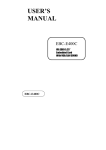
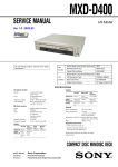
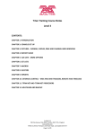
Quick start
Little Six ENGLISH
TABLE OF CONTENTS
INTRODUCTION.
3
SAFETY ADVICE
3
GENERAL INSTRUCTIONS AND GUIDELINES FOR USE
4
PARTS CHECKLIST
5
IDENTIFYING THE SCREWS, BOLTS & WASHERS
6
TOOLS REQUIRED FOR ASSEMBLY
7
ADDITIONAL EQUIPMENT THAT YOU WILL NEED (TO FLY AIRCRAFT)
7
PLANNING YOUR INSTALLATION
7
ASSEMBLING THE TOP FRAME
8
INSTALLING THE MOTORS
9
CONNECTING THE ESCS TO THE MOTORS
10
CHECKING THE DIRECTION OF ROTATION FOR YOUR MOTORS
10
OVERVIEW OF AIRCRAFT ARMS DIRECTION OF ROTATION
11
ASSEMBLY OF THE COMPLETE ARM WITH MOTOR & ESC
12
AIRCRAFT MOTOR ROTATION AND IDENTIFICATION
13
MOUNTING THE ARMS ONTO THE FRAME
14
CABLES POSITIONING
15
COG LOCATION & NAZA FLIGHT CONTROLLER INSTALLATION
16
ATTACHING THE LOWER FRAME
17
ATTACHING THE CANOPY SUPPORTS
18
ATTACHING THE LANDING SKIDS TO THE LOWER FRAME
19
ATTACHING A CAMERA TO THE FRAME USING THE CAM PLATE
20
ATTACHING THE H3-3D GIMBAL USING THE ZENMUSE MOUNTING PLATE
21
IDENTIFYING THE PROPELLER’S DIRECTION OF ROTATION
22
ATTACHING THE PROP ADAPTER AND PROPELLER ON THE MOTOR
23
ATTACHING THE CANOPY
24
INSTALLING THE BATTERY
25
CHECKS BEFORE THE FIRST FLIGHT
26
REGULAR MAINTENANCE
27
LIMITED WARRANTY
28
APPENDIX 1 – ESC MANUAL
30
2
INTRODUCTION
CONGRATULATIONS on your purchase of a SKY-HERO Little 6, we hope that it will provide you with many years
of fun and entertainment.
SKY-HERO products are designed and developed in Belgium (Europe), but distributed and supported across the
globe through a network of dealers and outlets that can provide assistance and advice.
The SKY-HERO ethos is simple; provide cool, flexible, high quality aircraft, and back all products with a fair and
reasonable support service.
OUR PHILOSOPHY
Foldable
Hidden Electronic
Oversized carbon parts
Multi-sized frames
Co-axial design
SAFETY ADVICE
# take it everywhere
# neat
# don’t fear massive payload
# choose yours
# heavy wind resistance
Smart Layout
# easy nose visibility
Few parts
# infinite possibilities
Looks beautiful
# be ready for Envy!
WARNING!
This aircraft is not a Toy!
All SKY-HERO aircraft can be considered as sophisticated leisure products, which require handling with care
and caution in order to avoid injury to yourself or others. Ensure that you fully review all of the information in
this instruction manual and familiarise yourself with the characteristics of this SKY-HERO aircraft before attempting to fly it.This instruction manual has been designed with safety in mind and is provided to help you assemble
your aircraft and to prepare it for use. Assembly of this aircraft requires basic mechanical and electrical skills
and flying this type of aircraft requires basic coordination skills and some practice.
3
GENERAL INSTRUCTIONS AND GUIDELINES
FOR USE
• The aircraft should not be flown by children and definitely not anyone under the age of 14
• Failure to follow and comply with the safety advice and recommendations in this manual, can result in serious injury
to you, others or property.
• You should always check the local laws and regulations of the country where you will operate the aircraft, to ensure
you are in compliance with them. In particular you should avoid any sensitive areas such as Military establishments,
Airports, Power stations and populated areas.
• Always keep an adequate safe distance around the aircraft, ensuring that you avoid proximity to buildings, people and
anything which is outside of your control.
• The aircraft is controlled by radio signal which can be subject to interference outside of your control, a loss of radio
contact with the aircraft puts it out of your control and could cause unpredictable results.
• Never fly the aircraft in confined or built up areas, where you might lose visibility of the aircraft.
• Never fly the aircraft in bad weather or strong winds, doing so could cause you to lose control with unpredictable
results.
• Never approach the aircraft until the propellers have stopped turning and never try to touch it whilst it is in flight.
• Keep your batteries away from children, young children could attempt to put them in their mouth with dangerous
consequences.
• Do not expose the aircraft to water, moisture or liquids.
• Do not attempt to fly the aircraft when battery power is low (including transmitter battery).
• Before each flight, make sure that all propellers are securely attached, that there is no damage to the aircraft or its
electronics and wiring.
• Always disconnect the battery power to the aircraft before turning off the transmitter and always turn the transmitter
on (checking the position of all controls) before connecting the battery
• Always following the instructions provided with your Flight Controller and any accessory equipment
such as transmitter, battery chargers etc.
4
PARTS CHECKLIST
N° DESCRIPTION
1
BUTTON HEAD PLASTIC SCREW M3 X 10MM
2
MAIN FRAME LITTLE 6 UP
3
HALF FRAME SPACER
4
MOTOR (SKY HERO X2806 950KV*)
5
MOTOR FRAME BLACK
6
WASHER M3
7
BUTTON HEAD SCREW M3 X 6MM
8
ESC (40 AMP 6S SimonK Opto*)
9
INSERT ARM BLACK
10
ARMS SET LITTLE 6 (2FR 2MID 2R)
11
HEX NUT NYLSTOP M3
12
SOCKET HEAD SCREW M3 X 10MM
13
TUBE FRONT LITTLE6
14
TUBE MIDDLE LITTLE6
15
TUBE REAR LITTLE6
16
BUTTON HEAD SCREW M4 X 40MM
17
KNURL BUTTON LONG M4
18
MAIN FRAME LITTLE 6 DOWN
19
ZENMUSE PLATE LITTLE 6
20
WASHER M4
21
HEX NUT NYLSTOP M4
22
STANDOFF LITTLE
23
LANDING SUPPORT LEFT
24
LANDING SUPPORT RIGHT
25
BUTTON HEAD SCREW M4 X 12MM
26
CAM PLATE LITTLE 6
27DAMPER
28CLIPS
29GROMET
30
CANOPY LITTLE 6
31
PROP NUT
32
PROP SHAFT WASHER
33
11’’ CLOCKWISE PROPELLER
34
11’’ COUNTERCLOCKWISE PROPELLER
35
SOCKET HEAD SCREW M3 X 8MM
36
PROP SHAFT AXIS
37
BATTERY STRAP
PART NUMBER
Q
SKH07-111
SKH03-011-U
SKH01-102
SKH04-007 (*)
SKH01-005-BK
SKH07-111
SKH07-111
SKH04-003 (*)
SKH01-004-BK
SKH03-065
SKH07-111
SKH07-111
SKH03-065
SKH03-065
SKH03-065
SKH07-111
SKH07-111
SKH03-011-D
SKH08-009
SKH07-111
SKH07-111
SKH07-111
SKH01-101
SKH01-101
SKH07-111
SKH03-013
SKH07-111
SKH07-111
SKH07-111
SKH05-055
SKH04-002
SKH04-002
SKH04-008-L6
SKH04-008-L6
SKH04-002
SKH04-002
SKH08-003
24
1
6
6
12
24
24
6
6
1
42
42
2
2
2
12
10
1
1
10
4
2
1
1
4
1
3
2
2
1
6
6
3
3
24
6
1
(*)
INCLUDED IN BIND READY VERSION
5
IDENTIFYING THE SCREWS, BOLTS & WASHERS
BUTTON HEAD SCREW M4 X 40MM
BUTTON HEAD SCREW M4 X 12MM
BUTTON HEAD SCREW M3 X 6MM
BUTTON HEAD PLASTIC SCREW M3 X 10MM
SOCKET HEAD SCREW M3 X 8MM
HEX NUT NYSLTOP M3
HEX NUT NYSLTOP M4
WASHER M3
WASHER M4
6
TOOLS REQUIRED FOR ASSEMBLY
2 mm hex wrench
2.5 mm hex wrench
3 mm hex wrench
7 mm wrench
A reamer tool (optional)
Double-sided adhesive tape
Blue threadlock (Loctite)
12 mm Heat Shrink tubing
ADDITIONAL EQUIPMENT THAT YOU WILL NEED
(to fly aircraft)
Radio Transmitter* (and compatible 6 channel or more receiver)
Lipo Battery 4S* (Capacity of 3000mAH / 65c or higher recommended)
(*)
PRODUCT AVALABLE ON WWW.SKY-HERO.COM
PLANNING YOUR INSTALLATION
Before starting to assemble your SKY-HERO aircraft, it is important to plan your build. You should check that you have
all of the parts and components that you will need. You should also think about what accessories you might want to add
to the aircraft and also where on the frame you will locate them. For example you might want to add a Camera Gimbal
or navigation lights. You need to consider how any accessories that you might add, could affect the Centre of Gravity as
well as things like which route the wiring will take. Some wires might need to be shortened whilst others might need to
be extended. One tip is (prior to starting the assembly) lay out your electronics, motors, wiring, etc against the frame and
check that there is space for everything.
If you will locate the ESCs in the arms of the Aircraft as recommended, it may be necessary to adjust the length of their
cables to avoid excessive cabling in the main body or the tubes of the frame. Remember that if you will fold the arms away
after flying, you may need some extra cable to allow for the bending of the arms.
The setup of the NAZA flight controller is not covered within this manual as full instructions can be found on the DJI
website (www.dji.com) under NAZA-M (http://www.dji.com/product/naza-m-v2). You should make sure you have access
to the manual and necessary software, in order to configure the flight controller and to carry out your pre-flight checks.
7
ASSEMBLING THE TOP FRAME
Attach the half frame spacers (3) to the upper frame (2) using the M3 x 10 mm Button Head Plastic screws (1).
Also attach the canopy bracket using M3 x 6 mm button head screws (7).
Use a small drop of Blue thread-lock on the screws.
Note: Do not over tighten the screws used for securing the plastic half frame spacers
1
2
3
8
INSTALLING THE MOTORS
Orientate the motor in the motor mount, so that the leads can pass through the hole to the tube.
Check that when the motor is in it’s correct position, it will be able to turn freely, and that if there is a clip on base of the
motor, that it is not rubbing against the hole in the middle of the motor mount.
Mount the engines (4) on their supports (5) with the 3 x 6 mm button head screws (7) and washers (6).
Identify which holes will be used to secure the motor and apply a small amount of blue Thread lock to each hole in the
bottom of the motor.
Make sure that there is no excess Thread lock that might make contact with the plastic parts as this could cause the plastic
parts of the frame to weaken and break – with dangerous consequences if the aircraft is in flight.
Note: For more information on mounting motors, you can visit the SKY-HERO channel on YouTube and watch the video
“Sky Hero How to Mount Your Motors”:
https://www.youtube.com/watch?v=1-xQFuDLJi0
4
5
6
7
* INCLUDED IN BIND READY VERSION
9
CONNECTING THE ESCs TO THE MOTORS
Connect one ESC to each motor. Initially it does not matter which of the 3 ESC cables you connect to the 3 cables from
your motor. It is best however, to connect 3 ESC cables for 3 motors one way and the other 3 ESC cables to their motors,
a different way.
8
Connect motor to ESC
4
CHECKING THE DIRECTION OF ROTATION
FOR YOUR MOTORS
Please refer to Image on next page.
Bind your Receiver to your Transmitter (in accordance with the Transmitter or Receiver instruction manual).
Ensure that none of your motors have their propellers attached, and connect each
motor to each of your ESCs (8).
Place a motor mount (5) with it’s engine securely mounted inside (but without the 2nd half of the motor mount attached),
in a secure position where it will not injure anyone or your property when it starts up. Make sure your Transmitter is switched off.
Taking one ESC & Motor combination at a time, connect the ESC signal cable to the throttle channel of your receiver,
ensure that your Transmitter Throttle control is at the lowest position and Turn on your Transmitter.
Connect your receiver to suitable power source (typically 6v, but check your receiver manual to be sure), connect your
ESC power cables to a 3s or 4s Lipo battery.
If you have not already done so, you should calibrate your ESC to your transmitter (refer to the manual of your ESC for
the method to follow) If you are using a SKY-HERO supplied ESC, see Appendix 1 in this manual for the ESC instructions.
Considering the position where the motor arm will be located on the aircraft frame, apply a small amount of throttle and
check that motor’s direction of rotation is correct in relation to the diagram in the section «Aircraft Motor rotation and
Identification».
If the motor is turning in the wrong direction, you can reverse it’s direction of rotation by swopping over any 2 (of the 3
wires) that go between the ESC and the Motor.
10
3 of your 6 motors must rotate in a clockwise direction (CW)
and the other 3 in an anti-clockwise direction (CCW).
The aircraft has 3 pairs of different sized arms (2 arms of the same size equals one pair). Within a pair, one arm must be
setup with 1 motor turning clockwise and 1 with a motor turning anti-clockwise
(see the section “Overview of Aircraft arms direction of rotation”).
Note: While you are still assembling your Aircraft, it is a good idea to place a smaller label or sticker, on the motor mount
(5) - indicating the direction. It is also worthwhile indicating a motor number (between 1- 6) on the same label. Attaching
a similar label to the ESC signal cable with the same number (between 1 - 6) will make things easier when you come to
connect the motors to your Flight Controller.
Further help can be found by watching the Video
«SKY-HERO HOW TO ASSEMBLE YOUR MOTOR MOUNTS»
on the Sky-HERO YouTube channel: https://www.youtube.com/watch?v=bvkSoewk7Mw
OVERVIEW OF AIRCRAFT ARMS DIRECTION OF
ROTATION
CCW
CW
ESC
13
14
15
Note the different hole spacing at each end of tube. The pair of holes with
the smaller space goes into the motor mount
11
ASSEMBLY OF THE COMPLETE ARM WITH
MOTOR & ESC
The carbon tube (Part No. 13/14/15) has 2 pairs of holes. One pair has a smaller gap between them;
this end of the tube should be fixed in the motor mount.
On the inside of each motor mount (5) there are two small studs, these must be orientated to coincide
with the holes that are in the carbon arms.
Fix the motor mounts on their respective arms using 3 X 10 mm (12) Socket head screws and nuts
M3 (11). Slide the arm inserts (9) into each tube.
You should ensure that the ESC power leads exit the tube from the outer edge of the tube, across
the Insert (9), and into the center of the aircraft.
Do not overtighten the 4 screws that secure the motor mount to the carbon tube. A small space must
be visible between the two motor mounts halves
12
8
9
10
5
11
Make sure that these 3 nuts M3 (11) are orientated correctly to fit inside the hole and ensure that they are fully
inserted into the motor mount hole. If the nuts are not
fully inserted, the screw will not connect and the two
motor mount halves will not be securely connected
12
AIRCRAFT MOTOR ROTATION AND
IDENTIFICATION
CW
CCW
CCW
CW
CW
CCW
13
MOUNTING THE ARMS ONTO THE FRAME
Returning to the upper chassis that you partly assembled in the section
«Assembling the Top Frame»
, attach all arms in accordance with the direction of rotation of the motors displayed on the diagram in section
«Aircraft Motor rotation and Identification»
Ensure that all cables exit their carbon tubes, passing across the arm insert (see next page) and into the center of the
aircraft.
Do not forget to leave enough loose cable to allow the arms to be folded back
FRONT ARMS:
Align the holes in the chassis with the plastic insert, and use a M4x40mm button head screw (16) into hole A and temporarily secure with a M4 knurl button long (17).
CENTRAL ARMS:
Align the holes as before and use a M4x40mm button head screw (16) into hole B and loosely secure with a M4 knurl
button long (17).
Rear arms :
Align the holes as before and use a M4x40mm button head screw (16) into hole B and loosely secure with a M4 knurl
button long (17).
16
17
Note:
• Do not fully tighten the M4 knurled nuts (17), until you have attached the lower frame (see later section)
• Handle the chassis with care because until both the top and bottom frame are attached, the weight of the arm, equipped their engines on a single chassis frame, can cause it to flex
14
CABLES POSITIONING
9
15
CoG LOCATION & NAZA FLIGHT CONTROLLER
INSTALLATION
If you are using the NAZA Flight Controller with GPS, the diagram below provides some guidance on where to locate the
standard components
GPS
LED
NAZA V2
PMU
18
LED position on the lower
framer
CoG
Center of gravity
2
Suitable location
GPS position
16
ATTACHING THE LOWER FRAME
18
1
If you want to install additional electronics between the upper and lower frame you should install them securely now,
before proceeding to the next step
If you previously attached the M4 knurl button long nuts (17), remove them in order to attach the lower frame and then
secure the lower frame using the M3 x 10 mm Button Head screws (1) to secure the frame onto the Half Frame Spacers
(3).
Note: Do not over tighten the screws
21
17
22
Finish assembly of the lower frame by using the M4 knurl button long nuts (17) and the M4 Hex Nut Nylstop (22) to
secure the frame ( using M4 washers (21) as indicated in the adjacent diagram).
17
ATTACHING THE CANOPY SUPPORTS
23
16
18
ATTACHING THE LANDING SKIDS TO THE
LOWER FRAME
If you plan to use a Camera or install a Gimbal, below the aircraft,
you will need to install the landing skids.
Otherwise if you prefer a sleeker look, you can leave the landing skids off.
Secure the landing skids using 4 x Button Head Screws M4 x 12MM and 4 x Knurl Button Long M4.
26
18
17
24
25
19
ATTACHING A CAMERA TO THE FRAME USING
THE CAM PLATE
The Little 6 comes with a vibration isolating camera mount (27) that allows you to attach a Go Pro Hero type camera to
the underside of the aircraft.
To use the mount insert the isolation dampers (28) into their holes in the lower frame, then attach the camera mount (27)
to the other end of the isolation dampers.
27
28
28
Note: the strap or bracket attaching the Go Pro to the mounting
plate is not included in the package
27
20
ATTACHING THE H3-3D GIMBAL USING THE
ZENMUSE MOUNTING PLATE
The Little 6 is supplied with a mounting plate (20) to assist in mounting the Zenmuse H3-3D Gimbal onto the aircraft.
(Refer to the diagram below ).
20
11
ZENMUSE H3-3D
Screws supplied
with gimbal
Assemble your Gimbal and attach it to the lower plate using the Zenmuse mounting plate (20) using the screws provided
with the Zenmuse and the nuts M3 (11).
Attach the mounting plate to the lower frame using the Knurls button long and the arms screws.
21
IDENTIFYING THE PROPELLER’S DIRECTION OF
ROTATION
$
$
Always place the convex side of
the propeller to the top
Trailing edge
(back of the propeller)
Leading edge (front of the propeller)
&283($$
(&+(//(
22
ATTACHING THE PROP ADAPTER AND PROPELLER ON THE MOTOR
Install the prop shafts (supplied with your motors) on each motor. Depending on the diameter of the prop shaft, you might
need to use an insert or washer that comes with your propellers to ensure a tight fit to the shaft and proper alignment.
Depending on the diameter of the prop shaft, you might need to use an insert or washer that comes with your propellers
to ensure a tight fit to the shaft and proper alignment.
We recommend that you use a prop balancer to balance your propellers, then connect the propellers on each motor –
(ensuring that their direction of rotation corresponds to the diagram on page 11).
32
33
36
34
AND
35
4
37
23
ATTACHING THE CANOPY
Insert the grommets (30) into the two canopy holes and attach the canopy to the frame,
securing it using the clips (29).
30
31
23
29
24
INSTALLING THE BATTERY
Insert your battery as shown, securing it with the battery strap (38).
Ensure that the aircraft is reasonably well around it’s CoG point.
Insert battery here
38
25
CHECKS BEFORE THE FIRST FLIGHT
OPERATE YOUR AIRCRAFT SAFELY
Refer to and follow all safety precautions mentioned in the “General Instructions and Guidelines for use”
section of this manual.
Ensure that you always turn on your transmitter before connecting the aircraft battery power. After flying, make sure that
you always disconnect the aircraft battery before turning off the transmitter.
NAZA FLIGHT CONTROLLER
If you are using the NAZA Flight Controller, follow the Naza Flight Controller pre flight checks
(pay attention to indications that you may need to Calibrate your Flight Controller before flight).
Full instructions for the NAZA Flight Controller can be found on the DJI website (www.dji.com)
under NAZA-M (http://www.dji.com/product/naza-m-v2).
You should make sure you have access to the manual and necessary software, in order to configure the flight controller.
FLIGHT TEST YOUR LITTLE 6
Fly 5 minutes in hover and then land your aircraft.
Disconnect the battery and check the temperature of the engines and tubes: they may be warm, but must not be hot.
Recharge the battery and check the capacity (mAh) that your charger puts back into the battery. This mah value will correspond to the power consumption of your Little6 during the 5 minute flight.
CALCULATING YOUR IDEAL FLIGHT TIME
• If for example: you use a 5000 mAh battery and after 5 minutes of hovering, you put it on charge and 2000 mAh of
power is put back into the battery.
• To translate this into your ideal flight time, you need to divide the capacity of the battery (5000mAh) by recharged
mAh amount (2000mAh) and multiply the result by the duration of your flight in minutes (5 min).
• Example: 5000/2000 = 2.5 x 5 min = 12 min 30. This is your approximate maximum flight time.
• For safety reasons, we would advise that you do not fly beyond more than 80% of the maximum flight time.
• In our example, if you fly for about 10 minutes, you should have enough power to return and land without risking
damage to your battery.
If your transmitter has a countdown or a timer function, it is advisable to use it! Windy conditions and cold temperatures
can adversely affect your max flight time.
Note : You need to calculate the flight time individually for each type/specification of battery that you have.
26
REGULAR MAINTENANCE
• Lubricate the motor bearings every 10 flights with specific oil for bearings.
• Replace your motors after 100 flights or in case of any unusual noises.
• Check the condition of your propellers and ensure that they are securely mounted.
• Check motors are secure on their motor mounts.
• Check the arms and knurled nuts to verify they are secure.
• Check that the motor mounts have not rotated on the arms.
• Check that there are no damaged parts, cables or electronics.
27
LIMITED WARANTY
WARRANTY AND REPAIRS
Warranty requests will be processed only with an original proof of purchase from an authorized SKY-HERO dealer,
showing the name of the buyer as well as the date of purchase. If the case for Warranty is confirmed, the product will be
repaired. Only SKY-HERO will be able to take the decision about repairing the product.
In case of paid repairs, we establish a quote that we pass to your dealer. The repairs will be carried out only after we have
received confirmation from the dealer. The price of the repairs must be paid to the dealer. For chargeable repairs, we
charge at least 30 minutes of work in the workshop as well as forwarding fees. In the absence of an agreement for the
repairs within a period of 90 days, we reserve the option to destroy the product or use it otherwise.
WARRANTY PERIOD
Exclusive Warranty: SKY-HERO ensures the product purchased (the «Product») will be free from defects in improper
materials and workmanship (subject to the terms set forth herein) in accordance with the official documentation for the
applicable Warranty Period from the date of retail purchase. Warranty is governed by and construed under the laws of the
country in which the original product purchase took place. The warranty period is 6 months and the duration of warranty
obligation of 18 months at the expiration of the warranty period.
WARRANTY LIMITATIONS
(a) The Warranty applies only to the original purchaser and is not-transferable. The Purchaser’s legal rights consists of
repair or exchange under this Warranty. The Warranty applies only to products purchased from an authorized dealer of
SKY-HERO products. Sales via third parties are not covered by this Warranty. Your “Little 6” is covered by this Warranty
under the specified Warranty period starting from the original purchase date. Proof of the original purchase date is required for Warranty service. SKY-HERO reserves the right to modify the provisions of this Warranty without prior notice and
then revokes the existing Warranty provisions.
(b) SKY-HERO assumes no Warranty as to the merchantability of the product capabilities and the physical form of the
user for a given use of the product. It is the sole responsibility of the Buyer to verify whether the product corresponds to
its capacity and intended use.
(c) Buyer’s rights: SKY-HERO will inspect the product and in its sole discretion repair or replace it with a refurbished
product or functional equivalent. These are the Buyer’s exclusive legal rights of recovery where a defect is found. The
decision made by SKY-HERO shall be final and binding upon you.
SKY-HERO may refuse to provide inspection, repair or replacement service for products that are out of
Warranty and will charge fees if these services are provided for out-of-warranty products.
Damage or alteration of Warranty, quality or authenticity stickers, and/or product serial or electronic numbers, unauthorized repair or modification, or any physical damage to the product or evidence of opening
or tampering with the product casing will also avoid this Warranty.
ATTENTION:
We only carry out and cover repairs (under valid warranty) to electronic components and engines.
Repairs to anything else, must therefore be carried out by the purchaser themself.
28
DAMAGE LIMITATION
To the extent permitted by applicable law, SKY-HERO disclaims any infringement, consequential, indirect, or incidental
damages, including but not limited to lost profits, lost business investments, lost goodwill, or damages.
In addition, SKY-HERO shall also not be responsible for failure or any third party equipment, even if
SKY-HERO has been advised of the possibility. SKY-HERO shall not be liable for any personal injury or death or any loss
or damages to property arising from the product used in a situation in which personal injury or deaths is likely occur.
If you are not ready, as a buyer, to accept the liability associated with the use of the product, we ask you to return the
complete product to the vendor, unused and in its original packaging.
QUESTIONS, ASSISTANCE AND REPAIRS
Without consulting SKY-HERO directly, your local dealer or point of sale can perform an estimate as to your eligibility for
repair under our Warranty. Please, in such a case, contact your dealer who will agree with
SKY-HERO of an appropriate decision, to assist you as soon as possible.
REPAIRS UNDER WARRANTY
If your product requires maintenance or repair, please contact either your dealer or SKY-HERO directly.
Package the product carefully. Please note that the original packing carton does not, as a general rule, protect the product
from damage that can occur during transport. Use a Parcel delivery service that provides tracking of shipment as well as
sufficient carriage insurance, as SKY-HERO can accept no responsibility for the product until it has been received and
signed for by one of our employees.
Please ensure that you provide a valid proof of purchase, detailed reasons for the return as well as a list of all items
included within your parcel. We also need a full return mailing address together with phone number (please provide the
international dialling code as necessary) and a contact e-mail address in case of questions.
29
APPENDIX 1 - ESC MANUAL
30
SKY-HERO
42, rue des Vétérinaires,
1070 Anderlecht. Belgique.
[email protected]
+32(0)23301845
31