1
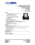
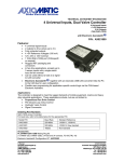
TECHNICAL DATASHEET #TDAX100700
Stepper Motor Drive
1 Analog Input, 1 Frequency/PWM Input
Motor Output (2A), Digital Output (5A)
12V or 24VDC
+5V Reference
1 CAN (SAE J1939)
with Electronic Assistant®
P/N: AX100700
Rugged and Programmable Motor Drive for 2-Phase Stepper Motors
Features:
•
•
•
•
•
•
•
•
•
•
•
•
•
•
•
•
Simple and accurate control of the levels, waveforms, timing and
phase-shifts of the current for a two phase stepper motor via SAE
J1939 command messages
1 analog input for voltage or current (user selectable) can act as a
command source for a run-time parameter, feedback in a PID
control loop or as an E-stop command
+5V reference voltage to power a sensor or potentiometer
1 Frequency or PWM input for inductive or active sensors (user
selectable)
12V/24VDC input power (nominal)
Surge protection, over and under voltage protection
Motor output is 2A per phase for a Stepper Motor.
Motor direction is selectable
1 sinking digital output (up to 5A) for a relay, brake or other load
1 CAN (SAE J1939)
CANopen® module available on request
Open or closed loop motor drive control logic (user selectable)
Highly programmable to meet various application-specific requirements
Electronic Assistant®
runs on a Windows operating system for user configuration and
programming. An Axiomatic USB-CAN converter links the PC to the CAN bus.
Fault detection over CAN bus
Rugged packaging and connectors
Applications:
•
Construction Equipment, Mobile Equipment, Material Transport Vehicles, On-road Vehicles (Bus)
Ordering Part Numbers:
SAE J1939 Stepper Motor Drive: AX100700
Accessories:
Mating Plug Kit: PL-DTM06-12SA-12SB
(The KIT is comprised of: DTM06-12S, DTM06-12SB, 2 W12S and 24 contacts. The Axiomatic stock # is FG-IOCTRL-19.)
AX070502 Configuration KIT includes the following.
USB-CAN Converter P/N: AX070501
1 ft. (0.3 m) USB Cable P/N: CBL-USB-AB-MM-1.5
12 in. (30 cm) CAN Cable with female DB-9 P/N: CAB-AX070501
AX070502IN CD P/N: CD-AX070502, includes: Electronic Assistant® software; EA & USB-CAN User Manual
UMAX07050X; USB-CAN drivers & documentation; CAN Assistant (Scope and Visual) software & documentation;
and the SDK Software Development Kit.
NOTE: To order this kit, you need only to specify P/N: AX070502.
Block Diagram
The controller belongs to a family of Axiomatic smart controllers with programmable internal architecture. This provides
users with flexibility, allowing them to build their own custom controller with a required functionality from a set of predefined
internal functional blocks using the PC-based Axiomatic Electronic Assistant® software tool. Application programming is
performed through the CAN interface, without disconnecting the controller from the user’s system.
TDAX100700
2
Technical Specifications:
Input Specifications
Power Supply Input - Nominal
Reverse Polarity Protection
Surge Protection
Under-voltage Protection
Over-voltage Protection
Analog/Digital Input
Frequency Input
Signal Grounds
Input Impedance
12V or 24VDC nominal (9…32 VDC power supply range)
Provided
Provided
Provided, software reaction
Provided, software reaction
1 Analog/Digital input, user configurable
•
Voltage
•
Current
•
Digital (active high or active low)
Inputs are sampled every 1 msec.
Protected against shorts to GND or +Vcc
Accuracy: +/- 1% over range
Resolution: 1mV or 1uA, depending on type
1 Frequency or PWM, for inductive or active sensors
User configurable for sampling range: 0.5 Hz to 50Hz; 10Hz to 1kHz; or 100Hz to
10 kHz
Can be configured as active high or low digital input
Inputs are sampled every 1 msec.
Protected against shorts to GND or +Vcc
Accuracy: +/- 1% over range
Resolution: 0.01 Hz or 0.1 Hz or 1Hz, depending on measuring range. 0.1% for
PWM input
2 Analog GND (Input and +5Vref)
1 Frequency GND
0-5V @ 1MOhm
0-20 mA @ 130 Ohms
Frequency/PWM @ 10 KOhm pullup or pulldown
Output Specifications
Output to Motor
Allegro DMOS Microstepping Driver, A3979
Maximum 2A per phase for a Stepper Motor
Some overcurrent protection is provided by the drive chip up to 2.5A.
Motor Disable
Motor Direction
Thermal Protection
Digital Output
Reference Voltage
User has full access to all the chip’s features via CAN messages.
Motor can be disabled in a variety of ways, including “Motor Mode”, and “E-Stop”
input, or when an error is detected.
Motor Direction can be user selected for Clockwise or Counter-Clockwise Drive.
Refer to the User Manual for details.
Thermal protection is built-in to driver chip.
1 sinking (switched to GND) output for up to a 5A load (relay, brake or other load)
+5V, 10 mA is available to power a sensor or potentiometer
and is referenced to Analog GND
General Specifications
Microprocessor
STM32F103, 32-bit at 72MHz
Standard embedded software is provided.
The stepper drive is a highly programmable controller, allowing the user to
configure it for their application. Its sophisticated control algorithms allow for open
or closed loop drive of the motor. All I/O on the unit are inherently independent from
one another, but can be programmed to interact in a large number of ways. All
configurable parameters are user selectable using the Electronic Assistant®.
Motor Drive Logic
Diagnostics
TDAX100700
There are 2 types of function blocks associated with the stepper motor logic and
drive.
Stepper Drive Values: Default run-time values, ranges for linear controls
Stepper Drive Controls: Selection of control sources for all the run-time variables
associated with the stepper and output drive
Up to 15 independent CAN Receive messages can be read from a J1939 network
to control the various run-time variables associated with the stepper drive.
Up to 10 independent CAN Transmit messages can be sent to a J1939 network for
system diagnostics and feedback.
Each input and output channel can be configured to send diagnostic messages to
the CAN network if the I/O goes out of range. Diagnostic data is stored in a nonvolatile log.
3
Additional Fault Feedback
There are several types of faults that the controller will detect and provide a
response: phase current winding problems; power supply undervoltage and
overvoltage; and lost communication. They can be sent to the CAN bus.
The Electronic Assistant® for Windows operating systems comes with a royaltyfree license for use on multiple computers.
It requires an USB-CAN converter to link the device’s CAN port to a Windowsbased PC. An Axiomatic USB-CAN Converter AX070501 is available as part of
the Axiomatic Configuration KIT.
CAN User Interface
Quiescent Current Draw
Weight
Operating Conditions
Storage Temperature
Protection
Packaging and Dimensions
P/N: AX070502, the Axiomatic Configuration KIT includes the following.
USB-CAN Converter P/N: AX070501
1 ft. (0.3 m) USB Cable P/N: CBL-USB-AB-MM-1.5
12 in. (30 cm) CAN Cable with female DB-9 P/N: CAB-AX070501
AX070502IN CD P/N: CD-AX070502, includes: Electronic Assistant® software;
EA & USB-CAN User Manual UMAX07050X; USB-CAN drivers & documentation;
CAN Assistant (Scope and Visual) software & documentation; and the SDK
Software Development Kit.
32.88 mA @ 12Vdc
0.55 lbs. (0.25 kg)
-40 to 85 °C (-40 to 185 °F)
-55 to 125 °C (-67 to 257°F)
IP67, Unit is conformal coated in the housing.
High Temperature Nylon housing - Deutsch IPD PCB Enclosure (EEC-325X4B)
4.62 x 5.24 x 1.43 inches 117.42 x 133.09 x 36.36 mm
(W x L x H excluding mating plugs)
Dimensional Drawing
Mounting
Mounting holes sized for ¼ inch or M6 bolts. The bolt length will be determined by
the end-user’s mounting plate thickness. The mounting flange of the controller is
0.63 inches (16 mm) thick.
If the module is mounted without an enclosure, it should be mounted vertically with
connectors facing left and right to reduce likelihood of moisture entry.
The CAN wiring is considered intrinsically safe. The power wires are not
considered intrinsically safe and so in hazardous locations, they need to be
TDAX100700
4
located in conduit or conduit trays at all times. The module must be mounted in an
enclosure in hazardous locations for this purpose.
No wire or cable harness should exceed 30 meters in length. The power input
wiring should be limited to 10 meters.
All field wiring should be suitable for the operating temperature range.
Network Termination
Electrical Connections
Install the unit with appropriate space available for servicing and for adequate wire
harness access (6 inches or 15 cm) and strain relief (12 inches or 30 cm).
It is necessary to terminate the network with external termination resistors. The
resistors are 120 Ohm, 0.25W minimum, metal film or similar type. They should
be placed between CAN_H and CAN_L terminals at both ends of the network.
Deutsch DTM series 24 pin receptacle (DTM13-12PA-12PB-R008)
Mating plug: Deutsch DTM06-12SA and DTM06-12SB
with 2 wedgelocks (WM12S) and 24 contacts (0462-201-20141).
20 AWG wire is recommended for use with contacts 0462-201-20141.
Use dielectric grease on the pins when installing the controller.
Typical Connections
Grey Connector
Pin #
1
2
3
4
5
6
7
8
9
10
11
12
Function
No Connection
CAN Shield
No Connection
Frequency GND
+5V Reference GND (AGND)
Analog GND (AGND)
Analog Input (Voltage/Current 1 or Din1)
+5V Reference (up to 10mA)
Frequency Input
(Frequency/PWM 1 or Din2)
No Connection
CAN Low
CAN High
TDAX100700
Black Connector
Pin #
1
2
3
4
5
6
7
8
9
10
11
12
Function
Phase 1, A+
Phase 2, B+
Digital Output + (+Vcc)
Frame GND (external connection)
Battery Battery +
Battery +
Battery Frame GND (external connection)
Digital Output – (up to 5A)
Phase 2, BPhase 1, A-
5
Control Logic
The Stepper Motor Drive is designed to give the user full access to the 2A drive control chip
A3979 via J1939 command messages. It allows for simple and accurate control of the levels,
waveforms, timing, and phase-shifts of the current for a two phase stepper motor.
The drive allows the user to set the default values for the stepper motor using the Axiomatic
Electronic Assistant ®
. It also allows the user to set the default targets and ranges for the runtime variables such as the step rate the motor is to run at, or the number of steps the motor is to
take before holding.
A unique feature of the drive is that not only are the run-time variables accessible through EA, but
they can also be independently controlled by J1939 messages received while the unit is
operational. This means that while the EA tool is used for initial setup and configuration, all the
drive values can be changed as needed without it.
The default configuration for the drive is to be a purely reactive control based on the command
data received from J1939 messages. However, it does have more sophisticated logic supported
for more complex controls. Contact Axiomatic for application-specific programming.
The “off-the-shelf” logic blocks supported by the drive, and selectable by the user, are:
a) Automatic PID control of the direction and step rate when the “Motor Mode” is selected to
be controlled by the “PID Control Function” block.
b) Diagnostic detection, reaction and feedback
c) Up to five acceleration/deceleration profiles that can be setup using EA, then selected
during operation via a CAN message.
d) Automatic resetting of the “Number of Steps” command so that the controller can simply
send the same CAN message again to step the same number of steps.
The drive also has two inputs that could be used as the command source for a run-time
parameter, rather than a CAN message. Alternatively, the inputs could be used for feedback in a
PID control, or as simple digital controls, for example to E-Stop the device. Lastly, they could
independently be sent to the J1939 network as input data for another device on the CAN bus.
Lastly, the drive has a single digital output, capable of sinking up to 5A, to drive a relay, brake or
other load in a system. By default, the output is controlled by a CAN message received from the
J1939 network, but it too could be controlled by one of the inputs instead. The output can be setup
for a simple on/off response, or to blink indicating a fault has been detected by the drive.
Note: CANopen® is a registered community trade mark of CAN in Automation e.V.
Specifications are indicative and subject to change. Actual performance will vary depending on the application and
operating conditions. Users should satisfy themselves that the product is suitable for use in the intended application. All our
products carry a limited warranty against defects in material and workmanship. Please refer to our Warranty, Application
Approvals/Limitations and Return Materials Process as described on www.axiomatic.com/service.html.
Form: TDAX100700-07/16/12
TDAX100700
6