1
Embedded Solutions
20F210-00 E5 – 2013-04-26
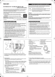
F210 – 3U CompactPCI®
GSM/GPS/UART Interface
Configuration example
User Manual
®
F210 – 3U CompactPCI® GSM/GPS/UART Interface
F210 – 3U CompactPCI® GSM/GPS/UART Interface
The F210 is a rugged single Eurocard CompactPCI® GSM/GPS/UART interface
that needs only one slot on the CompactPCI® bus.
The board is equipped with a GSM-R device that is used in rolling stock and
commercial vehicles like buses or trucks. GSM-R was specified to support train
safety and is introduced at the UIC organization as EIRENE (European Integrated
Railway radio Enhanced NEtwork) project. The F210 supports the EGSM 900 and
GSM 1800 frequency bands.
A separate GPS device is implemented on the F210 to combine the receiving
function of any kind of positioning data with the transmitting possibilities of a
mobile phone. The highly sensitive GPS receiver supports 20-channel GPS
technology, and is capable of acquisition and tracking in very low signal-strength
environments. This allows effective and reliable operation in all scenarios.
The GPS and GSM units are optically isolated from all other parts of the board.
In addition to the GPS and GSM functionality the F210 offers two SA-Adapter™
slots for serial interfaces with RS232 or RS422 or RS485 line drivers, with or
without isolation.
As an option, another three SA-Adapters™ can be connected to the F210 for userdefined functions like even more serial interfaces (synchronous/asynchronous) and/
or fieldbus interfaces like CAN bus or IBIS. These user-defined functions can be
implemented as IP cores in an onboard FPGA.
Robust Reverse SMA connectors provide the physical interface to the external GSM
and GPS antennas.
The F210 is screened for extended operation temperature and conformally coated
for use in harsh and mobile environments.
MEN Mikro Elektronik GmbH
20F210-00 E5 – 2013-04-26
2
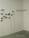
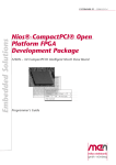
Block Diagram
Block Diagram
Isolation
Front panel 4 HP
Antenna
Antenna
GSM‐R
Controller
F
SDRAM
(option)
GPS
Controller
F
UART TTL
F
SA
B
FPGA
UART TTL
SA
F
SA
F
SA
F
SA
B
User‐defined
F
Front connector
B
On‐board
connector
SA
SA‐Adapter™
Second front panel
(+ 4 HP)
User‐defined
B
User‐defined
CompactPCI® J1
F
Options
MEN Mikro Elektronik GmbH
20F210-00 E5 – 2013-04-26
3
Technical Data
Technical Data
GSM-R Interface
• GSM-Rail: Global System for Mobile Communications – Railway
• Frequency bands
- EGSM 900, GSM 1800
- Compliant to GSM Phase 2/2+
• GSM class: Small MS
• Transmit power:
- Class 4 (2 W) at EGSM 900
- Class 1 (1 W) at GSM 1800
• GPRS connectivity
- GPRS multi-slot class 10
- GPRS mobile station class B
• Data Services
- GPRS data downlink transfer: max. 85.6 kbit/s
- GPRS data uplink transfer: max. 42.8 kbit/s
- Support of PAP (Password Authentication Protocol) and CHAP (Challenge
Handshake Authentication Protocol) for PPP connections
- Support of PBCCH (Packet Switched Broadcast Control Channel) for
enhanced GPRS performance
- CSD transmission rates: 2.4, 4.8, 9.6, 14.4 kbit/s, non-transparent, V.110
- WAP compliant
- Internet services: TCP, UDP, HTTP, FTP, SMTP, POP3
• SMS
- MT, MO, CB, Text and PDU mode
- SMS storage: SIM card plus 25 SMS locations in the mobile equipment
- Transmission of SMS alternatively over CSD or GPRS (user-defined)
- MMS compliant
• Fax: Group 3, Class 2
• Onboard SIM card interface
- Supported SIM card: 3 V
• Coding scheme CS 1, 2, 3, 4
• Optical isolation: 1 kV DC
• One antenna connector at front panel
- For the use of an external antenna
- Rugged screw connection
• Please note that MEN does not offer SIM cards or mobile telephony contracts!
MEN Mikro Elektronik GmbH
20F210-00 E5 – 2013-04-26
4
Technical Data
GPS Interface
•
•
•
•
•
•
•
•
•
•
•
•
•
Board Revision < R01
12-parallel-channel GPS (Global
Positioning System) receiver
GPS Band/Code: L1 frequency,
C/A code
Integrated TCXO, RTC
Accuracy: 5 m 2DRMS
Time To First Fix (TTFF):
- Cold start: 50 s (average)
- Warm start: 35 s (average)
- Hot start: 2.6 s (95%)
Sensitivity:
- Acquisition (unaided): -139 dBm
- Acquisition (Hi-Sensitivity):
-150 dBm
- Tracking: -152 dBm
GPS modes
- Autonomous
- MS-based (AGPS)
AGPS standards supported:
TS 04.31, ETSI TS 101 109
Protocol: NMEA 0183
•
•
•
•
•
•
•
•
Board Revision >= R01
20-parallel-channel GPS (Global
Positioning System) receiver
GPS Band/Code: L1 frequency,
C/A code
Integrated TCXO, RTC
Horizontal accuracy: better than
2.1 m (CEP) 5.2 m 2dRMS
Time To First Fix (TTFF):
- Cold start: 34 s typ.
- Warm start: 32 s typ.
- Hot start: 0.5 s typ.
Sensitivity:
- Acquisition: -155 dBm
- Navigation: -157 dBm
- Tracking: -159 dBm
GPS modes
- TricklePower™ mode for power
saving
- Push-To-Fix™ mode
Protocol: NMEA 0183
- SiRF® binary messages:
altitude, longitude, elevation,
velocity, heading, time, satellite
tracking status, command/control messages
- SiRF® binary interface: raw data
Antenna voltage supervision
3GPP compliance
Optical isolation: 1 kV DC
One antenna connector at front panel
- For the use of an external active antenna
- Rugged screw connection
UARTs
• Two channels
• Accessible via onboard connectors
• Physical interface at front panel using SA-Adapters™
- Two SA-Adapters™ can be directly plugged within 4HP
- Different physical layers depending on SA-Adapter™: RS232, RS422,
RS485 with or without optical isolation
- SA-Adapters™ to be ordered separately
• Data rates up to 2 Mbit/s
• 60-byte transmit/receive buffer
• Handshake lines: full support; lines depend on SA-Adapters™
MEN Mikro Elektronik GmbH
20F210-00 E5 – 2013-04-26
5
Technical Data
Front Connections
• Two Reverse SMA antenna connectors
• Two cut-outs for SA-Adapters™
FPGA
• Standard factory FPGA configuration:
- Main bus interface
- 16Z057_UART – UART controller (controls in-system GSM-R/GPS
communication and UARTs)
- 16Z045_FLASH – Flash interface
• The FPGA offers the possibility to add customized I/O functionality. See FPGA.
CompactPCI® Bus
•
•
•
•
Compliance with CompactPCI® Core Specification PICMG 2.0 R3.0
Peripheral slot
32-bit/33-MHz PCI-to-PCI bridge
V(I/O): +3.3 V
Electrical Specifications
• Supply voltage/power consumption:
- Depends on mounted SA-Adapters™ and used functions
- +5 V (-3%/+5%), 1900 mA max.
- +3.3 V (-3%/+5%), 850 mA max.
Mechanical Specifications
• Dimensions: conforming to CompactPCI® specification for 3U boards
• Front panel:
- 4HP with ejector
- 3U single-slot front panel for two antenna and up to two UART connectors
• Weight: 170 g
Environmental Specifications
• Temperature range (operation):
- -40..+85°C for all functions except GSM-R (screened)
- GSM-R component only operable in -20..+70°C range (auto on/off)
- Airflow: min. 10 m³/h
• Temperature range (storage): -40..+85°C
• Relative humidity (operation): max. 95% non-condensing
• Relative humidity (storage): max. 95% non-condensing
• Altitude: -300 m to + 3000 m
• Shock: 15 g/11 ms
• Bump: 10 g/16 ms
• Vibration (sinusoidal): 2 g/10..150 Hz
• Conformal coating (standard)
MEN Mikro Elektronik GmbH
20F210-00 E5 – 2013-04-26
6
Technical Data
MTBF
• 189 239 h @ 40°C according to IEC/TR 62380 (RDF 2000)
Safety
• PCB manufactured with a flammability rating of 94V-0 by UL recognized
manufacturers
EMC
• Tested according to EN 55022 (radio disturbance), IEC1000-4-2 (ESD) and
IEC1000-4-4 (burst)
Software Support
• Driver software for Windows®, Linux, VxWorks®
• For more information on supported operating system versions and drivers see
online data sheet.
MEN Mikro Elektronik GmbH
20F210-00 E5 – 2013-04-26
7
Configuration Options
Configuration Options
Interface configuration
• Also available with GSM only or GPS only
• Also available with standard GSM instead of GSM-R
GSM Interface
• GSM 850 / GSM 1900 support
- For operation in USA and Canada
- Through different GSM component
- Without railway qualification
Additional user-defined functions
• I/O functionality customizable in FPGA
• Three additional serial interfaces
- Three additional SA-Adapters™ can be added within 8HP using a second
front panel
- For user-defined interface functions, e.g. CAN bus, IBIS, ...
• Nios® soft core implementation possible
- With up to 16 MB SDRAM
- For onboard intelligence
• See also FPGA
Mechanical
• For user-defined functions customized front panels are available on request.
Cooling Concept
• Also available with conduction cooling in MEN CCA frame
Please note that some of these options may only be available for large volumes.
Please ask our sales staff for more information.
MEN Mikro Elektronik GmbH
20F210-00 E5 – 2013-04-26
8
FPGA
FPGA
Flexible Configuration
• Customized I/O functions can be added to the FPGA.
• It depends on the board type, pin counts and number of logic elements which IP
cores make sense and/or can be implemented. Please contact MEN for information on feasibility.
• You can find more information on our web page "User I/O in FPGA"
FPGA Capabilities
• FPGA Altera® Cyclone® II EP2C20
- 18 752 logic elements
- 239 616 total RAM bits
• Simple functional updates via software
• 2 MB Flash for FPGA configurations
• Connection
- Functions available via two onboard 10-pin I/O connectors
- SA-Adapters™ are used to realize the physical lines.
MEN Mikro Elektronik GmbH
20F210-00 E5 – 2013-04-26
9
Product Safety
Product Safety
!
Electrostatic Discharge (ESD)
Computer boards and components contain electrostatic sensitive devices.
Electrostatic discharge (ESD) can damage components. To protect the board and
other components against damage from static electricity, you should follow some
precautions whenever you work on your computer.
• Power down and unplug your computer system when working on the inside.
• Hold components by the edges and try not to touch the IC chips, leads, or circuitry.
• Use a grounded wrist strap before handling computer components.
• Place components on a grounded antistatic pad or on the bag that came with the
component whenever the components are separated from the system.
• Store the board only in its original ESD-protected packaging. Retain the original
packaging in case you need to return the board to MEN for repair.
MEN Mikro Elektronik GmbH
20F210-00 E5 – 2013-04-26
10
About this Document
About this Document
This user manual is intended only for system developers and integrators, it is not intended for end users.
It describes the hardware functions of the board, connection of peripheral devices
and integration into a system. It also provides additional information for special
applications and configurations of the board.
The manual does not include detailed information on individual components (data
sheets etc.). A list of literature is given in the appendix.
History
Issue
Date
E1
First edition
E2
Hardware revision R01 with different GPS controller 2007-09-28
E3
Chapter 1.3.1 Logical Mapping of F210 UARTs to
Operating-System Devices added
2007-11-20
E4
Added chapters 2.5.1 to 2.5.4
2010-12-13
E5
Updated Technical Data and board maps
2013-04-26
MEN Mikro Elektronik GmbH
20F210-00 E5 – 2013-04-26
Comments
2007-05-16
11
About this Document
Conventions
This sign marks important notes or warnings concerning the use of voltages which
can lead to serious damage to your health and also cause damage or destruction of
the component.
!
italics
bold
monospace
This sign marks important notes or warnings concerning proper functionality of the
product described in this document. You should read them in any case.
Folder, file and function names are printed in italics.
Bold type is used for emphasis.
A monospaced font type is used for hexadecimal numbers, listings, C function
descriptions or wherever appropriate. Hexadecimal numbers are preceded by "0x".
comment
Comments embedded into coding examples are shown in green color.
hyperlink
Hyperlinks are printed in blue color.
The globe will show you where hyperlinks lead directly to the Internet, so you can
look for the latest information online.
IRQ#
/IRQ
Signal names followed by "#" or preceded by a slash ("/") indicate that this signal is
either active low or that it becomes active at a falling edge.
in/out
Signal directions in signal mnemonics tables generally refer to the corresponding
board or component, "in" meaning "to the board or component", "out" meaning
"coming from it".
Vertical lines on the outer margin signal technical changes to the previous issue of
the document.
MEN Mikro Elektronik GmbH
20F210-00 E5 – 2013-04-26
12
About this Document
Legal Information
Changes
MEN Mikro Elektronik GmbH ("MEN") reserves the right to make changes without further notice to any products
herein.
Warranty, Guarantee, Liability
MEN makes no warranty, representation or guarantee of any kind regarding the suitability of its products for any
particular purpose, nor does MEN assume any liability arising out of the application or use of any product or
circuit, and specifically disclaims any and all liability, including, without limitation, consequential or incidental
damages. TO THE EXTENT APPLICABLE, SPECIFICALLY EXCLUDED ARE ANY IMPLIED
WARRANTIES ARISING BY OPERATION OF LAW, CUSTOM OR USAGE, INCLUDING WITHOUT
LIMITATION, THE IMPLIED WARRANTIES OF MERCHANTABILITY AND FITNESS FOR A
PARTICULAR PURPOSE OR USE. In no event shall MEN be liable for more than the contract price for the
products in question. If buyer does not notify MEN in writing within the foregoing warranty period, MEN shall
have no liability or obligation to buyer hereunder.
The publication is provided on the terms and understanding that:
1. MEN is not responsible for the results of any actions taken on the basis of information in the publication, nor
for any error in or omission from the publication; and
2. MEN is not engaged in rendering technical or other advice or services.
MEN expressly disclaims all and any liability and responsibility to any person, whether a reader of the publication
or not, in respect of anything, and of the consequences of anything, done or omitted to be done by any such person
in reliance, whether wholly or partially, on the whole or any part of the contents of the publication.
Conditions for Use, Field of Application
The correct function of MEN products in mission-critical and life-critical applications is limited to the
environmental specification given for each product in the technical user manual. The correct function of MEN
products under extended environmental conditions is limited to the individual requirement specification and
subsequent validation documents for each product for the applicable use case and has to be agreed upon in writing
by MEN and the customer. Should the customer purchase or use MEN products for any unintended or
unauthorized application, the customer shall indemnify and hold MEN and its officers, employees, subsidiaries,
affiliates, and distributors harmless against all claims, costs, damages, and expenses, and reasonable attorney fees
arising out of, directly or indirectly, any claim or personal injury or death associated with such unintended or
unauthorized use, even if such claim alleges that MEN was negligent regarding the design or manufacture of the
part. In no case is MEN liable for the correct function of the technical installation where MEN products are a part
of.
Trademarks
All products or services mentioned in this publication are identified by the trademarks, service marks, or product
names as designated by the companies which market those products. The trademarks and registered trademarks
are held by the companies producing them. Inquiries concerning such trademarks should be made directly to those
companies.
Conformity
MEN products are no ready-made products for end users. They are tested according to the standards given in the
Technical Data and thus enable you to achieve certification of the product according to the standards applicable in
your field of application.
MEN Mikro Elektronik GmbH
20F210-00 E5 – 2013-04-26
13
About this Document
RoHS
Since July 1, 2006 all MEN standard products comply with RoHS legislation.
Since January 2005 the SMD and manual soldering processes at MEN have already been completely lead-free.
Between June 2004 and June 30, 2006 MEN’s selected component suppliers have changed delivery to RoHScompliant parts. During this period any change and status was traceable through the MEN ERP system and the
boards gradually became RoHS-compliant.
WEEE Application
The WEEE directive does not apply to fixed industrial plants and tools. The compliance is the responsibility of the
company which puts the product on the market, as defined in the directive; components and sub-assemblies are
not subject to product compliance.
In other words: Since MEN does not deliver ready-made products to end users, the WEEE directive is not
applicable for MEN. Users are nevertheless recommended to properly recycle all electronic boards which have
passed their life cycle.
Nevertheless, MEN is registered as a manufacturer in Germany. The registration number can be provided on
request.
Copyright © 2013 MEN Mikro Elektronik GmbH. All rights reserved.
Germany
MEN Mikro Elektronik GmbH
Neuwieder Straße 3-7
90411 Nuremberg
Phone +49-911-99 33 5-0
Fax +49-911-99 33 5-901
E-mail [email protected]
www.men.de
MEN Mikro Elektronik GmbH
20F210-00 E5 – 2013-04-26
France
MEN Mikro Elektronik SA
18, rue René Cassin
ZA de la Châtelaine
74240 Gaillard
Phone +33 (0) 450-955-312
Fax +33 (0) 450-955-211
E-mail [email protected]
www.men-france.fr
USA
MEN Micro, Inc.
24 North Main Street
Ambler, PA 19002
Phone (215) 542-9575
Fax (215) 542-9577
E-mail [email protected]
www.menmicro.com
14
Contents
Contents
1 Getting Started . . . . . . . . . . . . . . . . . . . . . . . . . . . . . . . . . . . . . . . . . . . . . . . .
1.1 Map of the Board. . . . . . . . . . . . . . . . . . . . . . . . . . . . . . . . . . . . . . . . .
1.2 Integrating the Board into a System . . . . . . . . . . . . . . . . . . . . . . . . . .
1.3 Installing Driver Software . . . . . . . . . . . . . . . . . . . . . . . . . . . . . . . . . .
1.3.1
Logical Mapping of F210 UARTs to Operating-System
Devices . . . . . . . . . . . . . . . . . . . . . . . . . . . . . . . . . . . . . . . . .
17
17
19
19
20
2 Functional Description . . . . . . . . . . . . . . . . . . . . . . . . . . . . . . . . . . . . . . . . . .
2.1 Power Supply. . . . . . . . . . . . . . . . . . . . . . . . . . . . . . . . . . . . . . . . . . . .
2.2 GSM-R Interface . . . . . . . . . . . . . . . . . . . . . . . . . . . . . . . . . . . . . . . . .
2.2.1
SIM Card. . . . . . . . . . . . . . . . . . . . . . . . . . . . . . . . . . . . . . . .
2.2.2
Temperature Monitoring . . . . . . . . . . . . . . . . . . . . . . . . . . . .
2.3 GPS Interface. . . . . . . . . . . . . . . . . . . . . . . . . . . . . . . . . . . . . . . . . . . .
2.4 Typical Application of GSM-R/GPS in a System . . . . . . . . . . . . . . . .
2.5 UART Interfaces . . . . . . . . . . . . . . . . . . . . . . . . . . . . . . . . . . . . . . . . .
2.5.1
Configuration under Windows . . . . . . . . . . . . . . . . . . . . . . .
2.5.2
Configuration under Linux . . . . . . . . . . . . . . . . . . . . . . . . . .
2.5.3
Configuration under VxWorks . . . . . . . . . . . . . . . . . . . . . . .
2.5.4
Configuration under QNX. . . . . . . . . . . . . . . . . . . . . . . . . . .
2.5.5
Pin Assignments . . . . . . . . . . . . . . . . . . . . . . . . . . . . . . . . . .
2.5.6
Installing SA-Adapters . . . . . . . . . . . . . . . . . . . . . . . . . . . . .
2.6 Additional Interfaces . . . . . . . . . . . . . . . . . . . . . . . . . . . . . . . . . . . . . .
2.7 CompactPCI Interface . . . . . . . . . . . . . . . . . . . . . . . . . . . . . . . . . . . . .
22
22
22
22
23
23
24
25
25
25
26
26
27
28
31
31
3 FPGA . . . . . . . . . . . . . . . . . . . . . . . . . . . . . . . . . . . . . . . . . . . . . . . . . . . . . . . . 32
3.1 General . . . . . . . . . . . . . . . . . . . . . . . . . . . . . . . . . . . . . . . . . . . . . . . . 32
3.2 Standard Factory FPGA Configuration . . . . . . . . . . . . . . . . . . . . . . . . 33
4 Appendix . . . . . . . . . . . . . . . . . . . . . . . . . . . . . . . . . . . . . . . . . . . . . . . . . . . . .
4.1 Literature and Web Resources . . . . . . . . . . . . . . . . . . . . . . . . . . . . . . .
4.1.1
CompactPCI . . . . . . . . . . . . . . . . . . . . . . . . . . . . . . . . . . . . .
4.1.2
GSM-R . . . . . . . . . . . . . . . . . . . . . . . . . . . . . . . . . . . . . . . . .
4.1.3
GPS . . . . . . . . . . . . . . . . . . . . . . . . . . . . . . . . . . . . . . . . . . . .
4.1.4
SA-Adapters . . . . . . . . . . . . . . . . . . . . . . . . . . . . . . . . . . . . .
4.2 ID EEPROM . . . . . . . . . . . . . . . . . . . . . . . . . . . . . . . . . . . . . . . . . . . .
4.3 Finding out the Board’s Article Number, Revision and
Serial Number . . . . . . . . . . . . . . . . . . . . . . . . . . . . . . . . . . . . . . . . . . .
MEN Mikro Elektronik GmbH
20F210-00 E5 – 2013-04-26
34
34
34
34
34
34
35
35
15
Figures
Figure 1.
Figure 2.
Figure 3.
Figure 4.
Figure 5.
Map of the board – front panel . . . . . . . . . . . . . . . . . . . . . . . . . . . . . .
Map of the board – top view. . . . . . . . . . . . . . . . . . . . . . . . . . . . . . . . .
Quad UART instance assignment to function . . . . . . . . . . . . . . . . . . .
GSM-R: Inserting a SIM card . . . . . . . . . . . . . . . . . . . . . . . . . . . . . . .
Typical set-up of a system with F210 based GSM-R/GPS
communication . . . . . . . . . . . . . . . . . . . . . . . . . . . . . . . . . . . . . . . . . . .
Figure 6. FPGA – Block diagram (exemplary) . . . . . . . . . . . . . . . . . . . . . . . . . .
Figure 7. Labels giving the board’s article number, revision and serial number.
17
18
20
22
24
32
35
Tables
Table 1.
Table 2.
Table 3.
Table 4.
MEN Mikro Elektronik GmbH
20F210-00 E5 – 2013-04-26
PCI address map . . . . . . . . . . . . . . . . . . . . . . . . . . . . . . . . . . . . . . . . . .
Pin assignment of the 10-pin UART "X1" receptacle connector . . . . .
Pin assignment of the 10-pin UART "X2" receptacle connector . . . . .
Signal mnemonics of UART interfaces . . . . . . . . . . . . . . . . . . . . . . . .
21
28
28
28
16
Getting Started
1
Getting Started
This chapter gives an overview of the board and some hints for first installation in a
system.
1.1
Map of the Board
Figure 1. Map of the board – front panel
X2
X1
GSM
GPS
CompactPCI ®
F210
MEN Mikro Elektronik GmbH
20F210-00 E5 – 2013-04-26
17
Getting Started
Figure 2. Map of the board – top view
SA‐Adapter "X1"
GPS antenna
connector
GSM‐R
Controller
GPS
Receiver
GSM
SIM Card Slot
Ejector
1
1
GSM antenna
connector
1
1
SA‐Adapter connector
1
SA‐Adapter connector
1
1
1
SA‐Adapter "X2"
MEN Mikro Elektronik GmbH
20F210-00 E5 – 2013-04-26
3 additional interfaces (option)
1
FPGA
CompactPCI® J1
18
Getting Started
1.2
Integrating the Board into a System
You can use the following check list when installing the board in a system for the
first time.
!
Note: The F210 must not be inserted into the system slot! The system slot of every
CompactPCI system is marked by a
triangle on the backplane and/or at the
front panel.
Power-down the system.
If you want to use GSM:
- Insert a GSM SIM card into the F210’s SIM card slot. (See Figure 1,
Map of the board – front panel, on page 17 and Chapter 2.2 GSM-R
Interface on page 22.)
- Connect a suitable antenna at the front panel. (Not included in delivery.)
If you want to use GPS: Connect a suitable active antenna at the front panel.
(Not included in delivery.)
If you want to use additional UARTs: Install SA-Adapters on the F210 as
described in Chapter 2.5 UART Interfaces on page 25.
Insert the F210 into your CompactPCI system, making sure that the CompactPCI connectors are properly aligned.
Power-up the system.
You can now install driver software for the F210 GSM/GPS controllers and
UARTs.
1.3
Installing Driver Software
The F210 is supported under Windows, Linux and VxWorks. The GSM and GPS
controllers are connected to the host system via UART interfaces and will appear
accordingly in your operating system.
If you use additional UARTs on F210 using SA-Adapters, don’t confuse them with
the GSM/GPS UARTs. Since all of the standard UARTs (including GSM/GPS) are
based on the same FPGA IP cores, driver support is also the same for all UARTs.
For a detailed description on how to install driver software please refer to the
respective documentation.
You can find any driver software available for download on MEN’s website.
MEN Mikro Elektronik GmbH
20F210-00 E5 – 2013-04-26
19
Getting Started
1.3.1
Logical Mapping of F210 UARTs to Operating-System
Devices
Under some operating systems such as Linux the mapping of the GPS and GSM
UARTs may be unclear. For instance, when MEN’s native Linux UART driver
(article number 13Z025-90) is used to register the additional UARTs it is not clear if
they are to be accessed as /dev/ttyS0 or using a different device name.
The problem is that it is unknown if there are already other serial ports in the
system, like the two classic COM ports in most desktop PCs. Under Linux these are
mapped to /dev/ttyS0 and /dev/ttyS1, so when the additional serial ports on the F210
are registered they get higher device numbers.
On the other hand, MEN boards like the F14 come with no serial devices included,
so the F210’s UARTs would be consecutively numbered starting at /dev/ttyS0.
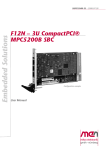
In this case it is helpful to take a look at the internal implementation of the UARTs
with respect to their position in the PCI configuration space. The figure below is a
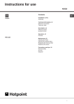
part of the IC design’s logical assignment of UARTs to functional units.
Figure 3. Quad UART instance assignment to function
FPGA
Quad UART 0
16Z057_UART
Instance 1
GPS Module
16Z057_UART
Instance 2
GSM Interface
(Full handshake)
16Z057_UART
Instance 3
GSM Interface
(CTS/RTS)
16Z057_UART
Instance 4
Quad UART 1
16Z057_UART
Instance 1
SA‐Adapter X1
16Z057_UART
Instance 2
SA‐Adapter X2
16Z057_UART
Instance 3
16Z057_UART
Instance 4
The F210 has two quad UART units, but both not fully equipped with serial ports.
To decide how each serial port can be accessed we need to know under which
addresses the CPU sees the 16Z057_UART units. The PCI address map provides
this information, its layout is defined by MEN, so the offsets are always the same.
The following table shows the relevant part of the PCI map.
MEN Mikro Elektronik GmbH
20F210-00 E5 – 2013-04-26
20
Getting Started
Table 1. PCI address map
BAR
Offset
Unit
Comment
0
0x0
Chameleon table V2
0
0x200
Quad UART 0
Memory mapped
0
0x300
Quad UART 1
Memory mapped
The offset of serial register instances within one quad UART is always 0x10, so the
offset addresses for the GPS and GSM UARTs are 0x200 and 0x210. These offsets
will always be the same regardless which address PCI BAR0 of the F210 is mapped
to.
To decide now which device name will be assigned by the kernel to each UART the
kernel messages must be watched (e.g. using the dmesg command). When the serial
port driver is loaded (module men_lx_frodo.ko loaded via modprobe) and the
UARTs on the F210 are registered, messages similar to the ones below will appear:
Nov 10 10:54:48 tcu kernel: serial8250: ttyS0 at MMIO 0xd7fff200 (irq = 10) is a 16550A
Nov 10 10:54:48 tcu kernel: serial8250: ttyS1 at MMIO 0xd7fff210 (irq = 10) is a 16550A
...
If you compare the last three numbers of each given memory mapped address
(MMIO) to the addresses given in the PCI address map above, you can clearly
identify each UART.
In this example, the GPS module will be accessible as /dev/ttyS0 and the GSM
module as /dev/ttyS1.
MEN Mikro Elektronik GmbH
20F210-00 E5 – 2013-04-26
21
Functional Description
2
Functional Description
2.1
Power Supply
Power supply is fed via the CompactPCI backplane. The board operates on +3.3 V
and +5 V.
2.2
GSM-R Interface
The GSM-Rail interface of the F210 is based on the Triorail TRM:2 modem, which
adds railway suitability to standard GSM technology (GSM = Global System for
Mobile Communications).
The F210 itself has no antenna but provides a sturdy Reverse SMA connector at the
front panel. You need to select and connect an antenna suitable for your application.
Please note that MEN does not supply antennas with the F210, since the choice
of a suitable antenna depends on your application.
The host computer can communicate with the GSM modem via a serial interface.
The communication speed is between 300 bits/s and 230 400 bits/s.
Alternative board versions with different GSM 850 / GSM 1900 support for
operation in USA and Canada are available on request. Please contact MEN’s sales
team for more information.
For technical data see Chapter Technical Data on page 4.
See also Chapter 4.1 Literature and Web Resources on page 34.
2.2.1
SIM Card
To get access to a mobile phone network you need a SIM card (subscriber identity
module) and a contract with a mobile service provider. Please note that MEN does
not provide mobile services or SIM cards!
Figure 4. GSM-R: Inserting a SIM card
SA‐Adapter "X1"
GPS
Receiver
GSM‐R
Controller
GSM
SIM Card Slot
Ejector
1
1
1
1
1
MEN Mikro Elektronik GmbH
20F210-00 E5 – 2013-04-26
22
Functional Description
Do the following to insert a SIM card:
Push the ejector and pull out the plastic SIM card holder.
Turn it around and insert the SIM card as indicated by the holder’s shape and
imprint.
Slide the SIM card holder back into the slot until it clicks into place. If it is
firmly locked, you cannot pull it out unless you push the ejector again.
2.2.2
Temperature Monitoring
The GSM-R submodule has its own temperature control mechanism. The GSM
module automatically shuts down if the ambient temperature exceeds its operation
range of -20 °C to +70 °C. This does not impede the other functions of the F210 but
adds to the board’s reliability.
2.3
GPS Interface
The GPS interface of the F210 is built around the Navman Jupiter 30 GPS receiver
module (board revisions < R01: HS110 GPS module).
The F210 itself has no antenna but provides a sturdy Reverse SMA connector at the
front panel. You need to select and connect an active antenna suitable for your
application. Please note that MEN does not supply antennas with the F210,
since the choice of a suitable antenna depends on your application.
The host computer can communicate with the GPS controller via a serial interface.
The GPS interface provides the power supply for the active antenna. The active
antenna is driven by 5 V (50 mA). As a board option, this voltage can be changed to
3.3 V or can be disabled completely. Please contact MEN’s sales team.
The GPS antenna power is limited by a polyfuse to 300 mA.
For technical data see Chapter Technical Data on page 4.
See also Chapter 4.3 Finding out the Board’s Article Number, Revision and Serial
Number on page 35.
MEN Mikro Elektronik GmbH
20F210-00 E5 – 2013-04-26
23
Functional Description
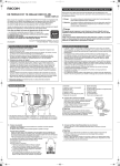
2.4
Typical Application of GSM-R/GPS in a System
MEN provides UART driver software to support communication inside the system.
You will need to select suitable further software or write your own software to
implement the requirements of your specific application.
The following figure gives you a typical on-train application of the F210.
• The GSM and GPS functions provide wireless communication.
• A host CPU may process data and may also be connected to a user terminal, if
needed.
• The F210 can handle on-train serial communication using its two standard
UARTs. It can also be configured to the user’s needs with additional interfaces or
even with a Nios processor for more sophisticated data processing.
If you are interested in customizing your F210 solution e. g. through additional
interfaces, please contact MEN’s sales team.
Figure 5. Typical set-up of a system with F210 based GSM-R/GPS communication
Gets and
processes data
from trains
Control Center
Sends/receives
data to/from
control center
Gets satellite
positioning data
GSM
GPS
F210
Handles GSM,
GPS and serial
communication
CompactPCI Bus
On-train serial
communication
Host CPU
Can display
data and lets
the user control
communication
User Terminal
Gathers data
and processes
user actions
On‐Train System
MEN Mikro Elektronik GmbH
20F210-00 E5 – 2013-04-26
24
Functional Description
2.5
UART Interfaces
The F210 offers two standard UARTs. The physical layer is realized individually for
each channel by means of SA-Adapters. Two SA-Adapters can be plugged directly
on the PCB.
You can use different types of SA-Adapters with the F210, e.g. isolated and nonisolated adapters for RS232, RS422 and RS485 interfaces. The interfaces are
accessible at the front by means of 9-pin D-Sub connectors on the SA-Adapter.
Please see the F210 data sheet for a list of available standard SA-Adapters.
The UART interfaces are controlled by an on-board FPGA (see also Chapter 3
FPGA on page 32). SA-Adapter X1 is connected to "Quad UART 1 - Instance 1"
and SA-Adapter X2 is connected to "Quad UART 1 - Instance 2".
2.5.1
Configuration under Windows
MEN’s driver installation package for Windows allows easy configuration through
the Device Manager.
To do this, open the Properties page of each F210 UART device via the Windows
Device Manager, select the Port Interface tab and choose the used physical
interface.
You can find more details on the Windows driver installation package in the F210
under Windows User Manual.
You can download the Windows driver and user manual from MEN’s website.
2.5.2
Configuration under Linux
MEN provides a Linux driver that allows to configure the interface mode and baud
rate.
You can find more details on MEN’s Linux driver software in Application Note:
Using 16Z025_UART and 16Z125_UART under Linux (21APPN009).
You can download the application note from MEN’s website.
You can download the Linux driver from MEN’s website.
The baud_base parameter must be set to 115200.
MEN’s Linux driver supports the following values for the mode parameter:
se
single ended (RS232)
df_fdx
differential, full duplex (RS422)
df_hdxe
differential, half duplex, with echo (RS485)
df_hdx
differential, half duplex, no echo (RS485)
The following examples show how to use the driver with F210.
Set SA-Adapter X1 and X2 to RS232 (e.g. SA01)
# modprobe men_lx_frodo_sw baud_base=115200
mode=se,se,se,se,se
MEN Mikro Elektronik GmbH
20F210-00 E5 – 2013-04-26
25
Functional Description
Set SA-Adapter X1 and X2 to RS422 full-duplex (e.g. SA02-01)
In order to change the settings, the driver needs to be removed first.
# modprobe men_lx_frodo_sw baud_base=115200
mode=se,se,se,df_fdx,df_fdx
The first three UART instances always have to be set to se as they are connected to
the GPS and the GSM interface. See Chapter 3.2 Standard Factory FPGA
Configuration on page 33.
!
Note: Most Linux kernels only support 4 UARTs by default. If more than 4 UARTs
are needed, the kernel parameter CONFIG_NR_8250_UARTS has to be
adjusted and the kernel has to be recompiled.
2.5.3
Configuration under VxWorks
MEN provides a VxWorks driver that provides comprehensive I/O control support
to configure the interfaces.
You can find more details on MEN’s VxWorks driver software in the driver’s
included HTML documentation.
You can download the VxWorks driver from MEN’s website.
The UART clock frequency must be set to 1843200. You can use driver function
Z25_CreateDevice or Z25_SetBaseBaud to do this.
2.5.4
Configuration under QNX
MEN provides a QNX driver that allows configuration of the interfaces through
QNX tool stty.
The stty tool together with MEN’s QNX driver provides a large number of
parameters to configure serial interfaces. MEN’s driver includes options to set the
physical interface itself. You can get details on the driver using QNX command use
devc-serz025.
You can download the QNX driver from MEN’s website.
To get details on the driver use QNX command use devc-serz025.
You can find more information on stty also on the QNX developer community website.
MEN Mikro Elektronik GmbH
20F210-00 E5 – 2013-04-26
26
Functional Description
2.5.5
Pin Assignments
Table 2. Pin assignment of the 10-pin UART "X1" receptacle connector
9
10
1
2
9
DCD1#
10
RI1#
7
DSR1#
8
CTS1#
5
DTR1#
6
RTS1#
3
TXD1
4
RXD1
1
GND
2
+5V
Table 3. Pin assignment of the 10-pin UART "X2" receptacle connector
9
10
1
2
9
DCD2#
10
RI2#
7
DSR2#
8
CTS2#
5
DTR2#
6
RTS2#
3
TXD2
4
RXD2
1
GND
2
+5V
Connector types:
• 10-pin receptacle, 2.54mm pitch, for SA-Adapter connection
Mating connector:
• 10-pin SA-Adapter plug
Table 4. Signal mnemonics of UART interfaces
Signal
Direction
Function
CTS
in
Clear to send
DCD
in
Data carrier detected
DSR
in
Data set ready
DTR
out
Data terminal ready
GND
-
Ground
RI
in
Ring indicator
RTS
out
Request to send
RXD
in
Receive data
TXD
out
Transmit data
+5V
in
Power supply
Note: Some SA-Adapters do not support all signals. Please refer to the user manual
of the actually used SA-Adapter for its pin assignment and for further details.
See Chapter 4.1 Literature and Web Resources on page 34.
MEN Mikro Elektronik GmbH
20F210-00 E5 – 2013-04-26
27
Functional Description
2.5.6
Installing SA-Adapters
Two SA-Adapters can be mounted directly on the F210 on the 10-pin receptacle
connectors of X1 and X2.
Make sure that the adapter matches the standard dimensions for SA-Adapters.
(See also installation hints in the adapter’s user manual.)
Power down your system and remove the F210 from the system.
Loosen the front panel: Loosen and remove the two screws highlighted in red.
Take care not to pull out the antenna cables.
Screws to uninstall front panel
Remove the two front panel screws and the two screws on top of the mounting
bolts of the SA-Adapter.
Remove the blind connector from the front panel slot that you want to use:
Loosen the two screws at the front of the panel.
Hint: Hold the screw in place with a suitable tool from the back of the panel,
then loosen the screw at the front.
MEN Mikro Elektronik GmbH
20F210-00 E5 – 2013-04-26
28
F210
Functional Description
GSM
X2
GPS
X1
The SA-Adapter is plugged on the F210 with the component sides of the PCBs
facing each other.
Carefully put it down, making sure that the connectors are properly aligned.
Press the SA-Adapter firmly onto the F210.
Reinstall the front panel: Place the front panel back over the connectors, taking
care not to damage the antenna cables.
Put back and fasten the two front-panel screws removed before.
Screw the SA-Adapter tightly to the F210 PCB using the two pan-head screws
removed before.
MEN Mikro Elektronik GmbH
20F210-00 E5 – 2013-04-26
29
Functional Description
D‐Sub front connector
10‐pin receptacle
F210
2 M3x6 pan‐head screws according to DIN85 with washers
MEN Mikro Elektronik GmbH
20F210-00 E5 – 2013-04-26
30
Functional Description
2.6
Additional Interfaces
The F210 provides the option of adding another three additional interfaces. Such
interfaces can be implemented inside the FPGA and can be tailored to user needs.
This makes the board very flexible and allows to implement different serial
interfaces as an option, e. g. IBIS or CAN bus.
The signals are then available on a 40-pin on-board connector, with the pin
assignment depending on the FPGA configuration. SA-Adapters with ribbon
cabling are used to lead the interfaces to a second 4 HP front panel with the desired
physical layer.
If you are interested in expanding your F210 solution by customized interfaces,
please contact MEN’s sales team.
2.7
CompactPCI Interface
The F210 supports a 32-bit 33-MHz CompactPCI interface fully compatible with
CompactPCI specification PICMG 2.0 Rev. 3.0. The board works with 3.3V VI/O.
For full CompactPCI functionality only the J1 connector is needed, therefore the
board only has a J1 connector to the bus.
Connector type of J1:
• 110-pin shielded, 2mm-pitch, 5-row receptacle according to IEC 917 and IEC
1076-4-101
The pin assignment of connector J1 as defined in the CompactPCI specification will
not be repeated here.
MEN Mikro Elektronik GmbH
20F210-00 E5 – 2013-04-26
31
FPGA
3
FPGA
3.1
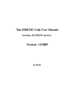
General
The FPGA – as a part of the F210 – represents an interface between a userselectable configuration of I/O modules (IP cores) and the PCI bus. The PCI core
included in the FPGA is a PCI target. It can be accessed via memory single/burst
read/write cycles.
The Wishbone bus is the uniform interface to the PCI bus. However, the FPGA may
have multiple internal buses, so that IP cores can be connected to one of several
internal buses, e.g., Wishbone or Avalon. This guarantees the highest possible
flexibility for different configurations of the FPGA.
Typically each implementation contains basic system functions such as reset and
interrupt control etc. and the system library, which are also IP cores.
Figure 6. FPGA – Block diagram (exemplary)
PCI bus
FPGA
PCI
Master
PCI
Slave
PCI‐to‐
Wishbone Bridge
IP Core
...
Wishbone
IP Core
...
Avalon
IP Core
...
IP Core
...
Config Table
Config Table
A configuration table provides the information which modules are implemented in
the current configuration. Furthermore the revision, the instance number (one
module can be instantiated more than one time), the interrupt routing and the base
address of the module are stored. At initialization time, the CPU has to read the
configuration table to get the information of the base addresses of the included
modules.
Note that with regard to the FPGA resources such as available logic elements or pins
it is not possible to grant all possible combinations of the FPGA IP cores. The
following chapter describes one possible configuration of the FPGA. Please ask our
sales staff for other configurations.
You can find an overview and descriptions of all available FPGA IP cores on MEN’s
website.
MEN Mikro Elektronik GmbH
20F210-00 E5 – 2013-04-26
32
FPGA
3.2
Standard Factory FPGA Configuration
The factory FPGA configuration for standard boards comprises the following FPGA
IP cores:
•
•
•
•
•
•
•
16Z024-01_Chameleon – Chameleon table
16Z014_PCI – PCI-to-Wishbone Bridge
16Z100_WBBUS – Wishbone Bus Interconnection Unit
16Z069_RST – Reset controller
16Z052_GIRQ – Interrupt controller
16Z045_FLASH – Flash controller
16Z057_UART – UART controller (2 IP cores, controls GSM-R, GPS and
UART serial interfaces)
- Quad UART 0 - Instance 1 is connected to the GPS interface
- Quad UART 0 - Instances 2 and 3 are connected to the GSM interface
- Quad UART 1 - Instance 1 is connected to SA-Adapter X1
- Quad UART 1 - Instance 2 is connected to SA-Adapter X2
MEN Mikro Elektronik GmbH
20F210-00 E5 – 2013-04-26
33
Appendix
4
Appendix
4.1
Literature and Web Resources
• F210 data sheet with up-to-date information and documentation:
www.men.de
4.1.1
CompactPCI
• CompactPCI Specification Revision 2.0 R3.0:
1997; PCI Industrial Computers Manufacturers Group (PICMG)
www.picmg.org
• PCI Local Bus Specification Revision 2.1:
1995; PCI Special Interest Group
P.O. Box 14070
Portland, OR 97214, USA
www.pcisig.com
4.1.2
GSM-R
• GSM-R modem:
Triorail TRM:2; data sheet; 2006; Triorail GmbH & Co. KG
www.triorail.com
• GSM-R in general:
http://en.wikipedia.org/wiki/GSM-R
• SIM cards in general:
http://en.wikipedia.org/wiki/Subscriber_Identity_Module
4.1.3
GPS
• GPS controller (board revision >= R01):
Navman Jupiter 30 GPS receiver module; data sheet; 2006; Navman New Zealand
www.navman.com
• GPS controller (board revision < R01):
HiSense HS110 Embedded GPS module; data sheet; 2004; CellGuide Ltd.
www.cell-guide.com
• GPS in general:
http://en.wikipedia.org/wiki/Gps
4.1.4
SA-Adapters
• MEN SA-Adapters:
www.men.de/products/search.asp?prodc=accessories.1&h=SA-Adapters
MEN Mikro Elektronik GmbH
20F210-00 E5 – 2013-04-26
34
Appendix
4.2
ID EEPROM
The F210 has an ID EEPROM containing factory information on the board. This
EEPROM is connected to the FPGA via SMBus. Although you normally should not
modify factory data, you may change the EEPROM information if needed.
The addresses are configured as follows:
• First 256 bytes: 0xAC
• Second 256 bytes: 0xAE
By standard the EEPROM contains the following data:
•
•
•
•
Product name: ’F210’
Model: e.g. ’00’
Revision: e.g. ’00.00.00’
Serial number: e.g. ’000023’
MEN offers an MDIS-based driver to modify EEPROM data. Please see MEN’s
website for downloads.
4.3
Finding out the Board’s Article Number, Revision and
Serial Number
MEN user documentation may describe several different models and/or hardware
revisions of the F210. You can find information on the article number, the board
revision and the serial number on two labels attached to the board.
• Article number: Gives the board’s family and model. This is also MEN’s ordering number. To be complete it must have 9 characters.
• Revision number: Gives the hardware revision of the board.
• Serial number: Unique identification assigned during production.
If you need support, you should communicate these numbers to MEN.
Figure 7. Labels giving the board’s article number, revision and serial number
Complete article number
02F210-00
01.00.00
Revision number
Serial number
MEN Mikro Elektronik GmbH
20F210-00 E5 – 2013-04-26
35