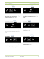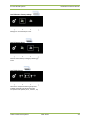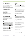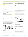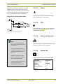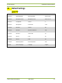
1
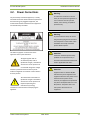
D-CERNO Wired Conference System Installation and User Manual D-Cerno Wired System Installation and User Manual Table of Contents Table of Contents ......................................................................................................................... 2 Section 1 – General Information ................................................................................................... 5 1. Copyright Statement...................................................................................................... 7 2. Trademarks ................................................................................................................... 8 3. Conformity info ............................................................................................................. 8 4. Safety Instructions ......................................................................................................... 8 4.1. 4.2. Important safety instructions ......................................................................................... 8 Power Connections .......................................................................................................11 5. D-Cerno System Information .........................................................................................12 5.1. 5.1.1. General System Architecture ........................................................................................12 Components .......................................................................................................................... 12 Section 2 – System Components ..................................................................................................13 6. Table Top Delegate units ..............................................................................................15 6.1. 6.2. 6.3. 6.4. 6.4.1. 6.4.2. Introduction .................................................................................................................15 Controls and indicators .................................................................................................15 Installation ...................................................................................................................16 Microphones ................................................................................................................17 Introduction ........................................................................................................................... 17 Electrical and acoustic properties ........................................................................................ 17 6.5. 6.6. 6.6.1. 6.6.2. Dimensions ..................................................................................................................17 Maintenance ................................................................................................................18 General .................................................................................................................................. 18 Cleaning ................................................................................................................................. 18 7. Central Control unit ......................................................................................................19 7.1. 7.2. 7.3. 7.3.1. Introduction .................................................................................................................19 Controls and indicators .................................................................................................19 External Connections ....................................................................................................19 Power Supply ......................................................................................................................... 20 Televic Conference Systems 2011-04-19 2 D-Cerno Wired System 8. Installation and User Manual System cables ...............................................................................................................20 Section 4 – System Configuration .................................................................................................21 9. Initialisation .................................................................................................................22 10. Configuration ...............................................................................................................22 10.1. Menu structure ............................................................................................................22 10.1.1. Overview: .............................................................................................................................. 22 10.1.2. Menu items ........................................................................................................................... 23 Section 4 – ..................................................................................................................................29 The Menu explained ....................................................................................................................29 11. Main Menu...................................................................................................................31 11.1. Config menu .................................................................................................................31 11.1.1. Volume .................................................................................................................................. 31 11.1.2. Headphone volume ............................................................................................................... 31 11.1.3. Conference modes ................................................................................................................ 31 11.1.4. Microphone Limit .................................................................................................................. 31 11.1.5. Microphone preset ................................................................................................................ 31 11.1.6. Audio out ............................................................................................................................... 31 11.1.7. Audio In ................................................................................................................................. 32 11.1.8. Independent aux settings ...................................................................................................... 32 11.1.9. N_1 (Remote Conferencing) .................................................................................................. 32 11.1.10. External Equalizer .................................................................................................................. 32 11.1.11. Chime..................................................................................................................................... 33 11.1.12. ECO ........................................................................................................................................ 33 11.1.13. Factory settings reset ............................................................................................................ 33 11.1.14. System info ............................................................................................................................ 33 Section 5 – Appendix ...................................................................................................................34 12. Default Settings juist??? ...............................................................................................35 Televic Conference Systems 2011-04-19 3 D-Cerno Wired System Installation and User Manual Draft History : Hoofdstuk bijgewerkt door alle DIV 04/04/2011 V3 Menu structuur update DIV 05/04/2011 V4 Correctie fouten in Aux DIV IN/out + aangevuld met uitleg N_1 en Ext. Eq. 05/04/2011 V4 System Cables naar Section 2 DIV 05/04/2011 V4 Maintenance zat er 2 x in DIV 05/04/2011 V4 Menu structuur wat verduidelijkt DIV 08/04/2011 V5 Conformity info toegevoegd DIV 14/04/2011 V6 Bitmaps gewijzigd DIV 19/04/2011 V7 Televic Conference Systems datum 2011-04-19 versie 4 D-Cerno Wired System Installation and User Manual Section 1 – General Information Televic Conference Systems 2011-04-19 5 D-Cerno Wired System 1. Installation and User Manual Copyright Statement No part of this publication or documentation accompanying this product may be reproduced in any form or by any means or used to make any derivative such as translation, transformation, or adaptation without the prior written permission of the publisher, except in case of brief quotations embodied in critical articles or reviews. Contents are subject to change without prior notice. Copyright© 2011 by Televic Conference NV. All rights reserved. The authors of this manual have made every effort in the preparation of this book to ensure the accuracy of the information. However, the information in this manual is supplied without warranty, either express or implied. Neither the authors, Televic Conference NV, nor its dealers or distributors will be held liable for any damages caused or alleged to be caused either directly or indirectly by this book. Televic Conference Systems 2011-04-19 7 D-Cerno Wired System 2. Installation and User Manual 1. Trademarks All terms mentioned in this manual that are known to be trademarks or service marks have been appropriately capitalized. Televic Conference NV cannot attest to the accuracy of this information. Use of a term in this book should not be regarded as affecting the validity of any trademark or service mark. Read Instructions All the safety and operating instructions should be read before the product is operated. 1. Retain Instructions The safety and operating instructions should be retained for future reference. 2. Heed Warnings All warnings on the product and the operating instructions should be adhered to. 3. Conformity info 3. All instructions for installation or operating / use should be followed. The D-Cerno Wired Conference system is compliant with following standards: 4. EN60065 EN55103-1/-2 IEC60914 Safety Instructions The D-Cerno Conference system is state of the art and has been designed to meet quality. Nevertheless, the individual components of the conference system can cause danger for persons and material assets if the conference system is not used as intended, the conference system is set up by personnel not familiar with the safety regulations, the conference system is converted or altered incorrectly, the safety instructions are not observed. Televic Conference Systems Ventilation Slots and openings in the cabinet are provided for ventilation and to ensure reliable operation of the product and to protect it from overheating. These openings must not be blocked or covered. The openings should never be blocked by placing the product on a bed, sofa, rug, or other similar surface. This product should not be placed in a built-in installation such as a bookcase or rack unless proper ventilation is provided or the manufacturer's instructions have been adhered to. 6. Heat The product should be situated away from heat sources such as radiators, heat registers, stoves, or other products (including amplifiers) that produce heat. 7. 4.1. Important safety instructions Cleaning Unplug this product from the wall outlet before cleaning. Do not use liquid cleaners or aerosol cleaners. Use a damp cloth for cleaning. 5. 4. Follow Instructions Attachments Do not use attachments not recommended by the product manufacturer as they may cause hazards. 8. 2011-04-19 Water and Moisture 8 D-Cerno Wired System Installation and User Manual Do not use this product near water or in a moistures environment - for example, near a bath tub, wash bowl, kitchen sink, or laundry tub; in a wet basement; or near a swimming pool, in an unprotected outdoor installation; and the like. 9. Accessories Only use attachments/accessories specified by the manufacturer. Do not place this product on an unstable cart, stand, tripod, bracket, or table. The product may fall, causing serious injury to a child or adult, and serious damage to the product. Use only with a cart, stand, tripod, bracket, or table recommended by the manufacturer, or sold with the product. Any mounting of the product should follow the manufacturer's instructions, and should use a mounting accessory recommended by the manufacturer. 10. Moving A product and cart combination should be moved with care. Quick stops, excessive force, and uneven surfaces may cause the product and cart combination to overturn. Do not defeat the safety purpose of the polarized or ground-type plug. A polarized plug has two blades with one wider than the other. A grounding type plug has two blades and a third grounding prong. The wider blade or the third prong are provided for your safety. If the provided plug does not fit into your outlet, consult an electrician for replacement of the obsolete outlet. 14. Power-Cord Protection Power-supply cords should be routed to that they are not likely to be walked on or pinched by items placed upon or against them, paying particular attention to cords at plug, convenience receptacles, and the point where they exit from the product. 15. Lightning For added protection for this product during a lightning storm, or when it is left unattended and unused for long periods of time, unplug it from the wall outlet. This will prevent damage to the product due to lightning and power-line surges. Not applicable when special functions are to be maintained, such as evacuation systems 11. Power Sources This product should be operated only from the type of power source indicated on the marking label. If you are not sure of the type of power supply to your home, consult your product dealer or local power company. For products intended to operate from battery power, or other sources, refer to the operating instructions. 12. Power Lines An outdoor system should not be located in the vicinity of overhead power lines or other electric light or power circuits, or where it can fall into such power lines or circuits. When installing an outdoor system, extreme care should be taken to keep from touching such power lines or circuits, as contact with them might be fatal. U.S.A. models only - refer to the National Electrical Code Article 820 regarding installation of CATV systems. 16. Overloading Do not overload wall outlets, extension cords or integral convenience receptacles as this can result in a risk of fire or electric shock. 17. Object and Liquid Entry Never push objects of any kind into this product through openings as they may touch dangerous voltage points or short-out parts that could result in a fire or electric shock. Never spill liquid of any kind on the product. 18. Inflammable and Explosive Substance Avoid using this product where there are gases, and also where there are inflammable and explosive substances in the immediate vicinity. 13. Grounding or Polarization Televic Conference Systems 2011-04-19 9 D-Cerno Wired System Installation and User Manual 19. Heavy Shock or Vibration substitutions may result in fire, electric shock, or other hazards. When carrying this product around, do not subject the product to heavy shock or vibration. 23. Safety Check 20. Servicing Upon completion of any service or repairs to this product, ask the service technician to perform safety checks to determine that the product is in proper operating condition. Do not attempt to service this product yourself as opening or removing covers may expose you to dangerous voltage or other hazards. Refer all servicing to qualified service personnel. 24. Coax Grounding 21. Damage Requiring Service Unplug this product from the wall outlet and refer servicing to qualified service personnel under the following conditions: a. When the power-supply cord or plug is damaged. b. if liquid has been spilled, or objects have fallen into the product. c. If the product has been exposed to rain or water. d. If the product does not operate normally by following the operating instructions. Adjust only those controls that are covered by the operating instructions as an improper adjustment of other controls may result in damage and will often require extensive work by a qualified technician to restore the product to its normal operation. e. If the product has been dropped or damaged in any way. f. When the product exhibits a distinct change in performance-this indicates a need for service. If an outside cable system is connected to the apparatus, be sure the cable system is grounded. U.S.A. models only: Section 810 of the National Electrical Code, ANSI/NFPA No.70-1981, provides information with respect to proper grounding of the mount and supporting structure, grounding of the coax to a discharge apparatus, size of grounding conductors, location of discharge unit, connection to grounding electrodes, and requirements for the grounding electrode. 22. Replacement Parts When replacement parts are required, be sure the service technician has used replacement parts specified by the manufacturer or have the same characteristics as the original part. Unauthorized Televic Conference Systems 2011-04-19 10 D-Cerno Wired System Installation and User Manual 4.2. Power Connections Warning: For permanently connected equipment, a readily accessible disconnect device shall be incorporated in the fixed wiring; For pluggable equipment, the socket-outlet shall be installed near the equipment and shall be easily accessible. To reduce the risk of fire or electric shock, do not expose this appliance to rain or moisture. Do not open the cabinet; refer servicing to qualified personnel only. Warning: To prevent electric shock, do not use this (polarized) plug with an extension cord receptacle or other outlet unless the blades can be fully inserted to prevent blade exposure. This label may appear on the bottom of the apparatus due to space limitations. Attention: Installation should be performed by qualified service personnel only in accordance with the National Electrical Code or applicable local codes. The lightning flash with an arrowhead symbol, with an equilateral triangle, is intended to alert the user to the presence of un-insulated ‘dangerous voltage’ within the products enclosure that may be of sufficient magnitude to constitute a risk of electric shock to persons. Attention: Equipment with or without ON/OFF switches have power supplied to the equipment whenever the power cord is inserted into the power source; however, the equipment is operational only when the ON/OFF switch is in the ON position. The power cord is the main power disconnect for all equipment. The exclamation mark within an equilateral triangle is intended to alert the user to the presence of important operating and maintenance (servicing) instructions in the literature accompanying the appliance. Televic Conference Systems 2011-04-19 11 D-Cerno Wired System 5. Installation and User Manual D-Cerno System Information 5.1. General System Architecture 5.1.1. Components Figure 5.1.1: D-Cerno Chairman Unit Central units D-Cerno CU : basic central unit for D-Cerno system D-Cerno CU-R : The D-Cerno CU-R is the exclusive central unit for the D-Cerno system and comes with an integrated USB recording module and web server. The D-Cerno CU(-R) is the heart of the system meant to control small to mid-sized meetings. It controls 50 delegate units and can be expanded up to 150 units by a master-slave configuration with multiple central units. (*) Control of the system is easy and intuitive via the touch sensor buttons and a large LCD menu. Next to this the D-Cerno CU-R offers also the possibility to control and configure the system via the integrated webserver and USB recordingmodule. The delegate units D-Cerno delegate units make use of touch sensor buttons . The system is designed to work out-of-the box, Wiring is easy, shielded Cat5 cables from unit to unit. While connecting there is no need to worry about the IN and OUT port as the unit detects the direction of the signal flow automatically. There is no initialization procedure required. After wiring the system, it is ready for operation. (*) not yet implemented At the front of the D-Cerno CU-R units there are two USB connections to connect a USB storage device for direct recording of the meeting. To guide the meeting several conference modes are implemented. Direct access, Request, Push to talk, FIFO and Vox control (*). Delegate units are connected in daisy chain over the 4 bus connections ( 4 branches or 2 closed loops). When cabled in loop, a patent pending redundancy mechanism garantees that the system continues to work, should a cable break or be disconnected for some reason. Televic Conference Systems 2011-04-19 12 D-Cerno Wired System Installation and User Manual Section 2 – System Components Televic Conference Systems 2011-04-19 13 D-Cerno Wired System 6. Installation and User Manual Table Top Delegate units 6.1. Introduction The delegate units consist out of Discussion and Chairman units. Both are used for speech reinforcement in a conference room. The chairman units are used to guide and control an ongoing discussion. 6.2. Controls and indicators The D-Cerno delegate units have the following features: 1. Microphone touch sensor button: Activation/deactivation of the microphone. Indication LEDs show the status of the microphone. (red : active, green : request) 2. Loudspeaker: Distributes the floor channel. Mutes in case microphone is active. 3. Headphone connectors: Connection of headphone to the wireless unit. Mono- and stereo headphones can be used. 4. Volume touch sensor buttons: Change the volume level of the headphones. 5. PRIOR button: (chairman unit only) permanently deactivates the microphone of all active units. 6. Ring Led Figure 6.2.1: D-Cerno Discussion Unit The ring led is illuminated when the microphone is on 7. NEXT button: (chairman unit only) Grants the floor to the next delegate in the waiting list. Televic Conference Systems 2011-04-19 15 D-Cerno Wired System Installation and User Manual 6.3. Installation D-Cerno units offer free input/output connectivity to allow flexible installation. The delegate units can be connected as a daisy chain branch or in loop to ensure redundancy Figure 6.3: D-Cerno connectivity Figure 6.2.2: D-Cerno Chairman Unit Televic Conference Systems 2011-04-19 16 D-Cerno Wired System Installation and User Manual 6.4. Microphones 6.5. Dimensions 6.4.1. Introduction Mechanische tekeningen voorzien (afmetingen)… The D-Cerno microphone has a uni-directional response for optimum performance even in noisy conditions, and has a very low susceptibility to RFinterference from mobile phones. 6.4.2. Electrical and acoustic properties Table 6.4.2: Microphone characteristics ???? Transducer type Back electret (condenser) ??? Operating principle Pressure gradient ??? Polar pattern Uni-directional, cardioid ??? Frequency response 130 Hz – 150000 Hz Nominal impedance 1kOhm (at 1 kHz, drop resistance = 1k2, Vdd = 3.3VDC ) Load impedance > 5kOhm ???? Max.SPL at 1 kHz 120 dB SPL ???? Equivalent sound pressure level < 25 dB(A) ???? Free field sensitivity 7mV/Pa, +/- 3 dB at 1 kHz or (-43dB, 0dB=1V/Pa at 1kHz) ???? Power supply 3.3V DC, 0.5 mA ???? Consumption 0.5 mA (without LED ring); ??? max. 25 mA (with illuminated ring) Televic Conference Systems 2011-04-19 17 D-Cerno Wired System Installation and User Manual 6.6. Maintenance 6.6.1. General Caution: Do not put any objects on top of the units. Object falling through the holes of the unit can cause damage. Caution: Do not install the units in a location near heat sources as radiators, air ducts. or direct sunlight. Caution: Make sure the units are not exposed to excessive dust, humidity, mechanical vibration or shock. 6.6.2. Cleaning Caution: Do not use alcohol, ammonia or petroleum solvents or abrasive cleaners to clean the units. To keep its original condition it is advised to periodically clean the unit: Use a clean soft cloth that is not fully moist. Make sure the device is completely dry before usage. Televic Conference Systems 2011-04-19 18 D-Cerno Wired System 7. Installation and User Manual 2. Central Control unit 4 x RJ45 ports to connect up to max 50 delegate units. (25 units per branch or loop) 7.1. Introduction The D-Cerno CU is the heart of the system. It controls all delegate units and can interconnect to other systems either via the external audio connections The system has a built in power supply to drive up to 50 units and can operate in a standalone mode. Initialization and configuration can be done via the integrated menu. Figure 7.3.2: system ports The green indicator points to detected signal , without errors (devices detected). The yellow indicator points to error or no signal .detected (no devices connected) 3. 2 x RJ45 ports Figure 7.3.3: Master – Slave ports Reserved for master – slave connection (not yet implemented) 4. LAN connector (D-Cerno CU-R only) Figure 6.1: D-Cerno connectivity Figure 7.3.4: LAN connector 7.2. Controls and indicators Webserver connection 5. Two unbalanced RCA audio output connectors to extract analog audio floor signal All controls are done via touch panel by means of an intuitive user interface menu (see chapter 6.4) A user can activate or select a control or menu item by touching one of the symbols beneath the display , with his finger , without the need to push. 7.3. External Connections 1. Figure 7.3.5: Aux Out The green indicators light up when there is an output signal present 6. +48V DC power connector Figure 7.3.1: DC power connector Televic Conference Systems One unbalanced RCA analog audio input connector to add external signal to the floor Figure 7.3.6: Aux Out 2011-04-19 19 D-Cerno Wired System Installation and User Manual The red indicators light up when there is an overload of the input signal occurring 7. 8. One balanced XLR analog audio connector to add external signal to the floor The system cables used as connection between the central unit and the contribution equipment, and from unit to unit is Cat5e AWG 24 FTP shielded cables with shielded RJ45 plugs. The red indicators light up when there is an overload of the input signal occurring The AUX In connections on the central unit have a XLR 3 Female connector. So a cable with XLR 3 Male connector should be used to insert an external signal. Figure 6.3.7: D-Cerno connectivity System cables Televic has standard pre-made cables available in different lengths: 2m 5m 10m 20m ICC5/2 ICC5/5 ICC5/10 ICC5/20 71.60.4002 71.60.4005 71.60.4010 71.60.4020 The voltage level at the output of the central unit is 48 V. Every meter of cable and conference unit in a branch causes a voltage drop. Every unit in a branch should receive at least 30V ??. Delegate units will automatically shut down if the supplied voltage is too low. Pin 1 Shield Pin 2 Signal + Pin 3 Signal - 8. Headphone connector Mono or stereo headphones with 3.5mm connector may be used Figure 7.3.8: Headphone connector 7.3.1. Power Supply The power supply can operate on an inputvoltage range of 100-240Vac , 47-63Hz. The output voltage is 48V dc – 3.15A max Televic Conference Systems 2011-04-19 20 D-Cerno Wired System Installation and User Manual Section 4 – System Configuration Televic Conference Systems 2011-04-19 21 D-Cerno Wired System 9. Installation and User Manual Initialisation All delegate units are initialised automatically as soon as they are connected . Delegate units may be connected or disconnected while the system is active. There is no SW limitation on the amount of delegates that can be initalised , however , due to the limitation of the internal power supply , correct functionality is only guaranteed up to 50 delegate units per CU. 2 level is adjustment settings within selected menu item 3 level is volume adjustments for Aux in/out nd rd Menu navigation symbols ↓ = acknowledge setting or go one level lower in the selected menu item ↑ = return one level higher in the menustructure 10. Configuration < = move left in the menu > = move right in the menu 10.1. Menu structure The menu structure on the next pages can be used as a quick reference guide to configure the conference systems. = config menu = selected item is highlighted by a frame around it 10.1.1. Overview: The menu structure consists out of 4 levels : Main menu Config menu Level 2 menu Level 3 menu Main menu and Config menu selection 1 level configuration menu is a ringstructure that allows to scroll through the different configuration menu items st Televic Conference Systems 2011-04-19 22 D-Cerno Wired System Installation and User Manual Main menu 10.1.2. Menu items Config menu Level 2 menu Config menu Volume Main menu Level 3 menu Config menu Level 2 menu Main menu Level 3 menu Start up of CU….. Adjusting volume of loudspeakers Main menu Config menu Level 2 menu Config menu Headphone Level 3 menu …….screen after startup Adjusting headphone volume Main menu Config menu Level 2 menu Select ↓ to enter the Configuration menu Config menu Conference mode Level 3 menu Main menu Config menu Level 2 menu Config menu System Info Level 3 menu Set conference mode Get System Info Televic Conference Systems 2011-04-19 23 D-Cerno Wired System Installation and User Manual Main menu Main menu Config menu Config menu Level 2 menu Config menu Max # Microphones Set allowed max number of microphones Main menu Config menu Level 2 menu Config menu Mic Preset Level 3 menu Level 2 menu Config Menu Audio In Level 3 menu Enter auxialiary input settings Config Menu N-1 / External Equalizer Main menu Config menu Level 3 menu Level 2 menu Level 3 menu Set microphone limiter gain setting Select N-1 or external equalizer mode Main menu Config menu Main menu Level 2 menu Config Menu Audio Out Config menu Level 3 menu Level 2 menu Config Menu Chime Level 3 menu Enter Auxialiary output settings Enter chime setting Televic Conference Systems 2011-04-19 24 D-Cerno Wired System Installation and User Manual Main menu Main menu Config menu Config menu Level 2 menu Config Menu ECO Level 2 menu Level 2 menu Volume setting Level 3 menu Enter energy saving settings Level 3 menu Use < > arrows to set speaker volume Main menu Config menu Level 2 menu Config menu Factory Settings Level 2 menu Headphone Volume setting Main menu Level 3 menu Config menu Level 2 menu Level 3 menu Enter factory settings selection Main menu Use < > arrows to set headphone volume Config menu Level 2 menu Config menu System Info Level 3 menu Level 2 Conference Mode (see also chapter 10.1.3 operating modes) Main menu Config menu Level 2 menu Level 3 menu Request mode Televic Conference Systems 2011-04-19 25 D-Cerno Wired System Installation and User Manual Main menu Level 2 Activation type : push to talk Config menu Main menu Level 2 menu Level 2 Conference Mode Config menu Level 3 menu Level 2 menu Level 3 menu FIFO/Override mode The delegate’s microphone is activated as long as the delegate keeps his finger on the mic symbol Main menu Config menu Level 2 menu Level 2 Conference Mode Level 3 menu Level 2 Activation type : VOX Direct Access mode In direct access mode , a selection out of 3 activation modes be chosen: Activation of delegate’s microphone by sound detection Main menu Config menu Level 2 Activation type : toggle microphone on/off Level 2 menu Level 2 Max microphone open Main menu Level 3 menu Config menu Level 2 menu Level 3 menu Max number of microphones allow on at the same Delegate can activate or de-activate his microphone time is visualized by number of between 1 and 8 : can be set by toggling on the mic symbol Televic Conference Systems 2011-04-19 26 D-Cerno Wired System Installation and User Manual Main menu Main menu Config menu Config menu Level 2 menu Level 2 menu Level 2 Audio Out Level 3 Audio In level Level 3 menu Select auxiliary output 1 or 2 settings via arrows and enter settings via ↓ arrow <> Set audio level of selected auxiliary input via < > arrows Main menu Main menu Config menu Config menu Level 2 menu Level 2 menu Level 3 Audio Out Level Level 3 menu Set audio level of selected auxiliary output via < > arrows Level 2 Chime Level 3 menu Select chime on or off Main menu Main menu Config menu Config menu Level 2 menu Level 2 Audio In Level 3 menu Level 3 menu Level 2 menu Level 2 ECO function Level 3 menu Switch ECO setting on or off Select auxialiary audio input 1 or 2 settings via < > arrows and enter settings via ↓ arrow Televic Conference Systems 2011-04-19 27 D-Cerno Wired System Installation and User Manual Main menu Config menu Level 2 menu Level 2 Restore Factory settings Level 3 menu Settings are as selected by the user Main menu Config menu Level 2 menu Level 2 Factory Reset Level 3 menu Confirm restore factory settings by selecting ↓ arrow Main menu Config menu Level 2 menu Level 2 Mic Preset Level 3 menu There are 3 microphone limiter gain presets available, depending of distance between microphone and speaker (close , medium , far) Televic Conference Systems 2011-04-19 28 D-Cerno Wired System Installation and User Manual Section 4 – The Menu explained Televic Conference Systems 2011-04-19 29 D-Cerno Wired System Installation and User Manual Direct Access 11. Main Menu Enables the participant to turn on his microphone at Config menu selection allows entering the different settings as described below any time , via the MIC icon . The only limitation here is the maximum number of microphones which are allowed may be active simultaneously. All selected settings are activated and immediately excepted for “restore factory settings” FIFO (1-8) : 11.1. Config menu Enables 1 to 8 microphone (depending on max # mic setting - see 10.1.4) at a time to be active without intervention of the conference chairman. Activation of a new microphone overrides the longest active microphone. 11.1.1. Volume Set volume of speakers 11.1.4. Microphone Limit 11.1.2. Headphone volume Set volume of headphone of the CU The maximum open microphones at the same time can be chosen between 1 and 8 . The same amount of chairman units can be activated on top of that , so max 16 microphones can be active at the same time . 11.1.3. Conference modes General : chairman microphones can always be activated , regardless chosen operating mode 11.1.5. Microphone preset Operating modes With request Enables the participant to activate or deactivate a request to have the floor by activating the MIC icon . The request is shown by a green illumination lightbar of the delegate unit. The microphone of the delegate unit that is in request can be activated by the chairman via the NEXT icon . The lightbar of delegate unit will then be illuminated in red. The chairman can cancel all the active microphones by activating the PRIOR icon . The chairman can cancel all requests by simultaneously activating the PRIOR and NEXT function. The request list can take max 64 requests There are 3 limiter gain presets to choose from. The choise between these 3 will depend on the general distance between the speaker and the microphone . This setting influences the sensitivity and the dynamic range of the microphones. There is also a fixed automatic gain reduction setting that reduces the volume per active microphone depending on the total number of active microphones. 11.1.6. Audio out The D-Cerno CU has 2 auxiliary output RCA connectors , labeled Televic Conference Systems 2011-04-19 and . 31 D-Cerno Wired System Installation and User Manual The level of the output signal is adjustable between …?????……. 11.1.9. N_1 (Remote Conferencing) Figure 1011.1.9.1: Aux N_1 Remote conferencing option gives the possibility to connect a central unit to e.g. a video conferencing system or telephone coupler. To prevent echoing the remote conferencing option needs to be set. 11.1.7. Audio In The central unit has two auxiliary inputs , one RCA connector , labeled and 1 XLR connector Connecting both central units to each other the AUX OUT 1 of one room needs to be connected with the AUX IN 1 of the other room and vice-versa. In both central units the remote conferencing option needs to be activated. labeled The input level is adjustable between …?????.... Audio path for N_1 11.1.8. Independent aux settings ≤8 ∑ Status RMS detector ∑ Std. ON Figure 1011.1.8.1: Independant Aux 1 Status Auxiliary input and output settings are independent form each other and allow external signal to be added to the floor and to extract the total floor signal Signal present Std. ON 1 Audio path for Independent Aux settings Figure 1011.1.9.2: Aux N_1 path ≤8 Σ : Status RMS detector Σ . : .. Std. ON 11.1.10. External Equalizer Status Signal present . Std. ON Figure 1011.1.10.1: Aux Ext Eq Figure 1011.1.8.2: Independent Aux path Televic Conference Systems To avoid feedback or to equalize audio signals it is possible to connect external equipment to the central unit. When this setting is chosen ,the floor signal will be disrupted in a way that all inputs signals 2011-04-19 32 D-Cerno Wired System Installation and User Manual will be directly routed to the AUX OUT . The signal present on AUX IN will be used as the new floor channel. This way it is possible to use external audio equipment like equalizers and feedback destroyers. The schematic below summarizes this feature. Chime When chime is activated , each use of the PRIOR button is followed by a chime sound Audio path for external equalizer Mode ≤ 8 11.1.11. Σ 11.1.12. Status RMS detector Σ Std. ON Σ .. 1 ECO External processing unit Status Signal present . Std. ON 1 When ECO function is set ON , the CU switches off automatically if during 1 hour ?? no activity and audio signal was detected. Figure 1011.1.10.2: Aux Ext Eq path 11.1.13. Factory settings reset Note: “N_1” and “External Equalizer” audio paths apply only to Aux In 1 and Aux Out 1. When this setting is selected and confirmed , factory settings are restored and CU is rebooted In N_1 setup mode, Aux Out 1 is considered as “local floor” out and Aux Out 2 is considered as “total floor” out. 11.1.14. Aux Input 1 is used as “Far End input” , so this signal will not be part of the Aux Out 1 signal. Displays system info as shown in example below Type number Software version Serial nr° Active ports # units configured Errors Aux Input 2 (XLR) is used to add a signal (e.g. from external microphones) to the local floor Televic Conference Systems System info 2011-04-19 D-Cerno CU v 1.01 10552685 1,3 21 None 33 D-Cerno Wired System Installation and User Manual Section 5 – Appendix Televic Conference Systems 2011-04-19 34 D-Cerno System Installation and User Manual 12. Default Settings juist??? Main Menu Item Sub Menu Item Item Default Value Conference Operating Mode Operating Mode Direct Access Conference Microphone Limit Microphone Limit Max. Limit = 4 Conference Loudspeaker Volume 6 Conference Microphones Limiter Gain 0 dB Aux-In/Out Aux Out 1 Volume 18 Aux-In/Out Aux Out 1 Remote Conference OFF Aux-In/Out Aux Out 2 Volume XLR 24 Aux-In/Out Aux In 2 Level 18 Aux-In/Out Aux In 2 Level 18 Aux-In/Out External Equalizer External Equalizer OFF Language Choose Language Language English Televic Conference Systems 2011-04-19 35 D-Cerno System Televic Conference Systems Installation and User Manual 2011-04-19 36