1
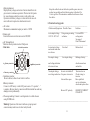
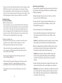
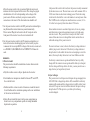
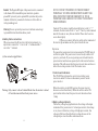
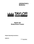
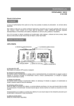
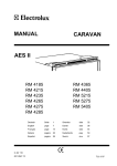
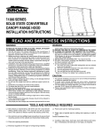
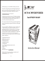
AIMS Operating Corp., Inc. dba AIMS Power Warranty Instructions:
This product is designed using the most modern digital technology and
under very strict quality control and testing guide lines. If however you
feel this product is not performing as it should, please contact us:
[email protected] or (775)359-6703
We will do our best to resolve your concerns. If the product needs repair
or replacement, make sure to keep your receipt/invoice, as that will need
to be sent back along with the package and RA# prepaid to AIMS. You
have a full 1 year from date of purchase warranty.
DC TO AC POW ER INV ERTER
Part# PWRINV500048W
This warranty is valid world wide with the exception that freight and duty
charges incurred outside the contiguous 48 United States will be prepaid
by customer.
Except as provided above, AIMS makes no warranty of any kind, express
or implied, including without limitation the implied warranties of
merchantability and fitness for a particular purpose. In no event shall
AIMS be liable for indirect, special or consequential damages. This
warranty only applies to AIMS Power branded products. All other name
brand products are warranted by and according to their respective
manufacturer. Please do not attempt to return non-AIMS Power branded
products to AIMS Power.
For additional products such as:
-Modified sine wave inverters
-Pure sine wave inverters
-Low Frequency Inverters
-Solar Charge Controllers
- On Grid Inverters
-Inverter Chargers and Automatic transfer switches
-Custom cut cables
-Batteries
-Solar Panels
Please visit our web site: www.aimscorp.net
To find out where to buy any of our products, you may also e-mail:
[email protected] or call (775)359-6703.
14
BAT TE R
Y
ON
Ove r Tem p
OFF
Ove r L oa d
15
14
13
12
11
10
600
480
360
240
120
Instruction Manual
SPECIFICATIONS
Model No
Maximum Continuous Output Power
Output Surge Capacity
PWRINV500048W
5000W
10000W
Modified Sine Wave
phase corrected
Output Wave Form
No Load Current DrawSwitch ON,
Switch OFF,
Efficiency
Input Voltage Range
Low Voltage Alarm
Low Voltage Shutdown
Over Temperature protection
<0,3 ADC
<0.2 mADC
90%
40-60V
DC 42 V+- 2V
DC 40 V+- 2V
55 c +- 5 c
570x210x180mm
or 22.44"x8.26"x7.08"
11KGS or 242
. LBS
Dimensions (L x W x H)
Weight
AC Output voltage : 120V
AC Output receptacles :
Output frequency : 60Hz
13
No output voltage,
voltage indicator
in upper red zone.
High input voltage
Make sure that
inverter
is connected to
48V battery.
Check regulation of
charging system.
________________________________________________________
Low battery alarm
Poor DC wirng, poor
Use proper cable
on all the time,
battery condition.
and make Solid
voltage indicator
connections. Use
below 44V
new battery
________________________________________________________
No output voltage,
Thermal shutdown
Allow inverter to
Over Heat indicator
cool off.Reduce
on,load in excess
load if continuous
5000W:125A(48V)
operation required.
________________________________________________________
No output voltage,
Thermal shutdown
Improve ventilation,
Over Heat indicator
make sure ventilation
on, load less than:
openings in inverter
5000W:125A(48V)
are not obstructed,
reduce ambient
temperature.
________________________________________________________
No output voltage,
Sort circuit or
Check AC wiring
Over Load indicator
Wiring error:
For short circuit or
on.
improper polarity
(active and neutral
reversed)
Very high power load Romove load
________________________________________________________
Maintenance
Very little maintenance is required to keep your inverter operating
properly. You should clean the exterior of the unit periodically
with a damp cloth to prevent accumulation of dust and dirt. At
the same time, tighten the screws on the DC input terminals.
12
Introduction
AIMS Power inverter series are the most advanced line of mobile
AC power systems available.
This model is used in a wide range of applications including
remote homes, RV's, sail boats and power boats. It will operate
most televisions and VTR's, personal computers, small appliances
and tools such as drills, sanders, grinders, mixers and blenders.
To get the most out of the power inverter, it must be installed
and used properly. please read the instructions in this manual
before installing and using this model.
Name and main function
1. Front view
d.BAR GRAPH METERS
b.OVER TEMPERATURE INDICATOR
BATTERY
15 600
14 480
13
360
12
11 240
10 120
Note:1.Only connect to "AC Terminal block" when the
Main Power ON/OFF switch is OFF.
2.lnverter's full power is avail able through
the AC Terminal Block.
ON
a.ON/OFF SWITCH
OFF
c.OVER LOAD INDICATOR
Over Temp
Over Load
AC Terminal Block
per outlet
MAX. 1500W
e.AC OUTLET
Live
Neutral
Ear th
g.AC TERMINAL BLOCK
Remote
a.ON/OFF switch:
Leave in the OFF position during installation.
f.REMOTE PORT
b.Over Temperature indicator:
Lights when inverter protects itself against overheating.Inverter
shuts down while indicator is on. Inverter will restart automatically
and indicator will trun off when the inverter cools.
c.Overload indicator:
Lights when inverter shuts down because of overload. Indicator will
turn off and inverter will restart when overload is removed.
1
d.Bar graph meters:
Display battery voltage and current. Current should be in the
green zone for continuous operation. The inverter will operate
for several minutes when the current is in the yellow zone.
Operation with battery voltage or current in the red zone of a
meter will result in protective shutdown of inverter.
e.AC outlets:
Maximum recommended output per outlet is 1500W
f.Remote port:
Used with remote switch to turn inverter ON/OFF.
g.AC Terminal block:
Hard wire block provides inverter's Full power.
2.Rear view
a.Ventilation window
DC input
X
b. Battery terminals
+
b. Battery terminals
c.Chassis grounding
a.Ventilation window:
Do not obstruct, allow at least l inch for air flow.
b.Battery terminals:
Connect to 48V battery or other 48V power source."+"is positive," - "
is negative, Reverse polarity connection will blow internal fuse and may
damage inverter permanently.
c.Chassis ground lug: Connect to earth ground or to vehicle chassis
using #8 AWG wire.
-Keep the cables between the battery and the power inverter
as short as possible and twist them togerter with about 2 to
3 twists per foot. This minimizes radiated interference from
the cables.
2.Troubleshooting guide
______________________________________________________
Problem and Symptoms Possible Cause
Solution
_______________________________________________________
Low output voltage
Using average reading Use trus RMS
110V:95-105V AC
voltmeter
reding meter
See page 4
Point 8 of manual
________________________________________________________
Low output voltage
Overload
Reduce load
and current indicator
in red zone.
_________________________________________________________
No output voltage
Low input voltage
Recharge battery.
and voltage indicator
in lower red zone
check connections
and cables
No output voltage,
Inverter switched off
no voltage indication No power to inverter
Turn inverter on.
Check wiring to
inverter
Have qualified
service technician
check and replace fuse.
Internal fuse open
Reverse DC polarity
________________________________________________________
Warning! Operation of the inverter without a proper ground
connection may result in an electrical safety hazard.
2
OBSERVE CORRECT
POLARITY.
11
The power inverter will also shut down if the input voltage exceeds
60V. This protects the inverter against excessive input voltage.
The voltage indicator will be in the upper red zone. Although the
power inverter incorporates protection against overvoltage, it may
still be damaged if the input voltage is allowed to exceed 60V.
Trorbleshooting
1.Common problems
a.Buzz in audio systems:
Some inexpensive stereo systems and "boom boxes"will emit a
buzzing noise from their loudspeakers when operated from the
power inverter. This is because the power supply in the device
does not adequately filter the modified sine wave produced by
the power inverter. The only solution is to use a sound system
that incorporates a higher quality power supply.
b.Television interference:
Operation of the power inverter can interfere with television
reception on some channels. If this situation occurs, the
following steps may help to alleviate the problem.
-Make sure that the chassis ground lug on the back of the
power inverter is solidly connected to the ground system of
your vehicle, boat or home.
-Do not operate high power loads with the power inverter
while watching television.
-Make sure that the antenna feeding your television provides
an adequate ("snow free") signal and that you are using
good quality cable between the antenna and the television.
-Move the television as far away from the power inverter as
possible.
10
Quick hook-up and testing
If you would like to quickly hook-up the power inverter and check
its performance before going ahead with your installation, please
follow these guidelines:
1.Unpack and inspect the power inverter, check to see that the
power switch is in the OFF position.
2.Connect the cables to the power input terminals on the rear
panel of power inverter.The red terminal is positive(+)and
black terminal is negative(-).
3.Connect Earth per section 3. Grounding on Page 5.
Connect the cable from the negative terminal of the inverter
to the negative terminal of the power source. Make a secure
connection.
Caution!Loosely tightened connectors rsesult in excessive voltage
drop and may cause overheated wires and melted insulation.
4.Before proceeding further,carefully check that the cable you have
just connected connects from the negative terminal of inverter
to the negative output terminal of the power source.
Caution!Reverse polarity connection will blow a fuse in the
inverter and may permanently damage the inverter.Damage
caused by reverse polarity connection is not covered by our
warranty.
5.Connect the cable from the positive terminal of the inverter to the
positive terminal of the power source. Make secure connection.
Warning!You may observe a spark when you make this connection
since current may flow to charge capacitors in the power inverter.
Do not make this connection in the presence of flammable fumes,
as explosion or fire may result.
3
6.Turn the power switch to the on position.Check the meters and
indicators on the front panel of the inverter. The voltage bar graph
should indicate 40 to 60 volts depending on the voltage of the
power source.If it does not,check your power source and the
connections to the inverter. The other indicators should be off.
7.Set the power inverter switch to the OFF position, the indicator lights
may blink and the internal alarm may sound momentarily.
This is normal. Plug the test load into the AC receptacle on the
front panel of the inverter. Leave the test load switch off.
8.Set the power inverter switch to the ON position and turn the test
load on, the inverter should supply power to the load. If you plan
to measure the true output R.M.S. voltage of the inverter, a meter such
as a FLUKE 87A, BACKMAN 4410 or TRIPLETT 4200 must be
used.
Installation
1.Where to install
The power inverter should be installed in a location that meets the
following requirements:
a:Dry-Do not allow water to drip or splash onto the inverter.
b.Cool-Ambient air temperature should be between 0 C and 40 C ,
the cooler the better.
c.Ventilation-Allow at least one inch of clearance around the inverter
for air flow.Ensure the ventilation openings on the rear and bottom
of the unit are not obstructed.
(the power delivered to the food) not the power actually consumed
by the microwave oven. The microwave oven will consume 40% to
100% more than its advertised cooking power. Check the rating
sticker on the back of the oven to determine its actual power draw.
The 5000W inverter will operate small microwave ovens (0.2 to
0.3 cubic foot capacity) that draw about 1700 watts.
Some induction motors used in refrigerators, freezers, pumps,
and other motor operated equipment require very high surge
currents to start. The power inverter may not be able to start
some of these motors even though their rated current draw is
within the rating of the power inverter.
If a motor refuses to start, observe the battery voltage indicator
while trying to start the motor. If the battery voltage indicator
drops below 44 volts while the inverter is attempting to start the
motor, this may be why the motor won't start. Make sure that
the battery connections are good and that the battery is fully
charged. If the connections are good and the battery is charged,
but the voltage still drops below 44 volts, you may need to use a
larger battery or larger battery bank.
2.Input voltage
The power inverter will operate with input voltage ranging from
40V-60V. If the voltage drops below 40V, an audible low battery
warning will sound and the voltage indicator will be in the lower
red zone. The power inverter will shut down if the input voltage
drops below 42V. This protects your battery from being
overdischarged.
d.Safety-Do not install the inverter in the same compartment as
batteries or in any compartment capable of storing flammable
liquids such as gasoline.
4
9
Ideally, the voltage should remain in the green area of the bar
graph. If the voltage goes into the red area at the top or bottom of
the graph, the inverter may shut-down.
3.Battery current indicator
The battery current bar graph indicates the current drawn from
the battery by the power inverter, It will not indicate current by
other loads also connected to the battery.
For long term operation, the current should be in the green area
of the bar graph. Short term operation is possible with current
in the orange area. If the current rises to the red area, the inverter
will reduce its output voltage to protect itself.
4.Overtemp indicator
The overtemp indicator indicates that the power inverter has shut
itself down because it has become overheated. The power
inverter may overheat because it has been operated at power
levels above its rating, or because it has been installed in
a location which does not allow it to dissipate heat properly.
5.Overlad indicator
The overload indicator indicates that the power inverter has
shut itself down because its output circuit has been short
circuited or drastically overloaded. Switch the ON/OFF switch
to OFF, correct the fault condition, and then switch the ON/OFF
switch back to ON.
Operating limits
1.Power output
The 5000W inverter will operate most AC loads within its power
rating. When determining whether a microwave oven can be
operated by the 5000W inverter, remember that the power
commonly advertised for microwave ovens is the cooking power
8
2.Cables:
DC to AC inverters require high amperage/low voltage DC power to
low amperage/high voltage AC power. To operate properly.connect
inverter DC input terminals directly to the battery with the heaviest wire
available. See chart below:
1 x set 4 Awg
3.Grounding
The power inverter has a lug on the rear panel marked "chassis ground"
This is to connect the chassis of the power inverter to the ground. The
ground terminals in the AC oulets on the front panel of the inverter are
also connected to the ground lug.
The chassis ground lug must be connected to a grounding
point,which will vary depending on where the power inverter is
installed.In a vehicle, connect the chassis ground to the chassis
of the vehicle.In a boat, connect to the boat's grounding systems.
In a fixed location,connect the chassis ground lug to an earth
point,which will vary depending on where the power inverter is
installed.
The neutral (common)conductor of the power inverter AC output
circuit is connected to the chassis ground.Therefore,when the
chassis is connected to ground,the neutral conductor will also be
grounded.This conforms to national electrical code requirements
that separately derived AC sources (such as inverters and generators)
have their neutral tied to ground in the same way that the neutral
conductor from the the utility line is tied to ground at the AC breaker
panel
5
Caution! The Negative DC input of the power inverter is connected
to the chassis. DO not install the power inverter in a positive
ground DC system. A positive ground DC system has the positive.
terminal of the battery connected to the chassis of the vehiclc or
to the grounding point.
Warning! Do not operate the power inverter without connecting it
to ground.Electrical shock hazard may result.
4.Battery Cable connections
When you connect the AC inverter to the battery terminals, it is
important to connect the "+" wire to the "+" terminal and the "-"
wire to the "-" terminal.
(a) See connection graph below:
RED
BLACK
Warnıng:Only connect to the ac Terminal Block when the inverter is turned
off and disconnected from the dc power source.
IF YOU CONNECT THE WIRES TO THE INCORRECT
TERMINALS. YOU WILL REVERSE THE POLARITY AND
WILL INSTANTLY VOID THE WARRANTY OF YOUR
INVERTER, SO BE CAREFUL TO CONNECT YOUR INPUT
WIRES PROPERLY.
Caution!1.To avoid any touch between the battery cords "+" "-"
terminals, the directions of both "+" and "-" battery cords terminals
must be the same or away from each other. Please also be sure to
secure them tightly.
2.When you connect the battery cables to the terminals of
the inverter, please make sure they do not touch the case.
Operation
To operate the power inverter,turn it on using the ON/OFF switch
on the front panel. The power inverter is now ready to deliver AC
power to your loads. If you are operating several loads from the
power inverter,turn them on separately after the inverter has been
turned on. This will ensure that the power inverter does not have to
deliver the starting currents for all the loads at once.
1.Controls and indicators
The ON/OFF switch turns the control circuit in the power
inverter on and off. It does not disconnect power from the
power inverter.
When the switch is in the OFF position, the power inverter
draws no current from battery. When the switch is in the ON
position but with no load, the power inverter draws less than
1 Amp.
2.Battery voltage indicator
The battery voltage bar graph indicates the voltage at the input
terminals of the power inverter. At low input current, this voltage
is very close to the battery voltage. At high input current, this
voltage will be lower than the battery voltage because of the
voltage drop across the cables and connections.
6
7