1
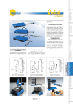
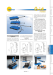
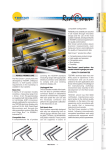
INSTRUCTION MANUAL
1.
INTRODUCTION TO DIGICROWN PROBING LINE SYSTEM ......... 4
2.
APPLICATION NOTES (232 UNIT) ................................................... 6
3.
APPLICATION NOTES (USB UNIT).................................................. 8
4.
LED FOR DISPLAY OF UNIT OPERATING STATUS .................... 10
4.1.
4.2.
“ON ERROR” OR “AUTOMATIC” MODE ...................................... 11
“AUTOMATIC” MODE .................................................................. 11
5.
GROUND CONNECTION................................................................. 12
6.
TECHNICAL SPECIFICATIONS ...................................................... 15
6.1.
6.2.
6.3.
DIGICROWN 232........................................................................... 15
DIGICROWN USB ........................................................................... 16
RS-232 CONNECTOR PIN-OUT (9-WAY D-SUB) .............................. 17
7.
INSTALLATION DIAGRAMS ........................................................... 18
8.
DECLARATION OF CONFORMITY................................................. 20
9.
ORDERING CODES ......................................................................... 21
NOTE .......................................................................................................... 23
-2-
-3-
1. INTRODUCTION TO DIGICROWN PROBING LINE SYSTEM
The DigiCrown is a flexible measuring system (from 1 to 372 sensors), configured in
networks (from 1 to 12) that can be connected to a PC via an RS232/USB interface or
dedicated RS485 interface cards for PCI or ISA bus.
The diagram below shows the elements of the DigiCrown system in their possible
configurations. This user manual follows up the installation of the DigiCrown 232/USB
unit.
-4-
-5-
2. APPLICATION NOTES ((232
232 UNIT)
The typical application of the 232 module is the interfacing of the DigiCrown NET with
a PC equipped with an RS-232 standard serial port (Fig. 1).
The 232 module requires to be matched with a PSU unit for the NET power supply.
The 232 module embeds a 2m cable with a 9-way sub D-type female connector. By
means of this cable is possible to connect the unit straight in a PC RS-232 serial port.
Fig. 1
-6-
The 232 module is fitted on the DigiCrown bus unit, by means of which the
communication with the data acquisition system takes place. The 232 module
supplies to the bus connector a square wave with a 75 KHz frequency, for the
generation of the sine wave that synchronizes the transducers. The connection to
the bus module is made via a 9-way sub D-type connector, which also supplies
power to the 232 module.
Within the CPU integrated in the module, there is an EEPROM memory for the
management of the retentive-type data.
Each 232 module, moreover, contains a LED for a quick diagnosis of the operating
status of the unit (see Chapter 3).
MICROPROCESSOR
Synchr. Gen.
-7-
3. APPLICATION NOTES ((USB
USB UNIT)
The DigiCrown USB is now available in
two configurations
-
USB full speed
-
USB high speed
The USB full speed works with PC USB
version V1.1 mistead the latest high
speed works with PC USB version V2.0
Installing QSPC, Easy Acquisition or the
Marposs Driver Library, will allow the
automatic detection of the USB unit as
soon as it’s plugged to the host PC. As
soon as Windows finds the new
hardware connected, select the option
“Install the software automatically” and
click on “Next” (fig. 2). The driver for the
USB unit will then be installed.
The software configuration of the USB
module (using the MDHQSPC driver) is
done in the same manner as for the 232
unit.
Using the wizard it is possible to identify automatically the available COM port to be
plugged and to be used for the communication during the net configuration.
Fig. 2
-8-
The USB module requires to be matched with a PSU unit for the NET power supply
(see figure 3).
Fig. 3
-9-
4. LED FOR DISPLAY OF UNIT OPERATING STATUS
The type of lighting of the red LED on the 232/USB module indicates the operating
status of the unit. There are the following flashing modes:
•
“ON ERROR” (the LED is activated only when an error is generated).
•
“AUTOMATIC" (this mode includes both the ON ERROR warning and brief
flashes to indicate the network sessions pending – par. 3.2).
- 10 -
4.1. “ON ERROR” or “AUTOMATIC” mode
HW error
(1)
Notes:
(1) HW ERROR Æ general hardware and bootstrap errors
(2) COM ERROR Æ general serial driver and/or protocol error
4.2. “AUTOMATIC” mode
Notes:
(3) OK Æ the network is in working order
- 11 -
5. GROUND CONNECTION
In this chapter are reported different technical solutions in order to make sure the
DigiCrown system is properly grounded, according to the NET’s configuration and to
the lay-out of the different units.
The purpose of ground connection is to minimize as much as possible the
electrical noise and the interference, typically affecting the measurement
signal.
The ground connections schemes reported in this paragraph represent the optimal
solution in order to have a system fully compatible with the EMC standards,
according to the following directives:
-
73/23/EEC
2004/108/CE
EN55022: 1998 (EMC)
EN55024: 1998 (EMC)
If for a specific application the customer considers such technical solutions not
required, Marposs is not responsible for any possible inaccurate working condition
of the devices.
•
Bench application n. 1
The whole DigiCrown system (control + measurement) has been placed on a
single bench gauge.
PC
serial link
D
box
A
p.e.
The “D” equipotential connection between the box modules and the
transducers support frame, can be done whether a metallic conductive frame
is used. In the glass gauging applications the transducers support frame is
usually not a conductive material and the transducers are typically insulated, in
this case no ground connection is required.
- 12 -
•
Bench application n. 2
In case the control system (PC…) is placed on a bench while the transducers
and the box modules on another, we suggest to set-up an equipotential link as
shown in the points: A + D + E.
Power
supply
unit
PC
serial link
D
A
E
A.C.
Main
power
p.e.
•
Bench application n. 3
If the DigiCrown system is split on two or more benches, we suggest to set-up
an equipotential link as shown in the points: A + D + E + F + G.
Power
supply
unit
Power
supply
unit
Pc
serial link
box
serial link
A
E
D
p.e.
box
G
F
A.C.
Main
power
A.C.
Main
power
- 13 -
•
Automatic machine application
For such applications it is strongly suggested to provide the box units and the
transducers support frame with an equipotential link: in the automatic machine
applications the eddy-currents normally flow in the transducer’s shield.
Electrical cabinet
Pc
Measuring machine
box
serial link
pe
Ground bar
Ground bar
Equipotential
link
- 14 -
Metallic connection
between the modules
and the transducers
6. TECHNICAL SPECIFICATIONS
6.1. DigiCrown 232
DigiCrown 232
Communication
1 RS232 full-duplex channel no “handshake”
(RTS/CTS), or alternatively “hardware handshake”
- baud: 4800/ 9600 (default)/ 19200/ 38400/ 57600/
115200 bit/sec
Port setting
- bit number 8
- bit stop number 1
- parity EVEN
Bus interface
serial interface RS485 Half-Duplex
Power absorption
40mA
Operating temperature
0 ÷ 60°C
Storing temperature
-20 ÷ +70°C
Protection degree
IP 43
Power supply
+7.5Vdc (-20% +30%)
Input
RS232 9-way sub D-type female connector
Dimensions
see Chapter 7
- 15 -
6.2. DigiCrown usb
Usb full speed
1 virtual COM channel with USB interface
Communication
(compatible with USB 1.1 / 2.0 standards)
- to activate the full speed
program a baud higher
than 9600 bit/sec (19200 /
38400 / 57600 / 115200
bit/sec)
Port setting
- bit number 8
- bit stop number 1
- parity EVEN
Bus interface
Power absorption
bus 485
Usb high speed
Any programmed baud
active the maximum USB
speed:
- 12Mbit/s if connected to
a full speed port
- 480Mbit/s if connected to
a high speed port
serial interface RS485 Half-Duplex
from
40 mA
90 mA
Power absorption from usb
26 mA
Any absorption from the usb
Operating temperature
0 ÷ 60°C
Storing temperature
-20 ÷ +70°C
Protection degree
IP 43
Power supply
+7.5Vdc (-20% +30%)
Input
Type “A” USB connector
Dimensions
see Chapter 7
- 16 -
6.3. RS-232 connector pin-out (9-Way D-Sub)
1 = NC
2 = TX
3 = RX
4 = NC
5 = GND
6 = NC
7 = CTS
8 = RTS
9 = NC
- 17 -
7. INSTALLATION DIAGRAMS
232 and USB modules
Fastening
tongue
Bus module
Locking device
- 18 -
Hooking of 232 and USB module to bus connector
Dimensions of fastening to stand
- 19 -
8. DECLARATION OF CONFORMITY
MARPOSS S.p.A. hereby declares that the devices described in this manual comply
to the
safety requirements and EMC electromagnetic compatibility requirements,
in compliance with the following directives:
73/23/EEC
of 02-19-1973
(LOW VOLTAGE directive)
2004/108/CE
of 01-20-2005
(EMC directive)
The devices have been designed, assembled and tested in compliance with the
following European standards:
EN60950
: 2000
(Safety)
EN61326 - 1 : 1997
(EMC)
EN61326/A1 : 1998
(EMC)
- 20 -
9. ORDERING CODES
The tables below are a general summary of the ordering codes for all the
components of the DigiCrown Probing Line.
INTERFACES
DESCRIPTION
ORDER CODE
DIGI CROWN BOX
767X000100
DIGI CROWN BOX + RAM
767X000210
DIGI CROWN BOX 2 TRANSDUCERS
767X200400
DIGI CROWN 232
767Y000100
DIGI CROWN USB HIGH SPEED
767Y010400
DIGI CROWN PSU
(110-240VAC/7,5VDC)
DIGI CROWN PSU
767W000000
767W010000
(24VDC/7,5VDC)
DIGI CROWN AI
767A000400
DIGI CROWN EI
767E010400
DIGI CROWN I/O SINK
767I000400
DIGI CROWN I/O SOURCE
767I010400
DIGI CROWN I/O ONLY INPUT
767I020400
DIGI CROWN PCI
6355321100
DIGI CROWN ISA
6355322100
EXTENSIONS
DESCRIPTION
ORDER CODE
CONNECTION CABLE 2M
6738057016
CONNECTION CABLE 5M
6738057023
CONNECTION CABLE 6M
6738057024
CONNECTION CABLE 15M
6738057022
CONNECTION CABLE 25M
6738057017
- 21 -
ACCESSORIES
DESCRIPTION
ORDER CODE
DIGI CROWN PBB
6139013200
END LINE CONNECTOR
6355200000
DIGI CROWN BUS
6872030010
DIGI CROWN PSC
6872030011
EU PLUG
4147000013
UK PLUG
4147000015
USA PLUG
4147000014
EU CABLE
4147000016
USA CABLE
4147000017
SW PAKAGES
DESCRIPTION
ORDER CODE
QUICK SPC
CM2Z32MA00
MDHQSPC V.3.2
CM2E32MA12
EASY ACQUISITION
CM2F23MA01
EASY ACQUISITION SPC
CM2F23MA02
MARPOSS DRIVER LIBRARY
CM2A14MA01
- 22 -
NOTE
- 23 -
2002/95/CE
2002/96/CE
INFORMATION FOR USERS
concerning the terms of the National Legislation enforcing the Directives 2002/95/EC, 2002/96/EC and
2003/108/EN on the restriction of the use of certain hazardous substances in electrical and electronic
equipment, and the disposal of waste materials
The wheel bin symbol with a cross through it on the equipment or its packaging indicates that the product
must be disposed of separately from other waste materials at the end of its working life.
If the user wishes to dispose of this equipment, he/she must do so in accordance with the applicable National
regulations governing the separation of the unit into its waste materials at the end of its working life.
Separating waste materials correctly before submitting the equipment for recycling, treatment and
environmentally compatible disposal can help to prevent potentially negative effects on health and the
environment, as well as making it easier to reuse and/or recycle its constituent materials.
Failure to dispose of this product in accordance with these indications is punishable in accordance with the
applicable laws.
A complete and updated list of the addresses is available in the Marposs website: www.marposs.com
D4340032GF – Edition 11/20010 – Specifications subject to changes.
© Copyright 2010 MARPOSS S.p.A. (Italy) – All rights reserved.
MARPOSS, and other names/marks relevant to Marposs products mentioned or shown in this document, are registered trademarks
or Marposs trademarks in the United States and in other countries. Any rights of third parties to trademarks or registered trademarks
mentioned in this document are acknowledged to the respective holders.
Marposs has an integrated Company Management system for quality, environment and safety, certified by ISO 9001,
ISO 14001, OHSAS 18001 and QS9000 T&E certifications. Marposs has been awarded the EAQF 94 Qualification and
the Q1-Award.
- 24 -