1
Form 1700
PAC CONTROL
USER’S GUIDE
PAC CONTROL USER’S GUIDE
Form 1700-150413—April 2015
43044 Business Park Drive • Temecula • CA 92590-3614
Phone: 800-321-OPTO (6786) or 951-695-3000
Fax: 800-832-OPTO (6786) or 951-695-2712
www.opto22.com
Product Support Services
800-TEK-OPTO (835-6786) or 951-695-3080
Fax: 951-695-3017
Email: [email protected]
Web: support.opto22.com
PAC Control User’s Guide
Form 1700-150413—April 2015
Copyright © 2006–2015 Opto 22.
All rights reserved.
Printed in the United States of America.
The information in this manual has been checked carefully and is believed to be accurate; however, Opto 22 assumes no
responsibility for possible inaccuracies or omissions. Specifications are subject to change without notice.
Opto 22 warrants all of its products to be free from defects in material or workmanship for 30 months from the
manufacturing date code. This warranty is limited to the original cost of the unit only and does not cover installation, labor,
or any other contingent costs. Opto 22 I/O modules and solid-state relays with date codes of 1/96 or newer are guaranteed
for life. This lifetime warranty excludes reed relay, SNAP serial communication modules, SNAP PID modules, and modules
that contain mechanical contacts or switches. Opto 22 does not warrant any product, components, or parts not
manufactured by Opto 22; for these items, the warranty from the original manufacturer applies. These products include,
but are not limited to, OptoTerminal-G70, OptoTerminal-G75, and Sony Ericsson GT-48; see the product data sheet for
specific warranty information. Refer to Opto 22 form number 1042 for complete warranty information.
Wired+Wireless controllers and brains are licensed under one or more of the following patents: U.S. Patent No(s). 5282222,
RE37802, 6963617; Canadian Patent No. 2064975; European Patent No. 1142245; French Patent No. 1142245; British Patent
No. 1142245; Japanese Patent No. 2002535925A; German Patent No. 60011224.
Opto 22 FactoryFloor, groov, Optomux, and Pamux are registered trademarks of Opto 22. Generation 4, groov Server,
ioControl, ioDisplay, ioManager, ioProject, ioUtilities, mistic, Nvio, Nvio.net Web Portal, OptoConnect, OptoControl,
OptoDataLink, OptoDisplay, OptoEMU, OptoEMU Sensor, OptoEMU Server, OptoOPCServer, OptoScript, OptoServer,
OptoTerminal, OptoUtilities, PAC Control, PAC Display, PAC Manager, PAC Project, SNAP Ethernet I/O, SNAP I/O, SNAP OEM
I/O, SNAP PAC System, SNAP Simple I/O, SNAP Ultimate I/O, and Wired+Wireless are trademarks of Opto 22.
ActiveX, JScript, Microsoft, MS-DOS, VBScript, Visual Basic, Visual C++, Windows, and Windows Vista are either registered
trademarks or trademarks of Microsoft Corporation in the United States and other countries. Linux is a registered
trademark of Linus Torvalds. Unicenter is a registered trademark of Computer Associates International, Inc. ARCNET is a
registered trademark of Datapoint Corporation. Modbus is a registered trademark of Schneider Electric, licensed to the
Modbus Organization, Inc. Wiegand is a registered trademark of Sensor Engineering Corporation. Nokia, Nokia M2M
Platform, Nokia M2M Gateway Software, and Nokia 31 GSM Connectivity Terminal are trademarks or registered trademarks
of Nokia Corporation. Sony is a trademark of Sony Corporation. Ericsson is a trademark of Telefonaktiebolaget LM Ericsson.
CompactLogix, MicroLogix, SLC, and RSLogix are trademarks of Rockwell Automation. Allen-Bradley and ControlLogix are a
registered trademarks of Rockwell Automation. CIP and EtherNet/IP are trademarks of ODVA.
groov includes software developed by the OpenSSL Project for use in the OpenSSL Toolkit. (http://www.openssl.org)
All other brand or product names are trademarks or registered trademarks of their respective companies or organizations.
Opto 22
Automation Made Simple.
ii
PAC Control User’s Guide
Table of Contents
Chapter 1: Welcome to PAC Control . . . . . . . . . . . . . . . . . . . . . . . . . . . . . . . . . . . . . . . . . . . . 1
Introduction . . . . . . . . . . . . . . . . . . . . . . . . . . . . . . . . . . . . . . . . . . . . . . . . . . . . . . . . . . . . . . . . . . . . . . . . . . . . . 1
About this Guide. . . . . . . . . . . . . . . . . . . . . . . . . . . . . . . . . . . . . . . . . . . . . . . . . . . . . . . . . . . . . . . . . . . . . . . . . 1
Choosing Documentation . . . . . . . . . . . . . . . . . . . . . . . . . . . . . . . . . . . . . . . . . . . . . . . . . . . . . . . . . . . . 3
Document Conventions . . . . . . . . . . . . . . . . . . . . . . . . . . . . . . . . . . . . . . . . . . . . . . . . . . . . . . . . . . . . . . 3
Documents and Online Help . . . . . . . . . . . . . . . . . . . . . . . . . . . . . . . . . . . . . . . . . . . . . . . . . . . . . . . . . . 3
Product Support . . . . . . . . . . . . . . . . . . . . . . . . . . . . . . . . . . . . . . . . . . . . . . . . . . . . . . . . . . . . . . . . . . . . . . 4
Installing PAC Control . . . . . . . . . . . . . . . . . . . . . . . . . . . . . . . . . . . . . . . . . . . . . . . . . . . . . . . . . . . . . . . . . . . . 4
System Requirements . . . . . . . . . . . . . . . . . . . . . . . . . . . . . . . . . . . . . . . . . . . . . . . . . . . . . . . . . . . . . . . . 5
Installation Requirements . . . . . . . . . . . . . . . . . . . . . . . . . . . . . . . . . . . . . . . . . . . . . . . . . . . . . . . . 5
Compatible Control Engines and I/O Units . . . . . . . . . . . . . . . . . . . . . . . . . . . . . . . . . . . . . . . . 5
Important Note on Disk Drives . . . . . . . . . . . . . . . . . . . . . . . . . . . . . . . . . . . . . . . . . . . . . . . . . . . . 6
Chapter 2: PAC Control Tutorial . . . . . . . . . . . . . . . . . . . . . . . . . . . . . . . . . . . . . . . . . . . . . . . . 7
Introduction . . . . . . . . . . . . . . . . . . . . . . . . . . . . . . . . . . . . . . . . . . . . . . . . . . . . . . . . . . . . . . . . . . . . . . . . . . . . . 7
In this Chapter . . . . . . . . . . . . . . . . . . . . . . . . . . . . . . . . . . . . . . . . . . . . . . . . . . . . . . . . . . . . . . . . . . . . . . . 7
Opening the Strategy . . . . . . . . . . . . . . . . . . . . . . . . . . . . . . . . . . . . . . . . . . . . . . . . . . . . . . . . . . . . . . . . . . . . 7
Saving the Strategy . . . . . . . . . . . . . . . . . . . . . . . . . . . . . . . . . . . . . . . . . . . . . . . . . . . . . . . . . . . . . . . . . . . . . . 9
Examining the Strategy . . . . . . . . . . . . . . . . . . . . . . . . . . . . . . . . . . . . . . . . . . . . . . . . . . . . . . . . . . . . . . . . . 10
The Strategy Tree . . . . . . . . . . . . . . . . . . . . . . . . . . . . . . . . . . . . . . . . . . . . . . . . . . . . . . . . . . . . . . . . . . . . 10
Docking the Strategy Tree . . . . . . . . . . . . . . . . . . . . . . . . . . . . . . . . . . . . . . . . . . . . . . . . . . . . . . . . . . . 11
Using Quick Find . . . . . . . . . . . . . . . . . . . . . . . . . . . . . . . . . . . . . . . . . . . . . . . . . . . . . . . . . . . . . . . . . . . . 12
Opening a Chart . . . . . . . . . . . . . . . . . . . . . . . . . . . . . . . . . . . . . . . . . . . . . . . . . . . . . . . . . . . . . . . . . . . . . . . . 13
Opening a Block . . . . . . . . . . . . . . . . . . . . . . . . . . . . . . . . . . . . . . . . . . . . . . . . . . . . . . . . . . . . . . . . . . . . . . . . 14
Adding a Command . . . . . . . . . . . . . . . . . . . . . . . . . . . . . . . . . . . . . . . . . . . . . . . . . . . . . . . . . . . . . . . . . . . . 18
Configuring a Control Engine . . . . . . . . . . . . . . . . . . . . . . . . . . . . . . . . . . . . . . . . . . . . . . . . . . . . . . . . . . . . 22
Compiling the Strategy. . . . . . . . . . . . . . . . . . . . . . . . . . . . . . . . . . . . . . . . . . . . . . . . . . . . . . . . . . . . . . . . . . 24
Running the Strategy . . . . . . . . . . . . . . . . . . . . . . . . . . . . . . . . . . . . . . . . . . . . . . . . . . . . . . . . . . . . . . . . . . . 26
Inspecting Messages . . . . . . . . . . . . . . . . . . . . . . . . . . . . . . . . . . . . . . . . . . . . . . . . . . . . . . . . . . . . . . . . 28
Stepping Through the Chart . . . . . . . . . . . . . . . . . . . . . . . . . . . . . . . . . . . . . . . . . . . . . . . . . . . . . . . . . 28
Auto Stepping . . . . . . . . . . . . . . . . . . . . . . . . . . . . . . . . . . . . . . . . . . . . . . . . . . . . . . . . . . . . . . . . . . . . . . 30
Compiling and Downloading the Change . . . . . . . . . . . . . . . . . . . . . . . . . . . . . . . . . . . . . . . . . . . . . . . . 33
Using a Watch Window . . . . . . . . . . . . . . . . . . . . . . . . . . . . . . . . . . . . . . . . . . . . . . . . . . . . . . . . . . . . . . . . . 35
PAC Control User’s Guide
iiiiii
Closing the Strategy and Exiting . . . . . . . . . . . . . . . . . . . . . . . . . . . . . . . . . . . . . . . . . . . . . . . . . . . . . . . . . 42
What’s Next? . . . . . . . . . . . . . . . . . . . . . . . . . . . . . . . . . . . . . . . . . . . . . . . . . . . . . . . . . . . . . . . . . . . . . . . . . . . . 42
Chapter 3: What Is PAC Control? . . . . . . . . . . . . . . . . . . . . . . . . . . . . . . . . . . . . . . . . . . . . . . .43
Introduction . . . . . . . . . . . . . . . . . . . . . . . . . . . . . . . . . . . . . . . . . . . . . . . . . . . . . . . . . . . . . . . . . . . . . . . . . . . .
In this Chapter . . . . . . . . . . . . . . . . . . . . . . . . . . . . . . . . . . . . . . . . . . . . . . . . . . . . . . . . . . . . . . . . . . . . . .
About PAC Control . . . . . . . . . . . . . . . . . . . . . . . . . . . . . . . . . . . . . . . . . . . . . . . . . . . . . . . . . . . . . . . . . . . . . .
Control System Example . . . . . . . . . . . . . . . . . . . . . . . . . . . . . . . . . . . . . . . . . . . . . . . . . . . . . . . . . . . .
General Control Concepts . . . . . . . . . . . . . . . . . . . . . . . . . . . . . . . . . . . . . . . . . . . . . . . . . . . . . . . . . . . . . . .
Automation . . . . . . . . . . . . . . . . . . . . . . . . . . . . . . . . . . . . . . . . . . . . . . . . . . . . . . . . . . . . . . . . . . . . . . . .
Control Engines . . . . . . . . . . . . . . . . . . . . . . . . . . . . . . . . . . . . . . . . . . . . . . . . . . . . . . . . . . . . . . . . . . . . .
Digital and Analog Inputs and Outputs . . . . . . . . . . . . . . . . . . . . . . . . . . . . . . . . . . . . . . . . . . . . . . .
SNAP Special-Purpose I/O Modules . . . . . . . . . . . . . . . . . . . . . . . . . . . . . . . . . . . . . . . . . . . . . . . . . .
Key Features . . . . . . . . . . . . . . . . . . . . . . . . . . . . . . . . . . . . . . . . . . . . . . . . . . . . . . . . . . . . . . . . . . . . . . . . . . . .
PAC Control Terminology . . . . . . . . . . . . . . . . . . . . . . . . . . . . . . . . . . . . . . . . . . . . . . . . . . . . . . . . . . . . . . . .
action block . . . . . . . . . . . . . . . . . . . . . . . . . . . . . . . . . . . . . . . . . . . . . . . . . . . . . . . . . . . . . . . . . . . .
analog point . . . . . . . . . . . . . . . . . . . . . . . . . . . . . . . . . . . . . . . . . . . . . . . . . . . . . . . . . . . . . . . . . . .
blocks . . . . . . . . . . . . . . . . . . . . . . . . . . . . . . . . . . . . . . . . . . . . . . . . . . . . . . . . . . . . . . . . . . . . . . . . .
sync block . . . . . . . . . . . . . . . . . . . . . . . . . . . . . . . . . . . . . . . . . . . . . . . . . . . . . . . . . . . . . . . . . . . . .
condition block . . . . . . . . . . . . . . . . . . . . . . . . . . . . . . . . . . . . . . . . . . . . . . . . . . . . . . . . . . . . . . . .
continue block . . . . . . . . . . . . . . . . . . . . . . . . . . . . . . . . . . . . . . . . . . . . . . . . . . . . . . . . . . . . . . . . .
digital point . . . . . . . . . . . . . . . . . . . . . . . . . . . . . . . . . . . . . . . . . . . . . . . . . . . . . . . . . . . . . . . . . . . .
external value . . . . . . . . . . . . . . . . . . . . . . . . . . . . . . . . . . . . . . . . . . . . . . . . . . . . . . . . . . . . . . . . . .
flowcharts . . . . . . . . . . . . . . . . . . . . . . . . . . . . . . . . . . . . . . . . . . . . . . . . . . . . . . . . . . . . . . . . . . . . . .
input point . . . . . . . . . . . . . . . . . . . . . . . . . . . . . . . . . . . . . . . . . . . . . . . . . . . . . . . . . . . . . . . . . . . . .
instructions (commands) . . . . . . . . . . . . . . . . . . . . . . . . . . . . . . . . . . . . . . . . . . . . . . . . . . . . . . .
internal value . . . . . . . . . . . . . . . . . . . . . . . . . . . . . . . . . . . . . . . . . . . . . . . . . . . . . . . . . . . . . . . . . .
multitasking . . . . . . . . . . . . . . . . . . . . . . . . . . . . . . . . . . . . . . . . . . . . . . . . . . . . . . . . . . . . . . . . . . . .
OptoScript block . . . . . . . . . . . . . . . . . . . . . . . . . . . . . . . . . . . . . . . . . . . . . . . . . . . . . . . . . . . . . . .
output point . . . . . . . . . . . . . . . . . . . . . . . . . . . . . . . . . . . . . . . . . . . . . . . . . . . . . . . . . . . . . . . . . . .
pointer . . . . . . . . . . . . . . . . . . . . . . . . . . . . . . . . . . . . . . . . . . . . . . . . . . . . . . . . . . . . . . . . . . . . . . . . .
strategy . . . . . . . . . . . . . . . . . . . . . . . . . . . . . . . . . . . . . . . . . . . . . . . . . . . . . . . . . . . . . . . . . . . . . . . .
variables . . . . . . . . . . . . . . . . . . . . . . . . . . . . . . . . . . . . . . . . . . . . . . . . . . . . . . . . . . . . . . . . . . . . . . .
PAC Control Main Window. . . . . . . . . . . . . . . . . . . . . . . . . . . . . . . . . . . . . . . . . . . . . . . . . . . . . . . . . . . . . . .
Status Bar . . . . . . . . . . . . . . . . . . . . . . . . . . . . . . . . . . . . . . . . . . . . . . . . . . . . . . . . . . . . . . . . . . . . . . . . . .
Mode . . . . . . . . . . . . . . . . . . . . . . . . . . . . . . . . . . . . . . . . . . . . . . . . . . . . . . . . . . . . . . . . . . . . . . . . . . . . . .
Toolbars . . . . . . . . . . . . . . . . . . . . . . . . . . . . . . . . . . . . . . . . . . . . . . . . . . . . . . . . . . . . . . . . . . . . . . . . . . . .
Mode Selection Toolbar . . . . . . . . . . . . . . . . . . . . . . . . . . . . . . . . . . . . . . . . . . . . . . . . . . . . . . . . .
Configure Mode and Online Mode Toolbar . . . . . . . . . . . . . . . . . . . . . . . . . . . . . . . . . . . . . .
Debug Mode Toolbar . . . . . . . . . . . . . . . . . . . . . . . . . . . . . . . . . . . . . . . . . . . . . . . . . . . . . . . . . . .
Strategy Tree . . . . . . . . . . . . . . . . . . . . . . . . . . . . . . . . . . . . . . . . . . . . . . . . . . . . . . . . . . . . . . . . . . . . . . .
Windows and Dialog Boxes in PAC Control . . . . . . . . . . . . . . . . . . . . . . . . . . . . . . . . . . . . . . . . . . . . . . .
Using Tabs to View Open Windows . . . . . . . . . . . . . . . . . . . . . . . . . . . . . . . . . . . . . . . . . . . . . . . . . .
Docking Windows . . . . . . . . . . . . . . . . . . . . . . . . . . . . . . . . . . . . . . . . . . . . . . . . . . . . . . . . . . . . . . . . . .
Zooming in a Chart or Subroutine Window . . . . . . . . . . . . . . . . . . . . . . . . . . . . . . . . . . . . . . . . . . .
Panning a Chart . . . . . . . . . . . . . . . . . . . . . . . . . . . . . . . . . . . . . . . . . . . . . . . . . . . . . . . . . . . . . . . . . . . .
Redrawing a Chart or Subroutine Window . . . . . . . . . . . . . . . . . . . . . . . . . . . . . . . . . . . . . . . . . . .
Changing Column Width in a Dialog Box . . . . . . . . . . . . . . . . . . . . . . . . . . . . . . . . . . . . . . . . . . . . .
Sorting Data in a Dialog Box . . . . . . . . . . . . . . . . . . . . . . . . . . . . . . . . . . . . . . . . . . . . . . . . . . . . . . . . .
iv
PAC Control User’s Guide
43
43
43
44
45
45
45
45
46
46
47
47
47
48
48
48
48
48
48
48
49
49
50
50
50
50
50
51
51
52
53
53
53
54
54
55
55
57
57
59
60
61
62
63
63
Customizing PAC Control for Your Needs. . . . . . . . . . . . . . . . . . . . . . . . . . . . . . . . . . . . . . . . . . . . . . . . . 65
Setting Decimal, Binary, or Hex Display Mode . . . . . . . . . . . . . . . . . . . . . . . . . . . . . . . . . . . . . . . . .65
Setting Hex String View . . . . . . . . . . . . . . . . . . . . . . . . . . . . . . . . . . . . . . . . . . . . . . . . . . . . . . . . . 65
Setting Up Applications to Launch from PAC Control . . . . . . . . . . . . . . . . . . . . . . . . . . . . . . . . . . 66
Keyboard and Mouse Shortcuts. . . . . . . . . . . . . . . . . . . . . . . . . . . . . . . . . . . . . . . . . . . . . . . . . . . . . . . . . . 67
Online Help. . . . . . . . . . . . . . . . . . . . . . . . . . . . . . . . . . . . . . . . . . . . . . . . . . . . . . . . . . . . . . . . . . . . . . . . . . . . . 67
Chapter 4: Designing Your Strategy . . . . . . . . . . . . . . . . . . . . . . . . . . . . . . . . . . . . . . . . . . . 69
Introduction . . . . . . . . . . . . . . . . . . . . . . . . . . . . . . . . . . . . . . . . . . . . . . . . . . . . . . . . . . . . . . . . . . . . . . . . . . . . 69
In this Chapter . . . . . . . . . . . . . . . . . . . . . . . . . . . . . . . . . . . . . . . . . . . . . . . . . . . . . . . . . . . . . . . . . . . . . . 69
Steps to Design . . . . . . . . . . . . . . . . . . . . . . . . . . . . . . . . . . . . . . . . . . . . . . . . . . . . . . . . . . . . . . . . . . . . . . . . . 69
Solving the Problem . . . . . . . . . . . . . . . . . . . . . . . . . . . . . . . . . . . . . . . . . . . . . . . . . . . . . . . . . . . . . . . . . 70
Defining the Problem . . . . . . . . . . . . . . . . . . . . . . . . . . . . . . . . . . . . . . . . . . . . . . . . . . . . . . . . . . . 70
Designing a Logical Sequence of Steps to Solve the Problem . . . . . . . . . . . . . . . . . . . . . . 71
Testing the Steps . . . . . . . . . . . . . . . . . . . . . . . . . . . . . . . . . . . . . . . . . . . . . . . . . . . . . . . . . . . . . . . 71
Simple Sprinkler System Process Flowchart . . . . . . . . . . . . . . . . . . . . . . . . . . . . . . . . . . . . . . . 72
Building the Strategy . . . . . . . . . . . . . . . . . . . . . . . . . . . . . . . . . . . . . . . . . . . . . . . . . . . . . . . . . . . . . . . . 72
Configuring Hardware . . . . . . . . . . . . . . . . . . . . . . . . . . . . . . . . . . . . . . . . . . . . . . . . . . . . . . . . . . . 72
Determining and Configuring Variables . . . . . . . . . . . . . . . . . . . . . . . . . . . . . . . . . . . . . . . . . . 73
Creating PAC Control Charts and Adding Instructions . . . . . . . . . . . . . . . . . . . . . . . . . . . . . 73
Compiling and Debugging the Strategy . . . . . . . . . . . . . . . . . . . . . . . . . . . . . . . . . . . . . . . . . . 75
Using and Improving the Strategy . . . . . . . . . . . . . . . . . . . . . . . . . . . . . . . . . . . . . . . . . . . . . . . . . . . . 76
Basic Rules. . . . . . . . . . . . . . . . . . . . . . . . . . . . . . . . . . . . . . . . . . . . . . . . . . . . . . . . . . . . . . . . . . . . . . . . . . . . . . 76
Chart Guidelines . . . . . . . . . . . . . . . . . . . . . . . . . . . . . . . . . . . . . . . . . . . . . . . . . . . . . . . . . . . . . . . . . . . . . 76
Naming Conventions . . . . . . . . . . . . . . . . . . . . . . . . . . . . . . . . . . . . . . . . . . . . . . . . . . . . . . . . . . . . . . . . 77
Instruction Examples . . . . . . . . . . . . . . . . . . . . . . . . . . . . . . . . . . . . . . . . . . . . . . . . . . . . . . . . . . . . . . . . . . . . 79
Creating Messages to Display On Screen . . . . . . . . . . . . . . . . . . . . . . . . . . . . . . . . . . . . . . . . . . . . . . 79
Error Handling . . . . . . . . . . . . . . . . . . . . . . . . . . . . . . . . . . . . . . . . . . . . . . . . . . . . . . . . . . . . . . . . . . . . . . . 80
Counting . . . . . . . . . . . . . . . . . . . . . . . . . . . . . . . . . . . . . . . . . . . . . . . . . . . . . . . . . . . . . . . . . . . . . . . . . . . . 80
Using a Count Variable for Repetitive Actions . . . . . . . . . . . . . . . . . . . . . . . . . . . . . . . . . . . . . . . . . 81
Programming Case Statements . . . . . . . . . . . . . . . . . . . . . . . . . . . . . . . . . . . . . . . . . . . . . . . . . . . . . . 82
Using a Timer . . . . . . . . . . . . . . . . . . . . . . . . . . . . . . . . . . . . . . . . . . . . . . . . . . . . . . . . . . . . . . . . . . . . . . . 83
Using a Flag Lock . . . . . . . . . . . . . . . . . . . . . . . . . . . . . . . . . . . . . . . . . . . . . . . . . . . . . . . . . . . . . . . . . . . . 83
Flag Lock Timeout Values . . . . . . . . . . . . . . . . . . . . . . . . . . . . . . . . . . . . . . . . . . . . . . . . . . . . . . . . 85
Pointers and Indexing . . . . . . . . . . . . . . . . . . . . . . . . . . . . . . . . . . . . . . . . . . . . . . . . . . . . . . . . . . . . . . . 85
Without Pointers . . . . . . . . . . . . . . . . . . . . . . . . . . . . . . . . . . . . . . . . . . . . . . . . . . . . . . . . . . . . . . . . 85
With Pointers and Indexing . . . . . . . . . . . . . . . . . . . . . . . . . . . . . . . . . . . . . . . . . . . . . . . . . . . . . . 86
Using OptoScript . . . . . . . . . . . . . . . . . . . . . . . . . . . . . . . . . . . . . . . . . . . . . . . . . . . . . . . . . . . . . . . . 87
Optimizing Throughput . . . . . . . . . . . . . . . . . . . . . . . . . . . . . . . . . . . . . . . . . . . . . . . . . . . . . . . . . . . . . . . . . 87
Chapter 5: Working with Control Engines . . . . . . . . . . . . . . . . . . . . . . . . . . . . . . . . . . . . . . 89
Introduction . . . . . . . . . . . . . . . . . . . . . . . . . . . . . . . . . . . . . . . . . . . . . . . . . . . . . . . . . . . . . . . . . . . . . . . . . . . . 89
In this Chapter . . . . . . . . . . . . . . . . . . . . . . . . . . . . . . . . . . . . . . . . . . . . . . . . . . . . . . . . . . . . . . . . . . . . . . 89
Configuring Control Engines. . . . . . . . . . . . . . . . . . . . . . . . . . . . . . . . . . . . . . . . . . . . . . . . . . . . . . . . . . . . . 89
Defining a Control Engine on Your PC . . . . . . . . . . . . . . . . . . . . . . . . . . . . . . . . . . . . . . . . . . . . . . . . 90
Control Engine Configuration Dialog Box . . . . . . . . . . . . . . . . . . . . . . . . . . . . . . . . . . . . . . . . . 92
Associating the Control Engine with Your Strategy . . . . . . . . . . . . . . . . . . . . . . . . . . . . . . . . . . . . 93
Using Network Segmenting in PAC Control . . . . . . . . . . . . . . . . . . . . . . . . . . . . . . . . . . . . . . . . . . . . . . 93
PAC Control User’s Guide
vv
Using Ethernet Link Redundancy in PAC Control . . . . . . . . . . . . . . . . . . . . . . . . . . . . . . . . . . . . . . . . . . 94
System Architecture for Ethernet Link Redundancy . . . . . . . . . . . . . . . . . . . . . . . . . . . . . . . . . . . 95
Example 1: Ethernet Link Redundancy . . . . . . . . . . . . . . . . . . . . . . . . . . . . . . . . . . . . . . . . . . . 95
Example 2: Ethernet Link, Computer, and Software Redundancy . . . . . . . . . . . . . . . . . . 96
Example 3: Ethernet Link Redundancy with Serial I/O Units . . . . . . . . . . . . . . . . . . . . . . . 97
Configuring Ethernet Link Redundancy . . . . . . . . . . . . . . . . . . . . . . . . . . . . . . . . . . . . . . . . . . . . . . 98
Using Strategies with Link Redundancy . . . . . . . . . . . . . . . . . . . . . . . . . . . . . . . . . . . . . . . . . . . . . . 99
Using Redundant Controllers . . . . . . . . . . . . . . . . . . . . . . . . . . . . . . . . . . . . . . . . . . . . . . . . . . . . . . . . . . . . 99
Changing or Deleting a Control Engine . . . . . . . . . . . . . . . . . . . . . . . . . . . . . . . . . . . . . . . . . . . . . . . . . . . 99
Changing a Control Engine’s Definition . . . . . . . . . . . . . . . . . . . . . . . . . . . . . . . . . . . . . . . . . . . . . . 99
Changing the Control Engine that Receives the Downloaded Strategy . . . . . . . . . . . . . . . . 100
Removing a Control Engine’s Association with a Strategy . . . . . . . . . . . . . . . . . . . . . . . . . . . . 100
Deleting a Control Engine from Your PC . . . . . . . . . . . . . . . . . . . . . . . . . . . . . . . . . . . . . . . . . . . . . 100
Inspecting Control Engines and the Queue . . . . . . . . . . . . . . . . . . . . . . . . . . . . . . . . . . . . . . . . . . . . . . 101
Inspecting Control Engines in Debug Mode . . . . . . . . . . . . . . . . . . . . . . . . . . . . . . . . . . . . . . . . . 101
Viewing the Message Queue . . . . . . . . . . . . . . . . . . . . . . . . . . . . . . . . . . . . . . . . . . . . . . . . . . . . . . . 103
Message Queue Information . . . . . . . . . . . . . . . . . . . . . . . . . . . . . . . . . . . . . . . . . . . . . . . . . . . 105
Inspecting Control Engines from the PAC Terminal Utility . . . . . . . . . . . . . . . . . . . . . . . . . . . . 106
Archiving Strategies on the Control Engine . . . . . . . . . . . . . . . . . . . . . . . . . . . . . . . . . . . . . . . . . . . . . . 106
Restoring Archived Strategies from the Control Engine . . . . . . . . . . . . . . . . . . . . . . . . . . . . . . . . . . . 108
Moving Control Engines from One PC to Another . . . . . . . . . . . . . . . . . . . . . . . . . . . . . . . . . . . . . . . . 109
Downloading Files Using PAC Terminal. . . . . . . . . . . . . . . . . . . . . . . . . . . . . . . . . . . . . . . . . . . . . . . . . . 110
Chapter 6: Working with I/O . . . . . . . . . . . . . . . . . . . . . . . . . . . . . . . . . . . . . . . . . . . . . . . . . 113
Introduction . . . . . . . . . . . . . . . . . . . . . . . . . . . . . . . . . . . . . . . . . . . . . . . . . . . . . . . . . . . . . . . . . . . . . . . . . . . 113
In this Chapter . . . . . . . . . . . . . . . . . . . . . . . . . . . . . . . . . . . . . . . . . . . . . . . . . . . . . . . . . . . . . . . . . . . . . 113
Choosing a Configuration Tool . . . . . . . . . . . . . . . . . . . . . . . . . . . . . . . . . . . . . . . . . . . . . . . . . . . . . . . . . . 113
Importing I/O Configuration into PAC Control . . . . . . . . . . . . . . . . . . . . . . . . . . . . . . . . . . . . . . . 115
Copying I/O Configurations . . . . . . . . . . . . . . . . . . . . . . . . . . . . . . . . . . . . . . . . . . . . . . . . . . . . . . . . 115
Creating the Configuration Export File . . . . . . . . . . . . . . . . . . . . . . . . . . . . . . . . . . . . . . . . . . 115
Importing the Configuration File . . . . . . . . . . . . . . . . . . . . . . . . . . . . . . . . . . . . . . . . . . . . . . . 116
Adding an I/O Unit . . . . . . . . . . . . . . . . . . . . . . . . . . . . . . . . . . . . . . . . . . . . . . . . . . . . . . . . . . . . . . . . . . . . . 116
Add I/O Unit Dialog Box . . . . . . . . . . . . . . . . . . . . . . . . . . . . . . . . . . . . . . . . . . . . . . . . . . . . . . . 117
Changing the Baud Rate for Serial I/O Units . . . . . . . . . . . . . . . . . . . . . . . . . . . . . . . . . . . . . . . . . 119
Changing the Baud Rate and Mode for Serial I/O Units . . . . . . . . . . . . . . . . . . . . . . . . . . . . . . . 119
Tuning the I/O Unit Timeout Value for Ethernet I/O Units . . . . . . . . . . . . . . . . . . . . . . . . . . . . 120
Changing Configured I/O Units . . . . . . . . . . . . . . . . . . . . . . . . . . . . . . . . . . . . . . . . . . . . . . . . . . . . . 121
Deleting Configured I/O Units . . . . . . . . . . . . . . . . . . . . . . . . . . . . . . . . . . . . . . . . . . . . . . . . . . . . . . 121
Adding I/O Points . . . . . . . . . . . . . . . . . . . . . . . . . . . . . . . . . . . . . . . . . . . . . . . . . . . . . . . . . . . . . . . . . . . . . . 122
Adding a Digital I/O Point . . . . . . . . . . . . . . . . . . . . . . . . . . . . . . . . . . . . . . . . . . . . . . . . . . . . . . . . . . 122
Add Digital Point Dialog Box . . . . . . . . . . . . . . . . . . . . . . . . . . . . . . . . . . . . . . . . . . . . . . . . . . . 125
Adding an Analog I/O Point . . . . . . . . . . . . . . . . . . . . . . . . . . . . . . . . . . . . . . . . . . . . . . . . . . . . . . . . 125
Add Analog Point Dialog Box . . . . . . . . . . . . . . . . . . . . . . . . . . . . . . . . . . . . . . . . . . . . . . . . . . 128
Configuring a Serial Module . . . . . . . . . . . . . . . . . . . . . . . . . . . . . . . . . . . . . . . . . . . . . . . . . . . . . . . . . . . . 130
Changing Point Configuration . . . . . . . . . . . . . . . . . . . . . . . . . . . . . . . . . . . . . . . . . . . . . . . . . . . . . . . . . . 130
Moving a Configured I/O Point . . . . . . . . . . . . . . . . . . . . . . . . . . . . . . . . . . . . . . . . . . . . . . . . . . . . . 130
Copying a Configured I/O Point . . . . . . . . . . . . . . . . . . . . . . . . . . . . . . . . . . . . . . . . . . . . . . . . . . . . . 131
vi
PAC Control User’s Guide
Changing a Configured I/O Point . . . . . . . . . . . . . . . . . . . . . . . . . . . . . . . . . . . . . . . . . . . . . . . . . . . .134
Deleting a Configured I/O Point . . . . . . . . . . . . . . . . . . . . . . . . . . . . . . . . . . . . . . . . . . . . . . . . . . . . .134
Configuring PID Loops . . . . . . . . . . . . . . . . . . . . . . . . . . . . . . . . . . . . . . . . . . . . . . . . . . . . . . . . . . . . . . . . . 134
PIDs and Strategies . . . . . . . . . . . . . . . . . . . . . . . . . . . . . . . . . . . . . . . . . . . . . . . . . . . . . . . . . . . . . . . . .134
Adding a PID Loop . . . . . . . . . . . . . . . . . . . . . . . . . . . . . . . . . . . . . . . . . . . . . . . . . . . . . . . . . . . . . . . . .135
Add PID Loop Dialog Box . . . . . . . . . . . . . . . . . . . . . . . . . . . . . . . . . . . . . . . . . . . . . . . . . . . . . . .137
Changing a PID Loop . . . . . . . . . . . . . . . . . . . . . . . . . . . . . . . . . . . . . . . . . . . . . . . . . . . . . . . . . . . . . . .139
Deleting a PID Loop . . . . . . . . . . . . . . . . . . . . . . . . . . . . . . . . . . . . . . . . . . . . . . . . . . . . . . . . . . . . . . . .140
Inspecting I/O in Debug Mode. . . . . . . . . . . . . . . . . . . . . . . . . . . . . . . . . . . . . . . . . . . . . . . . . . . . . . . . . . 140
Inspecting I/O Units and Saving Settings to Flash . . . . . . . . . . . . . . . . . . . . . . . . . . . . . . . . . . . .140
Inspecting Digital I/O Points . . . . . . . . . . . . . . . . . . . . . . . . . . . . . . . . . . . . . . . . . . . . . . . . . . . . . . . .142
Inspecting Analog I/O Points . . . . . . . . . . . . . . . . . . . . . . . . . . . . . . . . . . . . . . . . . . . . . . . . . . . . . . . .144
Inspecting and Tuning PID Loops . . . . . . . . . . . . . . . . . . . . . . . . . . . . . . . . . . . . . . . . . . . . . . . . . . . . . . 146
Inspecting a PID . . . . . . . . . . . . . . . . . . . . . . . . . . . . . . . . . . . . . . . . . . . . . . . . . . . . . . . . . . . . . . . . . . . .146
Determining System Lag . . . . . . . . . . . . . . . . . . . . . . . . . . . . . . . . . . . . . . . . . . . . . . . . . . . . . . . . . . . .147
Tuning a PID Loop . . . . . . . . . . . . . . . . . . . . . . . . . . . . . . . . . . . . . . . . . . . . . . . . . . . . . . . . . . . . . . . . . .151
Using Watch Windows for Monitoring . . . . . . . . . . . . . . . . . . . . . . . . . . . . . . . . . . . . . . . . . . . . . . . . . . 157
Creating a Watch Window . . . . . . . . . . . . . . . . . . . . . . . . . . . . . . . . . . . . . . . . . . . . . . . . . . . . . . . . . .157
Opening an Existing Watch Window . . . . . . . . . . . . . . . . . . . . . . . . . . . . . . . . . . . . . . . . . . . . . . . .158
Working in Watch Windows . . . . . . . . . . . . . . . . . . . . . . . . . . . . . . . . . . . . . . . . . . . . . . . . . . . . . . . .159
Chapter 7: Working with Strategies . . . . . . . . . . . . . . . . . . . . . . . . . . . . . . . . . . . . . . . . . . . 161
Introduction . . . . . . . . . . . . . . . . . . . . . . . . . . . . . . . . . . . . . . . . . . . . . . . . . . . . . . . . . . . . . . . . . . . . . . . . . . . 161
In this Chapter . . . . . . . . . . . . . . . . . . . . . . . . . . . . . . . . . . . . . . . . . . . . . . . . . . . . . . . . . . . . . . . . . . . . .161
Creating a New Strategy. . . . . . . . . . . . . . . . . . . . . . . . . . . . . . . . . . . . . . . . . . . . . . . . . . . . . . . . . . . . . . . . 161
Opening a Strategy . . . . . . . . . . . . . . . . . . . . . . . . . . . . . . . . . . . . . . . . . . . . . . . . . . . . . . . . . . . . . . . . . . . . 162
Opening an Existing Strategy . . . . . . . . . . . . . . . . . . . . . . . . . . . . . . . . . . . . . . . . . . . . . . . . . . . . . . .162
Opening an ioControl Strategy . . . . . . . . . . . . . . . . . . . . . . . . . . . . . . . . . . . . . . . . . . . . . . . . . . . . . .162
Opening a Recently Used Strategy . . . . . . . . . . . . . . . . . . . . . . . . . . . . . . . . . . . . . . . . . . . . . . . . . .162
Loading a Strategy or Mode at Startup . . . . . . . . . . . . . . . . . . . . . . . . . . . . . . . . . . . . . . . . . . . . . . .162
Opening Strategies in PAC Control Basic and PAC Control Professional . . . . . . . . . . . . . . . .163
Opening an OptoControl Strategy . . . . . . . . . . . . . . . . . . . . . . . . . . . . . . . . . . . . . . . . . . . . . . . . . . .163
Saving and Closing. . . . . . . . . . . . . . . . . . . . . . . . . . . . . . . . . . . . . . . . . . . . . . . . . . . . . . . . . . . . . . . . . . . . . 163
Saving the Strategy and All Charts . . . . . . . . . . . . . . . . . . . . . . . . . . . . . . . . . . . . . . . . . . . . . . . . . . .163
Saving the Strategy and Some Charts . . . . . . . . . . . . . . . . . . . . . . . . . . . . . . . . . . . . . . . . . . . . . . . .163
Saving the Strategy to a New Name . . . . . . . . . . . . . . . . . . . . . . . . . . . . . . . . . . . . . . . . . . . . . . . . .164
Saving Before Debugging . . . . . . . . . . . . . . . . . . . . . . . . . . . . . . . . . . . . . . . . . . . . . . . . . . . . . . . . . . .164
Closing a Strategy . . . . . . . . . . . . . . . . . . . . . . . . . . . . . . . . . . . . . . . . . . . . . . . . . . . . . . . . . . . . . . . . . .164
Saving a Strategy to Flash . . . . . . . . . . . . . . . . . . . . . . . . . . . . . . . . . . . . . . . . . . . . . . . . . . . . . . . . . . . . . . 165
Saving to Flash Once . . . . . . . . . . . . . . . . . . . . . . . . . . . . . . . . . . . . . . . . . . . . . . . . . . . . . . . . . . . . . . .165
Saving to Flash on Every Download . . . . . . . . . . . . . . . . . . . . . . . . . . . . . . . . . . . . . . . . . . . . . . . . .165
Archiving Strategies on the Computer . . . . . . . . . . . . . . . . . . . . . . . . . . . . . . . . . . . . . . . . . . . . . . . . . . 166
Compiling and Downloading . . . . . . . . . . . . . . . . . . . . . . . . . . . . . . . . . . . . . . . . . . . . . . . . . . . . . . . . . . . 166
Compiling and Downloading in One Step . . . . . . . . . . . . . . . . . . . . . . . . . . . . . . . . . . . . . . . . . . .167
Switching the Strategy . . . . . . . . . . . . . . . . . . . . . . . . . . . . . . . . . . . . . . . . . . . . . . . . . . . . . . . . . . . . . .169
Compiling without Downloading . . . . . . . . . . . . . . . . . . . . . . . . . . . . . . . . . . . . . . . . . . . . . . . . . . .169
Compiling the Active Chart or Subroutine . . . . . . . . . . . . . . . . . . . . . . . . . . . . . . . . . . . . . . .169
PAC Control User’s Guide
vii
vii
Compiling Changes Only . . . . . . . . . . . . . . . . . . . . . . . . . . . . . . . . . . . . . . . . . . . . . . . . . . . . . . 169
Compiling the Entire Strategy . . . . . . . . . . . . . . . . . . . . . . . . . . . . . . . . . . . . . . . . . . . . . . . . . . 170
Downloading Only . . . . . . . . . . . . . . . . . . . . . . . . . . . . . . . . . . . . . . . . . . . . . . . . . . . . . . . . . . . . . . . . . 170
Background Downloading . . . . . . . . . . . . . . . . . . . . . . . . . . . . . . . . . . . . . . . . . . . . . . . . . . . . . . . . . 170
Downloading Without Using PAC Control . . . . . . . . . . . . . . . . . . . . . . . . . . . . . . . . . . . . . . . . . . . 172
Creating the Control Engine Download (.cdf) File . . . . . . . . . . . . . . . . . . . . . . . . . . . . . . . 172
Downloading the .cdf File using PAC Terminal . . . . . . . . . . . . . . . . . . . . . . . . . . . . . . . . . . 172
Using Command Lines or a DOS Batch File to Perform PAC Terminal Tasks . . . . . . . 173
Changing Download Compression . . . . . . . . . . . . . . . . . . . . . . . . . . . . . . . . . . . . . . . . . . . . . . . . . 174
Running a Strategy Manually. . . . . . . . . . . . . . . . . . . . . . . . . . . . . . . . . . . . . . . . . . . . . . . . . . . . . . . . . . . . 175
Running a Strategy Automatically (Autorun) . . . . . . . . . . . . . . . . . . . . . . . . . . . . . . . . . . . . . . . . . . . . . 175
Protecting a Running Strategy . . . . . . . . . . . . . . . . . . . . . . . . . . . . . . . . . . . . . . . . . . . . . . . . . . . . . . 175
Stopping a Strategy . . . . . . . . . . . . . . . . . . . . . . . . . . . . . . . . . . . . . . . . . . . . . . . . . . . . . . . . . . . . . . . . . . . . 175
Debugging . . . . . . . . . . . . . . . . . . . . . . . . . . . . . . . . . . . . . . . . . . . . . . . . . . . . . . . . . . . . . . . . . . . . . . . . . . . . 176
Choosing Debug Level . . . . . . . . . . . . . . . . . . . . . . . . . . . . . . . . . . . . . . . . . . . . . . . . . . . . . . . . . . . . . 176
Changing Debugger Speed . . . . . . . . . . . . . . . . . . . . . . . . . . . . . . . . . . . . . . . . . . . . . . . . . . . . . . . . 176
Pausing a Chart or Subroutine . . . . . . . . . . . . . . . . . . . . . . . . . . . . . . . . . . . . . . . . . . . . . . . . . . . . . . 177
Stepping Through a Chart or Subroutine . . . . . . . . . . . . . . . . . . . . . . . . . . . . . . . . . . . . . . . . . . . . 178
Single Stepping . . . . . . . . . . . . . . . . . . . . . . . . . . . . . . . . . . . . . . . . . . . . . . . . . . . . . . . . . . . . . . . 178
Auto Stepping . . . . . . . . . . . . . . . . . . . . . . . . . . . . . . . . . . . . . . . . . . . . . . . . . . . . . . . . . . . . . . . . 179
Setting and Removing Breakpoints . . . . . . . . . . . . . . . . . . . . . . . . . . . . . . . . . . . . . . . . . . . . . . . . . 180
Managing Multiple Breakpoints . . . . . . . . . . . . . . . . . . . . . . . . . . . . . . . . . . . . . . . . . . . . . . . . . . . . . 181
Interpreting Elapsed Times . . . . . . . . . . . . . . . . . . . . . . . . . . . . . . . . . . . . . . . . . . . . . . . . . . . . . . . . . 181
Viewing and Printing . . . . . . . . . . . . . . . . . . . . . . . . . . . . . . . . . . . . . . . . . . . . . . . . . . . . . . . . . . . . . . . . . . . 182
Viewing Strategy Filename and Path . . . . . . . . . . . . . . . . . . . . . . . . . . . . . . . . . . . . . . . . . . . . . . . . 183
Viewing an Individual Chart or Subroutine . . . . . . . . . . . . . . . . . . . . . . . . . . . . . . . . . . . . . . . . . . 183
Viewing All Charts in a Strategy . . . . . . . . . . . . . . . . . . . . . . . . . . . . . . . . . . . . . . . . . . . . . . . . . . . . . 183
Printing Chart or Subroutine Graphics . . . . . . . . . . . . . . . . . . . . . . . . . . . . . . . . . . . . . . . . . . . . . . . 184
Setting Up the Page . . . . . . . . . . . . . . . . . . . . . . . . . . . . . . . . . . . . . . . . . . . . . . . . . . . . . . . . . . . 184
Previewing a Flowchart Printout . . . . . . . . . . . . . . . . . . . . . . . . . . . . . . . . . . . . . . . . . . . . . . . 185
Printing One Chart or Subroutine . . . . . . . . . . . . . . . . . . . . . . . . . . . . . . . . . . . . . . . . . . . . . . . 186
Printing All Charts in a Strategy . . . . . . . . . . . . . . . . . . . . . . . . . . . . . . . . . . . . . . . . . . . . . . . . . 187
Viewing and Printing Strategy or Subroutine Commands . . . . . . . . . . . . . . . . . . . . . . . . . . . . 187
Viewing and Printing Strategy or Subroutine Elements . . . . . . . . . . . . . . . . . . . . . . . . . . . . . . . 188
Viewing and Printing a Cross Reference . . . . . . . . . . . . . . . . . . . . . . . . . . . . . . . . . . . . . . . . . . . . . 189
Viewing and Printing a Bill of Materials . . . . . . . . . . . . . . . . . . . . . . . . . . . . . . . . . . . . . . . . . . . . . . 190
Viewing and Printing I/O Point Mappings . . . . . . . . . . . . . . . . . . . . . . . . . . . . . . . . . . . . . . . . . . . 191
Searching and Replacing . . . . . . . . . . . . . . . . . . . . . . . . . . . . . . . . . . . . . . . . . . . . . . . . . . . . . . . . . . . . . . . 192
Searching . . . . . . . . . . . . . . . . . . . . . . . . . . . . . . . . . . . . . . . . . . . . . . . . . . . . . . . . . . . . . . . . . . . . . . . . . 192
Replacing . . . . . . . . . . . . . . . . . . . . . . . . . . . . . . . . . . . . . . . . . . . . . . . . . . . . . . . . . . . . . . . . . . . . . . . . . 194
Legacy Options . . . . . . . . . . . . . . . . . . . . . . . . . . . . . . . . . . . . . . . . . . . . . . . . . . . . . . . . . . . . . . . . . . . . . . . . 196
Existing Strategies . . . . . . . . . . . . . . . . . . . . . . . . . . . . . . . . . . . . . . . . . . . . . . . . . . . . . . . . . . . . . . . . . 196
New Strategies . . . . . . . . . . . . . . . . . . . . . . . . . . . . . . . . . . . . . . . . . . . . . . . . . . . . . . . . . . . . . . . . . . . . 197
Enabling Legacy Options . . . . . . . . . . . . . . . . . . . . . . . . . . . . . . . . . . . . . . . . . . . . . . . . . . . . . . . . . . . 197
Enable Ethernet, Ultimate, and Simple I/O Units and Commands . . . . . . . . . . . . . . . . . 197
Enable High-Density Digital Module Commands . . . . . . . . . . . . . . . . . . . . . . . . . . . . . . . . 198
Enable mistic I/O Units and Commands . . . . . . . . . . . . . . . . . . . . . . . . . . . . . . . . . . . . . . . . . 198
Chapter 8: Working with Flowcharts . . . . . . . . . . . . . . . . . . . . . . . . . . . . . . . . . . . . . . . . . . 201
viii
PAC Control User’s Guide
Introduction . . . . . . . . . . . . . . . . . . . . . . . . . . . . . . . . . . . . . . . . . . . . . . . . . . . . . . . . . . . . . . . . . . . . . . . . . . . 201
In this Chapter . . . . . . . . . . . . . . . . . . . . . . . . . . . . . . . . . . . . . . . . . . . . . . . . . . . . . . . . . . . . . . . . . . . . .201
Creating a New Chart . . . . . . . . . . . . . . . . . . . . . . . . . . . . . . . . . . . . . . . . . . . . . . . . . . . . . . . . . . . . . . . . . . 201
Working with Chart Elements. . . . . . . . . . . . . . . . . . . . . . . . . . . . . . . . . . . . . . . . . . . . . . . . . . . . . . . . . . . 202
Chart Components . . . . . . . . . . . . . . . . . . . . . . . . . . . . . . . . . . . . . . . . . . . . . . . . . . . . . . . . . . . . . . . . .202
Using the Drawing Toolbar . . . . . . . . . . . . . . . . . . . . . . . . . . . . . . . . . . . . . . . . . . . . . . . . . . . . .203
Changing the Appearance of Elements in a Chart Window . . . . . . . . . . . . . . . . . . . . . . . . . . .203
Configure Chart Properties Dialog Box . . . . . . . . . . . . . . . . . . . . . . . . . . . . . . . . . . . . . . . . . .204
Changing Existing Elements to Match New Defaults . . . . . . . . . . . . . . . . . . . . . . . . . . . . .205
Drawing Blocks . . . . . . . . . . . . . . . . . . . . . . . . . . . . . . . . . . . . . . . . . . . . . . . . . . . . . . . . . . . . . . . . . . . . .205
Naming Blocks . . . . . . . . . . . . . . . . . . . . . . . . . . . . . . . . . . . . . . . . . . . . . . . . . . . . . . . . . . . . . . . . . . . . .206
Renaming Blocks . . . . . . . . . . . . . . . . . . . . . . . . . . . . . . . . . . . . . . . . . . . . . . . . . . . . . . . . . . . . . . .206
Connecting Blocks . . . . . . . . . . . . . . . . . . . . . . . . . . . . . . . . . . . . . . . . . . . . . . . . . . . . . . . . . . . . . . . . . .207
Action Blocks and OptoScript Blocks . . . . . . . . . . . . . . . . . . . . . . . . . . . . . . . . . . . . . . . . . . . .207
Condition Blocks . . . . . . . . . . . . . . . . . . . . . . . . . . . . . . . . . . . . . . . . . . . . . . . . . . . . . . . . . . . . . . .208
Adding Text . . . . . . . . . . . . . . . . . . . . . . . . . . . . . . . . . . . . . . . . . . . . . . . . . . . . . . . . . . . . . . . . . . . . . . . .209
Editing Text . . . . . . . . . . . . . . . . . . . . . . . . . . . . . . . . . . . . . . . . . . . . . . . . . . . . . . . . . . . . . . . . . . . .209
Selecting Elements . . . . . . . . . . . . . . . . . . . . . . . . . . . . . . . . . . . . . . . . . . . . . . . . . . . . . . . . . . . . . . . . .210
Moving Elements . . . . . . . . . . . . . . . . . . . . . . . . . . . . . . . . . . . . . . . . . . . . . . . . . . . . . . . . . . . . . . . . . . .210
Moving Elements in Front of or Behind Other Elements (Changing Z-Order) . . . . . .211
Cutting, Copying, and Pasting Elements . . . . . . . . . . . . . . . . . . . . . . . . . . . . . . . . . . . . . . . . . . . . .211
Deleting Elements . . . . . . . . . . . . . . . . . . . . . . . . . . . . . . . . . . . . . . . . . . . . . . . . . . . . . . . . . . . . . . . . . .211
Changing Element Color and Size . . . . . . . . . . . . . . . . . . . . . . . . . . . . . . . . . . . . . . . . . . . . . . . . . . .212
Resizing Blocks or Text Blocks . . . . . . . . . . . . . . . . . . . . . . . . . . . . . . . . . . . . . . . . . . . . . . . . . . .212
Changing Block Colors . . . . . . . . . . . . . . . . . . . . . . . . . . . . . . . . . . . . . . . . . . . . . . . . . . . . . . . . .212
Changing Text . . . . . . . . . . . . . . . . . . . . . . . . . . . . . . . . . . . . . . . . . . . . . . . . . . . . . . . . . . . . . . . . .212
Changing an Element Back to the Defaults . . . . . . . . . . . . . . . . . . . . . . . . . . . . . . . . . . . . . .212
Opening, Saving, and Closing Charts . . . . . . . . . . . . . . . . . . . . . . . . . . . . . . . . . . . . . . . . . . . . . . . . . . . . 212
Opening a Chart . . . . . . . . . . . . . . . . . . . . . . . . . . . . . . . . . . . . . . . . . . . . . . . . . . . . . . . . . . . . . . . . . . . .212
Saving a Chart . . . . . . . . . . . . . . . . . . . . . . . . . . . . . . . . . . . . . . . . . . . . . . . . . . . . . . . . . . . . . . . . . . . . . .213
Closing a Chart . . . . . . . . . . . . . . . . . . . . . . . . . . . . . . . . . . . . . . . . . . . . . . . . . . . . . . . . . . . . . . . . . . . . .213
Copying, Renaming, and Deleting Charts. . . . . . . . . . . . . . . . . . . . . . . . . . . . . . . . . . . . . . . . . . . . . . . . 213
Copying a Chart . . . . . . . . . . . . . . . . . . . . . . . . . . . . . . . . . . . . . . . . . . . . . . . . . . . . . . . . . . . . . . . . . . . .213
Renaming a Chart . . . . . . . . . . . . . . . . . . . . . . . . . . . . . . . . . . . . . . . . . . . . . . . . . . . . . . . . . . . . . . . . . .214
Deleting a Chart . . . . . . . . . . . . . . . . . . . . . . . . . . . . . . . . . . . . . . . . . . . . . . . . . . . . . . . . . . . . . . . . . . . .214
Printing Charts. . . . . . . . . . . . . . . . . . . . . . . . . . . . . . . . . . . . . . . . . . . . . . . . . . . . . . . . . . . . . . . . . . . . . . . . . 215
Exporting and Importing Charts . . . . . . . . . . . . . . . . . . . . . . . . . . . . . . . . . . . . . . . . . . . . . . . . . . . . . . . . 215
Exporting a Chart . . . . . . . . . . . . . . . . . . . . . . . . . . . . . . . . . . . . . . . . . . . . . . . . . . . . . . . . . . . . . . . . . . .215
Importing a Chart . . . . . . . . . . . . . . . . . . . . . . . . . . . . . . . . . . . . . . . . . . . . . . . . . . . . . . . . . . . . . . . . . .216
Chapter 9: Using Variables and Commands . . . . . . . . . . . . . . . . . . . . . . . . . . . . . . . . . . . 217
Introduction . . . . . . . . . . . . . . . . . . . . . . . . . . . . . . . . . . . . . . . . . . . . . . . . . . . . . . . . . . . . . . . . . . . . . . . . . . . 217
In this Chapter . . . . . . . . . . . . . . . . . . . . . . . . . . . . . . . . . . . . . . . . . . . . . . . . . . . . . . . . . . . . . . . . . . . . .217
About Variables . . . . . . . . . . . . . . . . . . . . . . . . . . . . . . . . . . . . . . . . . . . . . . . . . . . . . . . . . . . . . . . . . . . . . . . . 217
Types of Data in a Variable . . . . . . . . . . . . . . . . . . . . . . . . . . . . . . . . . . . . . . . . . . . . . . . . . . . . . . . . . .218
Variables in PAC Control . . . . . . . . . . . . . . . . . . . . . . . . . . . . . . . . . . . . . . . . . . . . . . . . . . . . . . . . . . . .219
Table Variables . . . . . . . . . . . . . . . . . . . . . . . . . . . . . . . . . . . . . . . . . . . . . . . . . . . . . . . . . . . . . . . . .219
Persistent Data . . . . . . . . . . . . . . . . . . . . . . . . . . . . . . . . . . . . . . . . . . . . . . . . . . . . . . . . . . . . . . . . . . . . .220
PAC Control User’s Guide
ixix
Literals . . . . . . . . . . . . . . . . . . . . . . . . . . . . . . . . . . . . . . . . . . . . . . . . . . . . . . . . . . . . . . . . . . . . . . . . . . . . 221
Adding Variables . . . . . . . . . . . . . . . . . . . . . . . . . . . . . . . . . . . . . . . . . . . . . . . . . . . . . . . . . . . . . . . . . . . . . . . 221
Add Variable Dialog Box . . . . . . . . . . . . . . . . . . . . . . . . . . . . . . . . . . . . . . . . . . . . . . . . . . . . . . . 222
Adding Tables. . . . . . . . . . . . . . . . . . . . . . . . . . . . . . . . . . . . . . . . . . . . . . . . . . . . . . . . . . . . . . . . . . . . . . . . . . 224
Adding Table Variables . . . . . . . . . . . . . . . . . . . . . . . . . . . . . . . . . . . . . . . . . . . . . . . . . . . . . . . . . . . . . 224
Setting Initial Values in Variables and Tables During Strategy Download. . . . . . . . . . . . . . . . . . . 226
Creating the Initialization File . . . . . . . . . . . . . . . . . . . . . . . . . . . . . . . . . . . . . . . . . . . . . . . . . . 226
Text Examples . . . . . . . . . . . . . . . . . . . . . . . . . . . . . . . . . . . . . . . . . . . . . . . . . . . . . . . . . . . . . . . . . 226
Downloading the Initialization File . . . . . . . . . . . . . . . . . . . . . . . . . . . . . . . . . . . . . . . . . . . . . 228
Starting the Strategy Automatically . . . . . . . . . . . . . . . . . . . . . . . . . . . . . . . . . . . . . . . . . . . . . 229
Changing a Configured Variable. . . . . . . . . . . . . . . . . . . . . . . . . . . . . . . . . . . . . . . . . . . . . . . . . . . . . . . . . 229
Deleting a Variable . . . . . . . . . . . . . . . . . . . . . . . . . . . . . . . . . . . . . . . . . . . . . . . . . . . . . . . . . . . . . . . . . . . . . 229
Viewing Variables in Debug Mode. . . . . . . . . . . . . . . . . . . . . . . . . . . . . . . . . . . . . . . . . . . . . . . . . . . . . . . 230
Viewing Numeric, String, and Communication Handle Variables . . . . . . . . . . . . . . . . . . . . . . 230
Viewing Pointer Variables . . . . . . . . . . . . . . . . . . . . . . . . . . . . . . . . . . . . . . . . . . . . . . . . . . . . . . . . . . 232
Viewing Numeric and String Tables . . . . . . . . . . . . . . . . . . . . . . . . . . . . . . . . . . . . . . . . . . . . . . . . . 233
Viewing Pointer Tables . . . . . . . . . . . . . . . . . . . . . . . . . . . . . . . . . . . . . . . . . . . . . . . . . . . . . . . . . . . . . 235
Adding Commands . . . . . . . . . . . . . . . . . . . . . . . . . . . . . . . . . . . . . . . . . . . . . . . . . . . . . . . . . . . . . . . . . . . . 235
Changing a Command . . . . . . . . . . . . . . . . . . . . . . . . . . . . . . . . . . . . . . . . . . . . . . . . . . . . . . . . . . . . . . . . . 239
Deleting a Command. . . . . . . . . . . . . . . . . . . . . . . . . . . . . . . . . . . . . . . . . . . . . . . . . . . . . . . . . . . . . . . . . . . 239
Permanently Deleting a Command . . . . . . . . . . . . . . . . . . . . . . . . . . . . . . . . . . . . . . . . . . . . . . . . . 239
Commenting Out a Command . . . . . . . . . . . . . . . . . . . . . . . . . . . . . . . . . . . . . . . . . . . . . . . . . . . . . 240
Cutting or Copying a Command . . . . . . . . . . . . . . . . . . . . . . . . . . . . . . . . . . . . . . . . . . . . . . . . . . . . . . . . 240
Pasting a Command . . . . . . . . . . . . . . . . . . . . . . . . . . . . . . . . . . . . . . . . . . . . . . . . . . . . . . . . . . . . . . . . . . . . 241
Configuring a Continue Block . . . . . . . . . . . . . . . . . . . . . . . . . . . . . . . . . . . . . . . . . . . . . . . . . . . . . . . . . . . 241
Viewing and Printing Chart Instructions . . . . . . . . . . . . . . . . . . . . . . . . . . . . . . . . . . . . . . . . . . . . . . . . . 241
Chapter 10: Programming with Commands . . . . . . . . . . . . . . . . . . . . . . . . . . . . . . . . . . . 243
Introduction . . . . . . . . . . . . . . . . . . . . . . . . . . . . . . . . . . . . . . . . . . . . . . . . . . . . . . . . . . . . . . . . . . . . . . . . . . . 243
In this Chapter . . . . . . . . . . . . . . . . . . . . . . . . . . . . . . . . . . . . . . . . . . . . . . . . . . . . . . . . . . . . . . . . . . . . . 243
Analog Point Commands . . . . . . . . . . . . . . . . . . . . . . . . . . . . . . . . . . . . . . . . . . . . . . . . . . . . . . . . . . . . . . . 244
Offset and Gain Commands . . . . . . . . . . . . . . . . . . . . . . . . . . . . . . . . . . . . . . . . . . . . . . . . . . . . . . . . 244
Minimum/Maximum Values . . . . . . . . . . . . . . . . . . . . . . . . . . . . . . . . . . . . . . . . . . . . . . . . . . . . . . . . 245
Analog Points and OptoScript Code . . . . . . . . . . . . . . . . . . . . . . . . . . . . . . . . . . . . . . . . . . . . . . . . 245
Reading or Writing Analog Points . . . . . . . . . . . . . . . . . . . . . . . . . . . . . . . . . . . . . . . . . . . . . . . . . . . 245
Chart Commands . . . . . . . . . . . . . . . . . . . . . . . . . . . . . . . . . . . . . . . . . . . . . . . . . . . . . . . . . . . . . . . . . . . . . . 246
About the Task Queue . . . . . . . . . . . . . . . . . . . . . . . . . . . . . . . . . . . . . . . . . . . . . . . . . . . . . . . . . . . . . 246
Communication Commands . . . . . . . . . . . . . . . . . . . . . . . . . . . . . . . . . . . . . . . . . . . . . . . . . . . . . . . . . . . . 247
Communication Handles . . . . . . . . . . . . . . . . . . . . . . . . . . . . . . . . . . . . . . . . . . . . . . . . . . . . . . . . . . . 247
Adding Communication Handles . . . . . . . . . . . . . . . . . . . . . . . . . . . . . . . . . . . . . . . . . . . . . . . 248
Using TCP Communication Handles . . . . . . . . . . . . . . . . . . . . . . . . . . . . . . . . . . . . . . . . . . . . . . . . 249
Incoming and Outgoing Communication . . . . . . . . . . . . . . . . . . . . . . . . . . . . . . . . . . . . . . . 249
Opening and Closing TCP/IP Communication Handles . . . . . . . . . . . . . . . . . . . . . . . . . . 252
TCP Communication Handle Examples . . . . . . . . . . . . . . . . . . . . . . . . . . . . . . . . . . . . . . . . . 253
Using Flowcharts to Control TCP/IP Communication . . . . . . . . . . . . . . . . . . . . . . . . . . . . 254
Ethernet Connections and Ports . . . . . . . . . . . . . . . . . . . . . . . . . . . . . . . . . . . . . . . . . . . . . . . . 256
Using the Control Engine’s File System . . . . . . . . . . . . . . . . . . . . . . . . . . . . . . . . . . . . . . . . . . . . . . 257
x
PAC Control User’s Guide
Using a File on a microSD Card . . . . . . . . . . . . . . . . . . . . . . . . . . . . . . . . . . . . . . . . . . . . . . . . .258
Working with Files in Your Strategy . . . . . . . . . . . . . . . . . . . . . . . . . . . . . . . . . . . . . . . . . . . . .259
Moving Files via FTP . . . . . . . . . . . . . . . . . . . . . . . . . . . . . . . . . . . . . . . . . . . . . . . . . . . . . . . . . . . . . . . .263
FTP Communication Handle Examples . . . . . . . . . . . . . . . . . . . . . . . . . . . . . . . . . . . . . . . . . .263
Using FTP Communication Handles in Your Strategy . . . . . . . . . . . . . . . . . . . . . . . . . . . . .264
Retrieving a Directory Listing . . . . . . . . . . . . . . . . . . . . . . . . . . . . . . . . . . . . . . . . . . . . . . . . . . .265
Using Serial Communication Handles to Communicate with Serial Devices . . . . . . . . . . . .266
Serial Communication Handle Examples . . . . . . . . . . . . . . . . . . . . . . . . . . . . . . . . . . . . . . . .267
Using Serial Communication Handles in Your Strategy . . . . . . . . . . . . . . . . . . . . . . . . . . .269
Sending an Email . . . . . . . . . . . . . . . . . . . . . . . . . . . . . . . . . . . . . . . . . . . . . . . . . . . . . . . . . . . . . . . . . . .269
Obtaining a Root Certificate for Gmail or Yahoo! Mail . . . . . . . . . . . . . . . . . . . . . . . . . . . .270
Registering a Root Certificate on a SNAP-PAC Controller . . . . . . . . . . . . . . . . . . . . . . . . .270
Send Email with Attachments Example . . . . . . . . . . . . . . . . . . . . . . . . . . . . . . . . . . . . . . . . . .271
Setting Timeouts for the Send Email Commands . . . . . . . . . . . . . . . . . . . . . . . . . . . . . . . . .276
Retrieving a Webpage . . . . . . . . . . . . . . . . . . . . . . . . . . . . . . . . . . . . . . . . . . . . . . . . . . . . . . . . . . . . . .276
Setting Timeouts for the HTTP Get and HTTP Post from String Table Commands . .279
Control Engine Commands. . . . . . . . . . . . . . . . . . . . . . . . . . . . . . . . . . . . . . . . . . . . . . . . . . . . . . . . . . . . . 280
Commands Relating to Permanent Storage . . . . . . . . . . . . . . . . . . . . . . . . . . . . . . . . . . . . . . . . . .280
Digital Point Commands . . . . . . . . . . . . . . . . . . . . . . . . . . . . . . . . . . . . . . . . . . . . . . . . . . . . . . . . . . . . . . . 281
States, Latches, and Counters . . . . . . . . . . . . . . . . . . . . . . . . . . . . . . . . . . . . . . . . . . . . . . . . . . . . . . .281
Latches . . . . . . . . . . . . . . . . . . . . . . . . . . . . . . . . . . . . . . . . . . . . . . . . . . . . . . . . . . . . . . . . . . . . . . . .282
Counters . . . . . . . . . . . . . . . . . . . . . . . . . . . . . . . . . . . . . . . . . . . . . . . . . . . . . . . . . . . . . . . . . . . . . .282
Quadrature Counters . . . . . . . . . . . . . . . . . . . . . . . . . . . . . . . . . . . . . . . . . . . . . . . . . . . . . . . . . . .283
Totalizers . . . . . . . . . . . . . . . . . . . . . . . . . . . . . . . . . . . . . . . . . . . . . . . . . . . . . . . . . . . . . . . . . . . . . . . . . .283
Pulses . . . . . . . . . . . . . . . . . . . . . . . . . . . . . . . . . . . . . . . . . . . . . . . . . . . . . . . . . . . . . . . . . . . . . . . . . . . . . .283
IVAL and XVAL . . . . . . . . . . . . . . . . . . . . . . . . . . . . . . . . . . . . . . . . . . . . . . . . . . . . . . . . . . . . . . . . . . . . .284
Simulation and Test: The “Real” Use for XVAL and IVAL . . . . . . . . . . . . . . . . . . . . . . . . . . .284
Additional Commands to Use with Standard Digital Points . . . . . . . . . . . . . . . . . . . . . . . . . . .284
Standard Digital Points and OptoScript Code . . . . . . . . . . . . . . . . . . . . . . . . . . . . . . . . . . . . . . . .285
Reading or Writing Digital Points . . . . . . . . . . . . . . . . . . . . . . . . . . . . . . . . . . . . . . . . . . . . . . . . . . . .285
Error Handling Commands . . . . . . . . . . . . . . . . . . . . . . . . . . . . . . . . . . . . . . . . . . . . . . . . . . . . . . . . . . . . . 286
IO Enabler Sample Strategies . . . . . . . . . . . . . . . . . . . . . . . . . . . . . . . . . . . . . . . . . . . . . . . . . . . . . . . .286
I/O Unit Commands. . . . . . . . . . . . . . . . . . . . . . . . . . . . . . . . . . . . . . . . . . . . . . . . . . . . . . . . . . . . . . . . . . . . 287
Commands for Ethernet Link Redundancy . . . . . . . . . . . . . . . . . . . . . . . . . . . . . . . . . . . . . . . . . . .287
Table Commands . . . . . . . . . . . . . . . . . . . . . . . . . . . . . . . . . . . . . . . . . . . . . . . . . . . . . . . . . . . . . . . . . . .288
I/O Unit—Event Message Commands . . . . . . . . . . . . . . . . . . . . . . . . . . . . . . . . . . . . . . . . . . . . . . . . . . 289
I/O Unit—Memory Map Commands . . . . . . . . . . . . . . . . . . . . . . . . . . . . . . . . . . . . . . . . . . . . . . . . . . . . 290
I/O Unit—Scratch Pad Commands. . . . . . . . . . . . . . . . . . . . . . . . . . . . . . . . . . . . . . . . . . . . . . . . . . . . . . 291
Logical Commands . . . . . . . . . . . . . . . . . . . . . . . . . . . . . . . . . . . . . . . . . . . . . . . . . . . . . . . . . . . . . . . . . . . . 293
Understanding Logical Commands . . . . . . . . . . . . . . . . . . . . . . . . . . . . . . . . . . . . . . . . . . . . . . . . . .293
Logical True and Logical False . . . . . . . . . . . . . . . . . . . . . . . . . . . . . . . . . . . . . . . . . . . . . . . . . .294
Mathematical Commands . . . . . . . . . . . . . . . . . . . . . . . . . . . . . . . . . . . . . . . . . . . . . . . . . . . . . . . . . . . . . . 295
Using Integers . . . . . . . . . . . . . . . . . . . . . . . . . . . . . . . . . . . . . . . . . . . . . . . . . . . . . . . . . . . . . . . . . . . . . .295
Controlling Rounding . . . . . . . . . . . . . . . . . . . . . . . . . . . . . . . . . . . . . . . . . . . . . . . . . . . . . . . . . .295
Using Floats . . . . . . . . . . . . . . . . . . . . . . . . . . . . . . . . . . . . . . . . . . . . . . . . . . . . . . . . . . . . . . . . . . . . . . . .295
Float Issues and Examples . . . . . . . . . . . . . . . . . . . . . . . . . . . . . . . . . . . . . . . . . . . . . . . . . . . . . .296
Helpful Links for More Information . . . . . . . . . . . . . . . . . . . . . . . . . . . . . . . . . . . . . . . . . . . . . .297
Mixing and Converting Integers and Floats . . . . . . . . . . . . . . . . . . . . . . . . . . . . . . . . . . . . . . . . . .297
Miscellaneous Commands. . . . . . . . . . . . . . . . . . . . . . . . . . . . . . . . . . . . . . . . . . . . . . . . . . . . . . . . . . . . . . 299
PAC Control User’s Guide
xixi
Comment Commands . . . . . . . . . . . . . . . . . . . . . . . . . . . . . . . . . . . . . . . . . . . . . . . . . . . . . . . . . . . . . 299
PID—Ethernet Commands . . . . . . . . . . . . . . . . . . . . . . . . . . . . . . . . . . . . . . . . . . . . . . . . . . . . . . . . . . . . . 300
What is a PID? . . . . . . . . . . . . . . . . . . . . . . . . . . . . . . . . . . . . . . . . . . . . . . . . . . . . . . . . . . . . . . . . . . . . . 300
PID Loops on I/O Units . . . . . . . . . . . . . . . . . . . . . . . . . . . . . . . . . . . . . . . . . . . . . . . . . . . . . . . . . . . . . 301
Algorithm Choices (PID) . . . . . . . . . . . . . . . . . . . . . . . . . . . . . . . . . . . . . . . . . . . . . . . . . . . . . . . . . . . . 301
Pointer Commands. . . . . . . . . . . . . . . . . . . . . . . . . . . . . . . . . . . . . . . . . . . . . . . . . . . . . . . . . . . . . . . . . . . . . 303
Understanding Pointers . . . . . . . . . . . . . . . . . . . . . . . . . . . . . . . . . . . . . . . . . . . . . . . . . . . . . . . . . . . . 303
Advantages of Using Pointers . . . . . . . . . . . . . . . . . . . . . . . . . . . . . . . . . . . . . . . . . . . . . . . . . . . . . . 304
Referencing Objects with Pointers . . . . . . . . . . . . . . . . . . . . . . . . . . . . . . . . . . . . . . . . . . . . . . . . . . 304
Simulation Commands . . . . . . . . . . . . . . . . . . . . . . . . . . . . . . . . . . . . . . . . . . . . . . . . . . . . . . . . . . . . . . . . . 305
String Commands . . . . . . . . . . . . . . . . . . . . . . . . . . . . . . . . . . . . . . . . . . . . . . . . . . . . . . . . . . . . . . . . . . . . . . 306
Using Strings . . . . . . . . . . . . . . . . . . . . . . . . . . . . . . . . . . . . . . . . . . . . . . . . . . . . . . . . . . . . . . . . . . . . . . 306
String Length and Width . . . . . . . . . . . . . . . . . . . . . . . . . . . . . . . . . . . . . . . . . . . . . . . . . . . . . . . . . . . 307
Using Numeric Tables as an Alternative to Strings . . . . . . . . . . . . . . . . . . . . . . . . . . . . . . . . . . . 307
Strings and Multitasking . . . . . . . . . . . . . . . . . . . . . . . . . . . . . . . . . . . . . . . . . . . . . . . . . . . . . . . . . . . . 307
Adding Control Characters to a String . . . . . . . . . . . . . . . . . . . . . . . . . . . . . . . . . . . . . . . . . . . . . . . 308
Sample String Variable . . . . . . . . . . . . . . . . . . . . . . . . . . . . . . . . . . . . . . . . . . . . . . . . . . . . . . . . . . . . . 308
Sample String Table . . . . . . . . . . . . . . . . . . . . . . . . . . . . . . . . . . . . . . . . . . . . . . . . . . . . . . . . . . . . . . . . 308
String Data Extraction Examples . . . . . . . . . . . . . . . . . . . . . . . . . . . . . . . . . . . . . . . . . . . . . . . . . . . . 309
Find Substring in String: Example 1 . . . . . . . . . . . . . . . . . . . . . . . . . . . . . . . . . . . . . . . . . . . . . 309
Find Substring in String: Example 2 . . . . . . . . . . . . . . . . . . . . . . . . . . . . . . . . . . . . . . . . . . . . . 309
String Building Example . . . . . . . . . . . . . . . . . . . . . . . . . . . . . . . . . . . . . . . . . . . . . . . . . . . . . . . . . . . . 310
Move String . . . . . . . . . . . . . . . . . . . . . . . . . . . . . . . . . . . . . . . . . . . . . . . . . . . . . . . . . . . . . . . . . . . 310
Append Character to String . . . . . . . . . . . . . . . . . . . . . . . . . . . . . . . . . . . . . . . . . . . . . . . . . . . . 310
Append String to String . . . . . . . . . . . . . . . . . . . . . . . . . . . . . . . . . . . . . . . . . . . . . . . . . . . . . . . . 310
Append Character to String . . . . . . . . . . . . . . . . . . . . . . . . . . . . . . . . . . . . . . . . . . . . . . . . . . . . 310
Comparison to Visual Basic and C . . . . . . . . . . . . . . . . . . . . . . . . . . . . . . . . . . . . . . . . . . . . . . . . . . . 311
Convert-to-String Commands . . . . . . . . . . . . . . . . . . . . . . . . . . . . . . . . . . . . . . . . . . . . . . . . . . . . . . 312
ASCII Table . . . . . . . . . . . . . . . . . . . . . . . . . . . . . . . . . . . . . . . . . . . . . . . . . . . . . . . . . . . . . . . . . . . . . . . . 313
Time/Date Commands . . . . . . . . . . . . . . . . . . . . . . . . . . . . . . . . . . . . . . . . . . . . . . . . . . . . . . . . . . . . . . . . . 314
Timing Commands . . . . . . . . . . . . . . . . . . . . . . . . . . . . . . . . . . . . . . . . . . . . . . . . . . . . . . . . . . . . . . . . . . . . . 315
Delay Commands . . . . . . . . . . . . . . . . . . . . . . . . . . . . . . . . . . . . . . . . . . . . . . . . . . . . . . . . . . . . . . . . . . 315
Using Timers . . . . . . . . . . . . . . . . . . . . . . . . . . . . . . . . . . . . . . . . . . . . . . . . . . . . . . . . . . . . . . . . . . . . . . 315
Down Timer Operation . . . . . . . . . . . . . . . . . . . . . . . . . . . . . . . . . . . . . . . . . . . . . . . . . . . . . . . . 315
Up Timer Operation . . . . . . . . . . . . . . . . . . . . . . . . . . . . . . . . . . . . . . . . . . . . . . . . . . . . . . . . . . . 316
Chapter 11: Using OptoScript . . . . . . . . . . . . . . . . . . . . . . . . . . . . . . . . . . . . . . . . . . . . . . . . 317
Introduction . . . . . . . . . . . . . . . . . . . . . . . . . . . . . . . . . . . . . . . . . . . . . . . . . . . . . . . . . . . . . . . . . . . . . . . . . . . 317
In this Chapter . . . . . . . . . . . . . . . . . . . . . . . . . . . . . . . . . . . . . . . . . . . . . . . . . . . . . . . . . . . . . . . . . . . . . 317
About OptoScript . . . . . . . . . . . . . . . . . . . . . . . . . . . . . . . . . . . . . . . . . . . . . . . . . . . . . . . . . . . . . . . . . . . . . . 317
When To Use OptoScript. . . . . . . . . . . . . . . . . . . . . . . . . . . . . . . . . . . . . . . . . . . . . . . . . . . . . . . . . . . . . . . . 318
For Math Expressions . . . . . . . . . . . . . . . . . . . . . . . . . . . . . . . . . . . . . . . . . . . . . . . . . . . . . . . . . . . . . . 319
For String Handling . . . . . . . . . . . . . . . . . . . . . . . . . . . . . . . . . . . . . . . . . . . . . . . . . . . . . . . . . . . . . . . . 320
For Complex Loops . . . . . . . . . . . . . . . . . . . . . . . . . . . . . . . . . . . . . . . . . . . . . . . . . . . . . . . . . . . . . . . . 322
For Case Statements . . . . . . . . . . . . . . . . . . . . . . . . . . . . . . . . . . . . . . . . . . . . . . . . . . . . . . . . . . . . . . . 323
For Conditions . . . . . . . . . . . . . . . . . . . . . . . . . . . . . . . . . . . . . . . . . . . . . . . . . . . . . . . . . . . . . . . . . . . . . 324
For Combining Expressions, Operators, and Conditions . . . . . . . . . . . . . . . . . . . . . . . . . . . . . . 325
OptoScript Functions and Commands . . . . . . . . . . . . . . . . . . . . . . . . . . . . . . . . . . . . . . . . . . . . . . . . . . . 326
xii
PAC Control User’s Guide
Standard and OptoScript Commands . . . . . . . . . . . . . . . . . . . . . . . . . . . . . . . . . . . . . . . . . . . . . . . .326
Using I/O in OptoScript . . . . . . . . . . . . . . . . . . . . . . . . . . . . . . . . . . . . . . . . . . . . . . . . . . . . . . . . . . . . .326
OptoScript Syntax. . . . . . . . . . . . . . . . . . . . . . . . . . . . . . . . . . . . . . . . . . . . . . . . . . . . . . . . . . . . . . . . . . . . . . 327
More About Syntax with Commands . . . . . . . . . . . . . . . . . . . . . . . . . . . . . . . . . . . . . . . . . . . . . . . .328
OptoScript Data Types and Variables . . . . . . . . . . . . . . . . . . . . . . . . . . . . . . . . . . . . . . . . . . . . . . . . . . . . 328
Variable Name Conventions . . . . . . . . . . . . . . . . . . . . . . . . . . . . . . . . . . . . . . . . . . . . . . . . . . . . . . . . .329
Using Numeric Literals . . . . . . . . . . . . . . . . . . . . . . . . . . . . . . . . . . . . . . . . . . . . . . . . . . . . . . . . . . . . . .329
Making Assignments to Numeric Variables . . . . . . . . . . . . . . . . . . . . . . . . . . . . . . . . . . . . . . . . . . .329
Using Strings . . . . . . . . . . . . . . . . . . . . . . . . . . . . . . . . . . . . . . . . . . . . . . . . . . . . . . . . . . . . . . . . . . . . . . .330
Working with Pointers . . . . . . . . . . . . . . . . . . . . . . . . . . . . . . . . . . . . . . . . . . . . . . . . . . . . . . . . . . . . . .331
Using the “&” Character to Point to a Tag’s Address . . . . . . . . . . . . . . . . . . . . . . . . . . . . . .331
Using the “&” Character To Move a Pointer . . . . . . . . . . . . . . . . . . . . . . . . . . . . . . . . . . . . . .331
Using the “*” Character To De-reference a Pointer . . . . . . . . . . . . . . . . . . . . . . . . . . . . . . . .331
Using the Comparison Operator “==” . . . . . . . . . . . . . . . . . . . . . . . . . . . . . . . . . . . . . . . . . . .332
Determining Which Variable To Use . . . . . . . . . . . . . . . . . . . . . . . . . . . . . . . . . . . . . . . . . . . . .332
For More Information . . . . . . . . . . . . . . . . . . . . . . . . . . . . . . . . . . . . . . . . . . . . . . . . . . . . . . . . . .332
Working with Tables . . . . . . . . . . . . . . . . . . . . . . . . . . . . . . . . . . . . . . . . . . . . . . . . . . . . . . . . . . . . . . . .333
OptoScript Expressions and Operators . . . . . . . . . . . . . . . . . . . . . . . . . . . . . . . . . . . . . . . . . . . . . . . . . . 333
Using Mathematical Expressions . . . . . . . . . . . . . . . . . . . . . . . . . . . . . . . . . . . . . . . . . . . . . . . . . . . .334
Using Comparison Operators . . . . . . . . . . . . . . . . . . . . . . . . . . . . . . . . . . . . . . . . . . . . . . . . . . . . . . . .334
Using Logical Operators . . . . . . . . . . . . . . . . . . . . . . . . . . . . . . . . . . . . . . . . . . . . . . . . . . . . . . . . . . . .335
Using Bitwise Operators . . . . . . . . . . . . . . . . . . . . . . . . . . . . . . . . . . . . . . . . . . . . . . . . . . . . . . . . . . . .336
Precedence . . . . . . . . . . . . . . . . . . . . . . . . . . . . . . . . . . . . . . . . . . . . . . . . . . . . . . . . . . . . . . . . . . . . . . . .336
OptoScript Control Structures . . . . . . . . . . . . . . . . . . . . . . . . . . . . . . . . . . . . . . . . . . . . . . . . . . . . . . . . . . 336
If Statements . . . . . . . . . . . . . . . . . . . . . . . . . . . . . . . . . . . . . . . . . . . . . . . . . . . . . . . . . . . . . . . . . . . . . . .337
Switch or Case Statements . . . . . . . . . . . . . . . . . . . . . . . . . . . . . . . . . . . . . . . . . . . . . . . . . . . . . . . . . .337
While Loops . . . . . . . . . . . . . . . . . . . . . . . . . . . . . . . . . . . . . . . . . . . . . . . . . . . . . . . . . . . . . . . . . . . . . . . .338
Repeat Loops . . . . . . . . . . . . . . . . . . . . . . . . . . . . . . . . . . . . . . . . . . . . . . . . . . . . . . . . . . . . . . . . . . . . . .339
For Loops . . . . . . . . . . . . . . . . . . . . . . . . . . . . . . . . . . . . . . . . . . . . . . . . . . . . . . . . . . . . . . . . . . . . . . . . . .339
Using the OptoScript Editor . . . . . . . . . . . . . . . . . . . . . . . . . . . . . . . . . . . . . . . . . . . . . . . . . . . . . . . . . . . . 340
Troubleshooting ‘Unable To Find’ Errors. . . . . . . . . . . . . . . . . . . . . . . . . . . . . . . . . . . . . . . . . . . . . . . . . 344
Troubleshooting Syntax Errors . . . . . . . . . . . . . . . . . . . . . . . . . . . . . . . . . . . . . . . . . . . . . . . . . . . . . . . . . . 345
Debugging Strategies with OptoScript . . . . . . . . . . . . . . . . . . . . . . . . . . . . . . . . . . . . . . . . . . . . . . . . . . 346
Chapter 12: Using Subroutines . . . . . . . . . . . . . . . . . . . . . . . . . . . . . . . . . . . . . . . . . . . . . . . 347
Introduction . . . . . . . . . . . . . . . . . . . . . . . . . . . . . . . . . . . . . . . . . . . . . . . . . . . . . . . . . . . . . . . . . . . . . . . . . . . 347
In this Chapter . . . . . . . . . . . . . . . . . . . . . . . . . . . . . . . . . . . . . . . . . . . . . . . . . . . . . . . . . . . . . . . . . . . . .347
About Subroutines . . . . . . . . . . . . . . . . . . . . . . . . . . . . . . . . . . . . . . . . . . . . . . . . . . . . . . . . . . . . . . . . . . . . . 347
Data Types for Subroutines . . . . . . . . . . . . . . . . . . . . . . . . . . . . . . . . . . . . . . . . . . . . . . . . . . . . . . . . .348
Creating Subroutines. . . . . . . . . . . . . . . . . . . . . . . . . . . . . . . . . . . . . . . . . . . . . . . . . . . . . . . . . . . . . . . . . . . 348
Tips for Subroutines . . . . . . . . . . . . . . . . . . . . . . . . . . . . . . . . . . . . . . . . . . . . . . . . . . . . . . . . . . . . . . . .348
Drawing the Flowchart . . . . . . . . . . . . . . . . . . . . . . . . . . . . . . . . . . . . . . . . . . . . . . . . . . . . . . . . . . . . .349
Configuring Subroutine Parameters . . . . . . . . . . . . . . . . . . . . . . . . . . . . . . . . . . . . . . . . . . . . . . . . .350
Configured Parameters Example . . . . . . . . . . . . . . . . . . . . . . . . . . . . . . . . . . . . . . . . . . . . . . . .353
Adding Commands and Local Variables . . . . . . . . . . . . . . . . . . . . . . . . . . . . . . . . . . . . . . . . . . . . .354
Compiling and Saving the Subroutine . . . . . . . . . . . . . . . . . . . . . . . . . . . . . . . . . . . . . . . . . . . . . . .355
Using Subroutines . . . . . . . . . . . . . . . . . . . . . . . . . . . . . . . . . . . . . . . . . . . . . . . . . . . . . . . . . . . . . . . . . . . . . 355
PAC Control User’s Guide
xiii
xiii
Including a Subroutine in a Strategy . . . . . . . . . . . . . . . . . . . . . . . . . . . . . . . . . . . . . . . . . . . . . . . . 355
Adding a Subroutine Instruction . . . . . . . . . . . . . . . . . . . . . . . . . . . . . . . . . . . . . . . . . . . . . . . . . . . . 356
Debugging Subroutines . . . . . . . . . . . . . . . . . . . . . . . . . . . . . . . . . . . . . . . . . . . . . . . . . . . . . . . . . . . . 358
Viewing Subroutines . . . . . . . . . . . . . . . . . . . . . . . . . . . . . . . . . . . . . . . . . . . . . . . . . . . . . . . . . . . . . . . . . . . 358
Viewing All Subroutines in a Strategy . . . . . . . . . . . . . . . . . . . . . . . . . . . . . . . . . . . . . . . . . . . . . . . 359
Printing Subroutines. . . . . . . . . . . . . . . . . . . . . . . . . . . . . . . . . . . . . . . . . . . . . . . . . . . . . . . . . . . . . . . . . . . . 359
Appendix A: Troubleshooting . . . . . . . . . . . . . . . . . . . . . . . . . . . . . . . . . . . . . . . . 361
How to Begin Troubleshooting. . . . . . . . . . . . . . . . . . . . . . . . . . . . . . . . . . . . . . . . . . . . . . . . . . . . . . . . . . 361
1. Read Any Error Message Box . . . . . . . . . . . . . . . . . . . . . . . . . . . . . . . . . . . . . . . . . . . . . . . . . . . . . 361
2. Check Communication with the Control Engine . . . . . . . . . . . . . . . . . . . . . . . . . . . . . . . . . . . 361
3. Check the Message Queue . . . . . . . . . . . . . . . . . . . . . . . . . . . . . . . . . . . . . . . . . . . . . . . . . . . . . . . 362
4. Check Status Codes in Your Strategy . . . . . . . . . . . . . . . . . . . . . . . . . . . . . . . . . . . . . . . . . . . . . . 362
5. Call Product Support . . . . . . . . . . . . . . . . . . . . . . . . . . . . . . . . . . . . . . . . . . . . . . . . . . . . . . . . . . . . . 362
Strategy Problems. . . . . . . . . . . . . . . . . . . . . . . . . . . . . . . . . . . . . . . . . . . . . . . . . . . . . . . . . . . . . . . . . . . . . . 362
If You Cannot Delete an Item . . . . . . . . . . . . . . . . . . . . . . . . . . . . . . . . . . . . . . . . . . . . . . . . . . . . . . . 362
If You Have Memory Problems . . . . . . . . . . . . . . . . . . . . . . . . . . . . . . . . . . . . . . . . . . . . . . . . . . . . . . 363
Archiving Strategies to Battery-Backed RAM . . . . . . . . . . . . . . . . . . . . . . . . . . . . . . . . . . . . 363
Do You Use Online Mode? . . . . . . . . . . . . . . . . . . . . . . . . . . . . . . . . . . . . . . . . . . . . . . . . . . . . . 363
Checking Communication with the Control Engine . . . . . . . . . . . . . . . . . . . . . . . . . . . . . . . . . . . . . . 364
Resolving Communication Problems . . . . . . . . . . . . . . . . . . . . . . . . . . . . . . . . . . . . . . . . . . . . . . . . . . . . 365
Matching PAC Control Configuration to the Real World . . . . . . . . . . . . . . . . . . . . . . . . . . . . . . 365
Resolving TCP/IP Cannot Connect Errors (-412) . . . . . . . . . . . . . . . . . . . . . . . . . . . . . . . . . . . . . . 365
Pinging the Control Engine . . . . . . . . . . . . . . . . . . . . . . . . . . . . . . . . . . . . . . . . . . . . . . . . . . . . 365
Other Troubleshooting Tools. . . . . . . . . . . . . . . . . . . . . . . . . . . . . . . . . . . . . . . . . . . . . . . . . . . . . . . . . . . . 366
Checking Detailed Communication Information Using PAC Message Viewer . . . . . . . . . . 366
Checking File Versions for Opto 22 Software . . . . . . . . . . . . . . . . . . . . . . . . . . . . . . . . . . . . . . . . . 368
Problems with Permissions in Windows . . . . . . . . . . . . . . . . . . . . . . . . . . . . . . . . . . . . . . . . . . . . . 369
Appendix B: Errors and Messages . . . . . . . . . . . . . . . . . . . . . . . . . . . . . . . . . . . . . 371
Introduction . . . . . . . . . . . . . . . . . . . . . . . . . . . . . . . . . . . . . . . . . . . . . . . . . . . . . . . . . . . . . . . . . . . . . . . . . . . 371
Types of Errors . . . . . . . . . . . . . . . . . . . . . . . . . . . . . . . . . . . . . . . . . . . . . . . . . . . . . . . . . . . . . . . . . . . . . . . . . 371
PAC Control Errors . . . . . . . . . . . . . . . . . . . . . . . . . . . . . . . . . . . . . . . . . . . . . . . . . . . . . . . . . . . . . . . . . 371
Queue Messages . . . . . . . . . . . . . . . . . . . . . . . . . . . . . . . . . . . . . . . . . . . . . . . . . . . . . . . . . . . . . . . . . . . 372
Using Queue Messages . . . . . . . . . . . . . . . . . . . . . . . . . . . . . . . . . . . . . . . . . . . . . . . . . . . . . . . . 373
Status Codes . . . . . . . . . . . . . . . . . . . . . . . . . . . . . . . . . . . . . . . . . . . . . . . . . . . . . . . . . . . . . . . . . . . . . . 373
Naming Conflicts . . . . . . . . . . . . . . . . . . . . . . . . . . . . . . . . . . . . . . . . . . . . . . . . . . . . . . . . . . . . . . . . . . 373
List of Common Messages . . . . . . . . . . . . . . . . . . . . . . . . . . . . . . . . . . . . . . . . . . . . . . . . . . . . . . . . . . . . . . 373
Appendix C: PAC Control Files . . . . . . . . . . . . . . . . . . . . . . . . . . . . . . . . . . . . . . . . 381
Introduction . . . . . . . . . . . . . . . . . . . . . . . . . . . . . . . . . . . . . . . . . . . . . . . . . . . . . . . . . . . . . . . . . . . . . . . . . . . 381
Files Related to a Strategy. . . . . . . . . . . . . . . . . . . . . . . . . . . . . . . . . . . . . . . . . . . . . . . . . . . . . . . . . . . . . . . 381
Files Associated with a Subroutine . . . . . . . . . . . . . . . . . . . . . . . . . . . . . . . . . . . . . . . . . . . . . . . . . . . . . . 382
Files in the PAC Control Directory . . . . . . . . . . . . . . . . . . . . . . . . . . . . . . . . . . . . . . . . . . . . . . . . . . . . . . . 382
xiv
PAC Control User’s Guide
Appendix D: Sample Strategy . . . . . . . . . . . . . . . . . . . . . . . . . . . . . . . . . . . . . . . . 383
Introduction . . . . . . . . . . . . . . . . . . . . . . . . . . . . . . . . . . . . . . . . . . . . . . . . . . . . . . . . . . . . . . . . . . . . . . . . . . . 383
Factory Schematic . . . . . . . . . . . . . . . . . . . . . . . . . . . . . . . . . . . . . . . . . . . . . . . . . . . . . . . . . . . . . . . . . . . . . 383
Description of the Process . . . . . . . . . . . . . . . . . . . . . . . . . . . . . . . . . . . . . . . . . . . . . . . . . . . . . . . . . . . . . . 384
Dough Vessel . . . . . . . . . . . . . . . . . . . . . . . . . . . . . . . . . . . . . . . . . . . . . . . . . . . . . . . . . . . . . . . . . . . . . .384
Chip Hopper . . . . . . . . . . . . . . . . . . . . . . . . . . . . . . . . . . . . . . . . . . . . . . . . . . . . . . . . . . . . . . . . . . . . . . .384
Oven . . . . . . . . . . . . . . . . . . . . . . . . . . . . . . . . . . . . . . . . . . . . . . . . . . . . . . . . . . . . . . . . . . . . . . . . . . . . . .384
Inspection Station . . . . . . . . . . . . . . . . . . . . . . . . . . . . . . . . . . . . . . . . . . . . . . . . . . . . . . . . . . . . . . . . . .384
Conveyor . . . . . . . . . . . . . . . . . . . . . . . . . . . . . . . . . . . . . . . . . . . . . . . . . . . . . . . . . . . . . . . . . . . . . . . . . .384
Emergency Stops . . . . . . . . . . . . . . . . . . . . . . . . . . . . . . . . . . . . . . . . . . . . . . . . . . . . . . . . . . . . . . . . . . .384
Required I/O . . . . . . . . . . . . . . . . . . . . . . . . . . . . . . . . . . . . . . . . . . . . . . . . . . . . . . . . . . . . . . . . . . . . . . . . . . . 385
Analog I/O . . . . . . . . . . . . . . . . . . . . . . . . . . . . . . . . . . . . . . . . . . . . . . . . . . . . . . . . . . . . . . . . . . . . . . . . .385
Digital I/O . . . . . . . . . . . . . . . . . . . . . . . . . . . . . . . . . . . . . . . . . . . . . . . . . . . . . . . . . . . . . . . . . . . . . . . . . .385
Appendix E: OptoScript Language Reference . . . . . . . . . . . . . . . . . . . . . . . . . 387
Introduction . . . . . . . . . . . . . . . . . . . . . . . . . . . . . . . . . . . . . . . . . . . . . . . . . . . . . . . . . . . . . . . . . . . . . . . . . . . 387
OptoScript Comparison with Standard Programming Languages. . . . . . . . . . . . . . . . . . . . . . . . . 387
Function Comparison . . . . . . . . . . . . . . . . . . . . . . . . . . . . . . . . . . . . . . . . . . . . . . . . . . . . . . . . . . . . . . .388
Variable Comparison . . . . . . . . . . . . . . . . . . . . . . . . . . . . . . . . . . . . . . . . . . . . . . . . . . . . . . . . . . . . . . .392
Notes to Experienced Programmers. . . . . . . . . . . . . . . . . . . . . . . . . . . . . . . . . . . . . . . . . . . . . . . . . . . . . 392
Variable Database and Other Surprises . . . . . . . . . . . . . . . . . . . . . . . . . . . . . . . . . . . . . . . . . . . . . . .392
PAC Control's Target Audience . . . . . . . . . . . . . . . . . . . . . . . . . . . . . . . . . . . . . . . . . . . . . . . . . . . . . .392
Language Syntax . . . . . . . . . . . . . . . . . . . . . . . . . . . . . . . . . . . . . . . . . . . . . . . . . . . . . . . . . . . . . . . . . . .393
OptoScript Lexical Reference . . . . . . . . . . . . . . . . . . . . . . . . . . . . . . . . . . . . . . . . . . . . . . . . . . . . . . . . . . . 394
Token Syntax Legend . . . . . . . . . . . . . . . . . . . . . . . . . . . . . . . . . . . . . . . . . . . . . . . . . . . . . . . . . . . . . . .394
Literals and Names . . . . . . . . . . . . . . . . . . . . . . . . . . . . . . . . . . . . . . . . . . . . . . . . . . . . . . . . . . . . . . . . .394
Keywords (Reserved Words) . . . . . . . . . . . . . . . . . . . . . . . . . . . . . . . . . . . . . . . . . . . . . . . . . . . . . . . . .395
Operators . . . . . . . . . . . . . . . . . . . . . . . . . . . . . . . . . . . . . . . . . . . . . . . . . . . . . . . . . . . . . . . . . . . . . . . . . .395
Comments . . . . . . . . . . . . . . . . . . . . . . . . . . . . . . . . . . . . . . . . . . . . . . . . . . . . . . . . . . . . . . . . . . . . . . . . .396
OptoScript Grammar Syntax Reference. . . . . . . . . . . . . . . . . . . . . . . . . . . . . . . . . . . . . . . . . . . . . . . . . . 397
Index . . . . . . . . . . . . . . . . . . . . . . . . . . . . . . . . . . . . . . . . . . . . . . . . . . . . . . . . . . . . . . . . 403
PAC Control User’s Guide
xv
xv
xvi
PAC Control User’s Guide
1: Welcome to PAC ControlChapter 1
1: Welcome to PAC Control
Introduction
Welcome to PAC Control™, Opto 22’s visual control language for Opto 22 SNAP PAC control systems
and the input/output (I/O) units that work with them.
PAC Control makes it easy to write control applications with little or no programming experience. If
you know how to design a control application and can draw some flowcharts to describe it, you
already know the basics of PAC Control. At the same time, PAC Control provides a complete and
powerful set of commands, as well as the OptoScript™ programming language, to meet your most
demanding industrial control needs.
PAC Control comes in two forms: PAC Control Basic and PAC Control Professional™.
•
PAC Control Basic is included in the purchase of an Opto 22 SNAP PAC controller and is also
available as a free download from our website, www.opto22.com. PAC Control Basic includes
both flowchart and OptoScript programming, subroutines, a graphical debugger, and about
400 commands.
•
PAC Control Professional is available for purchase either separately or as part of the
complete PAC Project Professional™ software suite. The Professional version of PAC Control adds
Ethernet link to controllers and I/O units, controller-level redundancy, supports additional
features in SNAP PAC I/O units (such as ramping and pulsing), and offers additional data types
in subroutines. PAC Control Professional also provides a migration path for Opto 22
FactoryFloor™ customers by adding support for serial-based mistic® I/O units and by including a
conversion utility to help customers move older OptoControl™ strategies to PAC Control. PAC
Control Professional includes about 500 commands. For information on features supported by
a specific controller, see the controller documentation.
About this Guide
This user’s guide not only teaches you how to use PAC Control, but also provides programming
instruction and tips. The separate PAC Control Command Reference describes in detail all PAC Control
programming commands and instructions.
This guide assumes that you are already familiar with Microsoft® Windows® on your personal
computer, including how to use a mouse, standard commands, and menu items to open, save, and
close files. If you are not familiar with Windows or your PC, refer to the documentation from
Microsoft and your computer manufacturer.
PAC Control User’s Guide
11
ABOUT THIS GUIDE
This guide covers both PAC Control Basic and PAC Control Professional. Features that are available
only in PAC Control Professional are marked with .
The Basic icon indicates features or functions that apply only to PAC Control Basic.
The Professional icon indicates features or functions that apply only to PAC Control Professional.
Here’s what is in this user’s guide:
1: Welcome to PAC Control—Information about the guide and how to reach Opto 22 Product
Support.
2: PAC Control Tutorial—A tutorial designed to help you use PAC Control as quickly as possible.
The chapter leads you through a sample strategy that you can manipulate, download, and run in
Debug mode.
3: What Is PAC Control?—An introduction to PAC Control, key terminology, and the main windows
and toolbars.
4: Designing Your Strategy—Programming in PAC Control: how to get from your real-world
control problem to a working strategy.
5: Working with Control Engines—How to configure and communicate with control engines.
6: Working with I/O—How to configure and communicate with input/output (I/O) units, I/O
points, and PID loops.
7: Working with Strategies—Detailed steps for creating, compiling, and running strategies.
8: Working with Flowcharts—Detailed steps for creating and working with the flowcharts that
make up your strategy.
9: Using Variables and Commands—Steps for configuring the seven types of variables you can
use in programming: communication handle, numeric, string, pointer, numeric table, string table,
and pointer table variables. Also shows how to use the commands that control the I/O and variables
you’ve configured.
10: Programming with Commands—Important tips on using PAC Control commands to
accomplish what you want in your strategy.
11: Using OptoScript—Details on the optional scripting language available in PAC Control for
complex loops, string handling, and mathematical expressions.
12: Using Subroutines—How to use subroutines to streamline your strategy development.
A: Troubleshooting—Tips for resolving communication problems and other difficulties you may
encounter.
B: Errors and Messages—Types of errors, where you’ll see them, and the causes of common errors.
C: PAC Control Files—A list of all PAC Control files located in the PAC Control directory and in any
strategy directory.
D: Sample Strategy—An illustration and description of the sample “Cookies” strategy used in
Chapter 1.
E: OptoScript Language Reference—Details about OptoScript code, including comparisons to
other languages, lexical reference, and notes to experienced programmers.
Index—Alphabetical list of key words and the pages where they are located.
2
PAC Control User’s Guide
CHAPTER 1: WELCOME TO PAC CONTROL
Choosing Documentation
This user’s guide contains the latest information you need to use PAC Control with your SNAP PAC
system. However, if you are using Opto 22 “legacy” products designed to work with pre-SNAP PAC
systems, see form 1710, PAC Control User’s Guide, Legacy Edition. The legacy version includes
references to pre-SNAP PAC devices and commands, which are not included in this guide.
form 1For information on what we mean by “legacy” and how to migrate from an older system to a
SNAP PAC system, see form 1688, SNAP PAC System Migration Technical Note. For information on how
to enable legacy functionality in PAC Control for a specific strategy, see “Legacy Options” on
page 196.
Document Conventions
The following conventions are used in this document:
•
The Pro icon next to text indicates that a feature is available only in PAC Control Professional,
not in PAC Control Basic.
•
Italic typeface indicates emphasis and is used for book titles. (Example: “See the PAC Display
User’s Guide for details.”)
•
Names of menus, commands, dialog boxes, fields, and buttons are capitalized as they appear in
the product. (Example: “From the File menu, select Print.”)
•
File names appear either in all capital letters or in mixed case, depending on the file name itself.
(Example: “Open the file TEST1.txt.”)
•
Key names appear in small capital letters. (Example: “Press SHIFT.”)
•
Key press combinations are indicated by plus signs between two or more key names. For
example, SHIFT+F1 is the result of holding down the shift key, then pressing and releasing the F1
key. Similarly, CTRL+ALT+DELETE is the result of pressing and holding the CTRL and ALT keys, then
pressing and releasing the DELETE key.
•
“Click” means press and release the left mouse button on the referenced item. “Right-click”
means press and release the right mouse button on the item.
•
Menu commands are referred to with the Menu > Command convention. For example, “File >
Open Project” means to select the Open Project command from the File menu.
•
Numbered lists indicate procedures to be followed sequentially. Bulleted lists (such as this one)
provide general information.
Documents and Online Help
To help you understand and use PAC Control systems, the following resources are provided:
•
Online Help is available in PAC Control and in most of the utility applications. To open online
Help, choose Help > Contents and Index in any screen.
•
PAC Control User’s Guide shows how to install and use PAC Control.
•
PAC Control Command Reference contains detailed information about each command
(instruction) available in PAC Control.
PAC Control User’s Guide
33
INSTALLING PAC CONTROL
•
A quick reference card, located in the front pocket of the PAC Control Command Reference, lists
all PAC Control commands plus their OptoScript™ code equivalents and arguments.
•
PAC Manager User’s Guide and other guides provided with specific hardware help you install,
configure, and use controllers and I/O units.
Online versions (Adobe® pdf format) of PAC Control documents are provided on the CD that came
with your controller or purchase of Professional software and are also available from the Help menu
in PAC Control. To view a document, select Help > Manuals, and then choose a document from the
submenu.
Resources are also available on the Opto 22 Web site at www.opto22.com. You can conveniently
access the Web site using the Help menu in PAC Control. Select Help > Opto 22 on the Web, and
then select an online resource from the submenu.
Product Support
If you have any questions about PAC Control, you can call, fax, or email Opto 22 Product Support.
Phone:
800-TEK-OPTO (800-835-6786)
951-695-3080
(Hours are Monday through Friday,
7 a.m. to 5 p.m. Pacific Time)
Fax:
951-695-3017
Email:
[email protected]
Opto 22 website:
www.opto22.com
NOTE: Email messages and phone
calls to Opto 22 Product Support
are grouped together and
answered in the order received.
When calling for technical support, be prepared to provide the following information about your
system to the Product Support engineer:
•
Software and version being used
•
Firmware versions
•
PC configuration (type of processor, speed, memory, and operating system)
•
A complete description of your hardware and operating systems, including:
– type of power supply
– types of I/O units installed
– third-party devices installed (for example, barcode readers)
•
Specific error messages seen.
Installing PAC Control
PAC Control installation is easy and quick. Insert the CD containing PAC Control in your CD-ROM
drive, and the installation wizard should appear. If the wizard does not appear, start Windows
Explorer and navigate to your CD-ROM drive. Double-click Setup.exe to begin installation.
NOTE: If you run PAC Project applications in Microsoft Windows XP, make sure to use the Windows Classic
theme. Otherwise, a Microsoft bug with how themes are handled may cause the system to crash.
4
PAC Control User’s Guide
CHAPTER 1: WELCOME TO PAC CONTROL
If you have trouble installing PAC Control, contact Opto 22 Product Support at 800-835-6786 or
951-695-3080.
System Requirements
Installation Requirements
Here’s what you need to install and run PAC Control. If you are using PAC Display, please note its
requirements in the PAC Display User’s Guide.
•
A computer with at least the minimum processor and memory required for your version of
Microsoft Windows, and Ethernet capability. Additional memory may be required for some
configurations.
•
VGA or higher resolution monitor (Super VGA recommended). Minimum size: 800x600 with
small fonts.
•
Mouse or other pointing device
•
Installed Windows printer (optional)
•
Microsoft Windows 8.1 Pro (32-bit or 64-bit), Windows 7 Professional (32-bit or 64-bit),
Windows Vista® Business (32-bit), or Windows XP Professional (32-bit, with Service Pack 2 or
higher), Windows Server 2008 R2 (OptoOPCServer and OptoDataLink only).
NOTE: Other versions of Microsoft Windows server and embedded Windows operating systems are
not supported. In addition, Windows Server 2008 is the only Windows Server version supported and
it is only supported by OptoOPCServer and OptoDataLink.
•
For available hard disk requirements, please see the PAC Project Release Notes
•
Compatible control engine and I/O unit(s), as shown in the following section.
Compatible Control Engines and I/O Units
The following control engine and I/O unit combinations are compatible with PAC Control Basic and
PAC Control Professional as shown:
Using this control engine
PAC Control Basic supports these I/O units
PAC Control Pro supports these I/O units
SNAP PAC S-series controller
SNAP-PAC-R1
SNAP-PAC-R1-W*
SNAP-PAC-R2
SNAP-PAC-R2-W*
SNAP-PAC-EB1
SNAP-PAC-EB1-W*
SNAP-PAC-EB2
SNAP-PAC-EB2-W*
SNAP-PAC-SB1
SNAP-PAC-SB2
SNAP-PAC-R1
SNAP-PAC-R1-W*
SNAP-PAC-R2
SNAP-PAC-R2-W*
SNAP-PAC-EB1
SNAP-PAC-EB1-W
SNAP-PAC-EB2
SNAP-PAC-EB2-W*
SNAP-PAC-SB1
SNAP-PAC-SB2
SNAP PAC R-series controller
SNAP-PAC-R1
SNAP-PAC-R2
SNAP-PAC-EB1
SNAP-PAC-EB2
SNAP-PAC-R1
SNAP-PAC-R2
SNAP-PAC-EB1
SNAP-PAC-EB2
PAC Control User’s Guide
55
INSTALLING PAC CONTROL
Using this control engine
PAC Control Basic supports these I/O units
PAC Control Pro supports these I/O units
SoftPAC controller
SNAP-PAC-R1
SNAP-PAC-R1-W*
SNAP-PAC-R2
SNAP-PAC-R2-W*
SNAP-PAC-EB1
SNAP-PAC-EB1-W*
SNAP-PAC-EB2
SNAP-PAC-EB2-W*
SNAP-PAC-R1
SNAP-PAC-R1-W*
SNAP-PAC-R2
SNAP-PAC-R2-W*
SNAP-PAC-EB1
SNAP-PAC-EB1-W*
SNAP-PAC-EB2
SNAP-PAC-EB2-W*
* Wired+Wireless PACs and I/O can be used on a wired Ethernet network or on a wireless LAN.
Important Note on Disk Drives
Opto 22 applications, including PAC Control, perform best when using files from a local hard disk.
Network drives may be used, but performance may suffer and depends upon the speed and
reliability of the network. While it may be possible to use other drive types, such as floppy disks, key
chain USB drives, and memory cards, their use is not recommended. They are better suited for
transferring files rather than directly accessing them.
6
PAC Control User’s Guide
2: 2: PAC Control TutorialChapter 2
2: PAC Control Tutorial
Introduction
In this chapter, we’ll start with a sample strategy: a control application for a simple cookie factory.
You’ll learn how to work with strategies, open and manipulate flowcharts, work with variables and
I/O points, configure a control engine, compile and download a strategy, run it in Debug mode,
make an online change, and more. The tutorial can be used with either PAC Control Basic or PAC
Control Professional. (PAC Control Basic is shown in the graphics.)
The best way to use the tutorial is to sit down at your computer and follow it through. To start, all
you need is PAC Control, which allows you to do everything up to the point of downloading your
strategy. To do the complete tutorial you will need the controller and I/O included in a SNAP PAC
Learning Center. For more information, go to the Opto 22 website, www.Opto22.com and search on
the part number, SNAP-PACLC.
In this Chapter
Opening the Strategy .................................................. 7
Saving the Strategy....................................................... 9
Examining the Strategy.............................................10
Opening a Chart...........................................................13
Opening a Block...........................................................14
Adding a Command...................................................18
Configuring a Control Engine ................................22
Compiling the Strategy.............................................24
Running the Strategy.................................................26
Compiling and Downloading the Change.......33
Using a Watch Window ............................................35
Closing the Strategy and Exiting ..........................42
What’s Next? ..................................................................42
Opening the Strategy
A strategy is a complete control program developed in PAC Control. Our sample strategy controls a
cookie factory. The sample strategy is described in detail on page 383, but for now, let’s just open
and explore it.
PAC Control User’s Guide
77
OPENING THE STRATEGY
1. Start PAC Control by clicking the Start button and selecting Programs > Opto 22 > PAC Project
9.2 > PAC Control.
The PAC Control main window opens.
2. Click the Open Strategy button
on the toolbar, or choose File > Open Strategy.
3. In the Open Strategy dialog box, navigate to C:\Users\Public\Public Documents\Opto 22\PAC
Project 9.2\Control Pro (or Basic) Examples.
NOTE: For Windows XP, go to C:\Documents and Settings\All Users\Documents\Opto 22\PAC Project
9.1\Control Pro (or Basic) Examples.
4. In the Examples directory, double-click the ioCookies subdirectory to open it.
The strategy file Cookies.idb appears.
5. Double-click the Cookies.idb file to open it.
NOTE: If a File Format Change dialog opens warning that you are about to open strategy saved using
an earlier version of PAC Control, you can safely ignore the message and click Yes.
8
PAC Control User’s Guide
CHAPTER 2: PAC CONTROL TUTORIAL
The Cookies strategy opens and the PAC Control window now shows the Cookies strategy
(yours may look somewhat different).
Saving the Strategy
Now let’s save the strategy to a new name, so we can change it while leaving the original intact.
1. Select File > Save Strategy As.
Since each PAC Control strategy must be located in its own directory, you cannot save the
strategy to a new name in its current location.
2. Click the Up One Level button
to move up to the Examples directory.
3. Click the Create New Folder button
The new folder appears in the list.
.
PAC Control User’s Guide
99
EXAMINING THE STRATEGY
4. Type My Cookies to replace New Folder. Double-click the folder to open it.
5. Click in the File name field and type Cookies.
The dialog box now looks like this:
6. Click Save.
The strategy is saved as Cookies in the My Cookies directory.
Examining the Strategy
Briefly, our cookie factory includes a tank of pre-mixed cookie dough, a tank of chocolate chips, an
oven, a visual inspection station, a conveyor belt, and some compressed air to blow rejected cookies
off the belt. The process starts when a ball of dough drops on the belt. It moves along under the
chip tank to receive some chips, and then it moves into the oven to be baked. The next stop is an
inspection, where rejected cookies are blown off the belt and good cookies move along to shipping.
Should anything go wrong, we also have some alarms built in to stop the process when necessary.
The best way to see all the components of the strategy is to look at the Strategy Tree.
The Strategy Tree
As with any window in PAC Control, you can move the Strategy Tree window by clicking and
dragging the title bar, you can minimize, maximize, or dock it by clicking buttons at the right of the
title bar, or you can reshape it by dragging any edge in any direction.
10
PAC Control User’s Guide
CHAPTER 2: PAC CONTROL TUTORIAL
However, the Strategy Tree window is unique in that it must remain open, since closing it is
equivalent to closing the strategy.
The Strategy Tree works like Windows Explorer: you can expand and collapse folders to show or hide
what is in them.
Expanded
Charts folder
A quick look at the tree reveals that our strategy includes five flowcharts (in the Charts folder), eight
Numeric Variables, and one Mixed I/O Unit (with both analog and digital points). The Strategy Tree
not only shows you all components of the strategy but also provides shortcuts to many common
PAC Control activities, for example, opening flowcharts.
Docking the Strategy Tree
Since the Strategy Tree is so useful, you’ll probably want to keep it visible while you create and
debug your strategy. To keep the Strategy Tree window always visible, you can dock it in a separate
frame.
1. Click the docking icon in the upper-right corner of the Strategy Tree window.
The Strategy Tree moves into its own frame at the left side of the main window.
PAC Control User’s Guide
11
11
EXAMINING THE STRATEGY
Docked
Strategy Tree
2. To change the width of the Strategy Tree’s frame, move your mouse over the right side of the
frame. When the cursor changes, click and drag the side to make the frame wider or narrower.
Using Quick Find
The quick-find tool at the bottom of the strategy tree enables you to find items quickly in the tree.
Use the Next and Prev buttons (or F3 and SHIFT+F3) to find multiple matches. Any partial match will
work.
Quick find tool
For example, if you enter the word, “setpoint,” when you click Next, the first match is found.
12
PAC Control User’s Guide
CHAPTER 2: PAC CONTROL TUTORIAL
Match
When you click Next again, the next match is found.
Opening a Chart
Every control process can be planned and mapped out using one or several PAC Control flowcharts,
or charts. Because flowcharts are easy to follow, PAC Control strategies are easy to understand. For an
example, let’s take a look at the Dough_Chip_Control chart.
1. With the Charts folder expanded, double-click the Dough_Chip_Control chart name on the
Strategy Tree. (You can also open a chart by selecting Chart > Open and navigating to the
chart name.)
The chart appears somewhere in the large frame of the main window.
Maximize
button
2. Click and drag the title bar of the chart window if necessary to see the maximize button at the
upper right. Click the maximize button.
PAC Control User’s Guide
13
13
OPENING A BLOCK
The chart now covers the whole frame. Notice the tabs at the bottom of the main window; the
white tab tells you you’re viewing a chart, and the gray tab shows the chart’s name.
White tab shows
this is a chart.
Gray tab shows
chart name.
Let’s take a closer look at what this chart does. Even without its descriptive comments, it’s easy to
see that this program segment begins by starting a conveyor belt. If the belt is not running at the
correct speed, the process goes into a loop until the speed is correct. When it is correct, dough is
dropped on the belt, and then chips are dropped on the dough. The process then loops back to
re-evaluate the conveyor speed, waiting if it’s incorrect, and dropping more dough and chips if it’s
correct.
The rectangular-shaped blocks are called action blocks. They do things. The diamond-shaped blocks
are condition blocks. They decide things. Charts may also contain other blocks, including
oval-shaped continue blocks, which route the program logic back to another block in the same
chart, and hexagon-shaped script blocks, which contain instructions and logic written in PAC
Control’s built-in OptoScript programming language.
Connections link the blocks together and show how the program logic flows. Action blocks exit
through just one connection, since they always go in one direction. Condition blocks exit through
two connections, one for a true evaluation and the other for a false evaluation.
Opening a Block
Let’s see what’s in a block.
1. Double-click the Drop Dough block.
The Instructions dialog box appears.
14
PAC Control User’s Guide
CHAPTER 2: PAC CONTROL TUTORIAL
This block contains four instructions: Move, Turn On, Delay (Sec), and Turn Off. Each one has a
description above it.
2. Double-click the Turn On instruction to see more about it. (You could also click it once and click
Modify).
The Edit Instruction dialog box for the Turn On command appears.
Here we see the details of the command, which simply turns on the digital output
Dough_Dispense_Valve. In other words, it opens the valve.
3. Close the Edit Instruction dialog box by clicking OK or Cancel.
4. Back in the Drop Dough block’s Instructions dialog box, move your cursor to the bottom right
edge of the dialog box.
When your cursor changes to a bidirectional arrow, you can resize this dialog box by clicking
and dragging any edge.
5. Close the Instructions - Dough_Chip_Control - Drop Dough dialog box by clicking Close or by
pressing ESC.
Before we leave the Dough_Chip_Control chart, let’s make a cosmetic change. We noted
earlier that we didn’t have any continue blocks in this chart. Let’s add one to replace the long
connection that loops from the Drop Chips block up to the Speed OK? block.
PAC Control User’s Guide
15
15
OPENING A BLOCK
6. Select the connection line by clicking it at a bend or junction point, and delete it by pressing
DELETE. Click the down arrow at the bottom right of the chart window once to scroll down a
little.
7. Now click the continue block tool
in the toolbar.
When you bring the mouse back into the chart area, an oval outline appears, representing the
new continue block.
8. Position the oval about half an inch below the Drop Chips block, and click your mouse button
once.
A continue block appears with the default name Block 19. (The number on yours may be
different.) If you move the mouse again, a new oval outline follows. Deactivate the continue
block tool by clicking the right mouse button or by pressing ESC.
Your screen should now look like this:
9. Connect the Drop Chips block to this new block by clicking the connection tool
in the
toolbar. Click once in the block the connection is coming from, Drop Chips.
If you move your cursor around the screen, you see a connection following your movements. If
you move the cursor to the top of Block 19, the connection becomes a short line from the
bottom center of Drop Chips to the top center of Block 19.
10. Click inside the upper part of Block 19 to complete the connection. Click the right mouse
button or press ESC to release the tool, returning your cursor to an arrow.
Let’s name Block 19 something more descriptive.
11. Click Block 19 once to select it, then right-click it and select Name from its pop-up menu.
The Name Block dialog box appears.
16
PAC Control User’s Guide
CHAPTER 2: PAC CONTROL TUTORIAL
12. Type Back to ‘Speed OK?’ right over the selected text, then click OK.
The chart now looks like this:
Now let’s give the continue block its instructions.
13. Double-click the continue block to see a list of all the blocks in the chart.
14. Select the Speed OK? block by clicking it once, and then click OK.
When the program reaches the continue block, it returns to the Speed OK? block. We haven’t
changed the way the program works; we’ve just done the same thing in a different way.
Continue blocks are useful in a complex chart to avoid crossing connection lines.
PAC Control User’s Guide
17
17
ADDING A COMMAND
Adding a Command
Now we’re going to add a command, or instruction, to a block in the Dough_Chip_Control chart.
We’ll add the command so we can keep track of the number of cookies we produce.
1. Double-click the Drop Dough block.
We’ll add the new instruction (command) between the Turn On and Delay (Sec) commands.
2. Click anywhere on Delay (Sec) to highlight this command.
This highlight indicates the position where the next command is added.
3. Click Add to open the Add Instruction dialog box.
If you knew the exact name of the command to enter, you could type it over Absolute Value
(which is first in the alphabetical list of commands). As you typed, the first command that
matched the pattern you entered would be filled in automatically. For example, if you really
wanted to enter Absolute Value, you would start typing abs.
Another way to add a command is to click the down arrow just to the left of the Select button.
You could scroll through the resulting list of commands to find the right one.
The third way to enter a command is the one we’ll use here.
4. Click Select.
18
PAC Control User’s Guide
CHAPTER 2: PAC CONTROL TUTORIAL
All PAC Control command groups are listed on the left, and commands in the highlighted
group are listed on the right. The command we want has something to do with increasing a
counter. Counting sounds like math, so let’s try the Mathematical group.
5. Click Mathematical on the left to highlight it, then scroll down the list on the right until you find
the command Increment Variable. Click it once.
Notice that if you need information about any command, you can click the Command Help
button.
6. Click OK and this command is entered in the Add Instruction dialog box.
The cursor is automatically moved to the next field, which is Comment. Comments are
optional; they can help someone else understand the purpose of the instruction.
7. In the Comment field, type Increment a counter of cookies produced.
8. Next, click the arrow in the Type field, the one that currently reads All Valid Types.
This list shows what those valid types are: a float variable, an integer 32 variable, and an integer
64 variable.
9. Counters are integers, so select Integer 32 Variable.
Now we’re going to add the integer 32 variable to increment, which will be called
nCookie_Counter.
PAC Control User’s Guide
19
19
ADDING A COMMAND
10. Click the arrow in the Name field, which currently reads bStartFlag.
The drop-down list shows all variables currently configured as integer 32 variables:
nCookie_Counter is not in the list, because we never needed it before, so we never created it.
We’ll create it now using what we call on-the-fly configuration.
11. Highlight bStartFlag and type the new variable name, nCookie_Counter, right over it.
As soon as you try to do something else, such as click OK to close the dialog box, the following
message appears.
12. Click Yes.
Notice that the name (nCookie_Counter) and type (Integer 32) have already been filled in.
13. Add a description, if you wish. Leave the initial value at zero, which is the default. Then click OK
to accept the data and close the dialog box.
14. In the Add Instruction dialog box, click OK.
The new instruction appears in the Instructions window for Drop Dough.
20
PAC Control User’s Guide
CHAPTER 2: PAC CONTROL TUTORIAL
But maybe it makes more sense to start the counter at the beginning of the process, rather
than in the middle, after some dough has already been dropped.
15. With the Increment Variable command highlighted, press the right mouse button and select
Cut from the pop-up menu.
You can also use CTRL+X to cut. Cutting puts the instruction in the Windows Clipboard.
16. Now click Turn On to highlight it. Click the right mouse button and select Paste from the
pop-up menu.
You can also use CTRL+V to paste. The Increment Variable command is pasted above the
highlighted instruction, like this:
17. Click Close to return to the chart.
You’ve just added a cookie counter. On the Strategy Tree, open the Numeric Variables folder in
the Variables folder. The new numeric variable is there.
18. Save the changes you’ve made by clicking the Save Strategy button on the toolbar. Click OK
to save.
Now we’re ready to download the strategy to a control engine. But first we have to tell PAC
Control that we have a control engine.
PAC Control User’s Guide
21
21
CONFIGURING A CONTROL ENGINE
Configuring a Control Engine
Up to this point, we’ve been able to play around in PAC Control without hardware. Now it’s time to
configure a control engine.
1. If you have a PAC Control-compatible control engine and I/O unit you can use, make sure they
are on the same network as your PC, and make sure you have loaded the most recent firmware.
For a list of compatible control engines and I/O units, see page 5. For instructions to load
firmware, see Opto 22 form 1704, the PAC Manager User’s Guide.
2. Turn the I/O unit off and then back on again.
3. Double-click the Control Engines folder on the Strategy Tree, or select Configure > Control
Engines.
The Configure Control Engines dialog box appears.
Since we haven’t configured a control engine yet, there are no control engines in the list.
4. Click Add.
5. Click Add again to add a control engine.
22
PAC Control User’s Guide
CHAPTER 2: PAC CONTROL TUTORIAL
The Control Engine Configuration dialog box appears.
6. Enter Cookie Controller as the control engine name.
The name can contain letters, numbers, spaces, and most other characters except colons and
square brackets. Spaces cannot be used as first or last characters.
7. Under System Type, make sure Standard is selected.
8. Enter the control engine’s IP address.
On hardware such as a SNAP PAC R-series controller, the IP address is usually written on a
sticker on the side of the unit. If an IP address has not been assigned to the control engine, see
Opto 22 form 1704, the PAC Manager User’s Guide, for configuration instructions.
On a SoftPAC controller, if PAC Control and SoftPAC are on the same PC, use the loopback IP
address, 127.0.0.1. However, if SoftPAC is on a different PC, use the address for that PC’s network
interface card (NIC). In this case, the SoftPAC PC’s NIC must be configured with a static IP
address.
NOTE: In PAC Control Professional, a second IP address field is available, so you can designate a
secondary communication path to the control engine should the primary one fail. For more
information, see “Using Ethernet Link Redundancy in PAC Control” on page 94.
9. Make sure that you have not changed the values in the Port, Retries, and Timeout fields, and
then click OK.
The newly configured control engine appears in the Select Control Engine dialog box.
PAC Control User’s Guide
23
23
COMPILING THE STRATEGY
10. Click the new Cookie Controller control engine to select it, and then click OK.
The new control engine appears in the Configure Control Engines dialog box.
Since you have only one configured control engine at this point, it is automatically set as the
active control engine. If there were more than one control engine, you would have to select it
and click Set Active to load it into the Active Engine field.
11. Click OK to close the Configure Control Engines dialog box.
On the Strategy Tree, the new control engine appears as the first entry in the Control Engines
folder.
Compiling the Strategy
The simplest way to compile a strategy is to enter Debug mode. The strategy is saved and compiled
before changing modes.
NOTE: The remainder of the tutorial is designed to work with the controller and I/O on a SNAP PAC Learning
Center. For more information, go to the Opto 22 website, www.Opto22.com and search on the part
number, SNAP-PACLC.
1. Click the Debug mode button
on the toolbar (or select Debug from the Mode menu).
2. In the Save Strategy dialog box, click Yes to save the strategy.
3. If you see a Powerup Clear Expected message, click OK.
You may see a Download Warning message like this one:
24
PAC Control User’s Guide
CHAPTER 2: PAC CONTROL TUTORIAL
Or you may see a message that the control engine’s memory has been cleared.
4. Click Yes to proceed.
Two additional dialog boxes appear. The first dialog displays the progress as the strategy is
compiled. The second dialog shows progress as the strategy is downloaded to the control
engine.
Assuming the strategy was compiled and downloaded successfully, you are now in Debug
mode.
In the PAC Control window, you’ll notice that the Debug toolbar is now available. The mode is
shown at the bottom of the main window. The open chart window shows that the strategy is
stopped, as shown in the following figure:
PAC Control User’s Guide
25
25
RUNNING THE STRATEGY
Debug toolbar
buttons
Strategy status
Mode
Running the Strategy
In Debug mode, we’re going to run our strategy and examine it. We’ll see how the strategy run
affects variables, how the command blocks are executed, and so on. The first chart to run in any
strategy is the Powerup chart, so we’ll look at it first.
1. Double-click the Powerup chart on the Strategy Tree. When it opens, notice that it says
Stopped at the bottom left.
2. Click the Run Strategy button .
A dialog box asks if you are sure you want to run the strategy.
3. Click Start Strategy.
A progress window appears, perhaps only briefly. And at the bottom of the chart window, the
word Stopped changes to Running. Let’s try pausing the program to see where we are.
4. Click the Pause Chart button
26
PAC Control User’s Guide
.
CHAPTER 2: PAC CONTROL TUTORIAL
The hatch marks on the Start? block indicate that this command block was about to be
executed when we clicked Pause. Apparently the program isn’t getting past this block. Notice
that the False exit routes right back to the top of the Start? block, while the True exit moves on
to Start Charts. We can see that if the start flag had been true (non-zero), the program would
have gone right into the Start Charts block. Since we didn’t get that far, the start flag must be
zero.
And in fact it is. We planned it that way because we wanted someone (for example, a factory
operator) to start the process intentionally. We can simulate this ourselves in PAC Control by
manually setting the flag to a non-zero value.
5. Double-click the bStartFlag variable on the Strategy Tree.
A little box appears.
Maximize button
In this dialog box you can view the variable value, but you cannot change it unless you
maximize the dialog box.
6. Click the Maximize button.
This dialog box displays current information on the variable bStartFlag. You can see that the
variable is initialized to zero on strategy download.
PAC Control User’s Guide
27
27
RUNNING THE STRATEGY
7. Highlight the value zero in the dialog box and type 1 to replace it.
The field turns purple, indicating a change has been made but not implemented.
8. Click Apply to implement the change. Click the Minimize button in the bStartFlag View Variable
dialog box and move it out of the way. Click the Powerup tab to make the Powerup chart the
active window.
Inspecting Messages
1. Look for a light-blue
box in the status bar at the bottom of the window.
The status bar in the main PAC Control window tells you when an information, warning, or error
message has been placed in the message queue. Messages can help in troubleshooting your
strategy. In this example an Information message is in the message queue.
2. Click the
dialog box.
box or select Control Engine > Messages to view the View Message Queue
This message tells you that the I/O unit has powered up.
3. Close the dialog box to return to the Powerup chart.
Stepping Through the Chart
Now let’s step through the chart to see what’s happening.
1. Click inside the Powerup chart, and then click the Step Over button .
The hatch marks move from Start? to Start Charts. We’ve just moved (stepped) to the next
block.
2. Click the button again.
PAC Control executes the Start Charts block and steps to the next command block. Since there
are no more blocks in this chart, we are actually exiting this chart and moving on to new
instructions in another chart. The Powerup chart has stopped, and you can see the word
Stopped at the bottom left of the chart.
In the View Variable dialog box, the bStartFlag value reverts to zero, because the Start Charts
block set the flag back to zero.
3. Close the bStartFlag View Variable dialog box. In the Powerup chart window, click the Pause
Chart button to turn stepping off.
28
PAC Control User’s Guide
CHAPTER 2: PAC CONTROL TUTORIAL
Then close the Powerup chart.
4. Double-click the Charts folder on the Strategy Tree.
The View Chart Status dialog box appears.
This dialog box shows us all the charts in our strategy. As you can see, four of the charts are
running, and one (Powerup) is stopped.
Powerup is stopped because it has already done its job. Let’s check the running charts.
5. Close the View Chart Status dialog box and click inside the Dough_Chip_Control chart again.
6. If your mouse has a wheel, hold down the CTRL key and move the mouse wheel up or down to
change the zoom.
If your mouse doesn’t have a wheel, there are several other ways to zoom out, too. You can
right-click on the chart and select Zoom from the pop-up menu. You can select Zoom Out
from the View menu. You can press the + or - keys on the keyboard. After zooming out, the
chart looks something like this:
You can zoom back in if you wish by holding down the CTRL key and moving the mouse wheel
down or one of the other methods.
The chart’s status bar indicates that it is running, but we can’t see much happening.
PAC Control User’s Guide
29
29
RUNNING THE STRATEGY
7. Click the Pause Chart button .
One of the command blocks appears with hatch marks.
8. Now click the Step Over button
.
The next command block is hatched.
9. Continue clicking and watch how the program proceeds from Speed OK? to Drop Dough to
Drop Chips to Back to ‘Speed OK?’ and back up to Speed OK?
A pulsating green border appears around a block when the commands inside the block are
being executed. While you are stepping through, and anytime the Pause Chart button is
clicked, the chart status indicates Step On.
10. Click the Pause Chart button again to run the strategy at full speed.
Step Off now appears in the chart status bar.
Auto Stepping
The final stepping option is auto stepping. You can select this option whether or not the chart is
currently paused.
1. Click the Auto Step Chart button
and watch the program move from block to block.
At one time or another, your chart looks like this:
Notice that in the PAC Control toolbar, the Run and Auto Step Chart buttons are depressed. The
chart status bar shows us the chart is running and in Step Auto mode. The time indicator to the
right of Break Off shows the time it took for the most recent block to execute.
2. Click the Auto Step Chart button again to end auto stepping.
Step Off appears, indicating the program is again running without interruption.
30
PAC Control User’s Guide
CHAPTER 2: PAC CONTROL TUTORIAL
Now let’s see how many cookies we’ve produced to this point.
3. On the Strategy Tree, double-click the numeric variable nCookie_Counter.
The Value field should increase every time a cookie is produced, adding to the total number of
cookies produced since the strategy run began. The nCookie_Counter above shows this figure
as 42. (Yours may be different.)
But nCookie_Counter tells us the total number of cookies put on the conveyor belt, without
considering that some of them may be rejected by the inspection station. We need to subtract
the number of bad cookies so that nCookie_Counter keeps track of the number of cookies sent
out the door, not just sent to the oven.
4. Close the nCookie_Counter View Variable window and click the Configure mode button on the
toolbar.
5. Double-click the Oven_Inspection_Control chart on the Strategy Tree to open it.
The chart window looks something like this:
Near the bottom of the chart, the Reject Cookie? block determines whether a bad cookie has
been found. If one has, the strategy moves to the next block, Blow Off, which is where the bad
cookie gets blown off the conveyor. When that happens, we want to decrement the
nCookie_Counter variable.
6. Double-click the Blow Off block to open its instructions window:
PAC Control User’s Guide
31
31
RUNNING THE STRATEGY
This command block is executed only when a bad cookie has been found. This block first resets
the on-latch triggered by the bad cookie, so that the next cookie won’t be marked bad, too. The
block then turns on the reject valve. The valve stays on for two seconds before being shut off.
Let’s decrement the counter after the cookie is gone and the valve is shut.
7. Scroll down and click on the open spot, below the other instructions.
The highlighted line marks the position of the next command to be added.
8. Click Add.
You can use PAC Control without a mouse, and to demonstrate how, we’ll use only the
keyboard to enter data in this dialog box.
9. Type dec in the Instruction field.
The Decrement Variable command appears, since it’s the first command that starts with that
text pattern. This is the command we want to use.
10. Press TAB twice to move to the Comment field. Type in a comment.
11. Press TAB again to move to the Type field. Press the down arrow on your keyboard twice to
select Integer 32 Variable.
12. Press TAB again to advance to the Name field, and then press the down arrow until you see
nCookie_Counter.
13. Press TAB again and notice that an outline appears on the OK button.
32
PAC Control User’s Guide
CHAPTER 2: PAC CONTROL TUTORIAL
An outlined button means that pressing the space bar or ENTER is equivalent to clicking the
button.
Now the dialog box looks like this:
14. Press ENTER.
The dialog box closes and the new command appears in the Instructions window.
New
command
15. Click Close to return to the Oven_Inspection_Control chart.
Compiling and Downloading the Change
Now we’ll compile and download the modified strategy.
1. Click the Debug mode button
on the toolbar.
A message box appears, warning you that changes have been detected and asking if you want
to save them before downloading.
2. Click Yes to continue.
Another warning notes that the strategy name, check sum, or timestamp differs from that in
the control engine and asks if you want to continue.
PAC Control User’s Guide
33
33
COMPILING AND DOWNLOADING THE CHANGE
3. Click Yes.
4. On the toolbar, click the Run Strategy button . In the Strategy Tree, double-click the
bStartFlag variable. Maximize the dialog box, change the value to 1, and click Apply. Close the
dialog box.
5. Click inside the Oven_Inspection_Control chart to make it the active chart, and then click the
Auto Step Chart button.
You see three blocks being processed: Speed OK?, Oven On, and Reject Cookie? The strategy
doesn’t move into the Blow Off block. That’s because an inspector has to flag bad cookies, but
we don’t have an inspector right now. So we’ll simulate what would happen by tripping the
digital input that flags a bad cookie.
6. In the Oven_Inspection_Control chart, click the Auto Step Chart button again to stop auto
stepping.
Step Auto changes to Step Off in the status bar.
7. Click the Pause Chart button.
Step Off changes to Step On.
8. Click the Breakpoint tool
and click once on the Blow Off block.
A breakpoint hand appears on the block.
9. Click the right mouse button or press ESC to release the tool. Notice that Break On now appears
in the chart status bar.
10. Click the Breakpoint tool and click once on the Blow Off block.
A red box appears around the Blow Off block, and Break On now appears in the chart status bar.
Break On
Oven_Inspection_Control
11. Click the Dough_Chip_Control tab at the bottom of the PAC Control main window.
The chart appears.
12. Click the Pause Chart button to pause the chart.
34
PAC Control User’s Guide
CHAPTER 2: PAC CONTROL TUTORIAL
Using a Watch Window
To see clearly what we’re doing, we’ll create a watch window to monitor cookie production.
1. In the Strategy Tree, double-click nCookie_Counter.
The value is frozen at some number, such as the 74 shown above. Since the counter is no
longer increasing, we can see that cookie production has temporarily stopped.
2. Maximize the dialog box.
3. Click Add Watch.
4. Click Watch.
PAC Control User’s Guide
35
35
USING A WATCH WINDOW
Since there is no watch window available to select, we’ll create one.
5. Click New.
6. Make sure the My Cookies directory appears in the Look in field. Type a name for the watch
window in the File name field. Then click Open.
The watch window name appears in the Add Watch dialog box, and the new watch window
appears behind it.
7. In the Add Watch Entry dialog box, click OK. Close the nCookie_Counter view variable dialog
box.
The new watch window looks something like this:
36
PAC Control User’s Guide
CHAPTER 2: PAC CONTROL TUTORIAL
Docking icon
Watch window
Since we want to be able to see chart windows as well as the watch window, let’s dock the
watch window at the bottom.
8. In the watch window, click the docking icon in the upper-right corner.
The watch window moves to the bottom of the main window.
PAC Control User’s Guide
37
37
USING A WATCH WINDOW
Docked watch
window
Now we’ll trip the latch that signals a bad cookie.
9. On the Strategy Tree, under the I/O Units folder at the bottom of the window, expand
Mixed_IO_Unit by clicking the plus sign at the left of the name.
You see a folder named Points.
10. Expand the Points folder to display the digital I/O points configured for this I/O unit.
Points folder
11. Double-click diInspectionPassFailSwitch.
38
PAC Control User’s Guide
CHAPTER 2: PAC CONTROL TUTORIAL
Maximize button
12. In the minimized dialog box, click the maximize button.
NOTE: Don’t worry if the red error message “I/O unit not configured” or XVAL values appear in this
dialog box. This occurs because the strategy is configured for sample hardware that probably doesn’t
correspond to your actual I/O units and modules. PAC Control can’t locate this hardware. That’s okay
for this example.
When an inspection finds a bad cookie, the on-latch attached to the I/O point
diInspectionPassFailSwitch is supposed to go on. We’re going to trip it manually.
13. Click one of the arrows in the On-Latch IVAL field to change it to On. Also make sure that the
Enable comm field says No.
The dialog box should look like this:
On-latch On
14. Click Apply.
The On-Latch IVAL field turns green after a second or two, indicating the latch is on.
15. Click Add Watch.
We’ll add the variable to our watch window, so we can see what happens.
16. In the Add Watch dialog box, leave all portions checked. Click OK to add the variable to the
Cookie Watch window. Close the view point dialog box.
PAC Control User’s Guide
39
39
USING A WATCH WINDOW
17. In the Cookie Watch window, click the plus sign next to (02) diInspectionPassFailSwitch.
Your screen may show only part of the words.
18. Move your cursor over the right side of the Name column until the cursor changes shape. Then
click and drag the column to make it wider, until you can see all the words.
19. Click in the Oven_Inspection_Control chart to make it active, and move the scroll bars until you
can see the Blow Off block at the bottom.
Your window now looks something like this:
20. Click the Step Over button as many times as it takes to get the hatch marks to the Blow Off
block. Now watch the nCookie_Counter IVAL value in the watch window as you click the
button again.
A bad cookie was found, so the counter was decreased by one. At the same time, the on-latch
was reset to Off, as you can also see in the watch window.
40
PAC Control User’s Guide
CHAPTER 2: PAC CONTROL TUTORIAL
On-latch reset to Off
Counter decreased by one
21. Click the Auto Step Chart button to go back to auto stepping.
The counter does not decrease again, because the on-latch is no longer set. But the counter
won’t increase until we start the Dough_Chip_Control chart again.
22. Click the Dough_Chip_Control chart tab. Click the Pause Chart button to unpause the chart.
Verify that Step On changes to Step Off in the chart status bar.
The watch window shows the nCookie_Counter value going up again.
PAC Control User’s Guide
41
41
CLOSING THE STRATEGY AND EXITING
Closing the Strategy and Exiting
Before we finish this tutorial, you may want to explore the sample strategy on your own. You can
double-click items in the Strategy Tree or open up other charts to see what they do. You can also
double-click command blocks to see what they contain.
1. When you’re ready to stop, click the Stop Strategy button in the toolbar.
This action prevents the strategy from running continuously unattended on the control engine.
A dialog box asks if you are sure you want to stop the strategy.
2. Click Stop Strategy.
3. To close the strategy, select File > Close Strategy; or select File > Exit to quit PAC Control. If
dialog boxes ask whether you want to remove breakpoints and take charts out of stepping
mode, click Yes.
What’s Next?
Your introduction to PAC Control is now complete. Using the sample Cookies strategy, you have
learned how to:
•
Open, save, and close a strategy
•
Work with the Strategy Tree
•
Work with charts and add commands in blocks
•
Configure a control engine
•
Compile, run, step through, and add breakpoints to a strategy
•
Make an online change
•
Use a watch window to monitor variables and I/O points.
The rest of this book expands on the knowledge you’ve just acquired. Now may be a good time to
look at the table of contents or thumb through the book and familiarize yourself with its contents.
Some sections you may want to read; others you’ll probably just refer to as needed.
42
PAC Control User’s Guide
3: What Is PAC Control?Chapter 3
3: What Is PAC Control?
Introduction
The tutorial in Chapter 2 introduced you to PAC Control without explaining much about it. In this
chapter we’ll learn more about PAC Control and see its main windows and toolbars.
In this Chapter
About PAC Control ......................................................43
General Control Concepts........................................45
PAC Control Terminology .........................................47
PAC Control Main Window......................................52
Windows and Dialog Boxes in PAC Control .....57
Customizing PAC Control for Your Needs .........65
Online Help ....................................................................67
About PAC Control
PAC Control is a programming language based on flowcharts. Whether you have PAC Control Basic
or PAC Control Professional, you use PAC Control to develop software that monitors and controls all
kinds of equipment and sensors, from a simple heating system to a complex factory. The software
you develop controls the Opto 22 hardware that runs your heating system or factory.
The diagram below shows how PAC Control on your PC can work with the hardware in your control
system. This example shows a small system; yours may be even smaller or considerably larger and
more complex. The diagram uses a SNAP-PAC-S1 as the control engine. Input/output (I/O) points on
the subordinate SNAP PAC I/O units monitor and control the analog, digital, and serial devices
connected to them. All these terms are defined in the following pages.
PAC Control User’s Guide
43
43
ABOUT PAC CONTROL
Control System Example
PAC Display
Viewing, Trending,
Alarming
PAC Control
Programming,
Debugging
SNAP PAC S-series
controller
Runs strategy,
controls all I/O
SNAP PAC
I/O unit
Fuel Pump
(Analog output)
Furnace
Temperature
(Thermocouple)
(Analog input)
SNAP PAC
I/O unit
Pump (On or Off )
(Digital output)
Tank Level
(Analog input)
SNAP PAC
I/O unit
Photo Sensor
(Digital input)
Barcode Reader
(Serial device)
Conveyor
44
PAC Control User’s Guide
CHAPTER 3: WHAT IS PAC CONTROL?
General Control Concepts
Automation
Automation is a way of adding intelligence to an industrial process. When you automate a process,
you are less dependent on human action to carry out the process. The process generally becomes
faster, more accurate, and more reliable. For example, take a look at the tank level and pump
combination in the diagram on the previous page. Instead of having a person watch the level in the
tank and turn the pump on or off when the level gets too low or too high, you can automate the
process by installing a processor and I/O. The processor and I/O respond in milliseconds and are on
the job 24 hours a day.
Control Engines
In an Opto 22 PAC Control system, the control engine is the programmable component in Opto 22
controllers that provides the intelligence required for automation.
Using PAC Control, you create a software program (a strategy) that tells the control engine how
every aspect of a process should work. You download the strategy to a Opto 22 control engine
which runs it as a stand-alone application. On a SNAP PAC controller, the strategy is stored in the
controller’s electronic memory; the development PC can be turned off or used for other operations
while the control engine runs the program. Whenever necessary you can modify the strategy and
download it again to the control engine.
In the diagram on the previous page, one SNAP PAC S-series controller runs the program that
controls the three areas of automation.
Digital and Analog Inputs and Outputs
An industrial process can include many different hardware components: switches, pumps, tanks,
valves, furnaces, conveyors, photo sensors, thermocouples, and so on. All the components
communicate with the control engine in the controller by way of input/output (I/O) points.
Input points are wired to hardware that brings information into the control engine from the
process. Examples of devices that can be wired to input points are thermocouples, switches, and
sensors. The control engine takes the information from the input points—such as whether a switch
is on or what temperature is registered on a sensor—processes it using the software instruction set,
and returns information to the process through output points.
Output points are wired to hardware that receives information from the control engine and uses
this information to control components of the process. For example, lights, motors, and valves are all
devices that can be wired to output points. Using an output point, the control engine might turn on
a light or open a valve.
There are two types of I/O points, digital and analog:
•
Digital points can be either on or off (True or False). Push buttons and LEDs are examples of
digital devices. An LED is either on or off; it has no other possible state.
In the Control System Example on page 44, the photo sensor is an example of a digital input
device. The photo sensor is either on or off. When it turns off as the sheet passes through its
PAC Control User’s Guide
45
45
KEY FEATURES
beam, the digital I/O module tells the control engine it is off, and the control engine responds
as programmed to stamp the sheet.
The pump is an example of a digital output device. Based on information from the tank level
input, the control engine turns the pump on or off as programmed.
•
Analog points have a range of possible values. Temperature and pressure are examples of
analog information. Temperature might be any number in a range, -2 or 31.65 or 70.1 or many
other possible numbers.
In the Control System Example on page 44, the tank level sensor is an analog input device. It
registers the changing level of water in the tank and reports the level to the control engine,
which responds by turning the pump on or off.
The fuel pump is an example of an analog output device. Based on information about the
temperature in the furnace, the control engine adjusts the pressure of fuel through the pump
as programmed.
SNAP Special-Purpose I/O Modules
In the PAC Control system, some I/O modules do not contain standard analog or digital
input/output points, but are used for special purposes.
SNAP serial communication modules provide two channels of serial data. Through these
channels, data can be sent to and received from a serial device. In the Control System Example on
page 44, the barcode reader is an example of a serial device.
SNAP high-density digital (HDD) modules provide 32 channels of digital input or 32 channels of
digital output in one module. Any of the digital input or output devices shown in the diagram could
be wired to HDD modules rather than standard 4-channel digital modules.
Key Features
See the following topics for some of PAC Control key features:
•
“Copying I/O Configurations” on page 115
A configuration file allows you to copy an I/O configuration from one strategy to another. Or,
using PAC Manager, you can send the configuration to multiple I/O units at the same time.
•
“Using Network Segmenting in PAC Control” on page 93
Using the two independent Ethernet network interfaces on a SNAP PAC controller, you can
segment the control network from the company network.
•
“Using Ethernet Link Redundancy in PAC Control” on page 94
(Pro only) If you are using SNAP PAC controllers and PAC Control Professional, you can use
Ethernet link redundancy to set up alternate network links.
•
“Persistent Data” on page 220
You can configure the data in most variables to be persistent. The variable’s value is saved in the
controller’s memory; it does not change when the strategy is run, stopped, or started, and it
does not change if the strategy is changed and downloaded again.
•
46
“Pointer Commands” on page 303
PAC Control User’s Guide
CHAPTER 3: WHAT IS PAC CONTROL?
For advanced programming, you can create pointers that store the memory address of a
variable or some other PAC Control item, such as a chart, an I/O point, or a PID loop. You can
perform any operation on the pointer that you could perform on the object the pointer points
to.
•
“Setting Initial Values in Variables and Tables During Strategy Download” on page 226
When you are adding table variables in PAC Control, you can set all table elements to one initial
value. Or, you set each individual table element to its own value by creating an initialization file
to download with your PAC Control strategy.
•
“12: Using Subroutines” on page 347
You can use subroutines that are independent from strategies, but that can be called from any
strategy. Subroutines offer two ways to work with variables and other logical elements: they
can be passed in or they can be local to the subroutine.
•
“Configuring PID Loops” on page 134
A proportional integral derivative (PID) control system (often referred to as a PID loop) monitors
a process variable, compares the variable’s current value to a desired value (a setpoint), and
calculates an output to correct error between the setpoint and the variable. Because the
calculation is complex, it is done by a mathematical formula, or algorithm, that you can then
adjust (tune) for each PID loop.
PAC Control Terminology
action block
Action blocks are rectangular blocks in a flowchart that contain one or more instructions (actions)
that do the work of the strategy, such as turning things on or off, setting variables, and so on. Several
instructions can be placed in one action block. Action blocks can have many entrances, but only one
exit.
analog point
Analog points have a range of possible values. Temperature and pressure are examples of analog
information. Temperature might be any number in a range, -2 or 31.65 or 70.1 or many other
possible numbers. Analog points can be either inputs (such as a tank level sensor) or outputs (such
as a fuel pump).
PAC Control User’s Guide
47
47
PAC CONTROL TERMINOLOGY
blocks
A chart is made up of action blocks,
condition blocks, continue blocks, and
OptoScript blocks connected by arrows,
which show how the process flows. A
chart used with redundant controllers
also has sync blocks.
sync block
The sync block tool is only visible when
controller redundancy support is
enabled. A sync block is used to
synchronize redundant controllers at
strategic locations in a transactional
chart (a chart that contains sync blocks).
For more information, see form 1831,
the SNAP PAC Redundancy Option User’s
Guide.
Action block
Condition block
OptoScript block
Checkpoint block
Continue block
condition block
Condition blocks are diamond-shaped blocks in a flowchart that contain questions (conditions) that
control the logical flow of a strategy. Condition blocks can have many entrances, but only two exits:
True and False. The block can contain more than one condition, and you can use AND or OR to
indicate whether all conditions must be true to exit True, or whether any one condition must be true
to exit True.
continue block
Continue blocks are oval-shaped blocks in a flowchart that route the flow of execution to an action,
condition, or OptoScript block. They do not contain any instructions, but store only the name of the
next block to execute. Continue blocks can have many entrances, but no exits, since the exit is
defined within the block. Continue blocks avoid awkward connections between two blocks that are
far apart.
digital point
Digital points can be either on or off (true or false). Push buttons and LEDs are examples of digital
devices: an LED is either on or off; it has no other possible state. Digital points can be either inputs
(such as a photo sensor) or outputs (such as a pump).
external value
The external value (XVAL) is the real-world value measured or set by an I/O point. The PAC Control
strategy reads and writes only to internal values, and transfers internal values to external values if
communication to the associated I/O unit is enabled.
flowcharts
Since most control applications are complex, the strategy typically consists of a series of process
flowcharts, or charts, that all work together. Each chart controls one aspect of the strategy—one
48
PAC Control User’s Guide
CHAPTER 3: WHAT IS PAC CONTROL?
piece of the automated process. Together, all the charts constitute the strategy. The total number of
charts in a strategy is limited only by the amount of memory available in the control engine.
A chart can be running, suspended, or stopped. A running chart is actively performing its assigned
task. A suspended chart is temporarily paused. A stopped chart is inactive. Every chart in a PAC
Control strategy can change the status of any other chart in the strategy, yet every chart is
independent of every other chart. Any combination of charts can be running simultaneously, up to
the maximum limit allowed on the control engine. (See also, multitasking.)
Every strategy automatically contains a Powerup chart. The Powerup chart is automatically started
when the strategy begins running, so it starts other charts. All other charts you create, based on the
needs of your process.
input point
Input points are wired to hardware that brings information into the brain from the process.
Examples of devices that can be wired to input points are thermocouples, switches, and sensors. The
control engine in the brain takes the information from the input points—such as whether a switch
is on or what temperature is registered—processes it using commands in the strategy, and returns
information to the process through output points.
•
A floating point (or float) is a numeric value that contains a decimal point, such as 3.14159,
1.0, or 1234.2. A good example of a float variable is one that stores readings from an analog
input, such as a thermocouple.
•
An integer is a whole number with no fractional part. Examples of integer values are -1, 0, 1,
999, or -456. The state of a switch, for example, could be stored in an integer variable as 1 (on)
or 0 (off ).
•
A timer stores elapsed time in units of seconds with resolution in milliseconds. Up timers
count up from zero, and down timers start from a value you set and count down to zero. For
example, you could set a down timer to make sure a value is updated at precise intervals.
•
A string stores text and any combination of ASCII characters, including control codes and
extended characters. For instance, a string variable might be used to send information to a
display for an operator to see.
A string variable can contain numeric characters, but they no longer act as numbers. To use
them in calculations, you must convert them into floating point or integer numbers. And a
numeric value to be displayed on a screen must be converted into a string first.
•
A pointer does not store the value of a variable; instead, it stores the memory address of a
variable or some other PAC Control item, such as a chart or an I/O point.
•
Communication handles store parameters needed for communication with other devices.
You can use variables that are individual pieces of information, and you can also use table variables,
which are groups of related information in the form of a table.
instructions (commands)
PAC Control commands, or instructions, tell the control engine what to do at each step in the
flowchart to control the process. Each block in a chart contains one or more instructions, such as
Convert Number to String or Start Counter or Chart Running?
Commands are in two forms: Actions and Conditions.
PAC Control User’s Guide
49
49
PAC CONTROL TERMINOLOGY
•
Action commands do something in the process; for example, Convert Number to String and
Start Counter are both action commands. On the flowchart they appear as instructions in action
blocks, which are rectangular in shape. They may also appear in hexagonal OptoScripts.
•
Condition commands check a condition and are in the form of a question. Chart Running?
and Variable False? are examples of condition commands. They appear as instructions in
condition blocks, which are diamond-shaped, or in hexagonal OptoScript blocks. Condition
commands are questions that always have two possible answers, either yes or no (true or false).
The answer determines the flow of logic and what happens next in the chart.
internal value
The internal value (IVAL) is the value read or written by the PAC Control strategy. Internal values are
transferred to external values only when communication to the I/O unit is enabled.
multitasking
The control engine can run several charts seemingly at once, each performing a different task,
through a time-slicing technique called multitasking (also called multicharting). Opto 22 SNAP PAC
R-series controllers can run up to 16 charts plus one host task simultaneously; SNAP-PAC S-series
controllers can run up to 32 charts plus one host task simultaneously; a SoftPAC controller can run
up to 64 charts plus one host task simultaneously. The host task is an invisible chart used to
communicate to a PC, which may be running PAC Control in Debug mode or PAC Display.
Each chart in a running or suspended state counts toward the total that can run simultaneously.
Charts that are stopped do not. When the Powerup chart is running, it also counts.
The actual order and timing for running tasks is not deterministic—that is, it is not always the same,
but depends on priorities at any given time. For example, communication may sometimes take a
higher priority than a running chart.
OptoScript block
OptoScript blocks are hexagonal blocks in a flowchart that contain OptoScript code. OptoScript is a
procedural language that can simplify tasks such as math computations, string handling, and
complex loops and conditions. OptoScript blocks can have more than one entrance but only one
exit.
output point
Output points are wired to hardware that receives information from the brain and uses this
information to control components of the process. For example, lights, motors, and valves are all
devices that can be wired to output points. Using an output point, the control engine in the brain
might turn on a light or open a valve.
pointer
A pointer does not store the value of a variable; instead, it stores the memory address of a variable or
some other PAC Control item, such as a chart, an I/O point, or a PID loop. You can perform any
operation on the pointer that you could perform on the object the pointer points to. Pointers are an
advanced programming feature and are very powerful, but they also complicate programming and
debugging.
50
PAC Control User’s Guide
CHAPTER 3: WHAT IS PAC CONTROL?
Because pointers can point to any data type, pointer tables can store an assortment of data types in
a single table.
Pointers allow one level of indirection within PAC Control; a pointer cannot point to another pointer.
After you add a pointer through the “Add Variable Dialog Box” on page 222, you can use it wherever
the object itself would be used.
strategy
The software program you create using PAC Control Basic or PAC Control Professional. The strategy
includes all the definitions and instructions (commands) necessary to control the process that one
Opto 22 controller handles. Since most control processes are complex, the strategy typically consists
of a series of process flowcharts that all work together, with each chart controlling one piece of the
automated process. You may have several PAC Control systems, each controlling a different process
and therefore running different strategies. Or you may have two or more PAC Control systems
controlling identical processes in different areas and running the same strategy.
variables
A variable is a holding place that represents a piece of information in a strategy, such as the
parameters for communication, temperature reported by a thermocouple, the name of a chart, or a
group of words and numbers to be sent to a display. The information a variable represents is called
the value of the variable. As a strategy runs, the variable’s name remains the same, but its value may
change. For example, the value of a variable named Oven_Temperature may change several times
while its strategy is running, but its name remains Oven_Temperature.
A variable stores one of six types of data: floating point, integer, timer, string, pointer, or
communication handle. When you create the variable, you designate the type of data it contains.
The instruction shown below is for the condition block, Button D3 On? This block contains only one
instruction. As you look at the chart, you can see that the answer to the question in the instruction
determines whether the process flows to Turn LED D7 On or to Turn LED D7 Off.
PAC Control User’s Guide
51
51
PAC CONTROL MAIN WINDOW
Instruction for the block
named Button D3 On?
PAC Control Main Window
With a strategy open, the main window in PAC Control Basic and PAC Control Pro looks similar to
this:
PAC Control title bar
Menu bar
Toolbar
Strategy Tree
Mode
Status bar
52
PAC Control User’s Guide
CHAPTER 3: WHAT IS PAC CONTROL?
Since PAC Control uses standard Microsoft Windows conventions, you’ll recognize the title bar and
menu bar and already be familiar with some of the menus, such as File, Edit, View, Window, and
Help. This section discusses some things that may not be familiar.
Status Bar
The status bar at the bottom of the window shows you information about PAC Control. When you
move your mouse over the toolbar, a description of the button you’re pointing to appears in the
status bar. The status bar indicates the mode PAC Control is in and indicates messages or errors
helpful in debugging.
To hide or show the status bar, choose View > Status Bar. A check mark next to the menu item
means the status bar will show; no check mark means it is hidden.
Mode
You can run PAC Control in three modes: Configure, Debug, or Online. The current mode is shown in
the status bar, on the right. Toolbars and menus change depending on the mode.
•
Configure mode is used to create, modify, save, and compile strategies, flowcharts, and
subroutines; and to configure control engines, I/O, and variables.
•
Debug mode is used to download, run, and debug strategies and to view control engine and
communication status and errors while the strategy is running.
•
Online mode is a scaled-down version of Configure mode, used to change a strategy while it
is running. You cannot add variables and I/O in Online mode, but you can change ones that
already exist.
NOTE: When you change a chart in Online mode, a new copy of that chart is downloaded to the
control engine, but the old one is not deleted. After you have made a few online changes, the
additional chart copies begin to take up memory. To avoid memory problems, be sure you stop the
strategy after making several online changes and completely compile and download it to clear out
old chart copies.
To change modes, choose the mode you want from the Mode menu, or click its button in the
toolbar.
Toolbars
Toolbars give you shortcuts for doing many things that also appear on menus. Toolbars in PAC
Control include standard Windows buttons like New and Save as well as special buttons for PAC
Control functions. The tools that you can use depend on which mode you’re in. Tools not currently
available are grayed out.
The following toolbars are standard in PAC Control.
“Mode Selection Toolbar”
“Configure Mode and Online Mode Toolbar”
“Debug Mode Toolbar”
PAC Control User’s Guide
53
53
PAC CONTROL MAIN WINDOW
Mode Selection Toolbar
The mode selection tools are always available.
Icon
Description
Configuration Mode
Debug Mode
Online Mode
Configure Mode and Online Mode Toolbar
The following toolbar appears in configure mode and online mode.
In a smaller window, the toolbar looks like this.
Tool
54
Name
Tool
Name
New Strategy
Pan Tool
Open Strategy
Action Block Tool
Save Strategy
OptoScript Block Tool
Cut
Condition Block Tool
Copy
Continue Block Tool
Paste
Checkpoint Block Tool
Delete
Connect Tool
Find
Text Tool
Find and Replace
Compile Active View
PAC Control User’s Guide
CHAPTER 3: WHAT IS PAC CONTROL?
Tool
Name
Tool
Select Tool
Name
Compile All
Debug Mode Toolbar
The following toolbar appears in debug mode.
In a smaller window, the debug toolbar looks like this.
Tool
Name
Tool
Name
Run Strategy
Over
Stop Strategy
Out
Pause Chart
Auto Step
Into
Breakpoint
Strategy Tree
The Strategy Tree opens when you open a strategy, and closing it is equivalent to closing the
strategy. The Strategy Tree shows you all the elements of your strategy: control engines, flowcharts,
subroutines, variables, I/O units and points, and PIDs.
PAC Control User’s Guide
55
55
PAC CONTROL MAIN WINDOW
Strategy tree
The Strategy Tree works just like Windows Explorer: you can expand or collapse folders to view or
hide what is in them. You can easily see what is in your strategy, open elements to change them by
double-clicking them, or open a pop-up menu by right-clicking on an element.
Each element in the strategy is represented by a button, shown just to the left of its name. The table
below shows the buttons and what they represent.
Button
56
PAC Control User’s Guide
Description
Button
Description
Control Engine
Integer 32 Table
Chart
Integer 64 Table
Subroutine
String Table
Integer 32 Variable
Pointer Table
Integer 64 Variable
Digital I/O Unit
Float Variable
Mixed I/O Unit
Down Timer Variable
Analog Input Point
Up Timer Variable
Digital Input Point
String Variable
Analog Output Point
Communication Handle
Digital Output Point
CHAPTER 3: WHAT IS PAC CONTROL?
Button
Description
Button
Float Table
Description
PID Loop
Pointer Variable
Windows and Dialog Boxes in PAC Control
Windows and dialog boxes in PAC Control follow Microsoft Windows standards. You can minimize,
maximize, move, resize, and tile them as needed. See your Microsoft Windows documentation for
information on how to do these things.
The following topics describe other useful features in PAC Control:
“Using Tabs to View Open Windows” on page 57
“Docking Windows” on page 59
“Zooming in a Chart or Subroutine Window” on page 60
“Redrawing a Chart or Subroutine Window” on page 62
“Changing Column Width in a Dialog Box” on page 63
“Sorting Data in a Dialog Box” on page 63
Using Tabs to View Open Windows
When multiple windows are open—especially if they are maximized—it can be difficult to know
where you are, and windows can become lost behind each other. However, you can click the tabs at
the bottom of the main PAC Control window to move among chart windows, subroutine windows,
watch windows, and blocks you may be stepping through for debugging.
PAC Control User’s Guide
57
57
WINDOWS AND DIALOG BOXES IN PAC CONTROL
White tabs show where you are
when stepping through a chart
or subroutine.
Gray tabs show open windows. Click a
tab to bring its window into view.
The upper layer of tabs appears when you are stepping through your strategy in Debug mode. It
acts as a kind of call stack to let you see how you got to the current block or command.
58
PAC Control User’s Guide
CHAPTER 3: WHAT IS PAC CONTROL?
Click the arrow buttons to
see tabs that are not visible
or are only partly visible.
This white tab shows you are stepping inside the
Variable_Increase_ Notification subroutine, which was called by
the Increment Counter action block on the gray tab at left. The
gray Chart tab farther left shows the chart this action block is in.
Click any tab to see how you got to where you are.
Docking Windows
You can place the strategy Tree and watch windows where you want them (dock them) in the PAC
Control main window. Docked windows do not have tabs but are contained in their own frames.
PAC Control remembers their position the next time you open that strategy.
•
To dock a window, click the docking icon
in the window’s title bar.
The window moves to its own frame. (Compare the following figure with the one on page 52
to see the difference in the Strategy Tree window.)
PAC Control User’s Guide
59
59
WINDOWS AND DIALOG BOXES IN PAC CONTROL
Docked strategy Tree
•
To change the docked position, click and drag the window’s title bar to any edge of the main
window.
•
To change the docked window’s width or height, click and drag the edge of its frame in the
direction you want.
•
To free the window from its docked position, click the docking icon
in its title bar.
Zooming in a Chart or Subroutine Window
You can change the scale of any chart or subroutine window by using the zoom feature. There are
several ways to zoom:
•
Hold down CTRL key and move the mouse wheel up and down.
•
Press the + or - keys on the keyboard.
•
Right-click anywhere on a chart or subroutine window to display a pop-up menu. Select Zoom
and choose In, Out, or Reset (to return the zoom to 100 percent).
•
From the View menu, choose Zoom In, Zoom Out, or Zoom Reset.
•
To pick the zoom percentage you want, click the zoom field at the bottom right of the window
and choose one of the preset zoom levels. The “Zoom to fit” option resizes the chart to fit in the
window.
NOTE: Zooming always takes place with reference to the center point of the window.
Here is a window at 50 percent zoom:
60
PAC Control User’s Guide
CHAPTER 3: WHAT IS PAC CONTROL?
The same window at 200 percent zoom looks like this:
Panning a Chart
The pan tool allows you to easily pan around a flowchart.
1. Using the pan tool , click and hold to grab a portion of a chart.
You can access the pan tool either from the toolbar or by holding down the space bar and
clicking the left mouse button.
PAC Control User’s Guide
61
61
WINDOWS AND DIALOG BOXES IN PAC CONTROL
Pan tool
2. Move the pan tool to a new position and release.
The chart moves to a new position.
Pan tool
Redrawing a Chart or Subroutine Window
If you want to move quickly to a particular block, you can redraw a chart or subroutine window with
any block at its center.
1. With a chart or subroutine open in the active window, select View > Center On Block, or
right-click in the chart or subroutine window and choose Center On Block from the pop-up
menu.
The Center On Block dialog box appears, listing all blocks in the chart.
62
PAC Control User’s Guide
CHAPTER 3: WHAT IS PAC CONTROL?
2. Double-click the block you want, or click it once and click OK.
The chart or subroutine is redrawn with the selected block in the center of the window.
Changing Column Width in a Dialog Box
Many dialog boxes include several columns of information. To see all the data in some columns, you
may need to make columns wider.
•
To widen or narrow a column, click the right edge of the column label and drag it horizontally.
Click and drag
•
To resize a column to the exact width of its longest entry, double-click the line that separates
the column from the one on its right.
Sorting Data in a Dialog Box
In some dialog boxes with columns of data, you can sort the information in the way you want to see
it. The Center On Block dialog box provides an example. The blocks in this dialog box normally
appear in alphabetical order by the block name.
PAC Control User’s Guide
63
63
WINDOWS AND DIALOG BOXES IN PAC CONTROL
•
To sort by block number instead, click the Block Id column label.
•
To sort in the opposite order (descending numbers instead of ascending numbers), click the
Block Id column label again.
Some dialog boxes don’t allow custom sorting. If you click a column label in these dialog boxes,
nothing happens.
64
PAC Control User’s Guide
CHAPTER 3: WHAT IS PAC CONTROL?
Customizing PAC Control for Your Needs
Setting Decimal, Binary, or Hex Display Mode
You can set up PAC Control to show the values of all integers and integer tables in decimal (the
default), binary, or hexadecimal (hex) format. Binary and hex formats help you use masks. Hex view
is available in all modes: Configure, Debug, and Online.
The default view is in decimal notation, as shown in the following figure.
Decimal
view
To view integers and integer tables in binary view, choose View > Binary Integer Display, or click the
DEC button and choose Binary. The integers appear as shown below.
Binary view. All the bits
cannot be shown at once.
To view integers and integer tables in hex view, click BIN in the dialog box, and then select
Hexadecimal. Here’s how the integers appear in hex:
Hex view. The 0x before
the number indicates that
the number is in hex.
To return to decimal view, click HEX and then select Decimal.
Setting Hex String View
You can also set strings to appear in hex notation. Here is the View Variable window showing a
string in regular notation:
PAC Control User’s Guide
65
65
CUSTOMIZING PAC CONTROL FOR YOUR NEEDS
To change to hex notation, click the ASCII button on the dialog box. Here’s how the string appears in
hex:
Setting Up Applications to Launch from PAC Control
You may find it useful to launch other software applications directly from PAC Control. For example,
you may want to launch PAC Display, Notepad, or the Calculator from PAC Control. You can set up
PAC Control so that these applications appear in the Tools menu.
NOTE: If you launch an application from within PAC Control when that application is already running, a
second instance of the application may open. It depends on the application; some check to see whether
the application is already running, and some do not.
1. With PAC Control open, choose Tools > Customize.
The Customize dialog box appears.
2. Click Add.
3. In the Menu Text field, type the name of the application as you want it to appear in the Tools
menu.
4. In the Command field, type the path for the application’s executable file, or click the browse
button and navigate to the file.
5. (Optional) In the Arguments field, type any necessary command line parameters.
6. (Optional) In the Initial Directory field, type the directory the application should default to
when it runs.
66
PAC Control User’s Guide
CHAPTER 3: WHAT IS PAC CONTROL?
For example, this is the directory the application would show when you open or save files.
7. Repeat the steps to add other applications. To change an application’s position in the menu list,
highlight it and click the Move Up or Move Down keys.
8. When you have finished adding applications, click OK.
You return to the PAC Control main window, and the applications you’ve added now appear in
the Tools menu.
Keyboard and Mouse Shortcuts
Use the following keyboard and mouse shortcuts to view and navigate a chart.
Action
Shortcut
Action
Shortcut
Center on Block 0
0 or Numeric Keypad 0
Move to Bottom Left
Numeric Keypad 1
Move to Top Left
Numeric Keypad 7
Move to Bottom
Numeric Keypad 2
Move to Top
Numeric Keypad 8
Move to Bottom Right
Numeric Keypad 3
Move to Top Right
Numeric Keypad 9
Zoom to Fit and Center
F
Move to Left
Numeric Keypad 4
Zoom to 100%
Z
Move to Center
Numeric Keypad 5
Pan
Space + Left Mouse Button
Move to Right
Numeric Keypad 6
Block Preview
Middle-click on a block
Online Help
To open online Help, choose Help > Help Topics, or click the Help button in any dialog box. Help
buttons in dialog boxes are context sensitive and provide help specifically on that dialog box.
Buttons labeled “Command Help” give specific information on the command (instruction) you are
currently using.
For brief explanations of buttons, move your mouse over the button and look in the status bar.
In Action and Condition Instructions dialog boxes, let your mouse rest for a second on an instruction
(command), and you’ll see a list of the variable types used in that command. (To show or hide the
variable types list, in Configure mode, choose PAC Control Options > Show/Hide Instruction Type
Information.)
To open online copies of PAC Control manuals and quick reference cards, choose Help > Manuals.
You will need Adobe Acrobat Reader to open these files. You can also find information, documents,
and support on the Opto 22 website by choosing Help > Opto 22 on the Web.
PAC Control User’s Guide
67
67
ONLINE HELP
68
PAC Control User’s Guide
4: 4: Designing Your StrategyChapter 4
4: Designing Your Strategy
Introduction
This chapter introduces you to PAC Control programming—how to design a PAC Control strategy to
control your automated process. For additional important information on using PAC Control
commands (instructions) to program your strategy effectively, see page 243 and the individual
command information in the PAC Control Command Reference.
NOTE: Because our focus in PAC Project is on the SNAP PAC System, PAC Control initially shows only SNAP
PAC I/O units and the commands used with them. When you’re using the SNAP PAC system only, hiding
legacy I/O units and commands makes it simpler and less confusing to build your strategy. However, the
legacy capabilities are still there and can be made visible in a specific strategy as needed. For information,
see “Legacy Options” on page 196.
In this Chapter
Steps to Design.............................................................69
Basic Rules ......................................................................76
Instruction Examples .................................................79
Optimizing Throughput ...........................................87
Steps to Design
How do you get from your real-world control problem to a working PAC Control strategy that solves
it? Here’s an outline of the basic approach; we’ll fill in the details on the following pages.
First, solve the problem.
•
Define the problem.
– What am I trying to do?
– What inputs and data do I have to work with?
– What do the outputs have to be?
– How many times does the process have to be repeated?
•
Design a logical sequence of steps to solve the problem.
PAC Control User’s Guide
69
69
STEPS TO DESIGN
– Break down the larger process task into sub-process tasks.
– Break down the sub-process tasks into detailed steps.
•
Test the steps.
Next, build the strategy.
•
Configure hardware.
– Control Engines
– I/O units
– I/O points
•
Determine necessary variables and configure them.
•
Create charts, one for each sub-process, and add instructions.
•
Compile and debug each chart.
•
Compile and debug the whole strategy.
Finally, use and improve the strategy.
Now let’s take a look at each of these steps in order.
Solving the Problem
You can avoid a lot of extra time and rework if you define and solve your problem before you ever
start building a flowchart in PAC Control.
Defining the Problem
Suppose, for example, you want to automate a simple lawn sprinkler system. Start by asking yourself
(or others) questions about the control process you’re trying to do.
What are you trying to do? Start with the big picture and work down to the smaller details.
•
Big picture: I’m trying to control this sprinkler system.
•
Smaller details:
– The sprinklers should turn on every Sunday and every Wednesday.
– They should not turn on if it’s raining.
– They should start at six o’clock in the morning.
– They need to run for 15 minutes.
What inputs and data do you have to work with? List all the inputs. Describe the data they
provide. Check for any inputs or data you need but don’t have.
70
Input
Data the input provides
Hygrometer
Humidity (percentage from 0–100%)
Day
Day of the week (Sunday through Saturday)
Time
Hour of the day (24-hour clock)
Sprinkler status
Whether sprinklers are currently running (on or off)
Input from timer
Length of time sprinklers have been on (in minutes)
PAC Control User’s Guide
CHAPTER 4: DESIGNING YOUR STRATEGY
What do the outputs need to be? List all the outputs. Describe the results that are needed. Check
for any outputs you need but don’t have.
Output
What it does
Sprinkler switch
Turns sprinklers on or off
Timer control
Sets timer
How many times does the process have to be repeated? Our example is a simple sprinkler
system in which the process happens twice a week on certain days. In a more complex system,
however, you might have one section of the sprinklers turn on, followed by other sections, repeating
the process several times in different areas and then repeating the whole pattern on certain days.
Designing a Logical Sequence of Steps to Solve the Problem
Now that you’ve determined what you’re trying to do and what your inputs, data, and outputs look
like, you’re ready to outline the steps needed to solve the control problem. Think about how you
would do the job if you were doing it by hand. Again, work from the top down, starting with big
steps and then breaking those big steps into smaller steps.
Sprinkler Control System
Every day at 6:00 a.m.:
1. Check the day and the weather.
1. Check the day and the
weather.
Read the day of the week.
If it’s Sunday or Wednesday, read
the hygrometer.
2. If it’s raining, leave the
sprinklers off.
2. If it’s raining, leave them
off.
If the hygrometer says 100%,
check to make sure sprinklers
are off.
If they’re on, turn them off.
3. If it’s the right day and it’s dry,
turn them on.
3. If it’s the right day and
it’s dry, turn them on.
If it’s Sunday or Wednesday and
if the hygrometer says 99% or
below, turn sprinklers on.
Start the timer.
When they’ve been on for 15
minutes, turn them off.
If a human being were doing this job, this level of instruction would probably be just fine. With a
computer, however, the instructions need more detail. For example, the first instruction, “Every day
at 6:00 a.m.,” would have to be expanded more like this:
a. Read the hour.
b. If the hour equals six, go on to the next step.
c. If the hour does not equal six, go back to step a.
Testing the Steps
Now that you have your steps in place, run through each sub-process in your mind to see if anything
is missing. Is there an answer for every “if”? Are all the possibilities taken into account?
It may help you to draw out your control process as a flowchart. Often it is easier to see decision
points and responses to decisions in a flowchart. You’re still working at the human level at this point;
just be aware that the computer may require more details.
PAC Control User’s Guide
71
71
STEPS TO DESIGN
Here is a possible flowchart for the simple sprinkler control problem.
Simple Sprinkler System Process Flowchart
At 6:00 a.m., read
the day of the week
Is it Sunday or
Wednesday?
No
Wait 24 hours
Yes
Read the hygrometer
Is humidity less
than 100%?
Yes
No
Yes
No
Turn sprinklers
on and set timer
for 15 minutes
Timer expired?
Sprinklers off?
Turn sprinklers off
No
Yes
Turn sprinklers off
:
Building the Strategy
Once you have the control problem solved in detail, you can begin building the strategy in PAC
Control. Now you’ll add all the logical details the computer needs.
Configuring Hardware
The first step in building your strategy is to configure your control engine, I/O units, and I/O points.
(For more information and step-by-step procedures, see Chapter 5: Working with Control Engines
and Chapter 6: Working with I/O) You can add more I/O units and points later if needed, but it saves
time to configure them now.
When you solved this control problem, some of the inputs and outputs you defined were physical
I/O, such as the hygrometer and the switch to turn on the sprinklers. You configure these physical
inputs and outputs as the I/O points.
72
PAC Control User’s Guide
CHAPTER 4: DESIGNING YOUR STRATEGY
Here are the I/O points you might configure for the simple sprinkler system:
Physical I/O
Type
I/O Point Name
Hygrometer
Analog Input
Hygrometer
Sprinkler status
Digital Input
Sprinkler_Status
Sprinkler switch
Digital Output
Sprinkler_Switch
Determining and Configuring Variables
Some of the inputs and outputs you defined when you solved the problem were not physical I/O,
but information. For example, the day of the week is not a physical input; it’s a piece of information
you can get using a command in PAC Control. These inputs and outputs become variables.
You also need variables to store the information that input points give you. And you may need
variables for manipulating information.
To determine the variables you need, think about the pieces of information your process requires.
Then look at the PAC Control commands in the PAC Control Command Reference. Find the commands
you need and check them to see what types of variables each command requires.
For example, you need to know what day of the week it is. Will the control engine give you this
information as a string (for example, “Wednesday”) or in some other format? When you check the
command Get Day of Week, you discover that the day is returned as a number
(Wednesday = 3), so you set up this variable as a numeric integer.
Here are some variables you may need. (See Chapter 9: Using Variables and Commands for more
information and step-by-step procedures to add variables.) You can change them or add other
variables later if necessary.
Variable Needed
Type
Name in PAC Control
Hour of the day
Numeric (32-bit integer)
Time_of_Day
Day of the week
Numeric (32-bit integer)
Day_of_the_Week
Humidity
Numeric (float)
Humidity
Down timer
Timer
Timer
Creating PAC Control Charts and Adding Instructions
If you have already drawn the process in a flowchart, this step will go faster. PAC Control is based on
flowcharts because they are a natural way to show a control process. And the block names and
instructions you add to charts—just like the names of variables—are in normal, everyday language.
(For more information and step-by-step procedures, see Chapter 8: Working with Flowcharts and
Chapter 9: Using Variables and Commands ).
The difference between the flowchart you drew before and the chart you create in PAC Control is
that the flowchart was designed for human beings, but the PAC Control chart must be more
detailed so the computer can follow it.
Because the chart is more detailed—and because most control processes are far more complex
than our sprinkler system—you will usually create multiple charts for a PAC Control strategy. Break
the process down into logical chunks, or modules, and then create a chart for each module. A
modular design makes it easier to test and to update your strategy.
PAC Control User’s Guide
73
73
STEPS TO DESIGN
Even for a simple process like our sprinkler control, there is no single “correct” way to solve the
control problem and build the strategy. Instead, there are many possible ways. The following chart
shows one example:
One difference between this chart and the human-level chart on page 72 is that several delays have
been added to the chart. There is one before rechecking the hour of the day, one before rechecking
the day of the week, one before rechecking whether the timer has expired, and finally one before
starting the flowchart over again.
This sprinkler system is not time-critical. If the sprinklers turn on at a little past 6:00 a.m. or the grass
is watered an extra few seconds, it doesn’t matter. Delays give the control engine time to do other
things. (For more information on delays and using control engine time effectively, see page 87.)
Each block in the chart contains the PAC Control commands (instructions) that do the work in the
system. For example, here are the instructions for the block “Turn on sprinklers, set timer”:
74
PAC Control User’s Guide
CHAPTER 4: DESIGNING YOUR STRATEGY
As you create charts and enter instructions, keep referring to the PAC Control Command Reference.
The Command Reference describes the “arguments” for each command, which are pieces of
information you must enter in the instruction. You can also press F1 to open online help for
commands, which gives you the same information as in the printed Command Reference.
For example, one of the commands shown above, Set Down Timer Preset Value, has two arguments.
The Command Reference and online help tell you that the first argument—the target value, or the
value from which the timer counts down—can be a float variable or a float literal (entered in either
decimal or hexadecimal form), and that the second argument is the name of the down timer
variable. You need this information when you enter the instruction in the Add Instruction dialog
box.
Arguments
The sample flowchart we’ve shown uses standard PAC Control commands only. If you have a
programming background, you may wish to incorporate OptoScript blocks in your flowchart.
OptoScript is a procedural language that can simplify some programming tasks, including string
handling, math calculations, and complex loops and conditions. See Chapter 11: Using OptoScript
for more information.
Compiling and Debugging the Strategy
When all charts are completed and their instructions added, the next step is to compile and debug
the strategy. But first, check your hardware. Check cabling and connections, and make sure the
actual I/O matches the configured I/O in the strategy.
Now compile and debug the strategy. (See Chapter 7: Working with Strategies for more information
and step-by-step procedures. If you have problems, see Appendix A: Troubleshooting ) If you have
PAC Control User’s Guide
75
75
BASIC RULES
multiple charts, debug each one separately and then debug the strategy as a whole. It is easier to
find errors in one flowchart than in a group of interrelated ones.
Make sure the connections between charts are accurate. For example, is a chart started at the
correct block in another chart?
Use the debugging tools discussed in Chapter 6 to find errors by stepping through a chart and
setting breakpoints to discover which block or line contains the problem. And if you’ve tried
everything and it still doesn’t work, contact Opto 22 Product Support. (See page 4.)
Using and Improving the Strategy
Any strategy is one of several possible ways to solve a control problem. One way may be more
efficient under some circumstances; another way may be better for others. As you use the strategy
over time, as control needs change, and as you become more knowledgeable about PAC Control,
you’ll find ways to make the strategy better.
Basic Rules
The sprinkler strategy we just created is a simple example. This section gives basic rules to keep in
mind when you’re solving more complex control problems.
When you create a new PAC Control strategy, a Powerup chart is automatically included. You add all
the other charts you need, and the total number of charts in the strategy is limited only by the
control engine’s memory. Be aware, however, that the maximum number of charts that can be
running at any one time is based on the control engine you are using:
•
16 charts on a SNAP PAC R-series controller
•
32 charts on a SNAP PAC S-series controller
•
64 charts on a SoftPAC controller
Program logic moves through a flowchart in one of two ways: flow-through or loop.
•
A chart with flow-through logic performs a set of specific commands and then stops. It has a
beginning and an end, and at the end is a condition or action block that has no exit.
Subroutines, the Powerup chart, and any other chart that does not need to run continuously
should always have flow-through logic. In complex strategies, be careful when using delays
and condition looping (waiting for something to occur) in charts with flow-through logic.
•
A chart with loop logic has no end. It loops through a set of actions and conditions
continuously. A loop-logic chart can have several paths through which the direction of the
logic may flow, depending on certain criteria. Use loop logic for a chart that needs to run
continuously. (The simple sprinkler chart has loop logic; it runs continuously.)
Chart Guidelines
As you design your strategy, put each sub-process of your overall control problem into a separate
chart within the strategy. On a SNAP PAC R-series controller, a maximum of 16 charts (plus one host
task) can run at once. On a SNAP PAC S-series controller, 32 charts (plus one host task) can run at
76
PAC Control User’s Guide
CHAPTER 4: DESIGNING YOUR STRATEGY
once. On a SoftPAC controller, 64 charts (plus one host task) can run at once. (For more information,
see “Optimizing Throughput” on page 87.)
In general, follow these chart guidelines:
•
Use the Powerup chart just to set initial values for variables, perform setup commands, and
start the main charts. Use flow-through logic so the Powerup chart will stop as soon as the
other charts begin.
•
Create a few charts to monitor essential or time-critical pieces of your process, such as
emergency stops on dangerous equipment or I/O that must be monitored continuously. These
charts should use loop logic so they are constantly running.
•
If a set of operations is used multiple times in your strategy or is used in more than one
strategy, you can put that logic in a subroutine and call the subroutine when needed. Calling a
subroutine doesn’t require as much time as calling a chart or starting a new chart. In addition, a
subroutine starts as soon as it is called in the context of the chart that is calling the subroutine.
A Start Chart command is simply placed in the task queue and started in turn. See Chapter 12:
Using Subroutines for more information.
•
Use the text tool to type a descriptive title in each chart and add any necessary explanations.
Keep blocks far enough apart to easily see the flow, and if possible, design the chart so its entire
flow can be seen within one window. If a chart becomes too complex, split it into smaller
charts.
•
When you use OptoScript code, remember that it is not self-documenting. Be sure to add
comments so that you or others can easily see what the code is doing. (Similar comments are
also useful in other PAC Control flowchart blocks.) Use OptoScript blocks within a flowchart for
operations they make easier, such as string handling and math calculations, but keep the logic
and purpose of the strategy clear in the flowchart.
•
Within a chart, leave Block 0 empty. This makes it easy to insert logic at the beginning of the
chart by adding a block between Block 0 and the next block. If a block contains more
instructions than can be easily traced and debugged, break it down into two or more
sequential blocks. Never place another block in the flowchart before Block 0. Charts always
start with Block 0, which cannot be deleted.
Naming Conventions
To save trouble in the long run, it’s wise to establish naming conventions for charts, blocks, variables,
I/O units and points, control engines, subroutines, and so on. If you name these elements in a
consistent way from the beginning, it is easier to find them in lists, to see related elements, and to
know their functions without opening them.
Since PAC Control automatically alphabetizes these names, you can plan naming schemes to place
similar items together in the way you expect to use them.
Names have a maximum length of 50 characters. They can be all upper-case characters, or they can
be mixed case.
In chart names, for example, you might include a few letters indicating whether the chart monitors
critical tasks, is a master chart calling others, or is periodically called:
•
Mntr_Tank_Leak (constantly running chart that monitors a critical situation)
•
Mstr_Conveyor_Process (master chart that calls others for a sub-process)
PAC Control User’s Guide
77
77
BASIC RULES
•
Call_Message_Display (chart called by a master chart for a specific purpose)
Block names should tell what the block does, so you can understand a chart without needing
additional explanations. Block names should describe the purpose of the instructions within them.
Use a question for the name of a condition block, with a true exit reflecting the answer yes.
•
Read Thermometer (action block)
•
Temperature Too High? (condition block)
•
Turn On Pump 1 or Pump 1 On (action block)
•
Pump On? (condition block)
Variable names can include Hungarian notation to indicate the type of variable, since the variable
type is not always apparent in its name. For example a variable named Month might be either a
string or an integer. However, using Hungarian notation, sMonth indicates a string, and nMonth
indicates an integer.
Another good practice is to identify variables used in a single chart differently than variables used by
more than one chart or process, especially if you have a large chart and want to separate these types
of variables. For variables used only in a table you can include the table name in the variable name.
For example, you might use the name Fail_Count_in_Config_Values for a variable to be used in a
table named Config_Values.
The following table shows suggested notation for use in PAC Control:
Variable type
Letter
Variable type
Letter
integer 32 variable
n
pointer variable
p
integer 32 variable used as Boolean
b
pointer table
pt
integer 32 table
nt
digital I/O unit
dio
integer 64 variable
nn
mixed I/O unit
mio
integer 64 table
nnt
analog input point
ai
float variable
f
analog output point
ao
float table
ft
digital input point
di
down timer
dt
digital output point
do
up timer
ut
chart
cht
string variable
s
communication handle
cmh
string table
st
In I/O point names, you may want to indicate the point’s function, the state of the device when the
point is active, its location, or a schematic reference. You can abbreviate names of familiar devices
and write out less familiar names. Include the information you need in the order in which it will be
most useful to you:
78
•
Heater_Switch (You have only one heater.)
•
Htr6_Switch_SW23B (You have many heaters, and the schematic reference is needed.)
•
Cnvyr_Speed_Encoder_BldgA (You want all conveyors to appear together.)
•
BldgA_Cnvyr_Speed_Encoder (You want all points in Building A to appear together.)
PAC Control User’s Guide
CHAPTER 4: DESIGNING YOUR STRATEGY
Instruction Examples
This section includes examples of common instructions you may want to use. See Chapter 10:
Programming with Commands. for additional information on programming with PAC Control. If you
need to use math calculations, strings, or complex loops and conditions in your strategy, also see
Chapter 11: Using OptoScript for examples of OptoScript. OptoScript is a procedural language
within PAC Control that can make programming easier, especially if you are an experienced
programmer.
Creating Messages to Display On Screen
You may need to create messages to display on screen, for example to give data to operators.
Typically these messages consist of some specific, literal words and symbols followed by a variable
value and maybe some additional literal words or symbols.
You can create the message in a single block in your PAC Control chart, like this:
1. To enter the literal text, use the
command Move String.
Remember to include spaces
where you want them to appear,
such as after the equal sign.
2. Add the variable value by
converting it to a string and
appending it to the string you
just created.
3. If needed, append another
literal string.
Alternatively, you can create the message by placing the following OptoScript code within a single
OptoScript block:
FloatToString(Current_Temp, 5, 1, Current_Temp_String);
PAC Control User’s Guide
79
79
INSTRUCTION EXAMPLES
Current_Temp_Message = "Current temperature = " + Current_Temp_String +
"F.";
OptoScript can be more efficient for string handling than standard PAC Control commands. See
Chapter 11: Using OptoScript for more information.
Condition block
determines whether an I/O
unit has generated an
interrupt.
Action block clears
latches and interrupts.
Add similar logic
for additional I/O
units as necessary.
Condition blocks
determine whether an
event has occurred.
Action blocks take
necessary action
when event occurs.
Error Handling
Every strategy should have a way to handle errors. It’s important to check values and errors that are
returned from the commands in your strategy. Communication to an I/O unit, for example, will be
automatically disabled if a command sends it variable values that are clearly wrong, such as a
memory map address in an incorrect format.
Counting
Most standard digital inputs can be used as counters to count the number of times the input
changes from off to on. The availability of counters depends on the brain’s capabilities, and the
speed of counters depends on the module.
For information on brain capabilities, see form 1689, the SNAP PAC Brains Data Sheet.
80
PAC Control User’s Guide
CHAPTER 4: DESIGNING YOUR STRATEGY
For more information on module counting speed, see the module’s specifications on the Opto 22
website, www.Opto22.com. On the website, select Products > SNAP PAC System > Brains and I/O >
Digital I/O.
NOTE: You can use counters on high-density modules with SNAP-PAC-R1 controllers and SNAP-PAC-EB1
and SNAP-PAC-SB1 brains with firmware 8.1 or newer.
Before using a counter, you must configure the point as a counter. (See “Adding a Digital I/O Point”
on page 122 or use PAC Manager.) Counters on Ethernet and SNAP PAC I/O units do not need to be
started, and they cannot be stopped. Therefore, do not use the Start Counter and Stop Counter
commands with SNAP PAC I/O units. However, you can use Get Counter and Get & Clear Counter.
Using a Count Variable for Repetitive Actions
A numeric variable for counting is useful when the same action needs to be repeated a specific
number of times. For example, suppose your process includes filling a packing box with a dozen
bags of cookies. You can use a count variable to track how many bags are dropped into the box.
Here’s part of a chart showing how you would use a count variable in this way:
If you are an experienced programmer, you’ll notice that this example is a for loop. You can use the
following OptoScript code within a single OptoScript block to accomplish the same result:
for Bag_Count = 1 to 12 step 1 //Count 12 items dropped into box
Bag_Dropper = 1; //Turn on bag dropper
next
See Chapter 11: Using OptoScript for more information on using code to streamline control
structures in your strategy.
PAC Control User’s Guide
81
81
INSTRUCTION EXAMPLES
Programming Case Statements
A frequent need in programming is to create case statements, also called “switch” statements,
“if/then/else” statements, or “nested if” statements. These statements create multiple decision
points: if the condition is A, then X will happen; if the condition is B, then Y will happen, and so on.
(This example uses regular PAC Control commands; see Chapter 11: Using OptoScript for another
option that takes up less space in your flowchart.)
For example, suppose you have a conveyor with three speeds: high (3), low (2), and stopped (1).
Sometimes it runs at high speed, sometimes at low speed; but before a box can be put on the
conveyor, the conveyor must be stopped. And it can only be stopped from low speed, not from high
speed. Here’s a portion of a chart showing the case statements that control this process:
Conveyor speed is
checked and moved
(copied) into a variable.
Each condition block
checks for a particular
speed. This one checks for
high speed (3).
If speed is too high, it is
shifted down to the next
level, until the conveyor is
finally stopped and the
box can be put on.
The example above shows three cases, because there are three possible speeds and each speed
demands a different action.
If you had only two possibilities,
for example if the box could also
be put on the conveyor at low
speed, you could handle both
possibilities within one condition
block. For example, you could put
two Equal? commands in the
same condition block, and check
the Or operator, as shown at right.
Or operator
82
PAC Control User’s Guide
CHAPTER 4: DESIGNING YOUR STRATEGY
Using a Timer
Timers come in two forms:
•
Up timers count up from zero and are generally used to measure how long something takes.
•
Down timers count down to zero from a number you set and are frequently used to determine
when events should begin.
Here’s an example of a down timer. This process starts every 1.5 seconds.
The starting value for the
timer is set in Block 0.
The condition block checks
whether the timer has
reached zero. If it hasn’t, the
chart loops until it has.
When the timer has
expired, it is restarted and
the process begins.
When the process ends,
the logic loops back to
check whether the timer
has expired again.
For additional details, see “Using Timers” on page 315.
Using a Flag Lock
The Flag Lock and Flag Unlock commands allow you to give a task exclusive access to one or more
objects—such as tables, integers, or I/O units—until the task is complete. For example, if you want
two different charts to change the values in the same table, it is important for one chart to complete
its task before allowing the second chart to access the table.
To demonstrate, the following charts show how to construct two charts in a strategy so that each
chart can access the same table without interference from the other chart.
PAC Control User’s Guide
83
83
INSTRUCTION EXAMPLES
Chart 1 and Chart 2 are very similar. The main difference is that one block (D) in Chart 1 adds 2 to
each table element, while in Chart 2 it adds 3.
A
A
B
B
C
E
D
C
E
D
Chart 1
Chart 2
Here’s what each block accomplishes:
A—Get Table Lock. Uses the following instructions to wait until Chart 2 unlocks the flag before
it locks the flag on the table. It also tracks the number of times Chart modifies the table, and it gets
the length of the table. The Timeout value of -1 makes the chart wait the other chart has
successfully unlocked the flag on the table. See also, “Flag Lock Timeout Values” on page 85.
Flag lock will wait until
Chart 2 unlocks the flag
on the table. See also,
“Flag Lock Timeout
Values” on page 85.
Tracks the number of
times the table has been
modified by Chart1
Gets the length of
the table and puts it
in Int_Table_Index
Using the numeric variables Modified_by_Chart1 and Modified_by_Chart2 (from Chart 2), a watch
window can track the number of times the table has been modified by each chart. For more
information, see “Using a Watch Window” on page 35.
84
PAC Control User’s Guide
CHAPTER 4: DESIGNING YOUR STRATEGY
B—Decrement Table Index. The table has 100 elements, numbered from 0 to 99. This
instruction block starts at element 99 and on each loop decrements by 1 to go to the next element.
This continues until it reaches index 0.
C—Index >=0. If the index is greater or equal to zero, the chart proceeds to D. If the index equals
-1, the chart goes to E.
D—Add 2 (or 3) to Table Element. Adds two (or three) to the value of the current table index.
E—Release Table Lock. This block uses a Force unlock of zero, which means it will only unlock
for the chart that locked the flag. In this case, if Chart 1 locked the flag, only Chart 1 can unlock the
flag.
Flag Lock Timeout Values
The following chart shows the effect of different Timeout values used with the Flag Lock command:
Timeout
Effect
-1
Wait until success.
The application will wait (block) as long
as it takes to lock the flag. Since it never
gives up, the only value that can be
returned is 0.
0
Don’t wait at all. Succeeds only if the flag
is available to be locked immediately.
Makes this a non-blocking call. If the flag
is not already locked, a return of 0 (Success) is returned. If the flag is locked, a
-17 (Already Locked) error is returned.
Value greater than 0
Wait maximum of value milliseconds to
lock the flag. If it succeeds within the
specified time, 0 is returned; otherwise, a
-37 (Timeout on Lock) error is returned.
Value less than 0
Produces a-8 (Invalid Data) error
Pointers and Indexing
The following examples show three possible ways to control 16 fans based on setpoints.
Without Pointers
The first way, shown below, uses individual fan outputs and setpoint variables to determine whether
to turn off or on the appropriate fan. It’s a simple way to solve the problem but takes a long time to
PAC Control User’s Guide
85
85
INSTRUCTION EXAMPLES
program and produces a large, repetitive section in the flowchart. It also consumes more control
engine memory, due to the large number of conditional and action blocks.
Each fan output (Motor01–Motor16) uses
a separate temperature input
(Temp01–Temp16) and a separate
setpoint variable (SP01–SP16). The
flowchart cycles through them all to
control the fans.
With Pointers and Indexing
The second way uses pointers and indexing to accomplish the same result in a smaller space, using
less control engine memory and fewer programming steps. The fan outputs and the temperature
inputs are referred to by pointers. The setpoints, instead of requiring individual variables, are simply
numbers in a table.
86
PAC Control User’s Guide
CHAPTER 4: DESIGNING YOUR STRATEGY
The flowchart sets initial values for the
pointers, and then cycles through the pointer
tables to control the fans. (Tables have already
been initialized in the Powerup chart.)
Using OptoScript
The third way also uses pointers and indexing, but places all the action in an OptoScript block. See
“11: Using OptoScript” for more information on using OptoScript.
Optimizing Throughput
For tips on how to design your PAC Project™ system and program your PAC Control™ strategy to
ensure optimum system performance see form 1776, Optimizing PAC Project System Performance.
For additional information, see form 1702, the PAC Display User’s Guide.
PAC Control User’s Guide
87
87
OPTIMIZING THROUGHPUT
88
PAC Control User’s Guide
5: 5: Working with Control EnginesChapter 5
5: Working with Control
Engines
Introduction
This chapter shows you how to configure and work with control engines. See “Compatible Control
Engines and I/O Units” on page 5.
In this Chapter
Configuring Control Engines........................................................................89
Using Network Segmenting in PAC Control ..........................................93
Using Ethernet Link Redundancy in PAC Control................................94
Using Redundant Controllers.......................................................................99
Changing or Deleting a Control Engine ..................................................99
Inspecting Control Engines and the Queue ....................................... 101
Archiving Strategies on the Control Engine ....................................... 106
Restoring Archived Strategies from the Control Engine ............... 108
Moving Control Engines from One PC to Another .......................... 109
Downloading Files Using PAC Terminal................................................ 110
Configuring Control Engines
Before you can use a control engine to run a strategy, you must first define the control engine on
your PC and then associate the control engine with your PAC Control strategy.
•
See “Defining a Control Engine on Your PC” below to identify the connection through which
the PC and the control engine communicate. Because this process writes to the Windows
Registry on your PC, you must define control engines for each computer that uses your
strategy. (If your computer can boot to two operating systems, you must configure control
engines for each OS.) You can define control engines in PAC Control or in the software utility
PAC Terminal.
•
See “Associating the Control Engine with Your Strategy” on page 93 to identify which defined
control engine is the active control engine. Although you can associate several control engines
with the same strategy if necessary, the strategy can be downloaded to only one at a time. The
PAC Control User’s Guide
89
89
CONFIGURING CONTROL ENGINES
control engine set to receive the download is called the active engine. You must use PAC
Control for associating the control engine with your strategy.
Defining a Control Engine on Your PC
1. Choose one of the following:
– Using PAC Terminal: Choose Start > Programs > Opto 22 > PAC Project 9.2 > Tools >
PAC Terminal. From the Configure menu, choose Control Engines to open the Select
Control Engine dialog box. Skip to step 3.
– Using PAC Control: With a strategy open in Configure mode or Online mode,
double-click the Control Engines folder on the Strategy Tree.
You can also select Configure > Control Engines, or right-click an individual control engine
on the Strategy Tree and select Configure.
The Configure Control Engines dialog box appears.
2. Click Add.
The Select Control Engine dialog box appears.
This dialog box lists all the control engines configured on your system, whether or not they are
associated with your strategy.
3. If the control engine you want appears in the list, it has already been defined on this PC, click to
highlight the control engine’s name and then click OK. Then skip to “Associating the Control
Engine with Your Strategy” on page 93.
90
PAC Control User’s Guide
CHAPTER 5: WORKING WITH CONTROL ENGINES
4. If the control engine you want is not in the list, click Add.
The Control Engine Configuration dialog box appears.
A
B
C
D
E
F
5. Complete the fields as described in “Control Engine Configuration Dialog Box” below.
6. Click OK.
In the Select Control Engines dialog box, the control engine appears in the list.
7. In the Select Control Engine dialog box, highlight the control engine you want to associate
with the strategy. Click OK. Continue with “Associating the Control Engine with Your Strategy”
on page 93.
PAC Control User’s Guide
91
91
CONFIGURING CONTROL ENGINES
Control Engine Configuration Dialog Box
A—Control Engine Name. Enter a descriptive name for the control engine. Valid characters
are letters, numbers, spaces, and most other characters except colons and square brackets. Spaces
cannot be used as first or last characters.
B—System Type. Select the system type:
•
Standard: A normal system not using redundant networks or redundant controllers.
•
Redundant Networks (PRO only): A system that has redundant networks, which is also referred
to as link redundancy. When selected, two IP address boxes are available under Settings for the
primary and secondary networks. See “Using Ethernet Link Redundancy in PAC Control” on
page 94 for more information.
•
Redundant Controllers (PRO only): Use with a system configured with the SNAP PAC
Redundancy Option. When selected, three IP address boxes are available under Settings for
Controller 1, Controller 2, and Arbiter. For more information on setting up the Redundancy
Option, see form 1831, the SNAP PAC Redundancy Option User’s Guide.
C—IP Address/Hostname. The IP Address/Hostname text boxes available depend on your
System Type. Each IP address is entered in decimal notation (for example, 192.9.200.24).
Hostnames are only supported in standard confgurations, not redundant ones. In order to use a
hostname, your network must have a domain name server (DNS) and the hostname must already
have been entered in your DNS either by you or someone in your IT department.
•
For Standard: Enter the IP address or hostname of the control engine.
•
For Redundant Networks (PRO only): Enter the Primary and Secondary IP addresses. The
Primary address is ETHERNET 1 on a SNAP PAC controller, and the Secondary IP address is
ETHERNET 2. Both IP addresses use the same port number. See “Using Ethernet Link
Redundancy in PAC Control” on page 94 for more information.
•
For Redundant Controllers (PRO only): For the SNAP PAC Redundancy Option. Enter addresses
for Controller 1, Controller 2, and Arbiter. For more information on setting up the Redundancy
Option, see form 1831, the SNAP PAC Redundancy Option User’s Guide.
D—Port. Enter the control engine’s IP port number. The default of 22001 is the port of the host
task on the control engine; this default normally should not be changed.
E—Retries. Retries indicate the number of times PAC Control will reattempt communications
with the control engine. Since retries are automatically handled by the protocol (TCP/IP), enter zero
here.
F—Timeout. Enter the timeout value in milliseconds. Timeout value is the length of time PAC
Control tries to establish communication through the port. If it fails, it tries again as many times as
specified in D. Any positive integer is valid. For Ethernet, 3–5 seconds (3000–5000 milliseconds) is a
good starting point.
92
PAC Control User’s Guide
CHAPTER 5: WORKING WITH CONTROL ENGINES
Associating the Control Engine with Your Strategy
After you have defined the control engine on your PC (see page 90), it can be associated with your
strategy.
1. If you are in PAC Terminal, close PAC Terminal. Open the strategy in PAC Control (Configure
mode or Online mode) and choose Configure > Control Engines.
In the Configure Control Engines dialog box, the engine’s name appears in the list.
Active engine
List of control engines
2. Check to make sure the correct control engine appears in the Active Engine field. If not,
highlight the one you want and click Set Active.
Only one control engine can be active. If only one control engine is listed, it automatically
becomes the Active Engine.
Your control engine configuration is complete.
Using Network Segmenting in PAC Control
You can take advantage of the two independent Ethernet network interfaces on a SNAP PAC
controller to segment the control network from the company network. Because the two network
interfaces are completely independent and have separate IP addresses, they can be set up on two
separate networks. Host traffic can communicate on one, while the controller communicates with
the I/O units on the other.
To segment networks, start by assigning a secondary IP address to the controller in PAC Manager,
following instructions in the PAC Manager User’s Guide. The secondary IP address is used for
communication through the controller’s Ethernet 2 interface. Remember that this interface must be
on a completely separate network segment.
You don’t need to do anything special in PAC Control. Configure only one control engine, using the
IP address of the Ethernet interface to be used for host communication. The control engine will
direct communication to I/O units through the other interface, based upon the I/O unit’s IP address.
The IP addresses of the I/O units must be compatible with the secondary IP address of the controller.
PAC Control User’s Guide
93
93
USING ETHERNET LINK REDUNDANCY IN PAC CONTROL
NOTE: PAC Display Basic and other hosts on the company network cannot communicate with I/O units
when they are on a separate network. To solve this problem, you can purchase PAC Project Professional, or
PAC Display Professional and OptoOPCServer (version 7.0 and newer) separately; these applications
support network segmenting by communicating with I/O units through the controller. Also, you can add
a second network interface card (NIC) and assign it an IP address compatible with the I/O unit network.
Using Ethernet Link Redundancy in PAC Control
Ethernet link redundancy provides a backup network connection in case the primary connection
route becomes unavailable. If that happens, the controller uses a secondary communication route.
There are two types of link redundancy in PAC Project, which you can use individually or combined:
•
Controller to I/O: When link redundancy is configured from the controller to I/O, if
communication to the primary I/O unit IP address fails, communication switches automatically
to the secondary I/O unit IP address, which usually is the second Ethernet network interface on
a SNAP PAC R-series controller. See “Commands for Ethernet Link Redundancy” on page 287 for
more information on primary and secondary I/O units.
SNAP PAC S-series
SNAP PAC R-series
NOTE: If your system has redundant controllers, in order to use link redundancy from the controller to
the I/O, you must connect ETHERNET 2 on the controllers and on the I/O units to the same switch. No
other devices can be connected to that switch.
•
PAC Display Pro to controller: When a PAC Display Professional project is installed on a PC
with two network interface cards (NICs), the project can be configured to use the primary and
secondary IP addresses to access data from the PAC Control strategy running on the control
engine. One address is always active. If the primary address is unavailable, then the secondary
address becomes the active address, and the PAC Display scanner automatically shifts to the
secondary address. If the secondary address fails, then the primary address becomes the active
address and automatically tries the primary address again. For details, see from 1702, the PAC
Display User’s Guide.
PC with two NICs
running PAC Display Pro
PC with two NICs
running OptoOPCServer
SNAP PAC S-series
94
PAC Control User’s Guide
CHAPTER 5: WORKING WITH CONTROL ENGINES
NOTE: If your system has redundant controllers, you cannot use link redundancy between PAC Display
Pro and the controller. For more information on using redundant controllers, see from 1831, the SNAP
PAC Redundancy Option User’s Guide.
System Architecture for Ethernet Link Redundancy
As shown in the examples below, you can set up your system in several ways to take advantage of
the link redundancy capability in PAC Control. For additional information, see the SNAP PAC
controllers’ user’s guides. For details on how PAC Display works with link redundancy, see form 1702,
the PAC Display User’s Guide.
Using a SoftPAC Controller. In examples 1 and 2 below, the PAC S-series controller can be
replaced by a SoftPAC controller. The PC running SoftPAC must have two network interface cards
(NICs) configured with static primary and secondary IP addresses on different subnets.
Example 1: Ethernet Link Redundancy
In this example, the primary concern is that the Ethernet network may need maintenance or may
fail, leaving the computer running PAC Display Professional, the computer running the
OptoOPCServer (as the PAC Display scanner), the controller, and the I/O units unable to
communicate.
The solution is to connect all these devices on two networks; if one network goes down, devices can
communicate on the other. Note that each computer has two network interface cards (NICs). I/O
units are controlled by the controller. Each I/O unit is connected to its own group of sensors and
actuators, but all are connected to the same two networks.
If one network needs maintenance, for example to replace a switch, you can safely shut it down
using the Set Target Address commands in PAC Control and options in PAC Display Professional.
PAC Control User’s Guide
95
95
USING ETHERNET LINK REDUNDANCY IN PAC CONTROL
PC with two NICs
running PAC Display Pro
Ethernet switch,
network #1
PC with two NICs
running PAC Display Pro
PC with two NICs
running OptoOPCServer
(as PAC Display scanner)
Ethernet switch,
network #2
SNAP PAC S-series controller
controls all I/O units
SNAP PAC R-series
Sensors and
actuators, location #1
SNAP PAC R-series
Sensors and actuators,
location #2
Example 2: Ethernet Link, Computer, and Software Redundancy
The second example of link redundancy illustrates concern not only about the stability of the
Ethernet network, but also about the computers and the software run on them. Any of these
things—the network, a computer, or the OptoOPCServer or PAC Display Professional software
running on the computer—may need maintenance or may fail.
The solution here is to provide duplicate computers and software, and connect all devices on two
networks. Each computer has two NICs. I/O units are all controlled by the controller. Each I/O unit is
connected to its own group of sensors and actuators, but both are connected to the same two
networks.
For more information on using Ethernet link redundancy with PAC Display, see form 1702, the PAC
Display User’s Guide.
96
PAC Control User’s Guide
CHAPTER 5: WORKING WITH CONTROL ENGINES
Two PCs, each with two NICs
running PAC Display Pro
Two PCs, each with two NICs running
OptoOPCServer (as PAC Display scanner)
Ethernet switch,
network #1
SNAP PAC S-series controller
controls all I/O units
Ethernet switch,
network #2
SNAP PAC R-series
Sensors and actuators,
location #1
SNAP PAC R-series
Sensors and actuators,
location #2
Example 3: Ethernet Link Redundancy with Serial I/O Units
This third example of link redundancy shows a SNAP PAC S-series controller with serial I/O units. The
redundancy is in the Ethernet networks between the controller and computers running PAC Display
Professional and OptoOPCServer. This example provides link redundancy for the Ethernet network.
Again, note that the computers all have two NICs.
PAC Control User’s Guide
97
97
USING ETHERNET LINK REDUNDANCY IN PAC CONTROL
PC with two NICs running
PAC Display Pro
PC with two NICs running
PAC Display Pro
PCs, with two NICs running
OptoOPCServer (as PAC Display scanner)
Ethernet switch,
network #1
Ethernet switch,
network #2
SNAP PAC S-series controller
controls all I/O units
Sensors and actuators,
location #1
Sensors and actuators,
location #2
Sensors and actuators,
location #3
Configuring Ethernet Link Redundancy
Ethernet link redundancy from PAC Display Pro to a control engine is easy to configure. First, make
sure the secondary IP address has been assigned to the controller in PAC Manager. Then in PAC
Control, just enter both the primary and secondary IP addresses when you configure the control
engine (see page 89). Once you have set up link redundancy for the control engine you are using in
your PAC Control strategy, it works automatically in PAC Display.
To configure link redundancy from the control engine to I/O units, enter both the primary and
secondary IP addresses when you configure the I/O unit (see “Adding an I/O Unit” on page 116).
98
PAC Control User’s Guide
CHAPTER 5: WORKING WITH CONTROL ENGINES
Using Strategies with Link Redundancy
Although PAC Display and OptoOPCServer (as the PAC Display Pro scanner) automatically shift to the
secondary address when the primary address is not available, the PAC Control debugger does not. In
PAC Control, you control which address receives communication, so you know exactly how
communication is occurring during debugging. To change between primary and secondary control
engine addresses, follow the steps in “Changing the Control Engine that Receives the Downloaded
Strategy” on page 100.
Once you have changed the address, when you enter Debug mode, you are communicating
through the address you chose. Downloading the strategy to a SNAP PAC controller through one of
its Ethernet interfaces replaces any strategy that was downloaded earlier through its other interface.
Using Redundant Controllers
The SNAP PAC Redundancy Option allows you to configure two redundant SNAP-PAC-S controllers
that use the same PAC Control strategy. By utilizing sync blocks in the strategy and
persistent/redundant variables, critical data is synchronized in both controllers so that the inactive
controller can take over at any time and become the active controller. To learn more about the SNAP
PAC Redundancy Option and how to set up a strategy using sync blocks and persistent/redundant
variables, see form 1831, the SNAP PAC Redundancy Option User’s Guide.
NOTE: If your system has redundant controllers, you cannot use link redundancy between PAC Display Pro
and the controller.
Changing or Deleting a Control Engine
See the following topics to change or delete a control engine:
•
“Changing a Control Engine’s Definition” (below)
•
“Changing the Control Engine that Receives the Downloaded Strategy” on page 100
•
“Removing a Control Engine’s Association with a Strategy” on page 100
•
“Deleting a Control Engine from Your PC” on page 100
Changing a Control Engine’s Definition
Whenever necessary, you can change a control engine’s definition on your PC—its name, the port
the PC uses to communicate with it, or the PC port setup (such as timeouts and retries). These
changes can be made either in PAC Control or in the PAC Terminal utility.
1. Choose one of the following:
– In PAC Control: With the strategy open in Configure mode or Online mode, right-click the
control engine name on the Strategy Tree and choose Modify from the pop-up menu.
– In PAC Terminal: Choose Start > Programs > Opto 22 > PAC Project 9.2 > Tools > PAC
Terminal. From the Configure menu, choose Control Engine.
Select Control Engine dialog box appears.
PAC Control User’s Guide
99
99
CHANGING OR DELETING A CONTROL ENGINE
2. In the Select Control Engine dialog box, click the control engine you want to change and click
Modify.
3. Make the necessary changes, following the same steps you would for configuring the control
engine initially. (For help, see “Defining a Control Engine on Your PC” on page 90.)
Changing the Control Engine that Receives the Downloaded
Strategy
You can configure several control engines for a strategy, but only one at a time can receive the
downloaded strategy. The control engine that receives the strategy is called the active engine.
NOTE: In PAC Control Professional, you can also configure a control engine for Ethernet link redundancy
(see “Using Ethernet Link Redundancy in PAC Control” on page 94 for more information). In this case, you
can also choose whether the primary or secondary IP address will receive the strategy.
To change the control engine that receives the downloaded strategy, follow these steps:
1. Make sure the strategy is open and in Configure or Online mode.
2. On the Strategy Tree, right-click the name of the control engine you want to set as the active
engine.
If its name does not appear in the Strategy Tree, follow the steps in “Configuring Control
Engines” on page 89.
3. From the pop-up menu, choose Set Active.
The active engine moves to the top of the list in the Strategy Tree.
4.
If the control engine is configured for Ethernet link redundancy, right-click the name of the
control engine on the Strategy Tree again. From the pop-up menu, choose Use Primary IP
Address or Use Secondary IP Address.
Removing a Control Engine’s Association with a Strategy
If you no longer want to use a control engine with a strategy, you can remove its association with
the strategy. This action does not delete the control engine’s definition on your PC.
CAUTION: Do not delete the control engine from within the Select Control Engine dialog box. Doing so
will delete it from the PC as well as the strategy.
1. Make sure the strategy is open in Configure mode or Online mode.
2. On the Strategy Tree, right-click the name of the control engine you want to remove. From the
pop-up menu, choose Delete.
The control engine is no longer associated with your strategy.
Deleting a Control Engine from Your PC
If you are sure that a control engine will no longer be used with your PC, you can delete it using the
PAC Terminal utility. Deleting the control engine removes its definition only on the PC you are using.
1. Choose Start > Programs > Opto 22 > PAC Project 9.2 > Tools > PAC Terminal.
100
PAC Control User’s Guide
CHAPTER 5: WORKING WITH CONTROL ENGINES
2. Right-click the name of the control engine in the list.
CAUTION: Make sure you are highlighting the right one. You cannot undo a deletion.
3. From the pop-up menu, choose Delete.
The control engine is no longer defined on the PC.
Inspecting Control Engines and the Queue
You may want to inspect or change control engines while you are running the strategy in Debug
mode. See the following topics to view control engine information and the engine’s message
queue, either from PAC Control in Debug mode or from the PAC Terminal utility:
•
“Inspecting Control Engines in Debug Mode” (below)
•
“Viewing the Message Queue” on page 103
•
“Inspecting Control Engines from the PAC Terminal Utility” on page 106
Inspecting Control Engines in Debug Mode
With the strategy running in Debug mode, choose Control Engine > Inspect.
You can also double-click the active engine (the first one under the Control Engines folder) on the
Strategy Tree, or right-click the control engine and choose Inspect from the pop-up menu.
The Inspecting dialog box opens.
PAC Control User’s Guide
101
101
INSPECTING CONTROL ENGINES AND THE QUEUE
A
B
C
D
E
G
F
H
I
K
J
L
M
N
O
P
Q
Here you see data relating to the control engine. If you are using Ethernet link redundancy in PAC
Control Professional, remember that the information shown is for the IP address you chose before
entering Debug mode. (See “Using Strategies with Link Redundancy” on page 99 for more
information.)
A—Control Engine. Type of device the control engine is running on and the device’s IP address.
B—Firmware Version. Version number of the firmware (kernel) loaded on the device, and the
date the firmware was released
C—Memory Available. Amount of memory (RAM) available on the control engine. For
example, a SNAP R-series controller has a total of 16 MB of RAM on the control side, 2 MB of which is
battery-backed. Volatile RAM shows the amount of total RAM available for use. Battery-backed RAM
shows the amount available in battery-backed RAM, where persistent variables, variables initialized
on download, the autorun flag, and the strategy archive are stored. File Storage RAM shows the
space available in the control engine’s file system See the PAC Manager User’s Guide for more
information about the file system. See also form 1646, the SNAP PAC Memory Usage Technical Note.
D—Up Time. Total time that the control engine has been running since powerup
E—Device Time. Current date and time recorded on the control engine
102
PAC Control User’s Guide
CHAPTER 5: WORKING WITH CONTROL ENGINES
F—Sync time to PC. Click to synchronize the control engine’s time and date to that of the PC
running PAC Control.
G—Message Queue. Number of messages (information, warning, and error messages)
encountered when attempting to run the strategy on the control engine (up to a maximum of 1000
messages). (See “Viewing the Message Queue” below.) Click to open the View Messages dialog box,
listing the details of any information, warning, or error messages.
H—Active. Name of the strategy currently running on the control engine, the date and time it was
downloaded, and the number of charts currently running.
I—Archive. Information about the strategy currently archived on the control engine
J—Run/Stop. Start or stop the active strategy.
K—Store to Flash. Click to store either the active or alternate strategy to flash memory. Only one
strategy at a time can be stored in flash memory. This button is enabled if there is a strategy strored
in RAM, even if the strategy is currently stored in flash. See Burned in flash (N) on this dialog box.
L—Alternate. Name of the alternate strategy, and the date and time it was downloaded
M—Switch and Run/Switch. Click Switch and Run to make the alternate strategy the active
strategy and run it in the control engine. Click Switch to make the alternate strategy the active
strategy without running it.
N—Stored in flash. Shows whether a strategy is currently stored in flash memory.
O—Autorun. Click to indicate whether the strategy should automatically run when the control
engine is restarted. The strategy must be stored to flash to autorun. See Store to Flash above“Saving
a Strategy to Flash” on page 165.
P—Loop Time. Time required to gather the inspection data from the control engine (the average
time taken for a single transaction)
Q—Comm Errors. Any communication errors
Viewing the Message Queue
The message queue holds error, information, and warning messages. All may be helpful in
troubleshooting. When a message is placed in the queue, a blue INFO, yellow WARNING, or red
ERROR box appears in the PAC Control status bar, as shown in the following diagram.
PAC Control User’s Guide
103
103
INSPECTING CONTROL ENGINES AND THE QUEUE
Messages have been placed in the queue.
To see the message queue,
1. Click the INFO, WARNING, or ERROR box.
2. To see all the information in the column, drag the edge of a column heading. See “Message
Queue Information” below.
3. To see all of the information for one message, double-click the message.
104
PAC Control User’s Guide
CHAPTER 5: WORKING WITH CONTROL ENGINES
4. To refresh the display with the latest messages, click Refresh.
5. To copy all messages in table format for transfer to another program such as Excel, click Copy
All.
6. To delete the top (oldest) message on the list, click Pop Top Message.
7. To delete all messages, click Clear Messages.
8. Close the dialog box to return to the Inspect Control Engine dialog box.
Any changes you have made to the queue are reflected there.
Message Queue Information
Each message in the View Messages dialog box includes the following information:
Code. The message or error code number (see “List of Common Messages” on page 373) or User if
the message was placed in the queue using the command Add Message to Queue.
Severity. Information, Warning, or Error.
Chart and Block. The chart and block being executed when the error occurred. If the error
occurred someplace outside the strategy, for example when trying to connect to an I/O unit, Chart
shows <system>. If the error occurred in a subroutine, Chart shows the chart that called the
subroutine, and Block indicates the name of the subroutine plus the block number in the format
<sub name>.<block number>. For example, error #4 above (“Cannot divide by zero”) occurred in
block 1 of the subroutine Variable_Increase_Notification, which was called by the
Temperature_Control chart.
Line. If you are in Full Debug mode, the line being executed when the error occurred.
Object. The table, I/O unit, or other object affected by the message. In errors #1 and #2 above, the
control engine was unable to communicate with I/O unit EIO_C. The unit’s IP address is shown for
easy reference.
Time and Date. When the error occurred.
PAC Control User’s Guide
105
105
ARCHIVING STRATEGIES ON THE CONTROL ENGINE
Inspecting Control Engines from the PAC Terminal Utility
You can also inspect control engines from the PAC Terminal utility.
1. Click the Windows Start menu and select Programs > Opto22 > PAC Project 9.2 > Tools > PAC
Terminal.
The PAC Terminal window appears.
2. Double-click the control engine you want to see (or right-click it and choose Status from the
pop-up menu).
The Inspect Control Engine dialog box appears. The dialog box is explained on page 101.
Archiving Strategies on the Control Engine
Archiving strategies on the control engine provides a backup in case original strategy files on the
computer are lost. When you archive a strategy to the control engine on an Opto 22 controller, a
zipped file is saved in battery-backed RAM. On a SoftPAC controller, a zipped file is saved on the PC’s
hard drive. In either case, if power to the control engine is lost, the archive is still there.
We recommend you archive both to the computer (during strategy development) and to the
control engine (when the strategy is completed). Archiving to the control engine as well as the
computer makes sure that an older strategy can always be found and updated, even after personnel
changes occur and years pass. See also, “Archiving Strategies on the Computer” on page 166.
Archive files are date and time stamped, and zipped for compact storage. The archive file name on
the control engine is in one of the following formats:
Path\Filename.Download.D02282000.T114351.zip
Path\Filename.Online.D02282000.T114351.zip
The date stamp (D) is in the format mm/dd/yyyy. In the examples above, the date is February 28,
2000. The time stamp (T) is in the format hh/mm/ss. In the examples above, the time is 51 seconds
past 11:43 A.M.
106
PAC Control User’s Guide
CHAPTER 5: WORKING WITH CONTROL ENGINES
Make sure the control engine has sufficient memory available to store the archive file. Since only one
strategy can be on the control engine at any time, only the latest archive for that strategy is on the
control engine. Other archives are erased during strategy download.
In addition to the archived strategy, the archive file also stores persistent variables and variables that
are initialized on strategy download.
Follow these instructions to archive a strategy to the control engine:
1. In PAC Control, choose File > Strategy Options.
2. On the Archive tab in the Strategy Options dialog box, select “Archive strategy to disk when
strategy is downloaded.” Also select “During download, save archive to the control engine and
save strategy to flash memory.”
3. Click OK.
The strategy will be archived to the computer and to the control engine when it is
downloaded. Any archive already on the control engine will be replaced by the new archive. In
addition, the strategy will be saved to flash memory, so it will still be available if power to the
controller is turned off.
PAC Control User’s Guide
107
107
RESTORING ARCHIVED STRATEGIES FROM THE CONTROL ENGINE
Restoring Archived Strategies from the Control Engine
If original strategy files are lost or damaged, you can use PAC Terminal to restore the strategy archive
from the control engine to a computer.
1. Click the Windows Start menu and choose Programs > Opto22 > PAC Project 9.2 > Tools >
PAC Terminal.
The PAC Terminal window appears.
2. Right-click the control engine and choose Upload > Strategy Archive from the pop-up menu.
3. In the Save PAC Control Strategy Archive As dialog box, navigate to the folder where you want
to save the archive file. Keep the file name as it is, so you can see the date and time it was
originally downloaded to the control engine. Click Save.
A dialog box shows progress as the archive file is uploaded to the computer.
4. Navigate to the zipped archive file. Assuming you are using WinZip, double-click the file name.
Highlight all files and click Extract. Extract them to the location you want.
5. When all files are extracted, double-click the .idb file to open the strategy. If necessary, re-link
subroutines and files run before or after a strategy.
Re-linking may be necessary because the directory structure in the zip file may not match what
was originally on the computer. The zip file structure is as follows:
Root (.idb, chart files, .inf )
Subroutines
Control engine files
Control_Engine_Name_1
Before run file
After run file
Control_Engine_Name_2
Etc.
108
PAC Control User’s Guide
CHAPTER 5: WORKING WITH CONTROL ENGINES
Moving Control Engines from One PC to Another
Sometimes it’s necessary to transfer a strategy to another computer, such as when the computer has
to be replaced, or when another PC will be used to run the control application. Instead of typing in
each control engine on the new computer, you can open the ControllerNames.ini text file and
merge the control engine names from a source PC with those on a target PC.
NOTE 1: Use this procedure only if you have PAC Control version R9.4a or newer. For versions prior to R9.4a,
see the OptoKnowledgeBase article KB80603 on the Opto 22 website, http://opto22.com. However, the
best method is to install the newest software and use the method described here.
NOTE 2: When PAC Control version R9.4a or newer is first used, it automatically migrates the control engine
definitions from older versions. If you then use an older version of PAC Control to add another control
engine, the new control engine will not automatically be available in the R9.4 or newer version because it
only checks the older versions of control engine definitions the first time it is run.
To move all the control engines from a source PC to a target PC:
1. On the source PC, locate the Controller.ini file. This file can be found in the following location:
C:\ProgramData\Opto 22\PAC Project\ControllerNames.ini
2. Send the file by email or other means so that it can be opened on the target PC.
3. On the target PC, open the ControllerNames.ini files for the source and target PCs with a text
editor such NotePad.
Source
Target
4. Copy the list of control engines from the source PC file and paste them to the end of the list of
control engines in the target PC file.
PAC Control User’s Guide
109
109
DOWNLOADING FILES USING PAC TERMINAL
Target and Source merged on target PC
5. Save the target ControllerNames.ini file on the target PC before closing it.
All of the control engines in the merged file will now be available in PAC Control.
Downloading Files Using PAC Terminal
Using the PAC Terminal utility, you can download PAC Control strategies or Forth files related to the
strategy, such as library or initialization files, directly to a control engine, without having to open
each program.
For information on using the brain’s file system to store data and manipulate it within your strategy,
see “Using the Control Engine’s File System” on page 257.
NOTE: If you are downloading a PAC Control strategy that requires other files, be sure to download the files
in the correct order (for example, library file, then strategy file, then initialization file). If you need to set
initial values for individual table elements on strategy download only, see “Setting Initial Values in
Variables and Tables During Strategy Download” on page 226.
1. Click the Windows Start menu and choose Programs > Opto22 > PAC Project 9.2 > Tools >
PAC Terminal.
The PAC Terminal window appears.
110
PAC Control User’s Guide
CHAPTER 5: WORKING WITH CONTROL ENGINES
2. Right-click the control engine and choose Download > Forth File from the pop-up menu.
3. In the Download File dialog box, click Browse.
4. In the Open dialog box, locate the file you want to download. When the full path appears,
click OK.
If necessary to find the file, choose All Files from the Files of Type drop-down menu.
The download begins, and a dialog box shows its progress.
PAC Control User’s Guide
111
111
DOWNLOADING FILES USING PAC TERMINAL
112
PAC Control User’s Guide
6: 6: Working with I/OChapter 6
6: Working with I/O
Introduction
In addition to configuring a control engine to run your strategy, you also need to configure
input/output hardware to do the work: turning things on, setting temperatures, monitoring
controls, and so on.
This chapter shows you how to configure and work with I/O units, I/O points, and PID loops.
In this Chapter
Choosing a Configuration Tool........................... 113
Adding an I/O Unit................................................... 116
Adding I/O Points ..................................................... 122
Configuring a Serial Module................................ 130
Changing Point Configuration............................ 130
Configuring PID Loops ........................................... 134
Inspecting I/O in Debug Mode .......................... 140
Inspecting and Tuning PID Loops ..................... 146
Using Watch Windows for Monitoring ........... 157
Choosing a Configuration Tool
Configuring I/O is one of your major planning steps in developing a PAC Control strategy. Generally
it’s best to configure all I/O units, points, and PID loops at once, before you start building flowcharts.
There are two tools you can use for configuration: PAC Control and PAC Manager. These two tools
serve different purposes, but they overlap when it comes to configuring I/O. The graphic on the next
page compares their functions.
PAC Control User’s Guide
113
113
CHOOSING A CONFIGURATION TOOL
PAC Manager Tasks
PAC Control Tasks
Assign and change
IP address
Load firmware
Configure communications
and events
Configure I/O
Configure
control engine
(So PC running PAC
Control can
communicate with
the SNAP controller)
Program and
debug
control logic
I/O can be configured in PAC Control.
Ethernet-based I/O can also be configured in
PAC Manager and imported into PAC Control.
I/O units and points must be configured to match the PAC Control strategy you will run. You can
configure most I/O units and point functions either in PAC Control or in PAC Manager.
IMPORTANT: For E1 and E2 I/O units, you must use PAC Manager. See form #1576, Technical Note: I/O
Configuration for E1 and E2 Brain Boards, for instructions.
For mistic I/O units, PAC Manager cannot be used for configuration. Use PAC Control.
For most I/O units, if you are already in PAC Control, configuration is easier there and you can use the
loopback IP address for SNAP PAC R-series I/O units controlling themselves. However, some
functions for I/O units cannot be configured in PAC Control.
If you use PAC Manager, you can save your configuration to a file, load it to multiple I/O units at
once, and use it for referencing points in OPC. However, you cannot use the loopback address in PAC
Manager and you cannot use PAC Manager for mistic I/O units.
Choose your configuration tool based on what you need to do:
Use PAC Control for I/O configuration if
Use PAC Manager for I/O configuration if
• You have only one I/O unit or I/O unit
configurations are different.
• You are configuring mistic I/O units.
• The strategy will run on SNAP PAC R-series or
I/O units that are controlling themselves using
the loopback IP address, 127.0.0.1
• You are using an Ethernet network for
communications (or using a SNAP PAC
controller with an SB brain). (Exception: Use
PAC Manager for E1 or E2 I/O units.)
• The strategy handles all logic; you are not also
configuring events and reactions on I/O units.
• You have multiple I/O units whose
configurations are exactly the same or similar.
• You are configuring an E1 or E2 I/O unit.
• You are using a modem connection (PPP) or
SNMP.
• You are using event messages or email.
• You are configuring events and reactions on the
I/O unit in addition to strategy logic.
• You are not using PAC Control.
Whichever tool you use for configuring I/O, be aware of the impact if you later change configuration.
For example, if you configure I/O in PAC Manager, download the configuration file to I/O units, and
then later add a point in PAC Control, remember that your configuration file doesn’t contain that
point.
114
PAC Control User’s Guide
CHAPTER 6: WORKING WITH I/O
If you use PAC Manager, follow instructions in Opto 22 form 1704, the PAC Manager User’s Guide.
When you have finished configuration and saved the configuration file, you can import it into PAC
Control following the steps in “Importing I/O Configuration into PAC Control” below.
If you use PAC Control, follow the steps beginning with “Adding an I/O Unit” on page 116.
Importing I/O Configuration into PAC Control
If you have configured all I/O units, points, and PID loops in PAC Manager, follow these steps to
import the configuration file into a PAC Control strategy.
1. Open the strategy in PAC Control. In the Strategy Tree, right-click the I/O units folder. From the
pop-up menu, choose Import.
2. Navigate to the configuration file you created and saved in PAC Manager. Double-click it to
open it.
The configuration information is imported. You can expand the I/O units folder to see the
imported units and their points.
If you need to configure additional I/O units from within PAC Control, see “Adding an I/O Unit”
on page 116. To tune PID loops, see “Inspecting and Tuning PID Loops” on page 146.
Copying I/O Configurations
If you have two strategies that use similar I/O units and points, you can export an I/O configuration
from one strategy into a file, and then import it into the other strategy.
If you need similar configurations for several I/O units, you can use PAC Manager to send it to
multiple I/O units at once. (You cannot use PAC Manager for serial-based I/O units.) For more
information on using PAC Manager, see Opto 22 form 1704, the PAC Manager User’s Guide.
Creating the Configuration Export File
1. Open the strategy you are copying from in PAC Control. In the Strategy Tree, right-click the I/O
Units folder and choose Export from the pop-up menu.
The Export I/O Units to an Opto Tag Database dialog box appears.
PAC Control User’s Guide
115
115
ADDING AN I/O UNIT
2. Navigate to the location where you want to place the export file. Type the file name, and click
Save.
The export file is created. It is a comma-delimited ASCII file. If you wish, you can open it in
Notepad or Excel.
Importing the Configuration File
When you import the I/O configuration file, it does not delete any I/O units or points that are already
there. If the import file contains I/O units with the same names as those already in the strategy, you
can choose whether to update them. Updating changes points that have the same name and adds
new points, but does not delete points.
1. Open the strategy into which you want to import the I/O configuration.
2. In the Strategy Tree, right-click I/O Units and choose Import from the pop-up menu.
3. Navigate to the location of the export file you created. Highlight its name and click Open.
The I/O units and points are updated from the configuration file. To see them, click the plus sign
next to the I/O Units folder on the Strategy Tree.
Adding an I/O Unit
In PAC Control, the term I/O unit usually refers to a mounting rack with a brain or brain board and up
to 16 I/O modules attached.
NOTE: If you have already configured I/O in PAC Manager, you can also add I/O units or points if necessary
from within PAC Control, as you add commands to the blocks in your strategy.
1. Make sure the strategy is open and in Configure mode. On the Strategy Tree, double-click the
I/O Units folder.
You can also select Configure > I/O.
The Configure I/O Units dialog box opens, showing all configured I/O units.
116
PAC Control User’s Guide
CHAPTER 6: WORKING WITH I/O
2. To configure a new I/O unit, click Add or double-click anywhere in the box below any listed
units.
The Add I/O Unit dialog box appears.
A
B
C
D
E
F
G
H
I
J
3. Complete the fields as described in “Add I/O Unit Dialog Box” below.
Add I/O Unit Dialog Box
Use this dialog box to add a new I/O unit to the strategy or edit an existing unit.
For information on saving the I/O Unit Configuration, see “Inspecting I/O Units and Saving Settings
to Flash” on page 140.
A—Name. Enter a name for the I/O unit. The name must start with a letter and may contain
letters, numbers, and underscores. (Spaces are converted to underscores.)
B—Description. (Optional) Enter a description of the unit.
C—Type. When adding an I/O unit, select the type of I/O unit from the drop-down list. When
upgrading an older I/O unit to a SNAP PAC brain, possible upgrades are available in the drop-down
list.
D—Primary Address. For Ethernet I/O units, type the IP address of the brain attached to the I/O
unit. If the unit is local (the same SNAP PAC brain on which the strategy will run), select Local
(loopback). This sets the address to a loopback address, 127.0.0.1. This tells the brain to talk to
itself, so if you change the brain’s IP address, you don’t have to change the address for the I/O unit.
For serial units, type the unit’s address (valid range is 0–255).
PAC Control User’s Guide
117
117
ADDING AN I/O UNIT
E—Secondary Address. (Optional, Pro only, Ethernet-based I/O units only) To designate a
secondary I/O unit for communication if this I/O unit is unavailable, enter the secondary unit’s IP
address. Note that both I/O units use the same port number.
F—Port. For Ethernet-based I/O units, communication with the control engine is Ethernet, and the
default port number is 2001. If you have changed this port for security purposes, also change it here.
(See the controller’s user guide for details.)
For serial-based I/O units, the communication port and parameters are shown for you. binary/CRC
settings on your hardware are required. For more information, see “Changing the Baud Rate for
Serial I/O Units”
G—Enable Communications. Select whether you want communication to the I/O unit
enabled or disabled on startup. Enabled is the default. Disabling communication to an I/O unit is the
same as disabling communication to all points on the unit.
H—Timeout. Enter the number of times the control engine should try to communicate with the
I/O unit, and enter the length of time the control engine should wait for a response when
communicating with this I/O unit. If after the first communication attempt there is no response
within the timeout period, the control engine retransmits. If there is no response within the timeout
period, it transmits again. This repeats according to the number of tries specified. If no response is
received within the final timeout period, communication to the I/O unit is disabled. The default
number of tries is 3. The default timeout period is 1 second.
In most cases, it is a good idea to start with the default values and only make changes if your system
has problems using the defaults.
CAUTION: If the timeout is long and the I/O unit is turned off or unreachable, the control engine could
take quite a while to execute a command that talks to I/O. See also, “Tuning the I/O Unit Timeout Value for
Ethernet I/O Units” on page 120.
I—Fahrenheit/Celsius. (Analog and Mixed units only) Choose whether temperatures will be
handled in Fahrenheit or Celsius.
J—Watchdog. Select whether you want a Watchdog on the unit (not available on remote simple
I/O units). The default is No (disabled). If you select Yes, a new field appears; enter the Watchdog
timeout value (in seconds). The default timeout is 0.5 seconds.
With a Watchdog, the I/O unit monitors activity on the port. If no communication is received for the
specified interval, the unit assumes a Watchdog state. All selected outputs will then immediately go
to a specified value, as configured in the Watchdog field of the Add Analog Point or Add Digital
Point dialog boxes. (See “Adding I/O Points” on page 122.)
K—Maximum Analog and High-Density Digital Scantime. (Ethernet-based I/O units
only) You can decrease the analog and high-density digital scan time to make sure the scanner isn’t
slowed or stopped by heavy communication on the network. The Default is 1000 msec. This feature
is also available in PAC Manager where you can fine tune the scan time on the fly.
NOTE: Digital Scantime applies only to non-PAC I/O units. PAC I/O units use Digital Feature Resolution
Value instead.
118
PAC Control User’s Guide
CHAPTER 6: WORKING WITH I/O
See form 1704, the PAC Manager User’s Guide. For more information on optimizing scanner
performance, see “Optimizing Throughput” on page 87 in this guide.
Changing the Baud Rate for Serial I/O Units
NOTE: This section is for PAC Control Basic users. If you have the Pro version, see “Changing the Baud Rate
and Mode for Serial I/O Units” on page 119.
If the default baud rate shown in the Add I/O Unit dialog box not correct, you can change it. This
baud rate is for communication through the RS-485 port to serial I/O units. It does not affect other
serial ports on the controller or communication handles using these ports.
NOTE: Once you have configured a serial port for use with an I/O unit, do not configure a communication
handle on the same port.
1. Make sure the strategy is open and in Configure mode.
2. Choose File > Strategy Options, then click the Serial I/O Ports tab.
3. Select the correct port for the controller, and then choose the correct baud rate from the
drop-down list and click OK.
NOTE: If you are configuring a SNAP-PAC-S1 controller you must use port 2. If you are using a
SNAP-PAC-S2, see Opto 22 form 1704, the PAC Manager User’s Guide, for the default serial port
assignments or to change a serial port assignment.
Changing the Baud Rate and Mode for Serial I/O Units
This section is for PAC Control Professional users. If you have the Basic version, see “Changing the
Baud Rate for Serial I/O Units” on page 119.
NOTE: Once you have configured a serial port for use with an I/O unit, do not configure a communication
handle on the same port.
PAC Control User’s Guide
119
119
ADDING AN I/O UNIT
If the default baud rate shown in the Add I/O Unit dialog box is not correct, you can change it. This
baud rate is for communication through the RS-485 port to serial I/O units. It does not affect other
serial ports on the controller or communication handles using these ports.
In addition you can also choose Binary or ASCII mode. The controller will talk to all I/O units on that
port in the same mode.
NOTE: There is no ASCII version of OptoMMP protocol (which is used on SNAP PAC SB brains), so if a port is
set to ASCII, you won't be able to mix mistic and SNAP PAC SB brains as you can in Binary mode.
1. Make sure the strategy is open and in Configure mode.
2. Choose File > Strategy Options, then click the Serial I/O Ports tab.
3. Select the correct ports for the controller, and then choose the correct baud rate and mode
from the drop-down lists and click OK.
If you are configuring a SNAP-PAC-S1 controller, you must use port 2 for serial I/O units. If you
are using a SNAP-PAC-S2, see Opto 22 form 1704, the PAC Manager User’s Guide for the default
serial port assignments or to change a serial port assignment.
In addition, make sure to jumper the non-SNAP PAC brain for the correct setting, either Binary
CRC (cyclic redundancy check) or ASCII CRC. Although at the brain level you can choose
Binary/ASCII and CRC/Checksum independently, the Opto 22 drivers only support binary CRC
or ASCII CRC.
ASCII CRC is only for mistic brains. If a port is set for ASCII but has a SNAP-PAC-SB1/2 on it, the
compiler will generate a warning.
Tuning the I/O Unit Timeout Value for Ethernet I/O Units
The default I/O Unit timeout value is 1 second. However, for best overall performance you can tune
the value for your system.
A SNAP PAC controller automatically retries 2 times before disabling communication to an I/O unit
that is unresponsive, and it uses the same timeout value for the first attempt and the 2 retries. So,
120
PAC Control User’s Guide
CHAPTER 6: WORKING WITH I/O
with a 1 second timeout value and 2 retries, it takes 3 seconds before an unresponsive unit is taken
offline. This means the chart or command that is trying to read or write to that I/O unit will be
delayed by 3 seconds.
When using SNAP PAC Ethernet brains (SNAP-PAC-R1, R2, EB1, or EB2) on a wired LAN (local area
network), a timeout value of 0.1 seconds may be fine. When using a WAN (wide area network), a
wireless network, the Internet, or you are not sure what the networking technology is, it may be best
to use the default value of 1 second. However, if the controller's message queue shows loss of
communication with Ethernet I/O units, it may be necessary to increase the timeout value.
For Advanced Users:
If you are an advanced user with a lot of Ethernet experience, you may want to determine normal
response times from a brain using an Ethernet capture utility such as WireShark®
(www.wireshark.org). Look for the fastest response time, the normal or typical response time, and
the longest response time.
Adjust the timeout value to be larger than the maximum observed response time. It is best not to
use a timeout value that is too short because this will cause unnecessary communication retries and
timeouts. We recommend making the timeout be at least 50% to 100% longer than the maximum
observed response time. In addition, we recommend not using a timeout value that is less than 0.1
seconds. For example, if the value is 0.1 seconds, then communication to an unresponsive I/O unit
will be disabled within 0.3 seconds. If the network connectivity is very slow, you may need to use a
significantly longer timeout value such as 3 to 5 seconds or longer.
Changing Configured I/O Units
1. To change a configured I/O unit, make sure the strategy is open and in Configure mode.
2. Find the I/O unit’s name on the Strategy Tree. Double-click it to open the Edit I/O Unit dialog
box. See “Add I/O Unit Dialog Box” on page 117.
3. Make the necessary changes and click OK.
You can also change an I/O unit from the Configure I/O Units dialog box by double-clicking the
unit’s name or highlighting it and clicking Modify.
Deleting Configured I/O Units
You cannot delete an I/O unit if it has I/O points configured or if the I/O unit is referenced in a PAC
Control command.
CAUTION: Be careful when deleting I/O units. You cannot undo a deletion.
1. To delete a configured I/O unit, make sure the strategy is open and in Configure mode.
2. Find the I/O unit’s name on the Strategy Tree. Right-click it and choose Delete from the pop-up
menu.
The I/O unit is deleted from the strategy.
You can also delete an I/O unit from the Configure I/O Units dialog box by highlighting the unit’s
name and clicking Delete.
PAC Control User’s Guide
121
121
ADDING I/O POINTS
Adding I/O Points
Before you add an individual I/O point, such as a sensor or a switch, you must add the I/O unit the
point is on. See “Adding an I/O Unit” on page 116.
Adding a Digital I/O Point
1. With the strategy open and in Configure mode, double-click the I/O Units folder (not the
individual unit’s icon) on the Strategy Tree.
The Configure I/O Units dialog box appears.
2. Highlight the I/O unit the points are on, and click I/O Points.
The Configure I/O Points dialog box appears.
3. If you are using a G4EB2 or other non-SNAP I/O unit (not including the B3000),
double-click the point you want to use. Skip to step 10.
4. If you are using a SNAP I/O unit (including the B3000), notice the module icons in the
dialog box.
Module icons
122
PAC Control User’s Guide
CHAPTER 6: WORKING WITH I/O
NOTE: This example shows a SNAP PAC I/O unit, so both digital and analog modules can be
configured on the same rack.
5. Highlight the number that represents the module’s position on the rack, then click Add.
A list of available modules appears.
6. In the Add Module dialog box, choose the module type and then the exact module from the
lists.
7. If you want to add points automatically, select “Automatically create points within the new
module.”
Use the “Name format” text field to create a format for the point names. Enter any combination
of text and the following format codes:
%1 = point type (for example, ai or do)
%2 = I/O unit name
%3 = module position
%4 = channel position
%5 = a unique identifier that is generated automatically
Example: %1_%2_%3%4 would expand to something like di_MyIoUnit_0801.
Example: %1ABC_%5 would expand to something like aoABC_473
8. Click OK.
9. In the Configure I/O Points dialog box, click the plus sign next to the new module to expand it.
PAC Control User’s Guide
123
123
ADDING I/O POINTS
Notice that the module icon is color-coded to reflect the type of module being configured:
white for digital DC input, red for digital DC output, yellow for digital AC input, and black for
digital AC output.
Module icon
Expand or collapse points
on the module by clicking
the + or - sign in the box.
Points
10. Highlight the point you want to configure and click Add.
11. Complete the fields as described in “Add Digital Point Dialog Box” below.
12. When you have completed the fields, click OK.
The new point appears in the list. Here is an example of how it might look on a SNAP I/O unit:
NOTE: If you need to add several similar points, see “Copying a Configured I/O Point” on page 131.
124
PAC Control User’s Guide
CHAPTER 6: WORKING WITH I/O
Add Digital Point Dialog Box
A
B
C
D
E
F
G
A—Name. Enter a name for the point. The name must start with a letter and may contain letters,
numbers, and underscores. (Spaces are converted to underscores.)
B—Description. (Optional) Enter a description of the point.
C—Type/Module. For non-SNAP I/O units, choose the module type and the exact module from
the drop-down lists. For a G4EB2, all 32 digital points are addressed as a single I/O unit; if you are
using the G4EB2 with Quad Pak modules, make sure you configure each group of four points as
either all inputs or all outputs.
For SNAP I/O units: Type and module are already filled in for you, as shown in the example above.
D—Features. To use a feature of the module, choose it from the drop-down list. You can
configure some input modules with a counter, totalizer, or other feature. (Inputs automatically have
both on-latches and off-latches.)
E—Default. To set a default state for the point when the strategy is run, click Yes and choose the
state (Off or On). To leave the point in the state it was before, click No.
F—Watchdog. (Output modules only) To set a Watchdog, click Yes and choose On or Off from
the drop-down list.
G—Enable Communication. Select whether you want communication to this I/O point
enabled or disabled on startup. Enabled is the default.
Adding an Analog I/O Point
1. With the strategy open and in Configure mode, double-click the I/O Units folder (not the
individual unit’s icon) on the Strategy Tree.
PAC Control User’s Guide
125
125
ADDING I/O POINTS
2. In the Configure I/O Units dialog box, highlight the I/O unit the points are on, and click I/O
Points.
The Configure I/O Points dialog box appears.
3. (Pro only) If you are using a non-SNAP I/O unit (not including the B3000), double-click the
channel you want to use. Skip to step 8.
4. If you are using a SNAP I/O unit (including the B3000), notice the module icons in the
Configure I/O Points dialog box.
NOTE: In this example, a digital module has already been added in position zero. This example shows
a SNAP PAC I/O unit, so both digital and analog modules can be configured on the same rack.
5. Highlight the number of the analog module’s position on the rack, then click Add.
126
PAC Control User’s Guide
CHAPTER 6: WORKING WITH I/O
6. In the Add Module dialog box, choose the module type and then the exact module from the
lists. Click OK.
7. If you want to add points automatically, select “Automatically create points within the new
module.”
Use the “Name format” text field to create a format for the point names. Enter any combination
of text and the following format codes:
%1 = point type (for example, ai or do)
%2 = I/O unit name
%3 = module position
%4 = channel position
%5 = a unique identifier that is generated automatically
Example: %1_%2_%3%4 would expand to something like di_MyIoUnit_0801.
Example: %1ABC_%5 would expand to something like aoABC_473
8. In the Configure I/O Points dialog box, click the plus sign next to the new module to expand it.
Notice that the module icon is color-coded to reflect the type of module being configured:
blue for analog input, green for analog output.
PAC Control User’s Guide
127
127
ADDING I/O POINTS
Module icon
Expand or collapse points
on the module by clicking
the + or - sign in the box.
Points
9. Highlight the point you want to configure and click Add.
10. Complete the fields as described in “Add Analog Point Dialog Box” below.
11. When you have completed the fields, click OK.
The new point is added.
NOTE: If you need to add several similar points, see “Copying a Configured I/O Point” on page 131.
Add Analog Point Dialog Box
A
B
C
E
D
G
H
I
128
PAC Control User’s Guide
F
CHAPTER 6: WORKING WITH I/O
A—Name. Enter a name for the point. The name must start with a letter and may contain letters,
numbers, and underscores. (Spaces are converted to underscores.)
B—Description. (Optional) Enter a description of the point.
C—Type/Module. For non-SNAP I/O units, choose the module type and the exact module from
the drop-down lists.
For SNAP I/O units: Type and module are already filled in for you. You may be able to choose a
different range or a scalable module from the drop-down list.
D—Full Range. Full range and units for this module. If the module is scalable, use F to change
scale.
E—Clamping. (Outputs only—optional) Enter upper and lower clamp if necessary to limit
output to the device attached to the point. If fields are left empty, no clamp is applied. To empty the
fields, click Clear.
F—Scaling. (Scalable modules only—optional) Use to assign custom units and values to the
module. For example, you could scale the readings of a -10 to +10 VDC input point to measure its
input as zero liters per second when the real-world reading is zero VDC, and 1000 liters per second
when the real-world reading is 5 VDC. This example would look like this:
In this example, units are changed
to liters/second and lower and
upper values are changed. Although
the module has an output of -10 to
+10 volts, the device attached to the
point outputs only 0–5 volts. Scaling
reflects the device’s range.
In this case Clamping protects the
device by ensuring that
out-of-range voltage will never be
sent to it.
Custom scaled values can be any floating point value as long as the upper value is higher than the
lower value. Note that inputs typically have under-range and over-range capability, which means
you can specify a lower or upper value beyond the standard value. Outputs do not have
under-range or over-range capability.
To return the units and upper/lower values to the defaults for the module, click Default.
G—Default. To set the initial state of the controller’s interval value (IVAL) for this I/O point when
the strategy is run, click Yes and define the value. To leave the IVAL at its last state, click No.
If communication to the point is disabled, only the internal values (IVALs) are accessed or updated
by the control engine. The real-world external values (XVALs) for inputs don’t change because they
PAC Control User’s Guide
129
129
CONFIGURING A SERIAL MODULE
are controlled by external devices. The IVALs for inputs are set and will be overwritten by the XVALs
unless communication to the I/O unit or point is disabled.
The default (value) is available for both inputs and outputs. It sets the IVAL for the point in the
strategy in the controller when the strategy is run. This can be useful when the I/O unit is not
accessible or communication to the I/O unit is intentionally disabled when the strategy first starts.
When communication to an I/O unit is disabled, any I/O-related commands in the strategy will act
only on the I/O point IVALs because the controller is not able to access the XVALs at the I/O unit
when communication to that I/O unit is disabled.
Once communication to the I/O unit is enabled and the I/O unit is accessible, then the first
command to access that point will update the IVAL. For example, if you use the Move command to
write a different value to an output, both the IVAL and XVAL are updated with the new value. If you
use a Move command to read an input, the XVAL is moved to the IVAL as part of reading the input
point.
H—Watchdog. (Outputs only) To set a Watchdog on this point, click Yes, and define the value to
be assigned to the output if the Watchdog is triggered. A Watchdog is triggered if no
communication activity is detected on the bus for the amount of time specified in the Watchdog
field of this point’s I/O unit. For no Watchdog, click No.
I—Enable. Select whether you want communication to this I/O point enabled or disabled on
startup. Enabled is the default.
. Configuring
a Serial Module
Use PAC Manager to configure SNAP serial communication modules, including the Profibus module.
See the PAC Manager User’s Guide (Opto 22 form 1704) for instructions.
Changing Point Configuration
Moving a Configured I/O Point
You can move most configured I/O points to an empty point on the same I/O unit or on a different
unit.
1. With the strategy open in Configure mode, double-click the I/O Units folder on the Strategy
Tree.
2. In the Configure I/O Unit dialog box, highlight the unit the point is on and click I/O Points.
The Configure I/O Points dialog box opens. For a SNAP I/O unit, it looks something like this:
130
PAC Control User’s Guide
CHAPTER 6: WORKING WITH I/O
3. If necessary, expand an individual module by clicking its plus sign
modules by clicking Expand All.
4. Highlight the point you want to move and click Move To.
, or expand all of the
5. In the Select a target channel area of the Move Point To dialog box, highlight the location you
are moving the point to. Then click OK.
You return to the Configure I/O Points dialog box, and the point has been moved.
Copying a Configured I/O Point
If you have several points on a SNAP I/O module that are the same, you can copy a configured point:
•
To fill empty points on the same module.
•
To fill all empty points on the I/O unit.
•
To another other point on the same or a different I/O unit.
1. With the strategy open in Configure mode, double-click the I/O Units folder on the Strategy
Tree to open the Configure I/O Points dialog box.
2. Click Expand All so you can see the points.
PAC Control User’s Guide
131
131
CHANGING POINT CONFIGURATION
3. Highlight the point you want to copy and click the Copy To button. From the pop-up menu,
choose one of the following:
To copy the point to fill empty points on the module, choose Fill In Module.
The point is copied to the other empty points on the same module.
Original point
Copied points
To copy the point to fill all empty points on the I/O unit, choose Fill In I/O Unit.
The point is copied to all empty points on similar modules (for example, to all empty points on
digital input modules, whether they are the same or a different part number) and to all
compatible slots without configured modules.
132
PAC Control User’s Guide
CHAPTER 6: WORKING WITH I/O
This module was already configured.
The copied point filled in all empty
points, even though the module is a
different part number.
No module existed in this slot.
Both the points and the module
were copied from the original.
To copy the point to one other point, either on the same or a different I/O unit, choose To
Specific.
The Copy To dialog box opens.
In the left column, choose the same or another I/O unit. In the right column, choose the
location of the point to copy to.
Available points are shown in black. Already configured points, points on a different type of
module (digital output instead of digital input, for example), and point numbers not on the
rack (such as point 40 on an 8-module rack) are grayed out.
If the point is copied to an empty module slot, the module part number from the copied point
is added, too.
4. After you copy a point, change the new point as needed by double-clicking its point name. In
the Edit Digital Point dialog box, type the new name and make any other changes.
PAC Control User’s Guide
133
133
CONFIGURING PID LOOPS
Changing a Configured I/O Point
1. With the strategy open in Configure mode, expand the I/O Units folder on the Strategy Tree
until you can see the I/O point you want to change. Double-click the I/O point name.
2. In the Edit Analog Point or Edit Digital Point dialog box, make the necessary changes. Click OK
to save.
Deleting a Configured I/O Point
You cannot delete an I/O point that is referred to in the strategy.
CAUTION: Be careful when deleting I/O points. You cannot undo a deletion.
1. With the strategy open in Configure mode, expand the I/O Units folder on the Strategy Tree
until you can see the I/O point you want to delete.
2. Right-click the I/O point’s name and choose Delete from the pop-up menu.
You can also delete an I/O point from the Configure I/O Points dialog box by highlighting its name
and clicking Delete.
Configuring PID Loops
PID loops (or simply PIDs) are used to drive an input (a process variable) toward a particular value
(the setpoint) and keep the input very close to that value by controlling an output. For example,
consider temperature control, where the input is a measurement of ambient temperature, the
setpoint is the desired temperature, and the output is a heater. The PID for this system will use a
mathematical formula that controls the output to maintain a desired temperature, efficiently adjust
to changes in setpoint, and compensate for changes in load, such as the influx of cold air. In this
example, a temperature sensor (analog input), a thermostat (analog input), and a heater control
(analog output) are components of one system, controlled by a PID loop.
This guide assumes that you are already familiar with using PIDs. PID calculations are complex and
the physical qualities of systems suitable for PID control differ greatly. This guide includes only basic
information for configuring PIDs.
SNAP PAC I/O units support 96 PID loops.
PIDs can control isolated systems or be part of cascaded systems where one loop controls the
setpoints or input variables of others. For maximum flexibility, any PID input, setpoint, or output can
be determined by PAC Control commands.
PIDs and Strategies
The PID operates at the I/O unit, independently of the controller. However, the controller supports
logic commands to read and write various PID parameters and modes. Once configured and
initialized, a PID operates until the I/O Unit loses power.
When you change PID configuration in PAC Control, remember that changes are not written to the
I/O unit until the strategy is downloaded and run. For a SNAP PAC I/O unit, be sure to save PID
configuration to flash memory following instructions for the I/O unit.
134
PAC Control User’s Guide
CHAPTER 6: WORKING WITH I/O
If you subsequently download a different strategy to the control engine, you’ll receive an error
message (-700) reminding you that a PID loop is still running and that it may conflict with the new
strategy. To turn off a PID loop, open PAC Manager and use Inspect mode to change the PID’s
algorithm to None.
Each PID loop must be individually configured and tuned.
Configuration steps start in “Adding a PID Loop” on page 135, and tuning steps are described in
“Inspecting and Tuning PID Loops” on page 146. For additional information, see “PID—Ethernet
Commands” on page 300, and Opto 22 form 1641, OptoTutorial: SNAP PAC PID.
Adding a PID Loop
1. With the strategy open and in Configure mode, double-click the I/O Units folder (not the
individual unit’s icon) on the Strategy Tree.
The Configure I/O Units dialog box opens.
2. Select the I/O unit the PID will be on, and click PID Loops.
3. Double-click the lowest unused number.
The Add PID Loop Dialog appears.
PAC Control User’s Guide
135
135
CONFIGURING PID LOOPS
4. Complete the fields as described in “Add PID Loop Dialog Box” below.
5. Click OK.
The new PID appears in the Configure PID Loops dialog box.
6. When you have finished configuring PIDs, click Close.
PIDs appear in the Strategy Tree under the I/O unit.
PID loops
136
PAC Control User’s Guide
CHAPTER 6: WORKING WITH I/O
Add PID Loop Dialog Box
A
B
C
D
E
F
G
H
I
J
N
K
L
M
O
P
A—Name. Type a unique, descriptive name for the PID. The name must start with a letter and may
contain letters, numbers, and underscores (spaces are converted to underscores).
B—Description. (Optional) Enter a description of the PID.
C—Input. Select the type of input: I/O Point, Host, or PID Output.
•
If the PID’s process variable comes from an I/O point on the same unit, select I/O Point. Choose
the point from the drop-down list or type a point name to configure a new point.
•
If the PID’s process variable comes from the PAC Control strategy, select Host. Enter an initial
value for the input.
•
If the PID’s process variable is the output of another PID on this brain (a cascading control loop),
select PID Output. Choose the PID from the drop-down list.
D—Square Root. (Optional) If you chose I/O Point or PID for step C, check this box if the error
should be calculated based on the square root of the process variable (applies to flow control
systems where volumetric flow is proportional to the square root of a signal from a flow transducer).
PAC Control User’s Guide
137
137
CONFIGURING PID LOOPS
E—Low/High Range. Set the valid range of the process variable by entering the low range and
the high range. (See Output Options for optional responses to out-of-range input.)
F—Setpoint. Choose the source for the setpoint: I/O Point, Host, or PID Output.
•
To control the setpoint using a device (on the same brain) such as a potentiometer, select I/O
Point; choose an I/O point from the drop-down list or type a new point name.
•
To control setpoint using PAC Control or PAC Display, select Host. For Initial Value, enter the most
common operating value.
•
If another PID loop will control the setpoint, select PID Output and choose the PID from the
drop-down list.
G—Output. Choose the destination for the PID output: I/O Point or Host. (To use the output for
controlling the setpoint or input of another PID, choose Host.)
H—Lower Clamp/Upper Clamp. Enter upper and lower clamp values to prevent the output
from exceeding a desirable range. These values should equal the range of the output point, if used.
Or choose values to make sure that the output device doesn’t shut off (for example, keeping a
circulation pump running regardless of the PID output) or that the output never reaches a
destructively high setting (for example, keeping a motor below maximum).
I—Min Change/Max Change. (Optional) Enter minimum and maximum change values. The
output won’t respond until the minimum change is reached (for example, you may not want a
heater to turn on to correct a 1 degree error). Maximum change prevents too drastic a change in
output (for example, you could limit the increase in a pump’s output to prevent pipe breakage). The
default for both minimum and maximum is zero, which disables the feature.
J—Output Options. Choose how the PID should respond if the input goes out of range.To have
PAC Control logic or an operator respond, check Switch to manual mode. To force the output to a
specific value, check that option and type the output values.
NOTE: If both boxes are checked (forced output and manual mode), the output will be forced and the PID
put into manual mode; but if the PID is already in manual mode, the output will not be forced. (You can
use the command Get PID Status Flags to determine current settings.)
If neither box is checked and the PID input goes out of range (as defined by E– Low/High Range) then the
output will freeze, but only while the input is out of range.
K—Algorithm. Choose algorithm: Velocity, ISA, Parallel, Interacting. For details on algorithms, see
“Algorithm Choices (PID)” on page 301.
L—Mode. Choose the Mode you want the PID to be initialized to. The main difference between
Automatic and Manual mode is that in Manual mode the PID loop stops its mathematical
calculation. In both modes the PID's output value is still copied to the analog output.
138
•
Auto mode: The PID makes calculations based on the difference between the input and the
setpoint resulting in changes to the output, which causes the input to move toward the
setpoint.
•
Manual mode: The PID stops making changes to the output, but continues to write the PID
output to the analog point (or configured destination for the PID output). Manual mode allows
PAC Control User’s Guide
CHAPTER 6: WORKING WITH I/O
PAC Control logic or an operator to control the PID output, which in turn is written by the PID
loop to the analog point (or configured destination of the PID output).
NOTE: If the value of the analog point or configured destination is changed, it will be overwritten by
the PID output.
PID
Input
Setpoint
Output
Analog
Output
M—Scan Rate. Enter a scan rate to determine how often the input is scanned and the controller
output is calculated. Minimum value is 0.001 (1 ms). Scan time should be greater than system lag
(the time it takes for the controller output to have a measurable effect on the system). Also consider
other PIDs and tasks on the brain competing for processing power.
N—Gain. Type a positive or negative value for Gain. Heating systems usually require a negative
value and cooling systems a positive value. NOTE: Gain is usually refined during the tuning process.
O—Fd Fwd Initial/Fd Fwd Gain. (Optional) Enter Feed forward Initial and Feed forward gain
values if you need to offset the controller output in your application. These values are constants that
are multiplied and added to the controller output; often they are not used in PIDs.
P—Tune I/Tune D. (Optional) Type Integral and Derivative settings if you know the desirable
settings. However, Integral and Derivative are not essential to basic configuration and are better
determined in the tuning process.
Changing a PID Loop
You can change the PID loop’s configuration and its position in the I/O unit.
1. Make sure the strategy is open and in Configure mode. On the Strategy Tree, expand the I/O
Units folder until you see the PIDs folder for the I/O unit you want. Double-click the PIDs folder.
The Configure PID Loops dialog box opens, listing all configured PID loops. Remember that the
number of PID loops available depends on the I/O unit.
PAC Control User’s Guide
139
139
INSPECTING I/O IN DEBUG MODE
Up- and down- arrows
PID loops are scanned by the I/O unit in the order that they appear in this list.
2. To move the PID loop to a different position on the I/O unit, use the up- and down-arrows in
the dialog box.
3. To change the PID loop’s configuration, double-click its name to open the Edit PID Loop dialog
box. Change the fields as necessary.
For help in completing the fields, see “Adding a PID Loop” on page 135.
Deleting a PID Loop
Only PID loops that have a reference count of zero can be deleted. Be careful when deleting PID
loops; you cannot undo a deletion.
1. Make sure the strategy is open and in Configure mode. On the Strategy Tree, expand the I/O
units folder until you see the PID loop you want to delete.
2. Right-click the name of the PID loop and choose Delete from the pop-up menu.
The PID loop is deleted.
You can also delete a PID loop in the Configure PID Loops dialog box by highlighting it and
clicking Delete.
Inspecting I/O in Debug Mode
You may want to inspect or change I/O while you are running your strategy in Debug mode. This
section shows how to view information about I/O and make changes while the strategy is running.
To monitor several I/O elements at once in a window you can save with your strategy, see “Using
Watch Windows for Monitoring” on page 157.
Inspecting I/O Units and Saving Settings to Flash
1. With the strategy running in Debug mode, double-click an I/O unit in the Strategy Tree.
140
PAC Control User’s Guide
CHAPTER 6: WORKING WITH I/O
The Inspect I/O Unit dialog box appears, showing information about the unit and its points. The
title bar shows the name of the I/O unit and whether scanning is occurring.
NOTE: Scanning stops whenever you click a changeable field. It resumes once you click Apply, another
button, or an unchangeable field. If scanning resumes before you click Apply, any changes you made
are lost.
2. To save the current configuration of the I/O unit to its EEPROM (flash memory), click the
Information tab and then click the Set button under Stored Configuration (Flash EEPROM).
The following parameters are saved:
Analog
•
•
•
•
•
I/O module configuration
Initial output settings
Comm link watchdog time
Temperature conversion type
Input offset and gain settings
Digital
•
•
I/O module configuration
Comm link watchdog time
NOTE: Use this option to protect the I/O unit configuration information from being lost when the
power is turned off. You should save the configuration settings to flash when they are final.
Saving to flash memory this way is the same as saving to flash by other methods, such as using
PAC Manager (see the PAC Manager User’s Guide), and is preferable to using the command Write
I/O Unit Configuration to EEPROM.
3. To reset saved parameters to their powerup default values, click the Clear button.
4. To change the I/O unit’s current status, click an arrow in the Enable Comm field. Then click
Apply.
Yes on a green background means enabled; No on a red background means disabled. If you
change it, the background turns magenta until you click Apply.
PAC Control User’s Guide
141
141
INSPECTING I/O IN DEBUG MODE
5. To view an individual I/O point, highlight its name in the list.
– To add an I/O element to a watch window, click Add Watch. See page 157.
– To open an inspection window to change an I/O point, click View. Then see “Inspecting
Digital I/O Points” below for the I/O point you are changing (analog or digital).
6. When you have finished inspecting the I/O unit, click Close.
Inspecting Digital I/O Points
You can inspect a digital point’s data, change its status, or set its internal values or external values in
Debug mode. To monitor the point in a watch window, see page 157. To change the point, follow
these steps.
1. With the strategy running in Debug mode, double-click the I/O point on the Strategy Tree. Or
double-click an I/O unit in the Strategy Tree, click the Points (Compact) tab of the Inspect I/O
Unit Dialog box, and then double-click the I/O point.
The small dialog box that appears shows the IVAL and XVAL.
– The XVAL, or external value, is the “real” or hardware value as seen by the I/O unit. This value
is external to the control engine.
– The IVAL, or internal value, is a logical or software copy of the XVAL that is in the control
engine. The IVAL may or may not be current, since it is updated to match the XVAL only
when a strategy in the control engine reads or writes to an I/O point.
If the digital point is configured with a counter, the counter values appear instead of the point’s
status.
Maximize
2. To change the value or to view more information, click the Maximize button.
The title bar shows the name of the digital point and whether scanning is occurring.
142
PAC Control User’s Guide
CHAPTER 6: WORKING WITH I/O
B
A
C
D
E
Scanning stops whenever you click a changeable field. It resumes once you click Apply, another
button, or an unchangeable field. If scanning resumes before you click Apply, any changes you
made are lost. Use the Clear button to immediately clear the field.
Asterisks in a field indicate an out-of-range value. Dashes in an XVAL field indicate a
communication error.
3. Change the fields as necessary:
A—State The point’s current internal value. Switch between On and Off; then click Apply.
B—XVAL. The point’s current external value. Switch between On and Off; then click Apply.
C—On-Latch/Off Latch The state of the point’s on and off latches.
D—Counter Internal and external feature values if the point has been configured with any
special features, such as a counter.
E—Enable comm Current point status: Yes on a green background means enabled, No on a red
background means disabled. To change the status, click one of the arrows; then click Apply.
4.
5.
6.
7.
To add the point to a watch window, click Watch and see page 157.
To view configuration information for the variable, click More Info.
To inspection I/O unit’s configuration, click Open Parent.
(Pro only) To add a plot control, click Plot.
PAC Control User’s Guide
143
143
INSPECTING I/O IN DEBUG MODE
The Data button allows you to save, copy, or print the current plot. Use the Time Axis button to
adjust the resolution. Click Include IVAL to see a concurrent plot of the IVAL.
Inspecting Analog I/O Points
You can review an analog point’s data, modify its status, or set its internal values or external values in
Debug mode. To monitor the point in a watch window, see page 157. To change the point, follow
these steps.
1. With the strategy running in Debug mode, double-click the I/O point on the Strategy Tree. Or
double-click an I/O unit in the Strategy Tree, click the Points (Compact) tab of the Inspect I/O
Unit dialog box, and then double-click the I/O point.
The small dialog box that appears shows the IVAL and XVAL, as well as the units.
– The XVAL, or external value, is the “real” or hardware value as seen by the I/O unit. This value
is external to the control engine.
– The IVAL, or internal value, is a logical or software copy of the XVAL that is in the control
engine. The IVAL may or may not be current, since it is updated to match the XVAL only
when a strategy in the control engine reads or writes to an I/O point.
Maximize
2. To change the value or to view more information, click the Maximize button.
The title bar shows the name of the analog point and whether scanning is occurring.
144
PAC Control User’s Guide
CHAPTER 6: WORKING WITH I/O
A
B
C
Scanning stops whenever you click a changeable field. It resumes once you click Apply, another
button, or an unchangeable field. If scanning resumes before you click Apply, any changes you
made are lost.
Asterisks in a field indicate an out-of-range value. Dashes in an XVAL field indicate a
communication error.
3. Change the fields as necessary:
A—IVAL. The point’s current internal value. You can change it to any value within the valid
range of the analog point. For an input, the valid range may exceed the apparent range; that is,
you may be able to enter a value lower than the zero-scale value or higher than the full-scale
value. For an output however, you cannot enter a value outside of the range defined by the
zero-scale and full-scale values. After you change it, click Apply.
B—XVAL. The point’s current external value. You can change it to any value within the valid
range of the analog point; then click Apply.
C—Enable comm. Current point status: Yes on a green background means enabled, No on a
red background means disabled. To change the status, click one of the arrows; then click Apply.
4.
5.
6.
7.
To add the point to a watch window, click Watch and see page 157.
To view configuration information for the variable, click More Info.
To inspect the I/O unit’s configuration, click Open Parent.
(Pro only) To add a plot control, click Plot.
The Data button allows you to save, copy, or print the current plot. Use the Time Axis and Value
Axis buttons to adjust the resolution. Click Include IVAL to see a concurrent plot of the IVAL.
PAC Control User’s Guide
145
145
INSPECTING AND TUNING PID LOOPS
Inspecting and Tuning PID Loops
In Debug mode, you can view PID loops and tune them. This section gives you basic steps for
inspecting PIDs, determining system lag, and tuning PIDs. See also, Opto 22 form 1641, OptoTutorial:
SNAP PAC PID, which we highly recommend. Form 1641 is available for download from our website
at www.opto22.com.
Inspecting a PID
1. With the strategy running in Debug mode, double-click the PID on the Strategy Tree.
Click a tab to see or
change additional data.
Setpoint and Input plot.
Adjust resolution using
the Input Axis button
below the plot. Click and
drag on the scale to
move the line.
Output plot.
Adjust resolution using
the Output Axis button.
Click and drag on the
scale to move the line.
Time axis. Adjust
resolution using the
Time Axis button. Click
and drag left or right to
see other times.
2. View or change PID parameters as necessary. Click the other tabs to see additional data. To tune
the PID, see page 151.
3. To add the PID to a watch window, click Add Watch and see page 157.
4. To save, copy, or print the current plot, click the Data button and choose from the pop-up
menu.
5. To save changes to any of the PID configuration parameters, click Save Tuning.
146
PAC Control User’s Guide
CHAPTER 6: WORKING WITH I/O
Determining System Lag
You can directly control the PID output to determine system lag, which is essential to setting the PID
scan rate. Also see Opto 22 form 1641, OptoTutorial: SNAP PAC PID, available for download from our
website at www.opto22.com.
1. Determine two significantly different output settings that are within the capabilities of your
system.
2. With the strategy running in Debug mode, double-click the PID on the Strategy Tree.
3. Set the Mode to Manual (if not set already) and click Apply.
4. In the Output field, type one of your two output settings and click Apply.
Use an output value typical of your system but low enough to allow you to change output by
20%.
5. Reset your time axis, if necessary, by clicking the Time Axis and choosing from the pop-up
menu. Then choose Reset Scale Tracking from the same menu.
The span setting varies according to your system; a 3-minute span is often suitable. Until you
are familiar with the PID plot, it is recommended that you avoid using the shortest settings
(10-seconds or 1-second). After you’ve observed a change in the input, you can zoom in on the
graph, which is described later.
6. Wait for your system to stabilize.
PAC Control User’s Guide
147
147
INSPECTING AND TUNING PID LOOPS
The system is stable when the Input value does not vary significantly (some drift can be
expected). Stabilization may take several minutes, depending on the system.
A stable system exhibits little
change in the Input value,
which is shown numerically
and graphically.
Adjust resolution of the
Input Axis by clicking the
Input Axis button.
7. Increase the resolution of the Input Axis by clicking the Input Axis menu and choosing a span
setting of 1 or 5 percent.
8. Center the Input Axis, if necessary, by clicking the red line at its left end and dragging it up or
down until the plot is visible.
9. Under the Time Axis menu, choose Reset Scale Tracking.
This is a precautionary step, as changing settings on the plot can fix the plot at a certain point
in time. Resetting the time axis ensures that you are viewing the real-time values.
10. In the Output field, type the other of your two output settings and click Apply.
A 20% percent increase is a moderate, detectable change for most systems. Your system may
require a larger or a smaller change to stay within safety constraints.
11. Wait for a discernible change in the Input axis.
148
PAC Control User’s Guide
CHAPTER 6: WORKING WITH I/O
The Input axis (indicated by
the upper white arrow
added to this picture)
begins to respond to the
change in output (lower
white arrow).
12. Increase the resolution of the Time Axis by clicking the Time Axis button and choosing a lower
percentage, such as View 1 Minute Span.
13. Scroll the Time Axis to locate the point at which you changed the Output.
Both the time and input axes should display the point at which the Output changed, the lag,
and the point the input changed. If not, adjust the Input axis and Time axis, until this
information is displayed.
14. From the Data menu, select Cursor.
The data cursor, a line with a value bar attached to it, appears on the plot.
15. Right-click the data cursor and choose Delta X from the Style submenu, as shown below.
PAC Control User’s Guide
149
149
INSPECTING AND TUNING PID LOOPS
16. To measure the system lag (the time between the change in output and the change in input),
click and drag the first vertical red bar to just after the output change. Drag the second bar to
just before the change in input.
The Delta X cursor displays
the time difference
between the two vertical
bars.
Drag the first bar into
position after the Output
change.
Drag the second bar to a
position just before the
change in Input.
If you are unable to get the precision you want, you can view the plot at a lower time span,
such as 10 seconds. You will need to reposition your plot and the measurement bars of the
Delta X cursor.
The example above shows a system lag of 1.88 seconds. Generally, a suitable scan rate can be
anywhere from one-third the system lag to two times the system lag. Considerations in setting scan
rate are:
•
150
Slower scan intervals may be easier to tune. The PID controller has time to see the effect of the
previous output before calculating a new output.
PAC Control User’s Guide
CHAPTER 6: WORKING WITH I/O
•
Faster scan rates may be necessary to achieve the desired response. When scan intervals are
shorter than the system lag, tuning must compensate for any over-correction from the
controller output.
Tuning a PID Loop
Tuning a PID involves manipulating the P, I, and D constants in real time. The following steps should
be viewed as general suggestions to show you features that are available for tuning. We highly
recommend Opto 22 form 1641, OptoTutorial: SNAP PAC PID, for more detailed information.
Form 1641 is available for download from our website at www.opto22.com.
CAUTION: Before following these procedures, make sure you know the limits of the equipment being
controlled and monitored by your PID loop. Also, make sure that these points are configured properly. Any
values suggested in these steps are for example only and must be modified according to the capabilities
and constraints of your system.
1. Make sure the following PID features have already been configured:
– Scan Rate
– Input
– Input low range and high range
– Output
– Output lower and upper clamp.
– Algorithm
– Setpoint. If your setpoint changes during normal operation, tune your PID with the
setpoint configured to host, so you can simulate setpoints from an input point or from
another PID.
– Gain. A final gain constant will be determined by tuning, but before you can tune your PID,
your gain constant must be either a positive or negative number according to the type of
system you have. For example, a heating system reports a negative error when heat needs
to be applied; a negative gain constant turns this error into a positive output for the heater.
Alternatively, a cooling system reports a positive error when the input exceeds the
setpoint; a positive gain constant maintains the positive output to the chiller.
– Optional, depending on your system: Minimum and maximum changes to Output and
Output forcing when the Input is out of range.
2. Download and run your strategy.
The current PID configuration is written to the I/O unit. You can stop your strategy at this point
if you wish, as the PID will continue operating.
3. In Debug mode, double-click the PID on the Strategy Tree.
PAC Control User’s Guide
151
151
INSPECTING AND TUNING PID LOOPS
4. Set the PID Mode to Auto (if not set already) and click Apply.
5. Change the Setpoint, if desired, by typing a new setpoint and clicking Apply. (Setpoint must be
configured as Host.)
Depending on the type of system, your PID may maintain a setpoint or respond to changes in
setpoint. Experiment with setpoint changes again after tuning the P, I, and D constants.
6. Adjust the span of the input, output, and time axes according to how much change you expect
from your system. To set a span, click the axis button and choose from the pop-up menu.
7. If desired, type a new Scan Rate and click Apply.
For most systems, you should use an appropriate scan rate based on the system lag (see
“Determining System Lag” on page 147). However, you can experiment with Scan Rates before
tuning the P, I, and D constants or adjust scan rate after tuning.
Here is an example for Scan Rate:
152
PAC Control User’s Guide
CHAPTER 6: WORKING WITH I/O
The lag for this system was
determined to be about 2
seconds. The left half of the
plot reflects a 0.5-second
scan rate, while the right
half shows a 3-second scan
rate. Notice both scan rates
have the same effect on the
input; however, the
3-second scan rate is using
less of the processor’s
resources.
8. Experiment with gain settings by typing a new value in the Gain field and clicking Apply.
The easiest way to tune most PIDs is to experiment with the gain constant first. Try various
gains to see how well the system stays at setpoint and responds to setpoint changes.
In the example below, the white arrows (added for the example), show where gain constants of
-2, -5, -10, and -20 were applied:
PAC Control User’s Guide
153
153
INSPECTING AND TUNING PID LOOPS
In this example, a gain setting of -30 revealed an offset error:
With only a gain constant
applied, the input often
stabilizes at an incorrect
value. In this heating
example, a gain setting of
-30 drove the input close
to the setpoint, but
subsequent increases
failed to eliminate the
offset. It is time to try
integral constants to
eliminate the offset error.
9. Experiment with the integral constant: in the Tune I field, type a number between 0 and 1 and
click Apply. (Your PID may require larger numbers.)
154
PAC Control User’s Guide
CHAPTER 6: WORKING WITH I/O
In this example, an integral constant of 0.1 corrected the offset error.
The far left side of the plot
shows the offset before an
integral constant of 0.1 was
applied. This setting eliminated
the offset. In many applications,
a minor fluctuation around the
setpoint is acceptable, and
these applications use gain and
integral only. In some
applications, however, the
fluctuations at the setpoint
indicate that the gain is too
high (too much gain makes a
system unstable) or that a
derivative constant is required.
10. If derivative correction is needed, experiment with the derivative constant: in the Tune D field,
type 1 and click Apply. (Your PID loop may require a larger number.)
In this example, a derivative of 10 makes a noticeable difference in keeping the input near the
setpoint.
PAC Control User’s Guide
155
155
INSPECTING AND TUNING PID LOOPS
Many PID systems are effectively
controlled with gain and integral
constants only and no derivative
constant. In this example, the gain
and integral settings are
maintaining the temperature at
0.06 from setpoint. To
demonstrate the effect of the
derivative constant, the resolution
of the input axis was increased to
show a 1 percent span. At this
resolution, the plot reveals
changes of 0.01 degrees F.
The left side of the plot shows the
effect of gain at -30, integral at 0.1,
and no derivative constant. The
arrow shows when a derivative
constant of 10 was applied. The
right side of the plot shows how
the derivative constant is keeping
the input closer to setpoint.
11. Click Save Tuning to save your tuning parameters to the strategy database.
Changes are lost unless you save them. You may wish to save your tuning parameters when
you see any improvement in performance, even if they are not final.
12. Click Yes.
Values are saved to the PAC Control strategy. Remember to save PID parameters to the I/O unit’s
flash memory, too (see “Inspecting I/O Units and Saving Settings to Flash” on page 140).
156
PAC Control User’s Guide
CHAPTER 6: WORKING WITH I/O
Using Watch Windows for Monitoring
While the strategy is running, you can monitor several strategy elements at once in a watch window:
I/O units, digital and analog points, PID loops, variables, even charts. You cannot monitor subroutine
parameters or variables that are local to a subroutine in a watch window.
Unlike inspection windows, watch windows can be created the way you want, docked in a position
most convenient for you, and are saved with your strategy. You cannot change strategy elements in
a watch window, but you can open the inspect dialog box from the watch window and change the
element there.
Creating a Watch Window
1. With the strategy open and in Debug mode, choose Watch > New.
2. In the Create New Watch Window dialog box, navigate to the location where you want the
watch window file to be kept (usually in the same folder as the strategy). Enter the watch
window file name and click Open.
The empty watch window appears.
3. Add elements you want to watch in this window by clicking them on the Strategy Tree and
dragging them into place in the watch window, or by right-clicking them and choosing Watch
from the pop-up menu.
You can add I/O units, digital and analog points, PID loops, variables, and charts. You cannot
add subroutine parameters or variables that are local to a subroutine.
Depending on which element you add and how you add it, it may appear immediately in the
window, as shown here.
PAC Control User’s Guide
157
157
USING WATCH WINDOWS FOR MONITORING
For some elements, the Add Watch Entry dialog box appears, so you can specify what to watch.
Items in this area vary
depending on the element
you are watching. This
example shows a chart.
4. If an Add Watch Entry dialog box appears, click to place or remove the check mark next to any
item. When all the items you want to watch are checked, click OK.
The element is added to the watch window.
The watch window is automatically saved.
Opening an Existing Watch Window
If a watch window was open when you exited Debug mode, it will automatically open again when
you re-enter Debug mode. To open other watch windows, follow these steps.
1. Make sure the strategy is open and in Debug mode.
2. Choose Watch > Open.
3. Navigate to the watch window you want to open and double-click its name.
The window opens in the position you left it.
158
PAC Control User’s Guide
CHAPTER 6: WORKING WITH I/O
Working in Watch Windows
Watch windows are flexible. You can dock the window where you want it in the PAC Control main
window. You can also move, delete, and inspect elements in the window.
•
To dock the watch window, click the docking button
in its title bar.
The window moves to its own frame.
“Docked” watch window
See “Docking Windows” on page 59 for more information.
•
To expand or collapse watch window you have added to an I/O unit, PID loop, chart, or
table, click its plus or minus sign.
Expand or collapse the
item by clicking the +
or - sign in the box.
PAC Control User’s Guide
159
159
USING WATCH WINDOWS FOR MONITORING
•
To rearrange elements in the watch window list, click the item you want to move and drag it
to a new location, or right-click it and choose Move Up or Move Down from the pop-up menu.
You can also sort elements in the window by clicking on the column label. For example, to sort
by Type, click the label Type in the column heading. Click again to change the order from
ascending (A–Z) to descending (Z–A).
•
To move an element from one watch window to another, open both windows and drag the
element where you want it. To copy an element to another watch window (so it will appear in
both windows), hold down the CTRL key while you drag it.
•
To delete an element, right-click it and choose Delete from the pop-up menu.
•
To inspect an element, double-click it.
The inspect dialog box opens. For information on using it, see “Inspecting Control Engines and
the Queue” on page 101.
160
PAC Control User’s Guide
7: 7: Working with StrategiesChapter 7
7: Working with Strategies
Introduction
A strategy is the software program you create in PAC Control. A strategy is similar to a file in any
Microsoft Windows program. You use standard Windows menu items to create a new strategy, to
open an existing strategy, or to save a strategy. The strategy includes all the definitions and
instructions necessary to control your process. This chapter is a step-by-step reference for working
with strategies in all three strategy modes: Configure, Debug, and Online.
In this Chapter
Creating a New Strategy........................................ 161
Opening a Strategy.................................................. 162
Saving and Closing .................................................. 163
Saving a Strategy to Flash..................................... 165
Archiving Strategies on the Computer ........... 166
Compiling and Downloading ............................. 166
Running a Strategy Manually.............................. 175
Debugging .................................................................. 176
Viewing and Printing .............................................. 182
Searching and Replacing ...................................... 192
Legacy Options.......................................................... 196
Creating a New Strategy
Each PAC Control strategy must be located in its own directory. When you create a new strategy you
must create a new directory or use an empty one. Having each strategy in its own directory keeps all
its files in one place and makes it easy to copy a strategy to another location for modification or
backup.
1. To create a new strategy, select File > New Strategy, or press CTRL + N, or click the New Strategy
button
on the toolbar.
2. In the New Strategy dialog box, navigate to the directory where you want the strategy to be
placed. Create a new folder if necessary.
3. Type the strategy name.
PAC Control User’s Guide
161
161
OPENING A STRATEGY
As you can see in the Files of type field, PAC Control files have an extension of .idb.
4. Click Open.
The new strategy is created. Its Strategy Tree and Powerup charts appear in the PAC Control
main window. For information on the main window, see “PAC Control Main Window” on
page 52. For programming information, see “4: Designing Your Strategy.” For steps to create
charts, see “8: Working with Flowcharts”
Opening a Strategy
Only one strategy at a time can be open in PAC Control. If you currently have a strategy open, it must
be closed before another is opened. You are prompted to save changes before it closes.
Opening an Existing Strategy
1. To open an existing strategy, select File > Open Strategy, or press CTRL + O, or click the Open
Strategy button
on the toolbar.
2. In the Open Strategy dialog box, navigate to the strategy you want to open and click Open.
The strategy opens in Configure mode, with the windows in the same position they were when
the strategy was closed.
Opening an ioControl Strategy
If you have been using ioControl Basic or Professional with a SNAP PAC controller, migration to PAC
Project Basic or Professional is simple. Because the individual programs within the suite are
essentially the same (although they have new features and hardware support), you can simply open
a strategy in PAC Control and then save it. For safety, we recommend you back up all ioProject files
before opening them in PAC Project. See also, “Opening Strategies in PAC Control Basic and PAC
Control Professional” below. For more information on migrating your system to SNAP PAC, see
form 1680, the SNAP PAC System Migration Technical Note.
Opening a Recently Used Strategy
To open a strategy you have recently used, choose its name from the list at the bottom of the File
menu. The ten most recently opened strategies are listed.
Loading a Strategy or Mode at Startup
To have PAC Control automatically start up with the strategy that was open when you exited, choose
Configure > Options and click to put a check mark next to Load Last Strategy at Startup.
To have PAC Control open strategies in the same mode as when you exited PAC Control, choose
Configure > Options and click to put a check mark next to Load Last Mode at Startup.
162
PAC Control User’s Guide
CHAPTER 7: WORKING WITH STRATEGIES
Opening Strategies in PAC Control Basic and PAC Control
Professional
A strategy saved in ioControl version 6.1 or less can be opened in either PAC Control Basic or
Professional. A PAC Control Basic strategy can also be opened in PAC Control Professional. However,
PAC Control Professional strategies cannot be opened in Basic or in any earlier version of PAC
Control.
CAUTION: Once a strategy is opened in PAC Control Professional, it can no longer be opened in PAC
Control Basic.
Opening an OptoControl Strategy
If you are moving a strategy from OptoControl to PAC Control Professional, PAC Control will open it
and help you convert it. Although many things will convert without difficulty, planning ahead is
essential to make the job easier. Before opening an OptoControl strategy in PAC Control, read
form 1692, the FactoryFloor to PAC Project Migration Technical Note.
Saving and Closing
CAUTION: Once a strategy is opened in PAC Control Professional, it can no longer be opened in PAC
Control Basic.
Saving the Strategy and All Charts
To save all your work quickly, choose File > Save All. The strategy and all modified charts and
subroutines are saved.
Saving the Strategy and Some Charts
NOTE: You cannot save changes to a subroutine this way. To save a subroutine, use File > Save All, or use
Subroutine > Save or Subroutine > Save All.
1. To save changes to some charts but not others, click the Save Strategy button
toolbar (or choose File > Save Strategy, or press CTRL + S).
on the
The Save Strategy dialog box appears, highlighting all charts modified since the last save. In this
example, two charts have been modified:
PAC Control User’s Guide
163
163
SAVING AND CLOSING
2. To save some charts and not others, press CTRL and click any charts you don’t want to save.
You can also click Clear All to select none of the charts, or click Select All to select all of the
charts.
3. When only the charts you want to save are highlighted, click OK.
The strategy and the highlighted charts are saved.
Saving the Strategy to a New Name
1. To save the strategy and all its charts under a new name, choose File > Save Strategy As.
2. In the Save Strategy As dialog box, navigate to where you want the new strategy to be. Create a
new folder if necessary.
Remember that each strategy must be in its own directory.
3. In the Strategy Name field, enter the new strategy name. Click Save.
The strategy and all its charts are saved under the new name in the new directory.
Saving Before Debugging
When you change to Debug mode, you are prompted to save a strategy you have modified. If you
don’t want to be prompted to save before entering Debug mode, choose Configure > Options and
click to remove the check box for Prompt To Save Strategy Before Running Debugger.
Closing a Strategy
To close a strategy, click the close box in the Strategy Tree or choose File > Close Strategy.
NOTE: Since only one strategy at a time can be open in PAC Control, creating a new strategy or opening an
existing strategy automatically closes any current strategy first. If you’ve made changes to the current
strategy, you are prompted to save them.
164
PAC Control User’s Guide
CHAPTER 7: WORKING WITH STRATEGIES
Saving a Strategy to Flash
When you finish working on your strategy and have downloaded it, you should save it to the control
engine’s flash memory. By default, a strategy is downloaded to the control engine’s RAM. Saving it to
flash protects the strategy in case of a power loss. You can save it to flash just once, when needed, or
save every time the strategy is downloaded.
Saving to Flash Once
You can save the strategy to flash at any time when you are in Debug mode. To do so, choose
Control Engine > Save Strategy to Flash.
Saving to Flash on Every Download
CAUTION: It is possible to wear out flash memory if you save to it many, many times. Use the following
steps only when your strategy is finished.
1. When you have finished the strategy and are in Configure mode, choose File > Strategy
Options.
2. In the Strategy Options dialog box, click the Download tab. Check Save strategy to flash
memory after download.
If a control engine loses power and then restarts, the autorun flag tells the control engine to
automatically start running the strategy that is in flash memory. If the autorun flag is not set,
the strategy must be started manually after power is restored to the control engine.
3. To have the strategy run automatically after a control engine restarts, check Set autorun flag
after download.
4. Click OK.
PAC Control User’s Guide
165
165
ARCHIVING STRATEGIES ON THE COMPUTER
Archiving Strategies on the Computer
Archiving strategies to the computer helps you track changes during development and provides a
backup in case of a failure on the control engine. Archive files are date and time stamped, and
zipped for compact storage that you can copy to another computer or disk for backup. Archives are
always placed in the same folder as your strategy. Since a new archive file is created each time you
archive a strategy, remember to manually delete any old archive files you do not want to keep.
We recommend you archive both to the computer (during strategy development) and to the
control engine (when the strategy is completed). Archiving to the control engine as well as the
computer makes sure that an older strategy can always be found and updated, even after personnel
changes occur and years pass. See also, “Archiving Strategies on the Control Engine” on page 106.
PAC Control offers three ways to archive strategies to the computer:
•
To make an archive at any time, choose File > Archive Strategy. A dialog box shows you the
name and location of the archive file.
•
To have an archive automatically created whenever the strategy is closed, choose File >
Strategy Options. In the Strategy Options dialog box, click Archive strategy to disk when
strategy is closed.
•
To have an archive automatically created whenever the strategy is downloaded, choose File >
Strategy Options. In the Strategy Options dialog box, click Archive strategy to disk when
strategy is downloaded.
The archive file name will be in one of the following formats:
Archive method
File name format
Manual archive or archive when strategy is closed
Path\Filename.Archive.D02282007.T114351.zip
Archive on download
Path\Filename.Download.D02282007.T114351.zip
Archive when downloading from online mode
Path\Filename.Online.D02282007.T114351.zip
The date stamp (D) is in the format mm/dd/yyyy. In the examples above, the date is February 28,
2007. The time stamp (T) is in the format hh/mm/ss. In the examples above, the time is 51 seconds
past 11:43 A.M.
Compiling and Downloading
Before your strategy can be tested or run, it must be compiled and then downloaded to a control
engine. When a strategy is compiled, all the commands, OptoScript code, charts, and variable and
I/O definitions it contains are verified and converted into a format that the control engine can
understand. Then the strategy can be sent (downloaded) to a control engine. Only compiled
strategies can be downloaded.
NOTE: Before you can download your strategy, make sure you have downloaded the latest firmware to
your control engine. For instructions, see the controller’s user’s guide.
166
PAC Control User’s Guide
CHAPTER 7: WORKING WITH STRATEGIES
Compiling and Downloading in One Step
NOTE: If you are using Ethernet link redundancy in PAC Control Professional, make sure you are
downloading through the IP address you want to use, either the primary or secondary address. See “Using
Ethernet Link Redundancy in PAC Control” on page 94 for more information.
1. With the strategy open in PAC Control, click the Debug mode button
choose Mode > Debug.
on the toolbar, or
Changing to Debug mode automatically saves and compiles the strategy, including all code in
OptoScript blocks.
2. If you see a Powerup Clear Expected message, click OK.
A download warning message may appear.
This message tells you that the strategy to be downloaded doesn’t match the strategy already
loaded on the control engine, either because it is a different strategy or because it has been
changed since the last download.
3. To continue the download, click Yes.
As the strategy is compiled, the Compile Progress dialog box appears. This dialog may appear
only briefly. However, if there are errors or warnings, the dialog box will stay open. You can copy
the errors and warnings by clicking the right mouse button and selecting Copy All as Text.
PAC Control User’s Guide
167
167
COMPILING AND DOWNLOADING
If there are errors, the strategy will not compile. Click Close to continue in Configure mode.
If there are only warnings, click Close to continue in Debug mode.
If no errors or warnings occur, the Strategy Download dialog box appears.
The Strategy Download dialog box will vary somewhat depending on your settings.
NOTE: If you are using background downloading (see “Background Downloading” on page 170), while the
strategy is downloaded, there may be a very slight degradation in performance. This is due to the overhead
on the controller to process the strategy download.
4. (Optional) If there is already an active strategy which is set up to have an alternate strategy, and
you want to switch strategies, click Switch & Run to stop the active strategy and run the
strategy you just downloaded. Or, you can click Switch to stop the active strategy and make the
new strategy the active one (but not yet running).
Cancel aborts the new download. The controller is left as it was before the download occurs.
When the download is complete, you are in Debug mode. (If you receive errors, see“A:
Troubleshooting.”)
After switching strategies, you can switch back to the original strategy by choosing Control Engine
> Inspect in Debug mode and use the Switch and Run or Switch button in the Inspect Control
168
PAC Control User’s Guide
CHAPTER 7: WORKING WITH STRATEGIES
Engine dialog box, or you can use PAC Terminal. When the strategy is switched back, the persistent
variables are created and compared.
Switching the Strategy
If there is already an active strategy which is set up to have an alternate strategy (as described in
“Background Downloading” on page 170), and you want to switch strategies, do the following:
1. In Debug mode, choose Control Engine > Inspect to open the Inspect Control Engine dialog
box.
2. Choose either the Switch and Run or the Switch button.
The Switch & Run button stops the active strategy and runs the strategy you just downloaded.
The Switch button stops the active strategy and makes the new strategy the active one (but
not yet running).
When the strategy is switched (as described in the previous steps), the following operations occur:
•
Persistent variables are compared. If the type and size of the persistent variable are consistent,
the contents are copied. If the type and size do not match, a new persistent variable is created.
New persistent variables are initialized to zero and new persistent strings are initialized to NULL
(empty) strings.
•
I/O unit configurations are compared. If the I/O unit configurations match, I/O will not be
initialized.
•
The Powerup chart is called.
See also, “Background Downloading” on page 170.
Compiling without Downloading
Sometimes you may want to compile without downloading, just to see if a chart, subroutine, or
strategy compiles correctly. You can compile the active chart or subroutine only, just the changes
you have made to the strategy, or the entire strategy.
Compiling the Active Chart or Subroutine
Whenever a chart or subroutine window is open and active, you can compile just that chart or
subroutine. To do so, in Configure mode, click the Compile Active View button
on the toolbar, or
choose Compile > Compile the Active Chart. The menu option shows the name of the chart or
subroutine you are compiling.
As soon as you choose the menu option, the chart or subroutine is saved and compiled. You are
alerted only if errors are found.
Compiling Changes Only
To compile just the changes since the strategy was last compiled, choose Compile > Compile
Changes. The menu option shows the name of the strategy you are compiling.
As soon as you choose the menu option, the strategy and all modified charts and subroutines are
saved and compiled. You are alerted only if errors are found.
PAC Control User’s Guide
169
169
COMPILING AND DOWNLOADING
Compiling the Entire Strategy
To compile the entire strategy including all charts and subroutines, in Configure mode, click the
Compile All button
on the toolbar, or choose Compile > Compile All. The menu option shows
the name of the strategy you are compiling.
As soon as you choose the menu option, the entire strategy is saved and compiled. The Compile
Progress dialog box appears. You are alerted if errors are found.
Downloading Only
If your strategy has been compiled, you can download it again quickly. Downloading again is useful
if you want to run your strategy from a clean slate by reinitializing any variables that are set only on a
strategy download.
To download a strategy that has already been compiled, you must be in Debug mode. Choose
Control Engine > Download Strategy.
The Download to dialog box appears and your strategy is downloaded.
Background Downloading
The Background Downloading feature allows you to download an alternate strategy to a controller
while the active strategy currently on the controller continues to run. With two different strategies
downloaded to the controller you can switch rapidly from one strategy to the other.
This allows you to:
•
Download a new or updated strategy to the controller and then optionally run it with minimal
downtime. For larger strategies, downtime is dramatically reduced.
•
Download and test a new or updated strategy but still keep the original strategy available. You
can bring back the original very quickly, either by manually switching from one strategy to the
other, or—if the original is still burned to flash—by cycling power.
You can use background downloading as an alternative to Online mode, which also allows you to
make changes while a strategy is running. The following table describes the differences between
Online Mode and Background Downloading:
170
Online Mode
Background Downloading
Can you add variables, I/O,
and charts?
No
Yes
Can you add and change
blocks, change instructions,
and edit existing charts?
Yes
Yes
What is downloaded in
Debug mode?
Only the edited charts are
downloaded. All other charts
keep running.
The entire alternate strategy is downloaded while the entire active strategy
continues to run.
Where does the strategy
restart after download?
The affected charts restart at
block 0.
If you switch to the alternate strategy after
download, the strategy restarts with the
Powerup chart.
PAC Control User’s Guide
CHAPTER 7: WORKING WITH STRATEGIES
How is the controller memory affected?
Online Mode
Background Downloading
When a chart is downloaded,
the old one is not deleted, so
this consumes additional memory. To clear memory, the strategy should be stopped and then
compiled and downloaded.
Controller memory is cut in half when
background download is set it in PAC
Manager. Also, one chart is used for the
alternate download port, so there is one
less chart that can run.
To enable Background Downloading:
NOTE: Controller memory is cut in half when background downloading is set it in PAC Manager. Also, one
chart is used for the alternate download port, so there is one less chart that can run.
1. Open PAC Manager and do the following steps:
a. Click the Inspect button to open the Inspect window.
b. In the IP Address field on the Inspect window, type the IP address for the SNAP PAC
controller.
c. Click Status Write, then scroll down to Strategy Download Method.
d. Click on the Value field for Strategy Download Method, select Background from the
drop-down menu, then click Apply.
e. Under Operation Commands, highlight “Store configuration to flash,” and click Send
Command.
The configuration is stored to flash memory and a Success message appears.
For more information, see the PAC Manager User’s Guide, form 1704.
2. Turn off the power to the control engine, and then turn it back on again.
3. In Configure mode in PAC Control, choose File > Strategy Options.
4. On the Download tab under Flash Memory, select “Use background downloading and fast
strategy updating.”
5. (Optional) Under Flash Memory, select “Save strategy to flash memory after download.”
PAC Control User’s Guide
171
171
COMPILING AND DOWNLOADING
6. (Optional) To have the strategy run automatically after a control engine restarts, select “Set
autorun flag after download.”
7. Click OK.
PAC Control is now set to download the strategy in the background when you click the Debug
mode button
. Next, see “Compiling and Downloading” on page 166. See also, “Switching
the Strategy” on page 169.
Downloading Without Using PAC Control
If you are creating strategies for users who do not have PAC Control on their systems (for example, if
you are an integrator or OEM), you can make a control engine download file that can be
downloaded to a SNAP PAC controllerusing either the graphical interface in PAC Terminal or the
command line interface with a batch file. This one download file is built for a specific control engine
but can also be downloaded to other similar control engines. It contains everything PAC Control
would download, including .per, .inc, and .crn files, control engine-specific files, and initialization
information.
In most cases you will want the downloaded strategy to be saved to flash memory and to start
automatically (autorun) when power is cycled to the control engine. Before you create the
download file, follow the steps in “Saving to Flash on Every Download” on page 165. Check the
boxes to have the strategy saved to flash memory after download and to set the autorun flag after
download. This information will become part of the download file.
Creating the Control Engine Download (.cdf) File
With the strategy open in PAC Control in Configure mode, right-click the name of the control engine
in the Strategy Tree and choose Compile Control Engine Download File from the pop-up menu. (You
can also choose Compile > Compile Control Engine Download File.)
The file is created in the same folder as the strategy, with a .cdf extension and a filename consisting
of the strategy’s name and the control engine’s name (for example, MyStrategy.MyEngine.cdf ).
Once the control engine download file is created, it can be downloaded using either the graphical
interface in PAC Terminal or the command line interface with a batch file you create.
Downloading the .cdf File using PAC Terminal
1. Click the Windows Start menu and choose Programs > Opto22 > PAC Project 9.2 > Tools >
PAC Terminal.
172
PAC Control User’s Guide
CHAPTER 7: WORKING WITH STRATEGIES
2. Right-click the name of the control engine you want to download the file to.
3. In the pop-up menu, choose Download > Control Engine Download File.
4. Enter the path and filename of the .cdf file, or click the Browse button and navigate to it. When
the filename appears in the File to Download field, click OK.
The file is downloaded to the control engine.
Using Command Lines or a DOS Batch File to Perform PAC Terminal Tasks
If you do not want your end user to have to use PAC Terminal, you can use DOS-level commands or
create a DOS batch file to download a .cdf file. In addition to downloading a .cdf file, the DOS
commands can also run or stop a strategy, or define the control engine on the PC that will download
the file. PAC Terminal must be installed on the PC where the batch file is used.
The following table lists actions you may want to take within PAC Terminal:
To do this
Use this
Show help information for termcl
-h control_engine_name
Download the specified file to the specified controller.
Compression can be between 0 (none) and 10 (max).
-d control_engine_name filename [-z compression]
Run the strategy in the specified control engine
-r control_engine_name
PAC Control User’s Guide
173
173
COMPILING AND DOWNLOADING
To do this
Use this
Stop the strategy in the specified control engine
-s control_engine_name
Send a Forth command to the control engine
-c control_engine_name Forth_command
Add a control engine definition to the system. Does not modify an
existing definition.
Example: -a MyCE tcp 10.20.30.40 22001 0 2000
-a control_engine_name tcp ip-addr port retries timeout_ms
Download the encrypted SSD file to the controller
-dp control_engine_name ssd_filename
Prevent response messages from printing to the DOS screen
Append the DOS switch -q
This example shows lines included in a batch file that will define the control engine, download the
.cdf file to it, and then run the strategy:
termcl -a MyCE tcp 10.20.30.40 22001 0 2000
termcl -d MyCE "c:\My_Project\MyStrategy.MyCE.CDF"
termcl -r MyCE
Changing Download Compression
If you have a very large strategy, short timeouts, and slow connections on your network, you may
need to decrease the compression level to download the strategy successfully. When you decrease
compression, the strategy takes longer to download because it is sent in smaller chunks. If you are
having difficulty downloading your strategy, follow these steps to decrease compression:
1. With the strategy open in Configure mode, choose File > Strategy Options.
2. In the Strategy Options dialog box, click the Download tab.
Slider
3. Move the slider to the left to reduce compression, and then click OK.
You may need to experiment with the setting until the strategy downloads successfully.
174
PAC Control User’s Guide
CHAPTER 7: WORKING WITH STRATEGIES
Running a Strategy Manually
1. With the strategy open, choose Mode > Debug.
2. Click the Run Strategy button
(or press F5, or select Debug > Run).
You can also run a strategy from the Inspecting dialog box. See “Inspecting Control Engines in
Debug Mode” on page 101.
Running a Strategy Automatically (Autorun)
You can set the strategy to run automatically (autorun) if the control engine loses power and then
restarts. In traditional Opto 22 controllers, the OptoControl autorun function was controlled by a
jumper. For PAC Control, it’s controlled by the autorun flag. If the autorun flag is not set, the strategy
must be started manually after power is restored to the control engine. The strategy must be saved
in flash memory for autorun to work.
You can set the autorun flag in two ways:
•
In Configure mode, save the strategy to flash memory and set the autorun flag every time the
strategy is downloaded. (Be careful you do not save to flash too often, as flash memory
eventually wears out.) See “Saving to Flash on Every Download” on page 165.
•
In Debug mode, save the strategy to flash memory by choosing Control Engine > Save
Strategy to Flash. Then right-click the control engine in the Strategy Tree and choose Inspect
from the pop-up menu. In the Inspect dialog box, enable Autorun. (See “Inspecting Control
Engines and the Queue” on page 101 for more on the Inspect dialog box.)
Protecting a Running Strategy
If you want a strategy to run automatically without interruption, you can protect the strategy by
disabling all host communications to the control engine.
To protect the strategy, first make sure the strategy is saved to flash and that the autorun flag is set.
To disable host communication, open PAC Manager and set the Control Engine port to 0, and then
save that change to flash. For more information on setting this port, see form 1704, the PAC Manager
User's Guide.
NOTE: This action also disables communication between PAC Display and the control engine.
Stopping a Strategy
To stop the strategy, click the Stop Strategy button
(or press F3, or select Debug > Stop). You
can also stop a strategy from the Inspecting dialog box; see “Inspecting Control Engines in Debug
Mode” on page 101.
PAC Control User’s Guide
175
175
DEBUGGING
Debugging
Once the strategy is running, if it doesn’t appear to be working correctly, you can use several tools in
Debug mode to figure out what the problem is. You can pause a chart or subroutine; step into, over,
or out of each block; watch it slowly step through the blocks; or add a breakpoint to a block to stop
the strategy just before it executes that block.
The chart’s or subroutine’s status is shown in the lower left-hand corner of its window. This corner
shows whether the chart or subroutine is running, stopped, or suspended, and whether the
debugging tools, such as stepping and breakpoints, are in effect. The chart or subroutine must be
running in order to use these tools.
Choosing Debug Level
You can choose one of two levels of debugging:
•
Minimal Debug lets you step from block to block, but does not allow you to step into blocks.
Less information is downloaded to the control engine for minimal debugging, so downloading
the strategy takes less time and less control engine memory. The strategy also runs slightly
faster.
•
Full Debug lets you step into blocks, so you can step through each instruction in an Action or
condition block and through each line of OptoScript code in an OptoScript block. If you are
using OptoScript, you will probably want to spend the additional time to download your
strategy at the full debug level.
To change debug level, make sure you are in Configure mode. From the Configure menu, choose
Minimal Debug or Full Debug. The next time you enter Debug mode, the strategy will be compiled
and downloaded with the new level.
Changing Debugger Speed
Before you enter Debug mode, you may want to consider changing debugger speed. Depending on
the number of charts and windows open in PAC Control, and depending on other processing your
computer is doing at the same time, you may find that running the debugger affects the computer’s
or the control engine’s performance of other tasks. If necessary, you can slow down the debugger by
increasing the time delay between debugging calls to the control engine, therefore leaving more
processing time for other tasks.
In addition, a slower setting may be useful when checking communication using PAC
MessageViewer (see page 366).
If you don’t want the debugger to follow auto stepping, deselect “When stepping, make sure the
active block is visible.”
To change debugger speed, follow these steps:
1. With the strategy in Configure mode, choose Configure > Options. Alternatively, in Debug
mode, choose Debug > Options.
2. In the PAC Control Options dialog box, click the Debugger tab.
176
PAC Control User’s Guide
CHAPTER 7: WORKING WITH STRATEGIES
3. Click and drag the slider to the speed you want.
The default speed is shown in the figure above. Since performance varies depending on your
hardware and software, you may need to experiment to find the most efficient speed.
Pausing a Chart or Subroutine
You can temporarily stop any running chart or subroutine by pausing it. When you pause a chart or
subroutine, it finishes the instruction it was executing, then stops at the next block (in Minimal
Debug) or the next line (in Full Debug).
To pause the chart or subroutine in the active window, click the Pause Chart or Pause Subroutine
button , or press F7, or select Debug > Pause Chart or Debug > Pause Subroutine. Here’s an
example of a paused chart:
Status bar—Step On
Hatch marks and a red outline appear on the Start block, indicating that this block is to be executed
next. The status bar shows Step On, which means you can step through the chart or subroutine if
you wish.
PAC Control User’s Guide
177
177
DEBUGGING
Stepping Through a Chart or Subroutine
When you step through a chart or subroutine, you control the timing and execution of its
commands in a running strategy. You can see what commands are being executed when, and you
can monitor the status of variables and I/O that are affected by the commands.
There are two types of stepping: single-stepping and automatic stepping. Use single stepping to go
through flowchart blocks at your own pace. Use auto stepping to watch the flowchart step
automatically.
CAUTION: Since stepping through a running chart or subroutine—even auto stepping—slows down
execution, be cautious if your strategy is running on real equipment. For example, stepping through a
strategy might leave a valve open much longer than it should be.
Single Stepping
When you are debugging a strategy, start by using the Step Over button to go through a chart one
block at a time. The Step Over button may be all you need to find any problems. If necessary, go
back to Configure mode and change to full debug (see “Choosing Debug Level” on page 176) so
you can step into blocks and execute one line at a time.
1. Pause the chart or subroutine to be stepped through by pressing the Pause Chart or Pause
Subroutine button .
2. To step to the next command block, click the Step Over button
Debug > Step Over).
(or press F10, or select
The commands in the highlighted block are executed, the hatch marks move to the next
command block, and the chart pauses again. Compare the chart below to the one on
page 177. The hatch mark has moved to the next block.
3. If you need to step inside flowchart blocks and move through them one command at a time (or
in OptoScript blocks, one line of code at a time), make sure you have downloaded your strategy
at the full debug level. See “Choosing Debug Level” on page 176 for help.
4. If the chart or subroutine is not already paused, press the Pause Chart or Pause Subroutine
button .
178
PAC Control User’s Guide
CHAPTER 7: WORKING WITH STRATEGIES
5. To step inside the block you are on (the one with the hatch marks), click the Step Into button
(or press F11, or select Debug > Step Into).
The Step Into button takes you inside
the current block, so you can step one
command at a time.
The red arrow indicates the command
that will be executed next.
The small gray tabs at the left
of the white tab show how
you got to where you are.
The white tab shows you where
you are: inside a chart, a block, or a
subroutine called by a chart.
6. To move from line to line, click either the Step Into or the Step Over button.
If a command within the block calls a subroutine, Step Into takes you into the subroutine. Step
Over skips over the subroutine.
7. To step from a command inside a block and go to the next block, click Step Out
.
Clicking Step Out when you are on a block, rather than inside it, unpauses the chart. In a
subroutine, clicking Step Out takes you out of the subroutine.
Auto Stepping
Auto stepping lets you watch a chart’s or a subroutine’s logic in slow motion, one block at a time. A
chart or subroutine does not have to be paused before auto stepping can begin. To begin auto
stepping, click the Auto Step button , press F8, or select Debug > Auto Step Chart.
Step Auto appears in the status bar. The hatch marks move from block to block as each block’s
commands are executed. When you reach a block whose code is currently being executed, the
highlight around the block becomes changing shades of green instead of solid red (unless the block
is executed very quickly).
A chart that contains flow-through logic stops when it has been stepped through. In a chart that
contains loop logic, the auto stepping continues until you stop it by pressing the Auto Step button
again.
PAC Control User’s Guide
179
179
DEBUGGING
Setting and Removing Breakpoints
Sometimes you want to see the action at one or two blocks without having to step through an
entire chart or subroutine. You can use a breakpoint to stop a running chart or subroutine just
before a block is executed.
You can set a breakpoint at any block in any chart or subroutine, whether it is running or stopped,
paused or auto stepped. The strategy does not need to be running. You can set up to 16 breakpoints
in one chart or subroutine. However, you cannot set a breakpoint inside a block.
To set a breakpoint, follow these steps:
1. With the chart or subroutine open and in Debug mode, click the Breakpoint tool
The pointer turns into a hand.
2. Click the target block to mark it with the breakpoint hand.
Breakpoint hand
A red square appears around the block and Break On appears in the status bar.
Red square
Break On in status bar
180
PAC Control User’s Guide
.
CHAPTER 7: WORKING WITH STRATEGIES
3. Click other blocks to set additional breakpoints, or click blocks currently marked with a hand to
remove the breakpoint.
4. When you have finished marking or removing breakpoints, click the Breakpoint button again or
click the right mouse button within the window.
When the chart or subroutine runs, it pauses just before executing the breakpoint block. You
can inspect variables or I/O points, disable strategy elements, change values, and so on to see
the effect the block has.
5. To single step past the breakpoint, click the Step Block or Step Line button. Or to run the chart
or subroutine at full speed after the breakpoint, click the Pause Chart button.
Managing Multiple Breakpoints
You can see all the breakpoints you have set, and you can remove breakpoints one at a time or all at
once. See also, “Setting and Removing Breakpoints” on page 180 to use the breakpoint tool.
1. Press CTRL + B or select Debug > Breakpoints.
The Breakpoints dialog box appears, showing all the breakpoints set in the strategy.
2. To delete a breakpoint, highlight it and click Remove. To delete all breakpoints in the strategy at
once, click Remove All.
3. When you have finished making changes, click OK.
Interpreting Elapsed Times
As you debug your strategy, you may notice elapsed time readings appearing in a chart’s or
subroutine’s status bar, as shown below.
PAC Control User’s Guide
181
181
VIEWING AND PRINTING
Elapsed time
Elapsed time readings can help you determine how much time a chart, a subroutine, or a single
block takes to execute. The readings have slightly different meanings depending on what you did to
make them appear, as described in the table below:
When you . . .
Elapsed time represents . . .
Run a chart or subroutine and
pause it
Time since the chart or subroutine started or was last paused
Single step (by line or block)
Time to execute the previous block
Auto step
Time to execute the most recently executed block
Hit a breakpoint
Time since the last pause, or if the chart or subroutine was not
paused, elapsed time since it started running
Viewing and Printing
You can view and print several helpful things in a strategy as described in the following topics:
182
•
“Viewing Strategy Filename and Path” (below)
•
“Viewing an Individual Chart or Subroutine” on page 183
•
“Viewing All Charts in a Strategy” on page 183
•
“Printing Chart or Subroutine Graphics” on page 184
•
“Viewing and Printing Strategy or Subroutine Commands” on page 187
•
“Viewing and Printing Strategy or Subroutine Elements” on page 188
•
“Viewing and Printing a Cross Reference” on page 189
PAC Control User’s Guide
CHAPTER 7: WORKING WITH STRATEGIES
•
“Viewing and Printing a Bill of Materials” on page 190
•
“Viewing and Printing I/O Point Mappings” on page 191
For information on viewing and changing I/O units, see “Inspecting I/O in Debug Mode” on
page 140. For variables, see “Viewing Variables in Debug Mode” on page 230.
Viewing Strategy Filename and Path
To see an open strategy’s filename and path, choose File > Strategy Information. A dialog box
appears showing the path and filename.
Viewing an Individual Chart or Subroutine
To view an individual chart or subroutine, double-click its name on the Strategy Tree, or choose
Chart > Open or Subroutine > Open. You can open as many of these windows as you need. The
names of open windows appear on tabs at the bottom of the PAC Control main window. Click a tab
to bring its window into view.
Viewing All Charts in a Strategy
You can see the status of all charts at once and change a chart’s status without having to open it.
1. Make sure the strategy is open and in Debug mode. On the Strategy Tree, double-click the
Charts folder.
The View Chart Status dialog box appears, showing every chart in the strategy:
2. To change the status of a chart, double-click the chart name.
The View Chart dialog box appears, showing the chart name, chart status, run mode, and
breakpoint status. If the chart is paused (mode is Step On), the block at which it is paused is
shown in the Paused At field. In the figure below, the chart is not paused:
PAC Control User’s Guide
183
183
VIEWING AND PRINTING
The title bar shows whether scanning is occurring. Scanning stops when you click one of the
changeable fields (Status, Mode, and Breakpoints) and resumes once you click Apply, another
button, or one of the other fields. If scanning resumes before you click Apply, any changes you
made are lost.
3. To stop, run, or suspend a chart, click an arrow in the Status field to select the option. Click
Apply.
4. To turn pausing on or off, click an arrow in the Mode field to select Step On or Step Off. Click
Apply.
5. To observe or ignore any breakpoints set in the chart, click an arrow in the Breakpoints field to
select Break On or Break Off. Click Apply.
This action does not clear or set breakpoints, but just determines whether the chart stops at
breakpoints when it is running.
Chart changes occur as soon as you click Apply.
6. To add the chart to a watch window so you can monitor it with other strategy elements, click
Add Watch. In the dialog box, choose what to watch. Select an existing watch window to add
this chart to, or create a new watch window.
See “Using Watch Windows for Monitoring” on page 157 for more information on watch
windows.
7. When you have finished making changes, click Close to return to the View Chart Status dialog
box.
Printing Chart or Subroutine Graphics
You can print a chart or subroutine just as it appears on screen. You can also print all charts within a
strategy. When printing a single chart or subroutine, you can preview the image to make sure it’s
what you want before you print it.
NOTE: If you have trouble printing graphics, set your printer for PostScript emulation.
Setting Up the Page
Before printing graphics, you should verify your page setup, which determines how each graphic
appears on a page.
1. In Configure mode, select File > Page Setup.
The Page Setup dialog box appears.
184
PAC Control User’s Guide
CHAPTER 7: WORKING WITH STRATEGIES
2. In the Graphics Scaling area, choose whether you want each flowchart to print at a fixed
percentage of normal size or to span a specific number of pages.
– To print at a fixed percentage, click the Adjust To option and specify any scaling from one
percent to 1,000 percent.
You can type in a number or click the arrows to go up or down to the next increment of 25
percent. Typically, percentages between 50 percent and 200 percent work the best.
– To print to a specific number of pages, click the Fit To option and select the number of
pages wide and tall you would like each chart to print.
If you choose one for each dimension, each chart prints to a single page. For each
dimension, you can specify any integer between one and 255, but be careful. Selecting
values of five and five, for example, would cause each chart to print five pages wide and
five pages long, a total of 25 pages.
3. (Recommended) To print a header on each page, put a check mark in the Print Header box.
The header lists the strategy name, chart or subroutine name, date and time of printing, page
number, and column and row of the page with respect to the full chart printout.
4. Click OK to save your settings.
Previewing a Flowchart Printout
1. To see how a chart or subroutine will print before actually printing it, open the chart or
subroutine window.
2. From the Chart or Subroutine menu, select Print Preview Graphics.
The preview window appears, showing the image as it will print. The cursor becomes a
magnifying glass.
PAC Control User’s Guide
185
185
VIEWING AND PRINTING
Magnifying glass cursor
3. To zoom in at 200 percent, click where you want to see more closely. Click again to zoom in at
400 percent. Click a third time to return to 100 percent view.
You can also use the Zoom In and Zoom Out buttons at the top of the window to zoom in or
out with respect to the top left corner of the image.
4. If the image spans more than one page, click the Next Page or Prev Page buttons to view the
next or previous page. To switch between a single-page view and a double-page view, click
the Two Page/One Page button.
5. To print, click the Print button to open the standard Windows Print dialog box. To change
settings before printing, click Close and see “Setting Up the Page” on page 184.
Printing One Chart or Subroutine
1. To print one chart or subroutine, open its window.
2. From the Chart or Subroutine menu, select Print Graphics.
3. In the standard Windows Print dialog box, do one of the following:
– To print to a printer, select the printer, page range, and number of copies. Click OK.
– To print to a file, select Print to file and click OK. In the dialog box, enter the file name and
location.
Your chart or subroutine is printed.
186
PAC Control User’s Guide
CHAPTER 7: WORKING WITH STRATEGIES
Printing All Charts in a Strategy
CAUTION: You can print all charts included in a strategy, but be sure that’s what you want to do before
you begin. You cannot cancel once printing has started.
1. To print all charts within a strategy, open the strategy and check the page setup.
For help, see “Setting Up the Page” on page 184.
2. Select File > Print All Graphics.
Printing begins immediately; no Print dialog box appears. Messages inform you of each chart’s
printing progress. To skip printing a particular chart, click Cancel when its message appears.
Viewing and Printing Strategy or Subroutine Commands
You must be in Configure mode to view and print commands.
1. To view all commands (instructions) in a chart or subroutine, open its window and select
View/Print Instructions from the Chart or Subroutine menu. Choose whether to sort
instructions by block name or block ID number.
2. To view all instructions in an entire strategy, select File > View/Print > All Chart Instructions.
NOTE: Subroutine instructions are not included; you can print them separately.
PAC Control processes the information and displays it in the Instructions window.
Save Search
Print
PAC Control User’s Guide
187
187
VIEWING AND PRINTING
You may need to resize the window and use the scroll bar to see all the data. Blocks and their
instructions are listed in alphabetical or ID number order by type of block: action blocks first,
then OptoScript blocks, then condition blocks, and finally continue blocks.
3. To print the data, click the Print button on the toolbar. To save it to a text file, click the Save
button. To search the data, click theSearch button. When finished, close the window.
Viewing and Printing Strategy or Subroutine Elements
You must be in Configure mode.
1. To view a summary of I/O elements and variables configured in a strategy, select File >
View/Print > Database.
2. To view the same summary for a subroutine, open the subroutine window and select
Subroutine > View/Print > Database.
The View/Print Database dialog box appears.
3. Make sure all element types you want to include are checked. Click to uncheck any elements
you do not want.
4. To include descriptive comments associated with the elements, click to put a check mark next
to Descriptions.
5. Click OK.
PAC Control processes the database and puts the data in the Database window.
188
PAC Control User’s Guide
CHAPTER 7: WORKING WITH STRATEGIES
Save
Search
Print
You may need to resize the window and use the scroll bar to see all the data. For each element
the name and reference count (that is, how many times the element is used in strategy
commands) are shown, plus other information depending on the element type. The figure
above shows numeric variables and communication handles.
6. To print the data, click the Print button on the toolbar. To save it to a text file, click the Save
button. To search the data, click the Search button. When finished, close the window.
Viewing and Printing a Cross Reference
You can view and print a report of every operand in your strategy or subroutine—charts, I/O units,
analog points, digital points, communication handles, numeric variables, string variables, pointer
variables, numeric tables, string tables, and pointer tables. The operands are cross-referenced to the
charts, blocks, and instructions in which they are used.
1. To produce a cross reference for a strategy, open it and select File > View/Print > Cross
Reference.
2. To view a similar report for a subroutine, open the subroutine window and select Subroutine >
View/Print > Cross Reference.
PAC Control processes the data and puts it in the Cross Reference window.
PAC Control User’s Guide
189
189
VIEWING AND PRINTING
Save Search
Print
You may need to resize the window and use the scroll bar to see all the data. Notice that the
Instruction column (at right) shows the line number the operand appears in when it is in
OptoScript code.
3. To print the data, click the Print button on the toolbar. To save it to a text file, click the Save
button. To search the data, click the Search button. When finished, close the window.
Viewing and Printing a Bill of Materials
You can view and print a bill of materials (BOM) that lists all the I/O units and I/O modules (analog
and standard digital) required to run the strategy. (Special-purpose modules, such as serial and
high-density digital modules, are not included in the BOM.)
1. To produce a BOM for a strategy, open it and select File > View/Print > Bill of Materials.
PAC Control processes the data and puts it in the Bill of Materials window.
190
PAC Control User’s Guide
CHAPTER 7: WORKING WITH STRATEGIES
Save Search
Print
You may need to resize the window and use the scroll bar to see all the data.
2. To print the data, click the Print button on the toolbar. To save it to a text file, click the Save
button. To search the data, click the Search button. When finished, close the window.
Viewing and Printing I/O Point Mappings
You can view and print a report that shows the location and mappings of I/O points. You can use
this report as a look-up table for programming purposes. This can be useful with some commands
that use different point mappings such as Move I/O Unit to Numeric Table Ex, Move Numeric Table
to I/O Unit Ex, and IVAL Move Numeric Table to I/O Unit Ex.
This report basically provides the same information provided in the appendix Table Index Offset
Examples in the PAC Control Command Reference, form 1701, but for the actual points in the strategy.
1. To produce an I/O point mappings report for a strategy, open the strategy and select File >
View/Print > I/O Point Mappings.
PAC Control User’s Guide
191
191
SEARCHING AND REPLACING
2. On the View/Print I/O Point Mappings dialog box, select the report style, either Formatted or
Comma-separated, and select the position and mappings types, then click OK.
A report window appears.
What the columns mean:
Column
Description
MOD
The module number on the rack
CH
The channel number within the module
4
4-channel mapping
8
8-channel mapping
Searching and Replacing
You can search a chart, subroutine, or strategy for missing connections, empty condition blocks, or
any command or operand. An operand is anything that can be affected by a command, including
charts, I/O units, analog points, digital points, and all kinds of variables. Searching includes
OptoScript code within OptoScript blocks.
You can also replace instructions or operands with similar items.
Searching
You can search a strategy or one of its charts, or you can search a subroutine.
192
PAC Control User’s Guide
CHAPTER 7: WORKING WITH STRATEGIES
1. Open the strategy or subroutine and select Edit > Find.
The Find dialog box appears.
Or, if the item you want to find is listed in the strategy tree, such as a variable, table, or point,
right-click the item and select either Find in the pop-up menu.
Point name
The item appears in the Find or dialog box automatically.
Point name
2. Under Search Scope, to search the entire strategy, click Global. To search one chart only, click
Local and choose the chart name from the drop-down list.
If you are searching a subroutine, the search is Local and the subroutine’s name is shown.
3. Under Search For, choose one of the following:
– To search for a chart, an I/O unit or point, or a variable, click Operand. In the Type and Name
fields, choose the operand you want from the drop-down list.
– To search for an instruction, click Instruction. Click Action or Condition, and choose the
instruction you want from the drop-down list.
PAC Control User’s Guide
193
193
SEARCHING AND REPLACING
– To search for blocks that are not connected to other blocks, click Missing Connections.
4.
– To search for condition blocks that have no instructions, click Empty Cond. Blocks.
Click Find.
The dialog box expands and the search results appear at the bottom.
Search
results
For more information on any item in the search results, try double-clicking the item.
5. To save the search results to a file or to print them, click Print. In the window that opens, click
the Disk button to save or the Print button to print your search results.
6. When you have finished your search, close the Find dialog box.
Replacing
You can also replace any operand, instruction, or tag with a similar item. As in searching, you can
replace items in a strategy or one of its charts, or you can replace items in a subroutine.
1. Open the strategy or subroutine, and select Edit > Replace.
The Find and Replace dialog box appears.
194
PAC Control User’s Guide
CHAPTER 7: WORKING WITH STRATEGIES
Or, if the item you want to find is listed in the strategy tree, such as a variable, table, or point,
right-click the item and select Replace in the pop-up menu.
Point name
The item appears in the Find and Replace dialog box automatically.
Point name
2. Under Search Scope, to search the entire strategy, click Global. To search one chart only, click
Local and choose the chart name from the drop-down list.
If you are searching a subroutine, the search is Local and the subroutine’s name is shown.
3. Under Search For, choose one of the following:
PAC Control User’s Guide
195
195
LEGACY OPTIONS
– To search for a chart, an I/O unit or point, or a variable, click Operand. In the Find Type and
Name fields, choose the operand you want to replace from the drop-down list. In the
Replace With Type and Name fields, choose the operand you want to use instead.
– To search for an instruction, click Instruction. Click Action or Condition, and choose the
instruction you want to replace from the Find drop-down list. In the Replace With
drop-down list, choose the instruction you want to use instead.
4.
– To search for a substring within tag names, click Tag. In the “Find what” text box under
Substrings, enter the substring you want to replace. In the “Replace with” text box, enter
the replacement text. For example, if you have several tag names that contain the
substring, “Generic,” such as nGenericCount, fGenericTemperature, and diGenericInput, you
could replace “Generic” with “Station1,” and the tagnames would become nStation1Count,
fStation1Temperature, and diStation1Input.
Click Find Next.
When the first occurrence of the operand or instruction is found, the Instructions dialog box it
appears in is displayed.
5. To replace this occurrence, click Replace. To skip it and find the next one, click Find Next.
If you are replacing operands, you can replace all occurrences at once by clicking Replace All. If
you are replacing instructions, you must verify each one.
6. If the Edit Instructions dialog box appears, make any necessary changes and click OK to save
them before moving on.
7. When replacements are finished, close the Find and Replace dialog box.
Legacy Options
Because our focus in PAC Project is on the SNAP PAC System, PAC Control initially shows only SNAP
PAC I/O units and the commands used with them. When you’re using the SNAP PAC system only,
hiding legacy I/O units and commands makes it simpler and less confusing to build your strategy.
However, the legacy capabilities are still there and can be made visible in a specific strategy as
needed.
NOTE: If you enable legacy I/O capabilities in PAC Control, see the legacy versions of the PAC control guides
for information on how to use them: forms 1710 and 1711.
Existing Strategies
When you open an existing ioControl strategy in PAC Control, either Basic or Professional, PAC
Control will automatically show the I/O units and commands appropriate to that strategy. For
example, if you have been using SNAP Ultimate I/O, SNAP Ultimate I/O units will be visible in the
strategy. In addition, commands used with SNAP Ultimate I/O but now deprecated because they are
not needed with SNAP PACs—such as High-Density Digital commands—will also be available.
Similarly, if you open an existing strategy that contains mistic serial I/O units, all the mistic I/O unit
types and commands—such as event/reaction and mistic PID commands—will automatically be
shown.
196
PAC Control User’s Guide
CHAPTER 7: WORKING WITH STRATEGIES
New Strategies
When you create a new strategy in PAC Control, either Basic or Professional, the strategy will show
only the SNAP PAC System. This means:
•
When you use a command such as Get I/O Unit as Binary Value, the only I/O units shown for
Argument 1 will be SNAP PAC I/O units (SNAP-PAC-R1, SNAP-PAC-R2, SNAP-PAC-EB1,
SNAP-PAC-EB2, SNAP-PAC-SB1, and SNAP-PAC-SB2).
•
Commands that are used only with legacy hardware—such as Enable Communication to Mistic
PID Loop or Clear HDD Module Off-Latches—won’t be listed.
Since some Opto 22 customers work with multiple systems, legacy options can be set individually
for each strategy or subroutine. If you are using legacy hardware, you can choose the options that
apply to each strategy you’re working with, without affecting other strategies.
IMPORTANT: Once you have enabled a legacy option for a specific strategy or subroutine, you cannot
disable it later for the same strategy or subroutine.
Enabling Legacy Options
Here’s how to set legacy options:
1. In PAC Control, open the strategy or subroutine for which you want to change options.
2. Choose File > Strategy Options. Click the Legacy tab.
Depending on the hardware you’re using, you can set one or more of the following options:
– Enable Ethernet, Ultimate, and Simple I/O units and commands (see page 197).
– Enable high-density digital commands (see page 198).
– Enable mistic I/O units and commands (PAC Control Pro only; see page 198).
3. Click the option you want to enable. At the confirmation dialog box, make sure it is correct, and
then click Yes. Repeat to enable other options.
The options are changed for the strategy or subroutine.
Enable Ethernet, Ultimate, and Simple I/O Units and Commands
If you’re using any of the I/O unit types shown in the following table, you should enable Ethernet,
Ultimate, and Simple I/O units and commands. When you do, both the I/O unit types and the
commands shown in the table will become available in the strategy.
I/O Unit Types
SNAP-ENET-D64
SNAP-B3000-ENET,
SNAP-ENET-RTC
SNAP-UP1-D64
SNAP-UP1-ADS
SNAP-UP1-M64
SNAP-ENET-S64
Commands
IVAL Set Digital-64 I/O Unit from MOMO Masks [DEPRECATED]
IVAL Set Mixed 64 I/O Unit from MOMO Masks [DEPRECATED]
IVAL Set Mixed I/O Unit from MOMO Masks [DEPRECATED]
IVAL Set Simple 64 I/O Unit from MOMO Masks [DEPRECATED]
Set Digital-64 I/O Unit from MOMO Masks [DEPRECATED]
Set Mixed 64 I/O Unit from MOMO Masks [DEPRECATED]
Set Mixed I/O Unit from MOMO Masks [DEPRECATED]
Set Simple 64 I/O Unit from MOMO Masks [DEPRECATED]
PAC Control User’s Guide
197
197
LEGACY OPTIONS
Enable High-Density Digital Module Commands
All SNAP high-density digital modules are fully supported by the SNAP PAC System using regular
digital point commands. However, three of our older HDD modules can also be used with
analog-capable SNAP Ultimate, SNAP Ethernet, and SNAP Simple I/O units, if you use the older
“deprecated” HDD commands.
If you are using SNAP-ODC-32-SNK, SNAP-ODC-32-SRC, or SNAP-IDC-32 HDD modules with these
older I/O units, you should enable High Density Digital module commands. When you do, the
following commands become available in the strategy:
Commands
Clear HDD Module Off-Latches
Clear HDD Module On-Latches
Get & Clear All HDD Module Off-Latches
Get & Clear All HDD Module On-Latches
Get & Clear HDD Module Counter
Get & Clear HDD Module Counters
Get & Clear HDD Module Off-Latches
Get & Clear HDD Module On-Latches
Get All HDD Module Off-Latches
Get All HDD Module On-Latches
Get All HDD Module States
Get HDD Module Counters
Get HDD Module Off-Latches
Get HDD Module On-Latches
Get HDD Module States
Set HDD Module from MOMO Masks
Turn Off HDD Module Point
Turn On HDD Module Point
Enable mistic I/O Units and Commands
If you’re using legacy mistic hardware with a SNAP PAC S-series controller and PAC Control
Professional, you should enable mistic I/O units and commands. When you do, the following I/O unit
types and commands will become available in the strategy.
I/O Units Types.
I/O Unit Types
G4D16R
G4D32RS
G4A8R, G4RAX
B200
B3000 (Digital)
B3000 (Analog)
B100
SNAP-BRS
198
PAC Control User’s Guide
Other Types
Mistic PID Loop
Digital Event/Reaction
Analog Event/Reaction
Event/Reaction Group
CHAPTER 7: WORKING WITH STRATEGIES
Commands.
Commands
Clamp Mistic PID Output
Clamp Mistic PID Setpoint
Clear All Event Latches
Clear Event Latch
Convert Mistic I/O Hex String to Float
Convert Number to Mistic I/O Hex String
Disable Communication to Event/Reaction
Disable Communication to Mistic PID Loop
Disable Event/Reaction Group
Disable Mistic PID Output Tracking in Manual Mode
Disable Mistic PID Output
Disable Mistic PID Setpoint Tracking in Manual Mode
Disable Scanning for All Events
Disable Scanning for Event
Disable Scanning of Event/Reaction Group
Enable Communication to Event/Reaction
Enable Communication to Mistic PID Loop
Enable Event/Reaction Group
Enable Mistic PID Output Tracking in Manual Mode
Enable Mistic PID Output
Enable Mistic PID Setpoint Tracking in Manual Mode
Enable Scanning for All Events
Enable Scanning for Event
Enable Scanning of Event/Reaction Group
Event Occurred?
Event Occurring?
Event Scanning Disabled?
Event Scanning Enabled?
Event/Reaction Communication Enabled?
Event/Reaction Group Communication Enabled?
Get Analog Filtered Value
Get Analog Square Root Filtered Value
Get Analog Square Root Value
Get Analog Totalizer Value
Get & Clear Analog Filtered Value
Get & Clear Analog Totalizer Value
Get & Clear Event Latches
Get & Restart Off-Time Totalizer
Get & Restart On-Time Totalizer
Get & Restart Period
Get Event Latches
Get Frequency
Get Mistic PID Control Word
Get Mistic PID D Term
Get Mistic PID I Term
Get Mistic PID Input
Get Mistic PID Mode
Get Mistic PID Output Rate of Change
Get Mistic PID Output
Get Mistic PID P Term
Get Mistic PID Scan Rate
Get Mistic PID Setpoint
Get Off-Time Totalizer
Get On-Time Totalizer
Get Period
Get Period Measurement Complete Status
IVAL Set Analog Filtered Value
IVAL Set Digital Binary [DEPRECATED]
IVAL Set Frequency
IVAL Set Mistic PID Control Word
IVAL Set Mistic PID Process Term
IVAL Set Off-Totalizer
IVAL Set On-Totalizer
IVAL Set Period
Mistic PID Loop Communication Enabled?
Read Event/Reaction Hold Buffer
Set Analog Totalizer Rate
Set Digital I/O Unit from MOMO Masks [DEPRECATED]
Set Mistic PID Control Word
Set Mistic PID D Term
Set Mistic PID I Term
Set Mistic PID Input
Set Mistic PID Mode to Auto
Set Mistic PID Mode to Manual
Set Mistic PID Output Rate of Change
Set Mistic PID P Term
Set Mistic PID Scan Rate
Set Mistic PID Setpoint
Transmit/Receive Mistic I/O Hex String
PAC Control User’s Guide
199
199
LEGACY OPTIONS
200
PAC Control User’s Guide
8: 8: Working with FlowchartsChapter 8
8: Working with Flowcharts
Introduction
This chapter shows you how to work with flowcharts, the building blocks of your strategy. When you
create a new strategy, one chart is created for you: the Powerup Chart. You must create all the other
charts to do the work of the strategy.
In this Chapter
Creating a New Chart ............................................. 201
Working with Chart Elements............................. 202
Opening, Saving, and Closing Charts .............. 212
Copying, Renaming, and Deleting Charts ..... 213
Printing Charts ........................................................... 215
Exporting and Importing Charts........................ 215
Creating a New Chart
1. With your strategy open and in Configure mode, select Chart > New, or right-click the Charts
folder on the Strategy Tree and select New from the pop-up menu.
The Add New Chart dialog box appears.
PAC Control User’s Guide
201
201
WORKING WITH CHART ELEMENTS
2. Enter a name for the new chart.
The name must start with a letter, but may also include numbers and underscores. If you type
spaces, they are converted to underscores. All other characters are ignored.
3. (Optional) Type a description.
4. Click OK.
The new chart is listed on the Strategy Tree under the Charts folder, and the new chart window
appears. Block 0, the starting block, is shown automatically. No matter how many other blocks
you add or where you place them, block 0 is always the first block to be executed in the chart.
NOTE: Because chart windows show a small portion of a potentially large chart, a small movement
with the scroll bar can mean a big change in what you see. If you lose your flowchart in the window,
select View > Center on Block and choose the block you want to see in the middle of the screen.
Working with Chart Elements
Chart Components
Charts can contain five kinds of flowchart blocks, lines connecting the blocks, and text.
Action Blocks are rectangles that contain one or more commands (instructions) that do the work
of the strategy, such as turning things on or off, setting variables, and so on. See “9: Using Variables
and Commands” for more information. Action blocks can have more than one entrance but only
one exit.
Condition Blocks are diamonds containing questions that control the logical flow of a strategy.
Condition blocks can have many entrances, but only two exits: True and False.
OptoScript Blocks are hexagons containing OptoScript code, a procedural language you may want
to use to simplify certain tasks. See “11: Using OptoScript” for more information. OptoScript blocks
can have more than one entrance but only one exit.
202
PAC Control User’s Guide
CHAPTER 8: WORKING WITH FLOWCHARTS
Continue Blocks are ovals that contain no commands, but simply route chart logic to a new
location, such as to the top of a chart. These blocks help keep charts neat by avoiding awkward
connections between two blocks that are far apart.
Sync Blocks are used in charts that control systems with controller redundancy. When a sync block
is encountered, the redundant controllers are synchronized. For more information, see form 1831,
the SNAP PAC Redundancy Option User’s Guide.
Connections are lines with arrows that connect one block to the next, directing the flow of strategy
logic.
Text explains the chart’s purpose and elements for anyone who needs to understand them later.
Using the Drawing Toolbar
The drawing toolbar includes tools for each of the elements plus a Select tool, or pointer, for
manipulating elements:
Action block
OptoScript block
Condition block
Continue block
Select
Text
Connect
Changing the Appearance of Elements in a Chart Window
You can change the background appearance of charts or subroutines, the color and size of blocks
and text, and the color of connection lines. Depending on the scope you want to affect, you can
change these window properties at three levels:
•
Across PAC Control—to change the appearance of all new charts in all new strategies, and all
new subroutines.
•
Across a strategy—to change the appearance of all new charts in the open strategy.
•
For the open chart or subroutine—to change the appearance of all new elements in the open
chart or subroutine window.
IMPORTANT: Note that most changes affect only new charts and their elements. Existing charts,
subroutines, and elements are not changed. To avoid having to go back and change each item
individually, make sure you set the defaults the way you want them before you create new charts. Once
you have changed the defaults, see “Changing Existing Elements to Match New Defaults” on page 205 to
change existing elements to match the new defaults.
To change the appearance of charts and elements, follow these steps:
1. Choose one of the following, depending on the scope you want to change:
– To change all new charts in all new strategies and all new subroutines, choose Configure >
Default Properties to open the Configure PAC Control Default Properties dialog box.
– To change all new charts in the open strategy only, choose File > Strategy Properties to
open the Configure Strategy Properties dialog box.
PAC Control User’s Guide
203
203
WORKING WITH CHART ELEMENTS
– To change new elements in the open chart or subroutine only, choose Chart > Properties
or Subroutine > Properties to open the Configure Chart Properties or Configure Subroutine
Properties dialog box.
The dialog box that opens looks like this, except that its title may be different.
2. Complete the fields as described in “Configure Chart Properties Dialog Box” below.
3. When you have made all the changes, click OK.
Configure Chart Properties Dialog Box
A
B
D
C
E
A—Flowchart Properties. Specify general chart display in this area. To apply these changes to
existing charts as well as to new ones, click All charts in D.
•
To change the chart background color from the default of white, click the Background Color
box. Choose a new color from the Color dialog box.
•
To change the chart’s grid color from the default of black, click the Grid Color box.
•
The grid and block ID numbers are displayed by default. To remove them, click Display Grid or
Display Block ID’s to remove the check mark.
•
To enable or disable smooth scrolling in a flowchart, click Smooth Scrolling; this option is
disabled by default.
B—Action Block Parameters. Define the appearance of action blocks, condition blocks,
OptoScript blocks, and continue blocks in this area. These changes affect new blocks only, not
existing blocks. (To change existing blocks, see “Changing Existing Elements to Match New Defaults”
below.)
•
204
In the Width and Height fields, type the block size in pixels. For action and continue blocks, the
default width is 96 and the default height is 48; the minimum parameters are 48 (width) and 32
(height). For condition blocks, the default height is 64. (Note that the numbers you enter are
PAC Control User’s Guide
CHAPTER 8: WORKING WITH FLOWCHARTS
rounded down to be evenly divisible by 16; for example, if you enter 81, click OK and then
reopen the dialog box, the parameter reads 80.)
•
To change the color of the blocks from the default, click the Color box.
•
To change block name text formatting, click the Font box. In the Font dialog box, change the
font, font style, size, effects, and color. The default font is black 10-point Arial bold.
•
To change text alignment, right-click the Font box and choose left, center, or right from the
pop-up menu.
•
To change the color of connection lines, click a Connection line at the far right. Choose the new
color from the Color dialog box.
C—Text. Define width, height, and font of text blocks that appear as comments in a chart or
subroutine. Default width is 192; default height is 128; the minimum for both is 16. The default font
is black 10-point Arial bold.
D—Also Apply To. To expand the scope of the changes you’ve made, click these boxes. Click
PAC Control to apply the changes to all new strategies and subroutines in PAC Control. Click Strategy
to apply the changes to all new charts in the current strategy. Click All Charts to apply the changes
to all new charts and all new graphic elements added to the current strategy.
Depending on which dialog box you are in and what is currently open, one or more of these options
may be grayed out. For example, if you are in the Configure PAC Control Default Properties dialog
box, it is assumed that the changes are to be applied throughout PAC Control, and that option is
therefore grayed out.
E—Reset All. To reset all parameters and options to their factory default settings, click Reset All.
Changing Existing Elements to Match New Defaults
Once you have changed the defaults for the way elements appear in a chart, you can update
existing blocks, connections, and text to match.
CAUTION: When you update existing objects to match, you cannot undo the update.
1. Right-click on an empty space in the chart whose elements you want to change. Choose Select
from the pop-up menu. From the sub-menu, choose the item type you want.
For example, to select all action blocks, choose Select > Action Blocks.
2. Right-click again in the chart, and choose Properties > Copy from Default from the pop-up
menu.
The color, size, and font of all selected items change to match the flowchart defaults.
Drawing Blocks
Action, condition, OptoScript, and continue blocks are all drawn the same way.
1. With the chart open and the strategy in Configure or Online mode, click the tool you want to
use.
for an action block
for a condition block
PAC Control User’s Guide
205
205
WORKING WITH CHART ELEMENTS
for an OptoScript block
for a continue block.
As you move the mouse into the window, you see an outline representing the block.
2. Click where you want to place the block.
The new block appears.
3. Click in another location to place other blocks of the same type. When you have finished using
the tool, click the right mouse button, click another tool in the toolbar, or press ESC.
Naming Blocks
1. With the chart open and the strategy in Configure or Online mode, click the Select tool
click the block to select it.
2. Right-click the block and choose Name from the pop-up menu.
and
3. In the Name Block dialog box, type the name and click OK.
Renaming Blocks
1. With the chart open and the strategy in Configure or Online mode, click the Select tool
click the block to select it.
2. Right-click the block and choose Name from the pop-up menu.
3. In the Name Block dialog box, change the name. Click OK.
206
PAC Control User’s Guide
and
CHAPTER 8: WORKING WITH FLOWCHARTS
Connecting Blocks
To connect blocks, start with the chart open and the strategy in Configure or Online mode.
Remember that action blocks and OptoScript blocks have only one exit, and condition blocks have
two.
Action Blocks and OptoScript Blocks
1. To connect an action block or an OptoScript block to the next block in a program sequence,
click the Connect tool .
2. First click the source block and then click the destination block.
Although you can click anywhere inside the blocks to make a connection, the connection is
attached at the side closest to where you clicked. In the figure below, Block 0 is the source
block and Block 1 is the destination block:
To keep your charts neat, try to draw the most direct connections possible. To do so, after
clicking the source block, move your cursor out of the block at a point closest to its destination.
3. To create a bend or elbow in a connection, click wherever you want the bend while drawing
the connection.
For example, to draw the connection in the following figure, we selected the Connect tool,
clicked Block 0, moved the cursor out of the block to the right, clicked at point A, clicked again
at point B, and then clicked the right side of Block 1:
PAC Control User’s Guide
207
207
WORKING WITH CHART ELEMENTS
4. While you’re still drawing a line, to delete an elbow you don’t want, click the right mouse
button once to undo it.
If you created several elbows, you can eliminate them in reverse order with repeated right
mouse clicks. If no more elbows remain and you right-click again, you delete the connection.
Once you have completed a connection, however, you cannot undo it this way.
Condition Blocks
1. To connect a condition block to the next block in a program sequence, click the Connect tool
.
2. Click the source block.
3. Indicate whether you are drawing the True connection or the False connection, and then click
OK.
4. Click the destination block you chose (True or False).
The connection is labeled T or F depending on its type.
5. Draw another connection to the second destination block.
It is labeled the opposite exit type.
For example, the following figure shows the True and False connections from the condition
block, Block 1. If the conditions in Block 1 are true, Block 2 is executed next. If the conditions in
Block 1 are false, Block 0 is executed next:
208
PAC Control User’s Guide
CHAPTER 8: WORKING WITH FLOWCHARTS
Adding Text
One of the best places to put comments about a strategy is directly on its flowcharts. Start with the
chart open and the strategy in Configure or Online mode.
1. To add text to a chart, click the Text tool .
When you move the mouse onto the chart, a rectangle representing the text area appears.
2. Click the mouse button and type your comments.
If you type in more text than the text frame holds, it expands in length.
3. When you have finished typing, click anywhere on the chart outside the text frame.
The frame becomes invisible, and only the text appears. To change the size or shape of the text
block, see “Resizing Blocks or Text Blocks” on page 212.
4. Click in another location to create another text frame, or release the tool by right-clicking in the
chart or choosing another tool from the toolbar.
Editing Text
1. With the chart open and the strategy in Configure or Online mode, click the Select tool
2. Double-click the text block you want to change.
A blinking cursor appears at the beginning of the text.
.
3. Change the text as needed.
You can use any standard Windows CTRL key combinations when editing, including CTRL+arrow
keys and CTRL+HOME or END for navigation. You can also use CTRL+X (cut), CTRL+C (copy), and
CTRL+V (paste).
4. When you have finished changing text, click outside the text frame.
The text block stays the same width but changes length to accommodate additional or deleted
text. To change the size or shape of the text block, see “Resizing Blocks or Text Blocks” on
page 212.
PAC Control User’s Guide
209
209
WORKING WITH CHART ELEMENTS
Selecting Elements
Before you can manipulate most elements, you need to select them. Start with the chart open and
the strategy in Configure or Online mode.
1. Click the Select tool .
2. To select an action, OptoScript, condition, continue, or text block, click the block.
Handles appear around the block:
Handles
3. To select a connection, click it.
Handles appear at the elbows and end points of the connection:
Handles
4. To select all connections entering or exiting a block, click the block, click the right mouse
button, and choose Select Connections from the pop-up menu.
5. To select more than one element, do one of the following:
– Select the first element, hold down the SHIFT key, and select additional elements.
– Click and drag the mouse to draw a rectangle completely around the elements you want to
select.
– To select all items of the same type, right-click anywhere in the window and choose Select
from the pop-up menu. From the sub-menu, choose the item type you want.
Moving Elements
1. With the chart open and the strategy in Configure or Online mode, click the Select tool .
2. To move any action, OptoScript, condition, continue, or text block, click it. Then click and hold
the mouse button anywhere on the selected item except on its handles, and drag it to the
position you want.
You can also use the arrow keys on your keyboard to move a block in any direction. Note that
when you move a block, any connections attached to it also move.
3. To move a connection, click it. Then click and drag any handle in any direction.
You can also move an end point from one block to another, as long as the result is a valid
connection. A disallowed move is ignored.
4. To move several elements at once, select them, and then click and drag them.
210
PAC Control User’s Guide
CHAPTER 8: WORKING WITH FLOWCHARTS
If elements end up stacked on top of each other, you may need to change their z-order before
you can move them. See the following section.
Moving Elements in Front of or Behind Other Elements (Changing Z-Order)
If elements are stacked on top of each other, you can select only the one in front. To change their
position (z-order), follow these steps:
1. Click the element to select it.
2. Right-click the element. From the pop-up menu, choose Z-order. From the sub-menu, choose
the action you want to take:
– Bring Forward—moves the element one position closer to the front.
– Bring To Front—moves it all the way to the front.
– Send Backward—moves the element one position closer to the back.
– Send To Back—moves it all the way to the back.
Cutting, Copying, and Pasting Elements
You can cut, copy, and paste most chart or subroutine elements. Cut or copied elements are placed
on the Windows Clipboard, and they can be pasted in the same chart or subroutine, in a different
chart or subroutine, or in a different strategy.
A connection can be cut or copied, but it cannot be pasted unless its original source and destination
blocks have also been pasted. Block 0 cannot be cut.
1. With the chart open and the strategy in Configure or Online mode, click the Select tool .
2. To cut or copy element(s), click them. Press CTRL+X to cut or CTRL+C to copy.
You can also select the element(s) and then choose Edit > Cut or Edit > Copy, or click the right
mouse button and choose Cut or Copy from the pop-up menu.
3. To paste blocks, press CTRL+V, select Edit > Paste, or right-click anywhere on a chart and select
Paste from the pop-up menu.
Text blocks are pasted immediately. For action, condition, or continue blocks, a message
appears asking if you want to keep the original name of the block being pasted.
If you paste to a different strategy or to a subroutine, PAC Control checks the referenced
variables to make sure they match. Variables that do not exist are created. Variables that exist
but are different—for example, a table with the same name but a different table length—are
noted in a log file that appears when the paste is complete.
Deleting Elements
1. Make sure the chart is open and the strategy is in Configure or Online mode.
2. Click the Select tool . Click the element(s) to select them.
CAUTION: Make sure you have selected the element you want. You cannot undo a deletion!
3. Press DELETE.
You can also select the element(s), right-click them, and select Delete from the pop-up menu.
Block 0 cannot be deleted.
PAC Control User’s Guide
211
211
OPENING, SAVING, AND CLOSING CHARTS
Changing Element Color and Size
You can change the colors and sizes of blocks, connections, and text in your chart. To change one
element (for example, the color of one block), use the steps in this section. To change more than
one at a time, see “Changing the Appearance of Elements in a Chart Window” on page 203.
Start with the chart open and the strategy in Configure or Online mode.
Resizing Blocks or Text Blocks
1. Click the Select tool and click the block to select it.
2. Click one of the handles, then drag it in the direction you want. To resize horizontally and
vertically at the same time, drag a corner handle.
Changing Block Colors
1. Click the Select tool and click the block to select it.
2. Right-click the block and choose Color from the pop-up menu.
3. Pick the color you want and click OK.
Changing Text
You can change the size, font, font style, or color of the text in any block.
1. Click the Select tool and click the block to select it.
2. Right-click the block and choose Font from the pop-up menu.
3. In the Font dialog box, make the changes you want. Click OK.
4. To change whether text appears at the left, the center, or the right of a block, select the block
and click the right mouse button. From the pop-up menu, choose Justify; from the sub-menu,
choose Left, Center, or Right.
Changing an Element Back to the Defaults
1. Select the item and click the right mouse button.
2. From the pop-up menu, choose Properties. From the sub-menu, choose Copy from Default.
To change defaults, see “Changing the Appearance of Elements in a Chart Window” on
page 203.
Opening, Saving, and Closing Charts
Opening a Chart
Make sure the strategy is open. In the Strategy Tree, double-click the chart you want to open.
You can also open a chart by selecting Chart > Open, and then double-clicking the chart name in
the Open Chart dialog box, which lists all charts that are not currently open.
If a chart is open but not visible on the screen, click the chart’s name tab at the bottom of the
window to make it visible.
212
PAC Control User’s Guide
CHAPTER 8: WORKING WITH FLOWCHARTS
Saving a Chart
1. Make sure the chart is open and is the active window.
2. From the Chart menu, choose Save.
Charts are automatically saved when you choose File > Save All. If you choose File > Save Strategy
or click the Save Strategy button
on the toolbar, you can choose which charts to save in the Save
Strategy dialog box.
Closing a Chart
To close a chart, click the close box in the upper-right corner of the chart’s window (not the PAC
Control window). You can also close a chart by pressing CTRL+F4 when the chart window is active. If
you have made changes to the chart, you are prompted to save them.
Copying, Renaming, and Deleting Charts
Copying a Chart
If an existing chart is similar to one you want to create, it is easier to copy it than to create a new one
from scratch. To copy a chart in the same strategy, follow the steps in this section. To copy a chart to
another strategy, see “Exporting and Importing Charts” on page 215.
1. With the strategy open and in Configure mode, select Chart > Copy.
The Copy Chart dialog box appears.
2. In the From field, choose the chart you want to copy from the drop-down list.
3. In the To field, enter a name for the new chart.
The name must start with a letter and include only letters, numbers, or underscores. (Spaces
are converted to underscores).
4. (Optional) Enter a description for the new chart.
PAC Control User’s Guide
213
213
COPYING, RENAMING, AND DELETING CHARTS
5. Click OK.
The new chart is created and appears as the active window on the screen.
Renaming a Chart
1. Make sure the strategy is in Configure mode and that the chart you want to rename is the
active window.
2. From the Chart menu, choose Rename.
3. Enter a new name and description (optional). Click OK.
The chart is renamed.
Deleting a Chart
You can delete any charts except for the Powerup chart. However, you cannot delete a chart if it is
called or used by another chart in your strategy.
1. Make sure the strategy is open and in Configure mode.
2. In the Strategy Tree, right-click the name of the chart you want to delete and choose Delete
from the pop-up menu. Or, if the chart is the active window, choose Chart > Delete.
3. At the confirmation message, make sure you are deleting the correct chart.
CAUTION: You cannot undo a deletion!
4. Click Yes to delete the chart.
The chart window disappears (if it was open), the chart is removed from the Strategy Tree, and
the strategy is saved.
214
PAC Control User’s Guide
CHAPTER 8: WORKING WITH FLOWCHARTS
Printing Charts
You can print any flowchart. To print a chart as it appears on the screen, see “Printing Chart or
Subroutine Graphics” on page 184. To print commands (instructions) for the chart, see “Viewing and
Printing Strategy or Subroutine Commands” on page 187.
Exporting and Importing Charts
To copy a chart to another strategy, you must export it as a PAC Control chart export file (.cxf file) and
then import it into the strategy where you want it.
Exporting a Chart
1. With the strategy open and in Configure or Online mode, choose Chart > Export.
The Export Chart dialog box appears.
2. In the From section of the dialog box, select the chart to be exported from the Name
drop-down list.
3. In the To section of the dialog box, click Select.
PAC Control User’s Guide
215
215
EXPORTING AND IMPORTING CHARTS
4. Navigate to where you want the exported chart file to be saved. In the File name field, enter a
name for the exported chart. Click Save.
You return to the Export Chart dialog box, which now shows the path and file name in the To
section.
5. (Optional) Enter a description for the new chart.
6. Click OK.
The exported chart is saved. You can import it into any PAC Control strategy. See the next
section for information on importing charts.
Importing a Chart
Use the Automatic Chart Import dialog box to import a chart previously exported. Also see
“Exporting a Chart” on page 215.
1. With the strategy open and in Configure mode, choose Chart > Import.
The Automatic Chart Import dialog box appears.
2. At the top of the dialog box, click Create new chart or Replace existing chart.
CAUTION: If you choose Replace existing chart, the old chart will be completely overwritten with
the chart you are importing.
3. Click Select. Navigate to the exported chart. Click OK.
4. In the To section of the dialog box, enter a name for the new chart.
If you wish, enter a description. If you are replacing an existing chart, select it from the list. To
copy the imported chart description, select the text in the left description field, copy it, and
paste it in the right description field.
5. Click OK.
The chart is imported. A Chart Import Report window shows you how the tags in the chart
match with those already in the strategy. Any tags from the chart that do not already exist in
the strategy are created and added.
216
PAC Control User’s Guide
9: 9: Using Variables and CommandsChapter 9
9: Using Variables and
Commands
Introduction
This chapter discusses the seven types of variables used in PAC Control: numeric, string, pointer,
numeric table, pointer table, string table, and communication handle variables.
This chapter also shows you how to use the commands, or instructions, in PAC Control and discusses
the mechanics of adding commands to your strategy flowcharts. For command information to help
you program your strategy effectively, see Chapter 10. To find out how to use commands in
OptoScript code, see Chapter 11. For a list of all standard PAC Control commands and their
OptoScript equivalents, see Appendix E.
In this Chapter
About Variables ......................................................... 217
Variables in PAC Control......................................... 219
Adding Variables....................................................... 221
Adding Tables............................................................. 224
Changing a Configured Variable........................ 229
Viewing Variables in Debug Mode ................... 230
Adding Commands ................................................. 235
Changing a Command........................................... 239
Deleting a Command ............................................. 239
Cutting or Copying a Command ....................... 240
Configuring a Continue Block............................. 241
Viewing and Printing Chart Instructions........ 241
About Variables
As Chapter 2 mentions, variables store pieces of information in a strategy. You create a variable for
each piece of information in your control process that must be acted upon. These pieces of
information might include the name of a chart, the on or off state of a switch, communication
parameters for a peer on the network, or a table that holds a series of numbers.
Each variable has a name and a value. You assign the variable’s name in plain English, so you know
what it is. The variable’s value is the current information it represents. As a strategy runs, the
PAC Control User’s Guide
217
217
ABOUT VARIABLES
variable’s name remains the same, but its value may change. For example, the name of the variable
Oven_Temperature stays the same, but its value (the temperature of the oven) may change several
times while the strategy is running.
To illustrate variables, suppose you are regulating the amount of water in a tank. You must keep the
tank filled beyond a minimum level, but you cannot let it get too full.
You’ve already configured the I/O points:
•
Level_Meter is an analog input point that registers
the quantity of water in the tank.
•
Pump_1 is a digital output point that turns the pump
on or off.
•
Drain_1 is a digital output point that opens or closes
the drain.
Level_
Meter
(Tank)
Pump_1
Drain_1
Next, you configure variables as places to hold information
that these I/O points must work with:
•
To avoid constantly polling Level_Meter to find out the quantity of water in the tank, you create
a variable called Tank_Level_Reading in which to store the level. The input point Level_Meter is
periodically checked and the value of Tank_Level_Reading updated.
•
To establish the maximum and minimum levels, you create variables called Tank_Max_Level
and Tank_Min_Level. The value in Tank_Level_Reading can be compared to the values in these
two variables to determine whether the pump should be turned on or off, or the drain opened
or closed, to maintain the proper level. (You could create constant values, called literals, for the
minimum and maximum levels, but creating them as variables lets you change their values in
Debug mode.)
Types of Data in a Variable
A variable stores one of six types of data: floating point, integer, timer, string, pointer, or
communication handle. When you create the variable, you designate the type of data it contains. It
is always best to choose the most appropriate data type for the information you are storing. PAC
Control can store an integer in a floating point variable, but it has to convert the data first.
Unnecessary data conversions take up processor time.
•
Numeric data stores numbers and can be one of the following types:
– A floating point (or float) is a numeric value that contains a decimal point, such as
3.14159, 1.0, or 1,234.2. A good example of a float variable is one that stores readings from
an analog input such as a thermocouple. PAC Control uses IEEE single-precision floats with
rounding errors of no more than one part per million.
– An integer is a whole number with no fractional part. Examples of integer values are -1, 0,
1, 999, or -4,568. The state of a switch, for example, could be stored in an integer variable as
1 (on) or 0 (off ).
Most integers used in PAC Control are 32-bit signed integers, which can range from
-2,147,483,648 to 2,147,483,647. These 32-bit integers should be used for general integer
use, such as status variables, mathematics, and indexes. . 64-bit integers address the entire
I/O unit at once but are slower than integer 32 commands.
218
PAC Control User’s Guide
CHAPTER 9: USING VARIABLES AND COMMANDS
– A timer stores elapsed time in units of seconds with resolution in milliseconds. Up Timers
count up from zero, and Down Timers start from a value you set and count down to zero.
Timers can range from 0.001 to 4.611686 x 10¹⁵.
•
A string stores text and any combination of ASCII characters, including control codes and
extended characters. For instance, a string variable might be used to send information to a
display for an operator to see. A string variable is also used to set parameters for peer-to-peer
communication. When defining most string variables, you must specify the width of the string.
The width is the maximum number of characters that the variable may hold.
A string variable can contain numeric characters, but they no longer act as numbers. To use
them in calculations, you must convert them into floating point or integer numbers.
Conversely, a numeric value to be displayed on a screen must first be converted into a string.
•
A pointer does not store the value of a variable; instead, it stores the memory address of a
variable or some other PAC Control item, such as a chart or an I/O point. You can perform any
operation on the pointer that you could perform on the object the pointer points to. Pointers
are an advanced programming feature and are very powerful, but they also complicate
programming and debugging.
•
A communication handle stores information used to communicate with other entities, for
example other devices on the network or files that store data. The communication handle’s
value is a string containing the parameters needed to make a connection with a specific entity.
For outgoing Ethernet communication, for example, these parameters usually include the
protocol, the IP address of the device you are communicating with, and the port number used
on the device.
After the initial connection is made, the communication handle is referenced during
communication with the entity, and then used to close communication.
Variables in PAC Control
In PAC Control there are seven types of variables:
•
numeric
•
numeric table
•
string
•
string table
•
pointer
•
pointer table
•
communication handle
Numeric, string, and pointer variables contain individual pieces of data. Numeric table, string table,
and pointer table variables contain several pieces of related data in the form of a table.
Communication handle variables contain parameters used by PAC Control for communicating with
other devices and files.
Table Variables
In a table variable, the variable name represents a group of values, not just one. Table variables are
one-dimensional arrays, which means that each table is like a numbered list of values. You refer to
each item in the list by its number, or index. Indexes start at 0, not at 1. Here are two table examples:
PAC Control User’s Guide
219
219
ABOUT VARIABLES
In a float table, values are floating point numbers:
Index
Value
0
82.0
1
86.1
2
85.0
3
74.8
4
72.3
5
72.7
In a string table, values are strings:
Index
Value
0
Maria
1
Tom
2
Siu
3
Andre
When you define a table, you must specify its length, which is how many values the table can store.
The length of a table is NOT the value of the last index. Since indexes start at 0, a table with a length
of 100 contains indexes 0 through 99. Table length is limited only by the amount of memory in the
control engine. (For more information on the available memory, see “If You Have Memory Problems”
on page 363.)
Numeric tables store either integer values or floating point numbers (but not both in the same
table). String tables store strings. Because pointers can point to any data type (for example, an I/O
point, a chart, or even another table), pointer tables can store an assortment of data types.
Persistent Data
Most variables can be either global or persistent in scope. Global variables are set to an initial value
(which you specify during configuration) either whenever the strategy is run or whenever it is
downloaded.
Persistent variables, however, are initialized only when the strategy is first downloaded. Numeric
variables (and tables) are initially set to 0. String variables (and tables), pointer variables (and tables),
and communication handles are initialized as blank, or empty. The key point about a persistent
variable is that its value is saved in the controller’s memory; it does not get initialized when the
strategy is run, stopped, or started, and it does not get initialized if the strategy is modified and
downloaded again. A persistent variable’s value remains the same until one of the following events
occurs:
220
•
A strategy with a different name is downloaded.
•
The RAM memory on the controller is cleared.
•
A new firmware kernel is downloaded to the controller.
•
The persistent object is changed as follows:
PAC Control User’s Guide
CHAPTER 9: USING VARIABLES AND COMMANDS
– A persistent table's length (integer, 64-bit integer, float, and string) was modified.
– A persistent string variable's length was modified.
– A persistent string table element's string length was modified.
– A persistent variable's type has changed. For example, a persistent float variable is deleted
and a new persistent integer variable is created with the same name.
Persistent data can be very useful in certain situations. For example, suppose you have a PID setpoint
that is fine-tuned as your process runs. If the setpoint is configured as persistent, its value won’t be
lost if you must re-download the strategy after making a program change.
Pointer variables, pointer tables, and timers are not allowed to be persistent; but all other variables
and tables can be. Persistent variables cannot be configured on-the-fly.
Literals
A literal is used like a variable, but it is constant data that never changes. A literal has no variable
name, only a fixed value, which may be a floating point number, an integer, or a string.
If you are using subroutines, see the information on literals in “Data Types for Subroutines” on
page 348.
Adding Variables
This section includes steps for adding numeric, string, pointer, and communication handle variables.
(For numeric, string, and pointer tables, see “Adding Tables” on page 224.)
1. With the strategy or subroutine open in Configure mode, choose Configure > Variables.
The Configure Variables dialog box opens.
This dialog box lists all the variables in the strategy or subroutine that are of the type shown in
the Type field. You can sort the data in this dialog by clicking any one of the column header
buttons.
2. In the Type drop-down list, choose the type of variable you want to configure.
3. If you are adding the variable to a subroutine, select Subroutine in the Scope drop-down list.
4. To add a new variable, click Add.
PAC Control User’s Guide
221
221
ADDING VARIABLES
The Add Variable dialog box appears.
5. Complete the fields as described in “Add Variable Dialog Box” below.
6. Click OK.
The Add Variable dialog box closes and the new variable appears in the Configure Variables
dialog box.
Add Variable Dialog Box
This dialog box varies depending on the type of variable.
A
B
C
Field at D varies
D depending on
variable type.
E
F
The figure above shows the Add Variable dialog box as it appears for string variables. Fields are
slightly different for other variables.
A—Name. Enter a name for the variable. The name must start with a letter and may contain
letters, numbers, and underscores. (Spaces are converted to underscores.)
B—Description. (Optional) Enter a description of the variable.
C—Type. In the Type drop-down list, select the type of data for the variable. Possible types are
shown in the following table. For more information, see “Types of Data in a Variable” on page 218.
Variable
Possible Data Types
Numeric
Integer 32, integer 64, floating point, up or down timer
Numeric table
Integer 32, integer 64, or floating point
String
String
String table
String
Pointer
Pointer to any data type
Pointer table
Pointer to any data type, and the data type may change
over time
Communication handle
Communication handle
D—String Width. This field varies depending on the variable type.
222
PAC Control User’s Guide
CHAPTER 9: USING VARIABLES AND COMMANDS
(Table variables only) In the Table Length field, enter an integer between 1 and 1,000,000
representing the number of elements in the table. The greater the number, the more memory
required to store the table.
(String variables and string tables only) In the String Width field, enter the maximum number of
characters permitted in the string. The number must be an integer between one and 1024. The
greater the number, the more memory required to store the string.
(Pointer variables only) From the Pointer to Type drop-down list, select the type the pointer points
to. Note that void pointers are not allowed; a pointer must point to a specific type. Also note that
you cannot point a pointer to another pointer; PAC Control has only one level of indirection for
pointers. If you try to point to a pointer, PAC Control assigns to the new pointer the address of the
object being pointed to.
E—Initialization. (For all variables except up timers and down timers)
Select one of the following:
Initialize on Strategy Run: Sets the variable to the initial value (F) each time the strategy is run (either
manually from the debugger or automatically via the autorun flag).
Initialize on Strategy Download: Sets the variable to the initial value (F) only when a strategy is
downloaded. The variable retains its current value when the strategy is stopped and then run again,
either through the debugger or autorun. It also retains its value if power is cycled. Note that this
choice means the variable is stored in battery-backed RAM, which is limited in size. To keep a
variable’s current value through both power cycles and strategy download, make the variable a
persistent variable (see the Persistent option below and “Persistent Data” on page 220). See “If You
Have Memory Problems” on page 363.
Persistent: Data in the variable will be persistent. Pointer variables and timers cannot be persistent.
For more information, see “Persistent Data” on page 220.
The following table shows how your choices about variable initialization and persistence affect what
happens to variables (applies to all variables and tables except up timers and down timers).
Variable
What happens to the variable’s value when...
Strategy stops, then starts
(through debugger or autorun)
Power is cycled
Same strategy is
downloaded
Variable initialized on
strategy run (default)
Set to initial value
Set to initial value
Set to initial value
Variable initialized on
strategy download
Retains current value
Retains current value
Set to initial value
Persistent variable
Retains current value
Retains current value
Retains current value
F—Initial Value. (For all variables except pointers, up timers, and down timers) Enter the value to
which the variable is to be set initially. You can use either decimal or hexadecimal form. If you leave
this field blank, the initial value is set to zero.
(For pointer variables only) When you have selected the Pointer to Type, the drop-down list in this
field shows all the valid objects for that type that are currently defined in your strategy. Choose one
or leave the initial value as NULL. A NULL value means that the pointer is created but does not
initially point to anything.
PAC Control User’s Guide
223
223
ADDING TABLES
(For communication handles only) Enter a string containing communication parameters in the
correct format for the type of communication handle you are using. The type (for example, tcp,
ftp, file) must be in lowercase letters, and parameters are separated by colons and commas
according to the format required. See “Communication Commands” on page 247 for information
and examples.
•
If you are talking to a serial module, use the IP address of the brain the module is attached to,
and use the serial module’s port number according to its position on the rack, for example:
tcp:10.192.55.185:22502. For port numbers, see “Establishing an Ethernet Connection” in form
1191, the SNAP Serial Communication Module User’s Guide. See also, form 1940, TCP and UDP Port
Assignments.
•
If you are talking to another SNAP PAC brain, be aware of port numbers that are reserved for a
specific protocol. For more information, see form 1940, TCP and UDP Port Assignments.
•
For other peers on the Ethernet network, be aware of port numbers they may use for specific
purposes. Ports 22000 and 22001 are reserved for the control engine. For a list of standard
Ethernet port numbers, refer to http://www.iana.org/assignments/port-numbers. See also,
Opto 22 form 1940, TCP and UDP Port Assignments.
•
If you are using the Accept Incoming Communication command to listen for communication
requests, leave out the IP address and use the following format: tcp:port
For tables, each value in the table is set to the initial value. If you need to set individual table
elements to differing values intially, you can do so in the Powerup chart. If you need to use an
initialization file to set values on strategy download, contact Opto 22 Product Support.
Adding Tables
See the following topics to add numeric, string, and pointer tables:
•
“Adding Table Variables” (below)
•
“Setting Initial Values in Variables and Tables During Strategy Download” on page 226
Adding Table Variables
1. With the strategy or subroutine open in Configure mode, choose Configure > Variables.
The Configure Variables dialog box opens, listing all variables of one type in the strategy.
224
PAC Control User’s Guide
CHAPTER 9: USING VARIABLES AND COMMANDS
2. In the Type drop-down list, choose the type of table variable you want to add.
3. If you are adding the table variable to a subroutine, select Subroutine in the Scope drop-down
list.
4. To add a new table variable, click Add.
The Add Variable dialog box appears.
The figure above shows the dialog box as it appears for string tables. Fields are slightly different
for other table variables.
5. Complete the fields as described in “Add Variable Dialog Box” on page 222.
NOTE: If you need to set individual table elements to differing values initially, you can do so in the
Powerup chart. If you need to use an initialization file to initialize the values on strategy download,
see the next section, “Setting Initial Values in Variables and Tables During Strategy Download.”
6. To have data in the table be persistent, select Persistent.
Pointer tables cannot be persistent. For more information, see “Persistent Data” on page 220.
7. Click OK.
The Add Variable dialog box closes and the new table variable appears in the Configure
Variables dialog box.
PAC Control User’s Guide
225
225
SETTING INITIAL VALUES IN VARIABLES AND TABLES DURING STRATEGY DOWNLOAD
Setting Initial Values in Variables and Tables During Strategy
Download
When you are adding table variables in PAC Control, you can set all table elements to one initial
value in the Add Variables dialog box. If you want to set each individual table element to its own
value, however, you need to create an initialization file and download it with your PAC Control
strategy.
In addition to setting initial values for table elements, sometimes it is easier to initialize all variables
during strategy download using an initialization file.
This section shows you how to create an initialization file and download it with your strategy.
Creating the Initialization File
A sample initialization file, INIT.TXT, is included with PAC Control. You can open this file with a text
editor to see the proper syntax for each initialization entry, and then modify it as necessary for your
strategy.
IMPORTANT: Every initialization file should include the following line near the top:
\ ""DOWNLOAD_COMPRESSION_OFF
Make sure to enter a backslash and a space at the beginning of the line. Download compression removes
the newlines necessary for string initialization. This line tells PAC Control to turn off download compression
so strings can be initialized.
IMPORTANT: Each file must end with a carriage return so that the last line in the file is blank, and each
line within the file must end with a carriage return. If you add comments to the file, they must be preceded
by a backslash (\) and a space.
Text Examples
NOTE: Variable names are case-sensitive and can include both upper- and lower-case letters.
Integer Example . To set an initial value of 123 for the variable INTEGER_VARIABLE, you would
include the following text in the initialization file:
123 ^INTEGER_VARIABLE @!
Float Example . To set an initial value of 456.789 for the variable FLOAT_VARIABLE, you would
include the following text in the initialization file:
456.789 ^FLOAT_VARIABLE @!
String Example . To set an initial value of “String Variable Test String” for STRING_VARIABLE, you
would include the following text in the initialization file. The spaces and newline are very important:
*STRING_VARIABLE $INN
String Variable Test String
Communication Handle Example . To add the parameters of a communication handle
named COMM_Handle, you would include the following text in the initialization file. The spaces and
newline are very important.
*COMM_Handle $INN
tcp:10.0.0.1:1000
226
PAC Control User’s Guide
CHAPTER 9: USING VARIABLES AND COMMANDS
Pointer Example . To have the pointer PTR_POINTER_VARIABLE point initially to
INTEGER_VARIABLE, you would include the following text in the initialization file:
^INTEGER_VARIABLE MoveToPointer PTR_POINTER_VARIABLE
Integer 32 Table Example. To set initial values of 10, 20, 30, 40, and 50 for elements zero
through four of an integer table named My_Int_32_Table, include the following text:
10
20
30
40
50
0
1
2
3
4
}My_Int_32_Table
}My_Int_32_Table
}My_Int_32_Table
}My_Int_32_Table
}My_Int_32_Table
TABLE!
TABLE!
TABLE!
TABLE!
TABLE!
Integer 64 Table Example. To set initial values of 10, 20, 30, 40, and 50 for elements zero
through four of an integer table named My_Int_64_Table, include the following text:
10..
20..
30..
40..
50..
0
1
2
3
4
}My_Int_64_Table
}My_Int_64_Table
}My_Int_64_Table
}My_Int_64_Table
}My_Int_64_Table
2TABLE!
2TABLE!
2TABLE!
2TABLE!
2TABLE!
Float Table Example. For a float table, the initial values must include a decimal point. To set
initial values of 1.1, 2.2, 3.3, 4.4, and 5.5 for elements zero through four of a float table named
My_Float_Table, include the following text:
1.1
2.2
3.3
4.4
5.5
0
1
2
3
4
}My_Float_Table
}My_Float_Table
}My_Float_Table
}My_Float_Table
}My_Float_Table
TABLE!
TABLE!
TABLE!
TABLE!
TABLE!
String Table Example. To set initial values of “zero”, “one”, “two”, “three”, and “four” for elements
0–4 of a string table named My_String_Table, include the following text. Make sure you turn off
download compression and use new lines as shown:
0 {My_String_Table
zero
1 {My_String_Table
one
2 {My_String_Table
two
3 {My_String_Table
three
4 {My_String_Table
four
$TABLE@ $INN
$TABLE@ $INN
$TABLE@ $INN
$TABLE@ $INN
$TABLE@ $INN
Pointer Table Example. Each index in a pointer table points to another item within the
strategy, for example an I/O point, a variable, or a chart. Setting initial values for pointer tables
means designating the items the pointer table initially points to. For example, you would include
the following text to have a pointer table named My_Ptr_Table initially point to Oven_Temperature
(a variable), Alarm_Handler (a chart), Thermocouple (an analog input), Fuel_Pump (an analog
output), and Fan_1 (a digital output):
^Oven_Temperature 0 PTBL_My_Ptr_Table TABLE!
&Alarm_Handler 1 PTBL_My_Ptr_Table TABLE!
~Thermocouple 2 PTBL_My_Ptr_Table TABLE!
~Fuel_Pump 3 PTBL_My_Ptr_Table TABLE!
~Fan_1 4 PTBL_My_Ptr_Table TABLE!
PAC Control User’s Guide
227
227
SETTING INITIAL VALUES IN VARIABLES AND TABLES DURING STRATEGY DOWNLOAD
Special Characters in the Initialization File. Note that the initial character on each line of
the initialization file is a special character that identifies the object type. Possible characters include
the following:
Character
Object Type
^
float, integer, or timer
*
string
PTR_
pointer variable
~
I/O point
&
chart
}
float table or integer table
{
string table
PTBL_
%
pointer table
I/O unit
Saving the Initialization File. When you have finished modifying the file, save it as a text file
(.txt file extension) to your strategy directory. You can name the file anything you like. (You can also
save it to any directory you like, but it is good practice to save each initialization file to the directory
of the strategy that references it.)
Downloading the Initialization File
To use the file, you need to download it with your strategy.
1. With the strategy open in Configure or Online mode, choose Configure > Control Engines, or
double-click the control engine’s name.
2. Highlight the control engine and click the Download Options button.
The Download Options dialog box appears. The initialization file must be downloaded
immediately after your strategy is downloaded.
3. Click Add.
4. Navigate to the initialization file you created. Double-click the file name.
228
PAC Control User’s Guide
CHAPTER 9: USING VARIABLES AND COMMANDS
The file appears in the Download Options dialog box.
5. Click OK.
The initialization file sets values for the variables and table elements immediately after your
next full strategy download.
IMPORTANT: When you create each variable in the strategy, you must check “Initialize on Strategy
Download” in the Add Variable dialog box.
Since download options are specific to each control engine, make sure you set the initialization file as
a download option for every control engine on which the strategy will run. Because control engines
have separate initialization files, you can use the same master strategy for two or more control
engines and configure differences in variables by customizing the initialization files.
Starting the Strategy Automatically
If you want your strategy to start automatically as soon as the strategy finishes downloading to the
controller using PAC Control Debug mode, modify the INIT.TXT file as follows:
1. Add the following to the end of the INIT.TXT file:
_RUN
2. Add 1 or more blank lines after the _RUN line
This is required; it won’t work without at least 1 blank line at the end of the file.
If you are not using the other features of the Init.txt file to initialize variables after strategy download,
you can delete the rest of the content of the file.
Changing a Configured Variable
You can change a variable, but you cannot change a variable’s type.
1. To change a configured variable, make sure the strategy or subroutine is open and in Configure
or Online mode.
2. If you are working in a strategy, on the Strategy Tree, expand the Variables folder until you see
the name of the variable you want to change. Double-click its name to open the Edit Variable
dialog box.
3. If you are working in a subroutine, choose Configure > Variables. In the Configure Variables
dialog box, double-click the name of the variable you want to change.
4. In the Edit Variable dialog box, make the necessary changes and click OK.
If you need help, see “Adding Variables” on page 221 or “Adding Tables” on page 224.
You can also change a variable from the Configure Variables dialog box by double-clicking the
variable’s name or by highlighting it and clicking Modify.
Deleting a Variable
You cannot delete a variable that is referenced within the strategy or subroutine. Be careful when
deleting variables, since you cannot undo a deletion.
1. Make sure the strategy is open and in Configure mode.
PAC Control User’s Guide
229
229
VIEWING VARIABLES IN DEBUG MODE
2. On the Strategy Tree, expand the Variables folder until you see the name of the variable you
want to change. Right-click the name and choose Delete from the pop-up menu.
The variable is deleted.
You can also delete a variable from the Configure Variables dialog box by highlighting the variable’s
name and clicking Delete.
Viewing Variables in Debug Mode
While the strategy is running in Debug mode, you can view its variables and modify the value of a
variable or of entries in a table. You can also view several variables at once—as well as other strategy
elements—by putting them into a watch window.
Viewing Numeric, String, and Communication Handle
Variables
1. Make sure the strategy is running in Debug mode. On the Strategy Tree, double-click the
variable you want to view.
The Inspect Variables dialog box opens. The animated icon at the upper left assures you that
the data is fresh. The title bar includes the name of the variable and indicates whether scanning
is occurring.
Maximize button
2. To view more options, click the Maximize button.
Communication handle variables
show slightly different fields.
Minimize button
Scanning stops whenever you click a changeable field. It resumes once you click Apply, another
button, or an unchangeable field. If scanning resumes before you click Apply, any changes you
made are lost.
If you do not want to change the value of the variable, you can click the Minimize button to
shrink the dialog box back to its original size.
3. To view the configuration information about the variable, click More Info.
230
PAC Control User’s Guide
CHAPTER 9: USING VARIABLES AND COMMANDS
4. To select the display format, click the button to the right of the Watch button.
A numeric variable can appear as decimal, hexadecimal, or binary. A string variable can appear
as ASCII or hexadecimal.
5. To change the value of the variable, type the new value in the Value field and click Apply.
The field turns magenta until you click Apply.
For a string variable, if your change lengthens the string beyond its maximum width, the string
is truncated to fit.
For a communication handle variable, changing the value of the variable here has the same
effect as using a Set Communication Handle Variable command. If the communication handle
is currently open, the value will be changed but will not affect the connection.
6. To monitor the variable in a watch window, click Watch.
If you have only one watch window and it is already open, the variable appears immediately in
the window for monitoring.
Otherwise, the Add Watch Entry dialog box appears.
PAC Control User’s Guide
231
231
VIEWING VARIABLES IN DEBUG MODE
7. Check the items you want to watch.
Items to watch vary depending on the variable type.
8. In the Add Watch Entry dialog box, do one of the following:
– If the watch window you want to use to monitor the variable is open, choose it from the
Select Watch Window drop-down list.
– If the watch window you want is not open, click Open. Navigate to it and double-click it to
open it.
– If you want to monitor the variable in a new watch window, click New. (For help, see
“Creating a Watch Window” on page 157.)
9. When the Add Watch Entry dialog box shows the correct items to watch and the watch
window you want, click OK.
The variable appears in the watch window.
Viewing Pointer Variables
1. Make sure the strategy is running in Debug mode. On the Strategy Tree, double-click the
pointer variable you want to view.
The View Pointer dialog box appears, showing the pointer’s name, type, and item pointed to.
2. To view the status or value of the item pointed to, click the Inspect button.
232
PAC Control User’s Guide
CHAPTER 9: USING VARIABLES AND COMMANDS
If you need help, follow the steps in “Viewing Numeric, String, and Communication Handle
Variables” on page 230.
Viewing Numeric and String Tables
1. Make sure the strategy is running in Debug mode. On the Strategy Tree, double-click the table
variable you want to view.
The View Table dialog box appears, showing the table’s name, length (maximum number of
entries), width for a string table, initialization method, and security level. It also lists the index
and value of each table entry. The title bar includes the name of the variable and indicates
whether scanning is occurring.
Here’s an example for a string table.
Scanning for an individual table element stops whenever you select an element in the table. It
resumes for that element if no changes are made and another table element is selected, or
when you click Apply. A magenta background indicates that scanning is stopped.
2. To change the format of the elements, click the button to the right of the Watch button.
For string tables, you can select either ASCII or Hexadecimal. For numeric tables, you can select
Decimal, Hexadecimal, or Binary.
3. To view the configuration information, click More Info.
PAC Control User’s Guide
233
233
VIEWING VARIABLES IN DEBUG MODE
4. To change a table entry, click its index number, highlight the value, and type in a new value.
Click Apply.
5. To monitor the table in a watch window, click Watch.
The Add Watch Entry dialog box appears.
6. In the Add Watch Entry dialog box, do one of the following:
– If the watch window you want to use to monitor the table variable is open, choose it from
the Select Watch window drop-down list.
– If the watch window you want is not open, click Open. Navigate to it and double-click it to
open it.
– If you want to monitor the variable in a new watch window, click New. (For help, see
“Creating a Watch Window” on page 157.)
7. Select the indexes you want to watch.
8. When the Add Watch Entry dialog box shows the correct items to watch and the watch
window you want, click OK.
The table variable appears in the watch window.
234
PAC Control User’s Guide
CHAPTER 9: USING VARIABLES AND COMMANDS
Viewing Pointer Tables
1. Make sure the strategy is running in Debug mode. On the Strategy Tree, double-click the
pointer table you want to view.
The View Table dialog box appears, showing the pointer table’s name, length, and the items
pointed to. You cannot change a pointer table entry in this dialog box.
2. To view the status or value of the item pointed to, highlight it in the table and click More Info.
If you need help, follow the steps in “Viewing Numeric and String Tables” on page 233.
Adding Commands
To make a block in a strategy flowchart do the work it’s intended to do, you add one or more
commands. Commands use the I/O points and variables you’ve already configured, as well as other
elements in your strategy. A command, for example, might turn on a digital point, move a value to a
variable, or check to see whether a chart is running. PAC Control contains more than 500 commands
you can use. A command in PAC Control is often called an instruction.
You can add commands to action blocks, condition blocks, and OptoScript blocks. Continue blocks
just move flowchart logic to another block. (See “Configuring a Continue Block” on page 241.)
To add commands to an action or condition block, follow the steps below. (To add commands to an
OptoScript block, see “OptoScript Functions and Commands” on page 326 and “Using the
OptoScript Editor” on page 340.)
1. With the strategy open in Configure or Online mode and the flowchart open, double-click the
block to which you want to add a command.
The Instructions dialog box appears. The highlighted area shows where the new command will
be added.
PAC Control User’s Guide
235
235
ADDING COMMANDS
Highlighted area
The Operator group
appears in the dialog box
only for condition blocks,
not for action blocks.
2. Click Add to open the Add Instruction dialog box.
3. If you know the command you want, enter its name in the Instruction field by typing it in or by
choosing it from the drop-down list. Skip to step 7.
4. If you don’t know the command name, click Select to open the following dialog box.
236
PAC Control User’s Guide
CHAPTER 9: USING VARIABLES AND COMMANDS
5. Click the name of a command group in the left column to display all the commands in that
group. In the right column, click the command you want.
For more information on any command, click the command name and click Command Help to
open online help. You can also look up the command in the PAC Control Command Reference.
6. When the command you want is highlighted, click OK to return to the Add Instruction dialog
box.
7. (Optional) Enter a comment about the purpose of the instruction.
Comments help explain the command’s purpose in this block and are helpful to anyone who
debugs or updates the strategy later.
8. Complete each argument for the command by typing in the Type and Name fields or by
choosing from the drop-down lists.
Arguments
If the argument type is a literal (or constant), you must type it in. You can use either decimal or
hexadecimal form.
PAC Control User’s Guide
237
237
ADDING COMMANDS
If you type in the name of an item that doesn’t exist, for example a variable or I/O point, you are
prompted to add it to the strategy.
Each command requires a certain number of arguments, from zero to eight. For help in
completing arguments, see the PAC Control Command Reference or the online help for the
specific command you’re using.
9. When the arguments are complete, click OK.
You return to the Instructions dialog box, which now shows the command you just added.
Notice that the comment you entered appears just above the command. The arguments you
entered appear as part of the instruction. The highlight shows where the next command will
be placed if you add another command to this block.
Here is an example of an Instructions dialog box for an action block:
Comment
Command
Arguments
Highlight
10. To add another command, click to place the highlight where you want the command to
appear. Click Add and repeat the steps in this section.
If you highlight a command that’s already in the dialog box, the new command will appear just
before it.
TIP: If you are adding commands to several blocks at once, you can quickly move from block to block
in the chart by clicking the Next Block or Previous Block buttons in the Instructions dialog box.
If you’re working with a condition block, clicking Next Block opens a dialog box so you can select
which block to choose, since condition blocks have two exits. The same dialog box appears if you click
Previous Block and the block you’re working with has connections coming from more than one block.
11. If you put more than one command in a condition block, complete the Operator group as
follows:
– If both commands must be true to exit the block true, click AND.
– If only one of the commands must be true to exit the block true, click OR.
Here is an example of an Instructions dialog box for a condition block with two commands. In
this case, the block will exit true if either of the commands is true.
238
PAC Control User’s Guide
CHAPTER 9: USING VARIABLES AND COMMANDS
Either the first command OR the
second command can be true for
this condition block to exit true.
Changing a Command
1. With the strategy open in Configure or Online mode and the flowchart open, double-click the
block containing the command you want to change.
NOTE: To change commands in OptoScript blocks, see “Using the OptoScript Editor” on page 340.
2. In the Instructions dialog box, double-click any line of the command you want to change.
You can also click the command to highlight it and click Modify.
3. In the Edit Instruction dialog box, make the necessary changes.
For help, see “Adding Commands” on page 235.
4. Click OK to return to the Instructions dialog box, where you can see the changed command.
Deleting a Command
You can delete a command permanently, or you can comment out a command so it is temporarily
skipped, usually for debugging purposes.
Permanently Deleting a Command
1. With the strategy in Configure or Online mode and the flowchart open, double-click the block
containing the command you want to delete.
NOTE: To delete commands in OptoScript blocks, see “Using the OptoScript Editor” on page 340.
2. In the Instructions dialog box, click any line of the command you want to delete.
CAUTION: Make sure you select the correct command. You cannot undo a deletion!
3. Click Delete or press DELETE on the keyboard.
PAC Control User’s Guide
239
239
CUTTING OR COPYING A COMMAND
Commenting Out a Command
You can mark certain commands so that the strategy temporarily ignores them. Commenting out
one or more commands can help you pinpoint problems in a strategy.
1. With the strategy in Configure or Online mode and the flowchart open, double-click the block
containing the command(s) you want to comment out.
NOTE: To comment out commands in OptoScript blocks, see “Using the OptoScript Editor” on
page 340.
2. In the Instructions dialog box, click the first command you want to comment out. Click Add.
3. In the Add Instructions dialog box, choose the instruction Comment (Block). Click OK.
You return to the Instructions dialog box, and all the instructions in the block from that point
on are grayed out, indicating that they will be ignored when the strategy runs.
4. Click just beyond the last command you want to comment out. Add another Comment (Block)
instruction.
When you return to the Instructions dialog box, all commands between the two Comment
(Block) instructions are grayed out.
5. When you no longer want the strategy to ignore the command(s), delete the two Comment
(Block) instructions.
NOTE: The Comment (Block) command is used for this purpose. The Comment (Instruction)
command just places an explanatory comment in the Instructions dialog box. It does not affect any
commands.
Cutting or Copying a Command
For commands in action, condition, and continue blocks you can cut or copy commands to the
Windows clipboard and then paste them in the same block or in another block, or even in a block of
another chart within the same strategy. For OptoScript blocks, see “Using the OptoScript Editor” on
page 340.
1. With the strategy in Configure or Online mode and the flowchart open, double-click the block
containing the command you want to cut or copy.
2. In the Instructions dialog box, click any line of the command you want to cut or copy.
To cut or copy more than one command, hold down the SHIFT key while you click all the
commands to be cut or copied at once.
NOTE: To cut and paste all commands in a block, copy and paste the entire block, and then change
its name if necessary.
3. Press CTRL+X to cut the command(s) or CTRL+C to copy them.
You can also click the right mouse button and choose Cut or Copy from the pop-up menu.
The command is cut or copied to the Windows clipboard.
240
PAC Control User’s Guide
CHAPTER 9: USING VARIABLES AND COMMANDS
Pasting a Command
Once you have cut or copied a command, you can paste it into any block in the same strategy.
Choose one of the following, and then press CTRL+V:
•
To paste the command in the same block, click where you want to insert the command.
•
To paste the command at the end of the instruction block, move the cursor just below the last
instruction and click to highlight the empty space.
•
To paste the command to another block, click Close to exit the current Instructions dialog box
and double-click the block where you want to place the command. Click where you want to
insert the command.
Configuring a Continue Block
Continue blocks do only one thing: jump to another block. Thus, the only information you need to
provide in a continue block is the name of the block to jump to.
1. With the strategy in Configure or Online mode and the flowchart open, double-click the
continue block you want to configure.
You can also click the block, click the right mouse button, and choose Detail from the pop-up
menu.
The Select Continue Block Destination dialog box appears, listing all blocks in the chart.
2. Click the destination block and click OK.
Viewing and Printing Chart Instructions
To view or print commands in a chart, see “Viewing and Printing Strategy or Subroutine Commands”
on page 187.
PAC Control User’s Guide
241
241
VIEWING AND PRINTING CHART INSTRUCTIONS
242
PAC Control User’s Guide
F: 10: Programming with CommandsChapter 10
10: Programming with
Commands
Introduction
Commands (or instructions) in PAC Control are roughly grouped by function. This chapter tells you
what you need to know about each group in order to program your PAC Control strategy effectively.
For detailed information on using a command, see the PAC Control Command Reference.
In this Chapter
Analog Point Commands..........................................................................244
Chart Commands .........................................................................................246
Communication Commands...................................................................247
Control Engine Commands......................................................................280
Digital Point Commands ...........................................................................281
Error Handling Commands.......................................................................286
I/O Unit Commands ....................................................................................287
I/O Unit—Event Message Commands ...............................................289
I/O Unit—Memory Map Commands ..................................................290
I/O Unit—Scratch Pad Commands ......................................................291
Logical Commands......................................................................................293
Mathematical Commands........................................................................295
Miscellaneous Commands .......................................................................299
PID—Ethernet Commands......................................................................300
Pointer Commands......................................................................................303
Simulation Commands ..............................................................................305
String Commands ........................................................................................306
Time/Date Commands...............................................................................314
Timing Commands ......................................................................................315
PAC Control User’s Guide
243
243
ANALOG POINT COMMANDS
Analog Point Commands
The following commands are used with analog points:
Offset and Gain
Others
Calculate & Set Analog Gain
Get HART Unique Address
Calculate & Set Analog Offset
Receive HART Command
Set Analog Gain
Receive HART Command Burst
Set Analog Offset
Send/Receive HART Command
Set Analog Filter Weight
Minimum/Maximum Values
Set Analog Load Cell Fast Settle Level
Get Analog Maximum Value
Set Analog Load Cell Filter Weight
Get Analog Minimum Value
Set Analog TPO Period
Get & Clear Analog Maximum Value
Get & Clear Analog Minimum Value
Offset and Gain Commands
The easiest way to set offset and gain is to do so when you configure analog points in PAC Manager,
using the Calibrate button in the Configure I/O Points dialog box.
You can also set offset and gain in PAC Control. If you already know the offset and gain for a point,
you can use the commands Set Analog Offset and Set Analog Gain. If you do not know the offset
and gain, you can use the commands Calculate & Set Analog Offset and Calculate & Set Analog Gain
to have the brain calculate them. Calculate offset first, and then calculate gain.
By setting offset and gain, you make sure that values read are accurate.
Offset is the difference between the minimum input of an analog input point and the actual
minimum signal received from a field device. For example, if a 4–20 mA input receives a minimum
signal that is slightly off (not exactly 4 mA), the difference between the two minimums is the offset.
Reading ± Offset = Actual Value. For example:
If minimum input =
4.000 mA
and zero-scale reading =
4.003 mA
then offset =
-0.003 mA
Gain is the difference in the full-scale reading, but expressed differently.
Measured Value ∗ Gain = Actual Value. For example:
244
If maximum input =
20.00 mA
and measured value =
20.50 mA
then gain =
0.9756097560976
PAC Control User’s Guide
CHAPTER 10: PROGRAMMING WITH COMMANDS
Minimum/Maximum Values
The Opto 22 brain automatically keeps track of minimum and maximum values for analog input
points. Min/max values are often used to monitor pressure or temperature.
To read the minimum or maximum value and leave it as is, use Get Analog Minimum Value or Get
Analog Maximum Value. To read the minimum or maximum value and clear it—for example, to
record the minimum pressure in each 24-hour period—use Get & Clear Analog Minimum Value or
Get & Clear Analog Maximum Value.
Analog Points and OptoScript Code
In OptoScript code, an analog I/O point can be used directly, wherever a float variable can be used.
For example, you can assign an analog point a value, or use points directly in mathematical
expressions and control structures. For more information, see “Using I/O in OptoScript” on page 326.
Reading or Writing Analog Points
The Move command is the main command used to read or write analog points.
PAC Control User’s Guide
245
245
CHART COMMANDS
Chart Commands
The following commands control charts in the strategy:
Call Chart
Continue Calling Chart
Calling Chart Running?
Continue Chart
Calling Chart Stopped?
Get Chart Status
Calling Chart Suspended?
Start Chart
Chart Running?
Stop Chart
Chart Stopped?
Suspend Chart
Chart Suspended?
For information about charts in a PAC Control strategy, see “PAC Control Terminology” on page 47.
About the Task Queue
How do subroutines fit into the task queue?
Whenever a chart calls a subroutine, the subroutine temporarily inherits the task in use by the
calling chart along with its priority.
Does a task always use all of its allocated time?
Not always. If a chart or subroutine runs in a loop, all allocated time is used. If a chart or subroutine
does not need all of its allocated time to complete its job, all remaining time (including any portion
of a time slice) is given up.
The following conditions cause a chart to use less than a full time slice:
•
The chart or subroutine stops.
•
The chart or subroutine is suspended.
•
A Delay command is used.
Using the command Delay (mSec) with a value of 1 millisecond is a handy way to give up the time
slice while waiting in a loop for a condition to become True. For more information, see form 1776,
Optimizing PAC Project System Performance.
When does the requested change to a chart or task status take effect?
Not immediately. In any multitasking system, timing and synchronization issues are always a
concern. The time required for a particular request to be implemented depends on the number of
tasks currently running and the specified chart’s location in the task queue. We recommend using
commands such as Calling Chart Suspended? and Chart Running? to determine the status of a
chart.
246
PAC Control User’s Guide
CHAPTER 10: PROGRAMMING WITH COMMANDS
Communication Commands
The following commands refer to moving data among entities that store and transfer data:
Accept Incoming Communication
Receive Numeric Variable
Clear Communication Receive Buffer
Receive Pointer Table
Clear Receive Buffer
Receive String
Close Communication
Receive String Table
Communication Open?
Send Communication Handle Command
Get Active Interrupt Mask
Set Communication Handle Value
Get Communication Handle Value
Send Email
Get End-Of-Message Terminator
Send Email with Attachments
Get Number of Characters Waiting
Set End-Of-Message Terminator
HTTP Get
Transfer N Characters
HTTP Post Calculate Content Length
Transmit Character
HTTP Post From String Table
Transmit NewLine
Listen for Incoming Communication
Transmit Numeric Table
Open Outgoing Communication
Transmit Pointer Table
Receive Character
Transmit String
Receive N Characters
Transmit String Table
Receive Numeric Table
Transmit/Receive Mistic I/O Hex String*
Receive Numeric Table Ex
Transmit/Receive String
* PAC Control Professional only; mistic I/O units only
Communication Handles
A communication handle is a variable in PAC Control that stores the parameters needed to connect
to a specific entity; the entity may be another device on the network, a file located on the control
engine, or some other thing that stores or transfers data. The value of the communication handle
variable is a string consisting of the communication parameters separated by colons.
Typically, a communication handle is used to open communication, to transmit and receive data,
and to close communication. For example, you might use the TCP communication handle to
communicate with another device on the network via TCP/IP, or the FTP communication handle to
send data from the brain to a file on a PC.
In many cases you’ll define a communication handle variable and never change it, because the
same parameters are always needed. However, in some cases it might be useful to change it. For
example, if you use the same process to send serial data through two different serial communication
modules, you can use Set Communication Handle Value to switch to the other module. Advanced
users may also want to use pointers.
Set Communication Handle Value also allows you to retrieve the communication timeout value for
some types of communication handles, and you can specify the communication timeout value in
seconds.
Several types of communication handles are available:
TCP
For Ethernet communication
For communication with serial modules
See page 249.
See page 253.
PAC Control User’s Guide
247
247
COMMUNICATION COMMANDS
File
For creating a file to be stored on the control engine, and reading or
writing to a file stored on the control engine
See page 257.
FTP
For accessing files on the local file system or another FTP server,
including transferring files between the two servers
See page 263.
Serial
For using the RS-232 connectors on a SNAP PAC controller to communicate with serial devices. (Not used for serial communication
modules or serial-based I/O units.)
See page 266.
Adding Communication Handles
Using the Add Variable dialog box, you can create a communication handle for each of the four
types (TCP, File, FTP, and Serial) mentioned in the previous section. For more information on adding
variables, see “Adding Variables” on page 221.
To add a communication handle:
1. In the Strategy Tree, under Variables, right-click Communication Handles, then choose Add to
open the Add Variable dialog box.
2. At minimum, enter the following things:
– Name: Create an appropriate name, such as TCP_Handle.
– Type: Select Communication Handle.
– Initial Value: Varies with type. For TCP, see page 249. For File, see page 257. For FTP, see
page 263. For Serial, see page 266.
Name
Type
Initial Value
248
PAC Control User’s Guide
CHAPTER 10: PROGRAMMING WITH COMMANDS
Using TCP Communication Handles
The TCP communication handle is used for most Ethernet communication. Any device on the
network accessible via TCP/IP can be communicated with using communication commands. For
example, data from a serial device can be received through a serial communication module, or
communication can be established with a PC on the network.
NOTE: If the two devices that are sharing data are both control engines, it may be easier to use the Scratch
Pad areas on each to transfer data, rather than using communication commands. See “I/O Unit—Scratch
Pad Commands” on page 291 for more information.
NOTE: Be sure to use a separate TCP communication handle for each chart in a strategy. If two charts were
to run simultaneously while sharing an open communication handle, each chart would be able to read
and write data from the communication handle as if the other running chart didn't exist. Because these
reads and writes are not synchronized between the charts, it is possible for one chart to read the other
chart's data.
Incoming and Outgoing Communication
TCP communication is normally requested by the device that needs the data. For example, a PAC
Control strategy running on SNAP PAC I/O unit A might need the value of a set of variables from
another strategy running on SNAP PAC I/O unit B. Unit A would request communication using the
command Open Outgoing Communication. Unit B would Listen for Incoming Communication and
then Accept Incoming Communication to establish the connection. Once connected, data could be
transmitted and received in both directions.
This scenario is similar to the way we use the telephone. If Joe Wong needs information from Saul
Garcia, he requests communication by calling Saul on the phone (opening outgoing
communication). If Saul is there (listening for incoming communication), he answers the phone
(accepts incoming communication), and the connection is completed. Once connected, both Joe
and Saul can talk and listen to transmit and receive information.
Depending on the situation, you may want to have both peers request communication and
establish two connections between them. That way if one peer goes offline and then comes online,
you can have the flowchart logic set up to immediately open communication again.
In some cases, however, one of the devices may be incapable of requesting communication. A serial
device such as a barcode reader attached to a serial communication module on a SNAP PAC I/O unit
is an example. The serial device is incapable of requesting Ethernet communication; essentially it
acts as a slave device and can only wait until it is asked for data. For serial devices attached to serial
communication modules, the control engine needing the serial data must request communication
using Open Outgoing Communication. (For serial devices attached directly to a serial port on a
SNAP PAC controller or brain, see “Using Serial Communication Handles to Communicate with Serial
Devices” on page 266.)
Outgoing Communication. For outgoing communication (communication you request), the
communication handle’s value is in the format tcp:<IP address>:<port>. Note that tcp is all
PAC Control User’s Guide
249
249
COMMUNICATION COMMANDS
lowercase letters. The following table shows examples of communication handles for outgoing
communication.
Communication Handle Value
Outgoing Communication
Protocol:IP Address:Port
Ethernet TCP - to another control engine
tcp:10.192.56.185:22004
Ethernet TCP - to a serial communication module on another
rack
tcp:10.192.54.10:22506
Ethernet TCP - to a serial communication module on the same
rack (uses SNAP PAC R-series IP address or loopback IP
address)
tcp:10.192.55.90:22511
or
tcp:127.0.0.1:22511
To add a communication handle, see the steps starting on page 248. In the Add Variable dialog box,
enter the communication handle value in the Initial Value field.
Communication
handle value
Port Numbers. If you are talking to other control engines or other peers on the network, you can
use any port number that is not already in use by that device. For example, you can safely use ports
22004 and 22005, which have been assigned to Opto 22 by the Internet Assigned Numbers
Authority (IANA). Opto 22 has allocated these Ethernet TCP port numbers for customer use. In
general, anything below 1024 is already predefined and shouldn’t be used unless you are
implementing one of the predefined protocols that already has a reserved port. The following port
numbers are reserved by Opto 22 devices for the purposes shown.
250
Port #
Purpose
20
FTP (file transfer protocol) for get, send, and dir
functions
21
FTP (file transfer protocol)
25
SMTP (simple mail transfer protocol)
161
SNMP-based enterprise management systems
502
Modbus/TCP
2001
Main command processor, OptoMMP-based (also
used by SNAP PAC controllers and brains)
PAC Control User’s Guide
CHAPTER 10: PROGRAMMING WITH COMMANDS
Port #
Purpose
2222,
44818
Ethernet/IP
22000
Opto 22 controllers and brains
22001
Host port (for information on configuring the host
port, see form 1704, the PAC Manager User’s
Guide)
22002
Opto 22 controllers and brains
22003
Opto 22 controllers and brains
22500–
22531
Serial communication modules
50000–
50999
Internal messaging
Note that port numbers on the SNAP PAC controllers and brains are the default ports; some may
have been changed for security reasons. (See the section on Security in form 1704, the PAC Manager
User’s Guide.)
If you do not know what port number to use, ask your network administrator or check the list of
standard reserved Ethernet port numbers at www.iana.org/assignments/port-numbers to see ports
that may apply to your devices on your network.
Incoming Communication. For incoming communication (communication requested by
another device), the communication handle value includes just the protocol and the port number:
Protocol:Port. TCP automatically tracks senders so there is no mix-up in the data sent and
received. Here are a couple of examples of communication handles for incoming communication:
Communication Handle Value
Incoming Communication
Protocol:Port
Ethernet TCP - from another control engine
tcp:22004
Ethernet TCP - from another control engine
tcp:22005
To add a communication handle, see the steps starting on page 248. In the Add Variable dialog box,
enter the communication handle value in the Initial Value field.
PAC Control User’s Guide
251
251
COMMUNICATION COMMANDS
Communication
handle value
Opening and Closing TCP/IP Communication Handles
When using TCP/IP communication handles (a communication handle’s value that begins with
“tcp:”), keep in mind that the controller has a limited amount of TCP/IP resources, and so you need to
be careful about how frequently these communication handles are opened and closed. TCP/IP
handles are meant to be left open as long as possible.
Per the TCP/IP specification, each time one of these resources are closed, they are unavailable for
120 seconds. Rapidly attempting to open and close TCP/IP communication handles quickly places
all available resources in the unavailable condition.
Once this unavailable state occurs, a communication handle will be unable to gain a resource upon
the next Open Outgoing Communication command. This effectively causes a lock out of any new
TCP/IP connections to be made with the controller (whether from the strategy or externally).
The lock out affects applications such as PAC Control, PAC Display, PAC Manager, OptoOPCServer,
and PAC Terminal. These applications will either have intermittent or no connectivity with the
controller.
The solution to this dilemma is to control the rate at which TCP/IP communication handles are
opened and closed. When a TCP/IP communication handle is closed (whether a result of a prior
successful or unsuccessful opening), it should be reopened no sooner than 3 seconds. If this
reopening fails to succeed, double the delay to 6 seconds. If this subsequent reopening fails, double
the delay to 12 seconds. And thereafter, subsequent reconnections should be performed no shorter
than every 24 seconds. This throttling of the opening allows several TCP/IP resources to expire their
closing timer.
252
PAC Control User’s Guide
CHAPTER 10: PROGRAMMING WITH COMMANDS
TCP Communication Handle Examples
The following diagram shows an example of a communication handle value for outgoing
communication:
Outgoing Communication
Device A
SNAP R-series I/O
IP address: 10.192.59.31
IP address: 10.192.59.45
Request communication
Receives communication
Communicate
on port 22004
Communication Handle value:
tcp:10.192.59.31:22004
Port number
IP address
For incoming communication, the communication handle value could be:
Incoming
Communication
SNAP R-series I/O
IP address: 10.192.59.45
Device A
IP address: 10.192.59.31
Request communication
Communicate
Sends communication to
10.192.59.45 on port 22004
Communication Handle value:
tcp:22004
Communication Handles for Serial Communication Modules. For communication
with serial devices through a serial communication module, the communication handle value
consists of the IP address of the brain the module is attached to, plus the serial module’s port
number according to its position on the rack.
NOTE: For port number information, see “Establish an Ethernet Connection” in Opto 22 form 1191, the
SNAP Serial Communication Module User’s Guide.
PAC Control User’s Guide
253
253
COMMUNICATION COMMANDS
Here are two examples of communication handles for communicating with serial modules, the first
showing communication through a module on the same rack as a SNAP PAC R-series controller, and
the second showing communication through a module on a different rack.
To a Serial Module on the Same Rack
SNAP R-series I/O
IP address: 10.192.59.45
Serial Device
SNAP-SCM
port 22507
Communication Handle value:
tcp:127.0.0.1:22507
or tcp:10.192.59.45:22507
NOTE: For port number information, see “Establish an
Ethernet Connection” in Opto 22 form 1191, the SNAP
Serial Communication Module User’s Guide.
Port number
IP address
For a serial module on the same
rack, use the loopback IP address
127.0.0.1, which tells the brain to
talk to its own rack. You can also use
the brain’s own IP address (in this
example, 10.192.59.45), but the
loopback address allows you to
change the IP address of the brain
without having to change the
communication handle.
To a Serial Module on a Different Rack
SNAP R-series I/O
IP address: 10.192.59.45
SNAP EB-series I/O
IP address: 10.192.59.62
Serial Device
Ethernet network
SNAP-SCM
port 22507
Communication Handle value:
tcp:10.192.59.62:22507
IP address
Port number
NOTE: For port number information, see “Establish an
Ethernet Connection” in Opto 22 form 1191, the SNAP
Serial Communication Module User’s Guide.
Using Flowcharts to Control TCP/IP Communication
When a control engine is communicating with another device using TCP/IP, it runs a PAC Control
flowchart or charts to control communication.
254
•
For outgoing communication on controller COM ports and serial modules, the
flowchart uses the command Open Outgoing Communication to request a connection.
•
For incoming communication on controller COM ports, which is requested by another
device, the flowchart must first use Listen for Incoming Communication and then use Accept
Incoming Communication to establish a connection.
•
For incoming communication on serial modules, which is requested by another device,
the flowchart uses the Open Outgoing Communication and Communication Open?
commands to establish a connection.
PAC Control User’s Guide
CHAPTER 10: PROGRAMMING WITH COMMANDS
The control engine’s TCP/IP flowcharts should open communication once and then continue to
transmit or receive using the communication handle. Constantly opening and closing
communication for each transaction wastes time and is inefficient.
As a simple example, the flowchart at right is
designed to receive data from a serial device, such
as a barcode reader, through a serial
communication module on the same rack as a
SNAP PAC R-series I/O unit.
Communication with serial modules is done via
TCP/IP. It can be done from the SNAP PAC R system
itself, as in this example, or from another TCP/IP
device on the network.
In this example, the R-series I/O unit establishes
communication through the serial module using
the communication handle:
tcp:127.0.0.1:22507
The loopback IP address is used, since the serial
module is on the same rack.
When characters are detected in the receive buffer,
the I/O unit receives the string and processes it,
and then after a short delay checks for another
message. Communication remains open for
additional messages.
This simple flowchart illustrates the basics of
handling communication, without any error checking. However, while receiving and transmitting,
TCP/IP control charts should also monitor the status value returned by commands such as Transmit
Numeric Table and Receive Numeric Table, and close communication if there are errors. If your PAC
Control application opens sessions but does not close unused or bad sessions, the maximum
number of sessions could be used up. Note that communication should not be closed for timeout
errors from Receive commands (error numbers –37 and –39), however, because these errors simply
mean that there was no data waiting in the receive buffer for the specified session.
To save time, before using a Receive command (such as Receive String or Receive Numeric Table),
TCP/IP charts should use the command Get Number of Characters Waiting. If there are zero
characters waiting, then there is no reason to use the Receive command. It is also a good idea to
start a down timer, and then loop on the Get Number of Characters Waiting command until either
there are more than zero characters waiting, or the timer expires.
The following chart is also an example of TCP/IP communication on controller COM ports, but with
three differences: in this case another device is requesting communication, the peer will both
transmit and receive, and error checking is shown for the commands Get Number of Characters
Waiting and Receive Numeric Table. Similar error checking should be used for transmit commands,
which in this strategy are in another chart.
PAC Control User’s Guide
255
255
COMMUNICATION COMMANDS
If the devices communicating with each other are all SNAP R-series, be careful not to have one of
them send information to another faster than the receiving system can pull it out of its receive
buffer. When a control engine receives data from the Ethernet network, it holds the data in memory
(the buffer) until the PAC Control flowchart removes it with a Receive command. If the data is not
removed fast enough, the receive buffer will fill up. You can prevent this problem by transmitting
the information less frequently. If the same chart is transmitting and receiving, you can alter the
chart so that it receives more often than it transmits.
Ethernet Connections and Ports
The number of Ethernet connections available varies by hardware, type, and in some cases firmware
version, such as 80 on current SNAP R-series I/O systems.
The host connection is on port 22000 or 22001 and is used to communicate with the PC that runs
PAC Control. These port numbers are reserved for this purpose, but they can be configured. For
information see Opto 22 form 1704, the PAC Manager User’s Guide.
Peer-to-peer connections can be on any other port number that is not already used on the network;
these connections are used to communicate with other control engines or other devices on the
network. When you assign port numbers for peer-to-peer connections, make sure you do not assign
port numbers that devices on your network may use for specific purposes. For a list of standard
Ethernet port numbers, refer to: www.iana.org/assignments/port-numbers
IMPORTANT: If you are using TCP/IP connections, consult commercially available texts on TCP/IP that
discuss client/server architectures, so you’ll understand how the protocol works and what to expect during
communication.
256
PAC Control User’s Guide
CHAPTER 10: PROGRAMMING WITH COMMANDS
Using the Control Engine’s File System
The memory available for file storage is about 4 MB on a PAC S-series controller, or 2 MB on a PAC
R-series controller. File storage on a SoftPAC controller is limited only by the size of your hard drive
and the volumes available on your network. Any types of files can be stored there, and files can be
sorted into directories or folders just as they can on a PC. These stored files are then available for use;
for example, the control engine can read them, add data to them, and even send data from them via
FTP to another device on the network. SNAP PAC controllers also allow you to store data or files
using a microSD card. For more information about using a microSD card, see the user’s guide for the
controller.
NOTE: Certain FTP commands may also be useful when dealing with files, even if the files are all local. For
example, the dir command is available with comm handles.
The file communication handle is used to create, write to, and read from stored files on the control
engine. The format for the handle’s value is: file:<open mode>,<filename>
Note that file is all lowercase. Open modes are:
Open mode
Description
r
Opens a file for reading. If the file does not exist or cannot be found,
the open call fails.
w
Creates a new file and opens it for writing. If the file already exists, its
contents are destroyed.
a
Opens a file for writing at the end of the file (appending). If the file
doesn’t exist, it is created.
Here are some examples of file communication handle values:
Creates the file myfile.txt and opens it
for writing.
file:w,myfile.txt
Opens the existing file myfile.txt so data
can be appended to it.
file:a,myfile.txt
Creates the file Temperature data. txt in
the directory Data_files and opens it for
writing. If the directory doesn’t exist, it is
created.
file:w,/Data_files/Temperature data.txt
Opens the file Temperature data.txt in
the directory Data_files for reading.
file:r,/Data_files/Temperature data.txt
To add a communication handle, see the steps starting on page 248. In the Add Variable dialog box,
enter the communication handle value in the Initial Value field.
PAC Control User’s Guide
257
257
COMMUNICATION COMMANDS
Communication
handle value
Keep the following limitations in mind as you use the file communication handle with the
controller’s file system (see below for microSD card):
Maximum length for filenames and directory names
127 characters
Filename characters allowed
All ASCII characters except *, ?, null, and /
Path name component separator
/
Maximum number of files and directories that can be
open simultaneously
16
Maximum directory depth
Limited only by available memory
Maximum number of files
Limited only by available memory. Each file uses 516
bytes of overhead plus its number of bytes rounded
up to the nearest multiple of 516 bytes.
Maximum number of directories
Limited only by available memory. Each directory
uses 516 bytes.
Maximum amount of memory available in the control
engine’s file system
Approximately 4 MB on a SNAP-PAC-S1, or 2 MB
on a SNAP PAC R-series controller (varies slightly
depending on the control engine firmware version)
If power to the control engine is turned off, files are destroyed unless they have been saved to flash
memory. See “Commands Relating to Permanent Storage” on page 280 for information on saving
files to flash using PAC Control commands.
Using a File on a microSD Card
If your SNAP PAC controller has a microSD card slot in the top of the controller’s case, you can use
PAC Control commands with files on a microSD card just as you would with any other file in the
controller’s file system. Just remember two things:
•
Include the card’s directory name in the path in the file communication handle, for example:
file:a,/sdcard0/VoltLog.txt
•
Filename length: See your controller’s user’s guide for card compatibility information.
Filenames up to 127 characters can be used on higher-capacity microSDHC cards. However, on
lower-capacity standard microSD cards (2GB or less, formatted with FAT16), all files you store on
the card must be named with a maximum of eight characters in the name plus three
characters in the extension (8 dot 3 format), for example: datafile.txt
For more information on using the microSD card, see the controller’s user guide.
258
PAC Control User’s Guide
CHAPTER 10: PROGRAMMING WITH COMMANDS
Working with Files in Your Strategy
The commands you use with a communication handle vary according to the action (the open
mode) defined in the handle’s value. To change actions—from read to write, for example—you can
use Set Communication Handle Value to change the handle’s value.
Commands to use with any file
communication handle
Commands to use with file comm
handles in Read mode
Commands to use
with file comm
handles in Write or
Append mode
Close Communication
Communication Open?
Get Available File Space
Get Number of Characters Waiting
Open Outgoing Communication
Send Communication Handle Command
(delete, getpos, or setpos)
Set Communication Handle Value
Set End-of-Message Terminator
Receive Numeric Table
Receive Pointer Table
Receive String
Receive String Table
Send Communication Handle Command
(find)
Transfer N Characters
Transmit Character
Transmit NewLine
Transmit Numeric Table
Transmit Pointer Table
Transmit String
Transmit String Table
To work with files in your strategy, first use the command Open Outgoing Communication.
Writing to a File. For example, suppose you have data in your strategy in a string table
(Product_Table) that you want to write to a file (Products.txt) in a directory (Company Data) on the
control engine. Here’s how you would do it:
1. Use Open Outgoing Communication to open a file communication handle. The value of the
handle would be: file:w,/Company Data/Products.txt
2. Use the condition Communication Open? to make sure the communication handle opened.
3. To put the data from the string table into a comma-delimited file (which is easy to open in
database software), use the command Set End-Of-Message Terminator to indicate that a
comma should be used as the delimiting character. Or, if you want each line of your data to end
with a LF (line feed), set the EOM (end-of-message) terminator to 10 (decimal), which is the
ASCII code for LF. See “ASCII Table” on page 313 for other EOM characters.
4. Use the command Transmit String Table to transmit data from Product_Table directly into the
Products.txt file. Items from the string table are separated by commas in the file.
Strategy
Product_Table
0
Bats
1
Baseballs
2
Batting gloves
3
Catcher’s mitts
Control Engine File System
Company Data/ Products.txt
Bats,Baseballs,
Batting gloves,
Catcher’s mitts
5. Use the command Close Communication to close the communication handle.
Reading a File. As another example, suppose you have a file on the control engine that was
placed there via FTP. (See the next section for details on using the FTP communication handle.) You
PAC Control User’s Guide
259
259
COMMUNICATION COMMANDS
want to read this file (New_Data.txt) and place the data in it into a string table (Data_Table) in your
strategy.
1. Use Open Outgoing Communication to open a file communication handle. The value of the
handle would be: file:r,New_Data.txt
2. Use the condition Communication Open? to make sure the handle opened.
3. Use the command Set End-Of-Message Terminator to indicate what character in the
New_Data.txt file should be read as the delimiting character. (In the example shown below, it’s
a slash.)
TIP: If the lines of data in the text file end with LF (line feed), set the EOM (end-of-message) terminator
to 10 (decimal), which is the ASCII code for LF.
4. Use the command Receive String Table to receive the data from New_Data.txt directly into
Data_Table. To read the whole file, use a value of -1 for the Length parameter.
Control Engine File System
New_Data.txt
485/622/35/56/
7841/20
Strategy
Data_Table
0
485
1
622
2
35
3
56
4
7841
5
20
Notice the numbers used in this example. These are numbers represented as strings. For the
purpose of storing and sending data, this is the simplest way to represent them. If you need to
use them in calculations, however, you must first convert them to numeric values. You can do
so in your PAC Control strategy by using a command such as Convert String to Float or Convert
String to Integer 32. (See “String Commands” on page 306 for more information.)
5. It might also be helpful to use the command Send Communication Handle Command which
provides the following commands that you can use when accessing files.
find: locates data in the file if each line has a unique identifier.
getpos returns an integer that indicates the current position in the file.
setpos:<position> jumps to the specified position within the file.
find:<mystring> (strings only) searches for the string within the file and returns its location as
an offset from the current position in the file. The file must have been opened in r (read) mode."
6. Finally, close the communication handle by using the command Close Communication.
A More Complex Example. Here’s a more complex example which shows the actual
OptoScript code. In this example, someone on the network needs the value of several variables in
the PAC Control strategy running on the control engine. This person has sent to the control engine
via FTP a comma-delimited text file (ProductRequest.txt) containing the names of the variables. (See
page 263 for information on FTP.)
260
PAC Control User’s Guide
CHAPTER 10: PROGRAMMING WITH COMMANDS
This section of the PAC Control strategy reads the variable names from the text file in the control
engine’s file system and places the names in a string table (Product_Names). Next, the strategy uses
the command Get Value From Name to place the values of the variables into another table
(Product_Info). The data from this table is then written to another text file (ProductInfo.txt) on the
control engine, which can later be sent via FTP to the person who requested the data.
The whole operation (including the FTP portions, which are not covered in this code example),
might look like this:
Requestor
ProductRequest.txt
Num_Widgets,
Num_Gadgets,
Num_Thingies,
Num_Whatnots
1
Control Engine
File System
PAC Control Strategy
ProductRequest.txt
Product_Names String Table
Num_Widgets,
Num_Gadgets,
Num_Thingies,
Num_Whatnots
FTP
2
0
Num_Widgets
1
Num_Gadgets
2
Num_Thingies
3
Num_Whatnots
3
ProductSales.txt
9556, 10867,
5432, 23
Product_Info String Table
ProductInfo.txt
FTP
5
9556, 10867,
5432, 23
Get Value
From Name
4
0
9556
1
10867
2
5432
3
23
PAC Control User’s Guide
261
261
COMMUNICATION COMMANDS
The OptoScript code in this example also makes use of the command Set Communication Handle
Value to change the value of a specific communication handle during the operation.
Sets the value for the
communication handle
chAFile.
Opens the communication
handle and checks to make
sure it opened.
Sets the end-of-message
terminator to a comma
because the file to be read
is comma-delimited.
Reads the contents of the
file Product_Names into a
string table.
Loops through the items in
Product_Names table and
places the values they
represent into another
string table, Product_Info.
(Note that the “numbers” in
the Product_Info table are
not true numbers, but
string representations of
numbers.)
SetCommunicationHandleValue("file:r,ProductRequest.txt",chAFile);
status = OpenOutgoingCommunication(chAFile);
if (status == 0) then
SetEndOfMessageTerminator(chAFile, ',');
status = ReceiveStrTable(4,0,Product_Names,chAFile);
index = 0;
while ((index < 4) and (status == 0))
status = GetValueFromName(Product_Names[index],
Product_Info[index]);
index = index + 1;
wend
Closes communication.
status = CloseCommunication(chAFile);
Changes the value of the
communication handle; it
is now set to write to the
file ProductInfo.txt on the
control engine.
SetCommunicationHandleValue("file:w,ProductInfo.txt",chAFile);
Opens the communication
handle and checks to make
sure it opened.
status = OpenOutgoingCommunication(chAFile);
if (status == 0) then
Makes the ProductInfo.txt
file comma-delimited, too.
Writes the data from the
Product_Info string table
into the ProductInfo.txt file
on the control engine.
SetEndOfMessageTerminator(chAFile, ',');
status = TransmitStrTable(4,0,Product_Info,chAFile);
endif
endif
Deleting Files and Moving Within Them. Another command you’ll find useful with file
communication handles is Send Communication Handle Command. Using these commands, you
can delete files, find a position within the file, and jump to a specific position within the file. See the
PAC Control Command Reference or online Help for details.
For example, in order to to find specific data in a file, you can use following commands within the
command Send Communication Handle Command.
262
PAC Control User’s Guide
CHAPTER 10: PROGRAMMING WITH COMMANDS
•
find:<mystring>
(for strings only) Use this command to search for a string within the file and return its location
as an offset from the current position in the file. The file must have been opened in r (read)
mode.
•
getpos
Returns an integer that indicates the current position in the file.
•
setpos:position
Jumps to the specified position within the file.
Moving Files via FTP
As explained in the previous section (“Using the Control Engine’s File System,” starting on page 257)
the control engine’s memory includes a substantial area available for file storage. You can move files
to and from file storage using the File Transfer Protocol (FTP):
•
To move files to and from file storage using another device such as a PC, use any
standard FTP software. See instructions in Opto 22 form 1704, the PAC Manager User’s Guide. A
maximum of five devices can FTP files to a control engine simultaneously.
•
To move data to and from file storage programmatically, a strategy can request or send a
file using an FTP communication handle, explained in this section. A maximum of 16
communication handles can be used simultaneously to move data via FTP.
FTP also allows you to get a directory listing of files on a remote server or in the local file storage
area. In addition, if your SNAP PAC controller has a microSD card slot in the top of the controller’s
case, you can use the FTP communication handle to manipulate files on a microSD card.
FTP Communication Handle Examples
The value for the FTP communication handle is in the format:
ftp:<IP address>:<port>,<username>,<password>,<optional timeout>
ftp
Use all lowercase letters.
IP address
IP address (or URL) of the destination device (where the file
will go).
port
Default port is 21, with 20 for the data port.
username
password
Enter the username and password set up for the destination
device. If the destination device is another control engine or
the local server, use anything except an empty string.
optional timeout
Specify a communication timeout value in seconds, or leave
this parameter out to use the default of 30 seconds.
Here are two examples of FTP communication handle values:
ftp:10.22.55.35:21,jsmith,2towers,60
ftp:10.192.54.195:21,m,m
(timeout increased to 60 seconds)
(no timeout specified)
To add a communication handle, see the steps starting on page 248. In the Add Variable dialog box,
enter the communication handle value in the Initial Value field.
PAC Control User’s Guide
263
263
COMMUNICATION COMMANDS
Communication
handle value
Using FTP Communication Handles in Your Strategy
Suppose you have data you need to send via FTP to a device on the network whose IP address is
10.192.56.45. Your username on this device is JoeG and your password is hello. You expect the
default timeout of 30 seconds to be adequate.
There are two ways you can send the data: all at once, or in pieces over time. If your data file is less
than 1 MB in size, you can send it all at once. If it is larger, or if you want to append additional data to
a file that already exists, you send it in pieces.
Sending or Retrieving the Data All At Once. This method is better for small data files; files
larger than 1MB may take a long time to transfer, and the control engine may become unresponsive
during the process.
For Sending: Suppose you want to send the data currently in the file SendThisData.txt on the
control engine to a file HunkoData.txt on the device.
Here’s how you would send the data in your PAC Control strategy.
1. Use the command Open Outgoing Communication to open an FTP communication handle.
The value of the handle would be: ftp:10.192.56.45:21,JoeG,hello
2. Use the condition Communication Open? to make sure the communication handle opened.
3. Use the command Send Communication Handle Command to specify the filename and send
the file in one step.
Use the communication handle command send:<local filename>, <remote filename> as
follows:
send:SendThisData.txt,HunkoData.txt
If the remote filename already exists, it is overwritten.
4. When you have finished sending data to the file, use the command Close Communication to
close the communication handle.
For Retrieving: Suppose you want to get the data from the file GetThisData.txt on the device, and
retrieve it to the file HunkoData.txt on the control engine.
Here’s how you would retrieve the data in your PAC Control strategy.
1. Use the command Open Outgoing Communication to open an FTP communication handle.
The value of the handle would be: ftp:10.192.56.45:21,JoeG,hello
2. Use the condition Communication Open? to make sure the communication handle opened.
264
PAC Control User’s Guide
CHAPTER 10: PROGRAMMING WITH COMMANDS
3. Use the command Send Communication Handle Command to specify the filename and
retrieve the file in one step.
Use the communication handle command get:<remote filename>,<local filename> as
follows:
get:GetThisData.txt,HunkoData.txt
If the local filename already exists, it is overwritten.
4. When you have finished retrieving data from the file, use the command Close Communication
to close the communication handle.
Sending the Data in Pieces. To append data to an existing file, or to send a very large file
(larger than 1 MB), you can send data in pieces.
Suppose you want to append data from a strategy variable or table to an existing file named
HunkoData.txt on the device. Here’s how you would send the data:
1. Use the command Open Outgoing Communication to open an FTP communication handle.
The value of the handle would be: ftp:10.192.56.45:21,JoeG,hello
2. Use the condition Communication Open? to make sure the communication handle opened.
3. To specify the filename on the remote server, use the command Send Communication Handle
Command. The communication handle command you send is:
dest:HunkoData.txt
4. Use a Transmit command (such as Transmit String or Transmit Numeric Table) to send the data.
In the command, use the name of the FTP communication handle you just opened.
The data is appended to the file. (If the remote filename is new, the file is created and the data
placed in it.)
5. When you have finished sending data, use the command Close Communication to close the
communication handle.
If you are sending a large file from the control engine to the device, you would need to open up two
communication handles: an FTP handle just like the one in the example above, and a File handle for
the file on the control engine. Then use the Transfer N Characters command to send the file in
chunks.
For another example, see the diagram in “A More Complex Example” on page 260, which shows
how FTP communication handles and file communication handles might be used together. See the
PAC Control Command Reference or online Help for detailed information on commands.
Retrieving a Directory Listing
The OptoScript code in this example makes use of the command Set Communication Handle Value
and the dir option to retrieve a directory listing.
Sets the value for the
communication handle
chAFile.
// Configure the chFTP comm handle to log into itself. The username and
// password don't matter--they just can't be left empty. We'll use the
// loopback address of 127.0.0.1 so this code is more portable.
SetCommunicationHandleValue("ftp:127.0.0.1:21,noimporta,whocares", chFTP
);
PAC Control User’s Guide
265
265
COMMUNICATION COMMANDS
Opens the communication // Open the communication handle (log in to the local server)
handle and checks to make nStatus = OpenOutgoingCommunication( chFTP );
if (nStatus == 0) then
sure it opened.
Requests directory listing,
returns number of listings.
nStatus = SendCommunicationHandleCommand( chFTP, "dir" );
Makes sure “dir”
worked—firmware must
be version 7.1 or greater.
if (nStatus >= 0) then
nFileCount = nStatus;
Reads in listings to stList.
NOTE: Each listing from an
Opto 22 device server ends
with these hex bytes: 0D
0A and is delineated from
the next by a 00.
// Set the EOM character to 00
SetEndOfMessageTerminator( chFTP, 0x00 );
nStatus = ReceiveStrTable( nStatus, 0, stList, chFTP );
if ( nStatus == 0 ) then
Optional: parses each
listing into separated
tables for:
1. date/time stamp (first 17
characters)
2. file size (next 21
characters)
3. filename (remaining
characters) and removes
the 0D 0A left over on the
end of the filename.
Further parsing could be
done on the date/time
stamps, depending on
how those values will be
used.
for nIndex = 0 to (nFileCount - 1) step 1
GetSubstring( stList[nIndex], 0, 17, stDateTimeStamps[nIndex] );
GetSubstring( stList[nIndex], 18, 21, sTemp );
ntSizes[nIndex] = StringToInt32( sTemp );
GetSubstring( stList[nIndex], 39, 1000, stFilenames[nIndex] );
nLength = GetStringLength( stFilenames[nIndex] );
GetSubstring( stFilenames[nIndex], 0, nLength - 2,
stFilenames[nIndex] );
next
endif
endif
endif
CloseCommunication( chFTP );
Using Serial Communication Handles to Communicate with
Serial Devices
Serial connectors are located on the top of SNAP PAC controllers. These ports can be used for
maintenance, such as loading new firmware, or for Point-to-Point Protocol (PPP) communication via
a modem. They can also be used to send or receive data directly from a serial device, such as
barcode readers, weigh scales, I/O, or any intelligent device. Serial communication handles are used
to communicate with these intelligent devices (see examples below).
First, the serial port must be set to None in PAC Manager, as follows:
1. Open the Inspect window in PAC Manager and enter the IP address for your device.
2. Click Communications and choose Communication Port Control.
3. In the Value field for the Control Function of the serial port you want to use, select None from
the drop-down menu.
266
PAC Control User’s Guide
CHAPTER 10: PROGRAMMING WITH COMMANDS
NOTE: For a SNAP-PAC-S2, you can configure any of the serial ports as a either RS-232 or RS-485 by
changing the Value field for the Mode for Communication parameter.
For more detailed information on setting serial communications, see the PAC Manager User’s Guide.
IMPORTANT: Serial communication handles are used only for direct connection to serial devices. If you
are connecting to serial devices through serial communication modules on the I/O unit, use a TCP
communication handle instead. See page 249.
NOTE: Serial I/O units are wired to an RS-485 port on the controller and do not require serial
communication handles. Communication is defined when the I/O unit is configured.
NOTE: Be sure to use a single communication handle for each of a controller's physical serial ports used
with the subroutines. If two charts were to run simultaneously while sharing an open communication
handle, it is possible for one serial port to transmit data (on the wire) at the same time the remote device
is transmitting a response.
Serial Communication Handle Examples
To enter a serial communication handle, you can use either of the following two methods for SNAP
PAC controllers.
Method 1. With this method, the value for the serial communication handle is in the format:
ser:<port number>,<baud rate>,<parity>,<data bits>,<stop bits>
Setting
Valid Values
port number
SNAP-PAC-S1: 0, 1, or 2
SNAP-PAC-S2: 0, 1, 2, or 3
SNAP-PAC-R1 and R2: 0
baud rate
230400, 115200, 76800, 57600, 38400,
19200, 9600, 4800, 2400, 1200, or 300
parity
n, o, or e (none, odd, or even)
data bits
8 or 7
stop bits
1 or 2
Here is an example of a serial communication handle value:
ser:0,115200,n,8,1
(port 0, baud rate of 115,200, no parity, 8 data bits, and 1 stop bit)
To add a communication handle, see the steps starting on page 248. In the Add Variable dialog box,
enter the communication handle value in the Initial Value field.
PAC Control User’s Guide
267
267
COMMUNICATION COMMANDS
Communication
handle value
Method 2. Using keywords, this method offers more flexibility. For example, use this method if
you want to specify RTS / CTS on a serial port on a SNAP S-series or R-series controller. Keywords
may be used in any order. Each keyword must be lowercase and followed by an equal sign and a
value, with no spaces (even after commas), as shown in the following examples:
ser:port=0,baud=115200,data=8,parity=n,stop=1,rts-cts=0
ser:baud=115200,data=8,parity=n,rts-cts=1,stop=1,port=0,timeout=1.5
In the Add Variable dialog box, enter the communication handle value in the Initial Value field. (Due
to the long value, part of the value is hidden.)
Communication
handle value
NOTE: You must include at minimum the port number and at least one parameter. Otherwise, it will not
work.
The keywords and possible values are:
268
Keyword
Valid Values
Comments
port
0, 1, 2, 3
The ports available depends on the controller type. For a list of
available ports, see the documentation that came with your
controller.
baud
230400, 115200, 76800,
57600, 38400, 19200, 9600,
4800, 2400, 1200, or 300
PAC Control User’s Guide
CHAPTER 10: PROGRAMMING WITH COMMANDS
Keyword
Valid Values
Comments
parity
E, e, O, o, N ,n, 9*
* A value of 9 is used for RS-485 multi-drop communications.
data
8, 7
The number of data bits
stop
1, 2
The number of stop bits
mode
0, 522*
* 522 enables I/O mode. 0 should be used for everything else.
rts-cts
0, 1, 2
0 turns rts/cts off.
1 enables symmetrical rts-cts flow control.
2 enables asymmetrical rts-cts flow control. By default the system waits up to one second for cts to be asserted.
timeout
float, seconds
If a parameter is not specified, the current value is used, so you should include any parameter whose
current value you are not sure of.
IMPORTANT: As described earlier in this section, be sure to use PAC Manager to set the control function
of any port you want to use to None. Otherwise, you will get a -20, (Resource Busy), error. For more
information, see the PAC Manager User’s Guide.
Using Serial Communication Handles in Your Strategy
To use a serial communication handle in your strategy, first use the command Open Outgoing
Communication. Verify that the communication handle opened by using the condition
Communication Open? Then use Transmit, Transfer, and Receive commands to send or receive data
as necessary. Remember to check for any errors. When you have finished sending and receiving
data, use the command Close Communication to close the communication handle.
Make sure your strategy receives data promptly. Incoming serial communication is buffered up to
127 characters. If more than 127 characters come in before the strategy receives them, the
additional characters are lost.
See the PAC Control Command Reference or online Help for details on using specific commands.
Sending an Email
Use the email commands to have a strategy send an email automatically from your control engine
to recipients via SMTP.
•
Send Email sends a text-only email.
•
Send Email with Attachments sends text and one or more attached files such as log files,
status reports, and images.
The following examples are but a few of the many possible uses for these commands:
•
Send out updates of a system's status.
•
Have a critical system send hourly status emails; if no email arrives after an hour, it means
something is wrong.
•
Send an email in case of an alarm condition.
•
Send a daily status report.
PAC Control User’s Guide
269
269
COMMUNICATION COMMANDS
For more information on these commands, see form 1701, the PAC Control Command Reference. An
example strategy is available for free on the Opto 22 website, www.Opto22.com. Go to the product
page for the PAC Project Software Suite and click the Downloads tab. Also see forms 1700 and 1701.
Before you begin:
•
Make sure to assign to the controller an IP address as well as the appropriate Subnet Mask, DNS,
and Gateway for the network. For more information on how to do this, see form 1704, the PAC
Manager User’s Guide.
•
The Send Email commands require you to use an existing email account. You might be able to
use a corporate email account, but check with your network administrator first. Your email
server must support either AUTH LOGIN or AUTH PLAIN authentication (neither AUTH MD5 nor
AUTH CRAM-MD5 can be used with the Send Email commands). Or, you can use a free email
account such as Gmail™ or Yahoo!® Mail.
If you will be using a corporate email account, ask your network administrator for the following
information about the email server:
– Outgoing SMTP server name or IP address
– Port
– Security type: Choices are ssl, tls, or none
SSL (Secure Sockets Layer) and TLS (Transport Layer Security) are standard security
technologies for establishing an encrypted link between a web server and a browser.
If no root certificate is required for the connection, use “none” and the connection will not
be authenticated. If the target mail server doesn't require SSL or TLS, the login will succeed.
However, if it requires SSL or TLS, the login will fail. Most servers require encryption, so
unless you’re using an in-house server, you’ll probably need a root certificate.
– Root certificate (if applicable): A root certificate, which is used to validate an SSL or TLS
secure connection, may be required for your email server. If so, you must obtain the root
certificate and then register it on your SNAP PAC controller as described below.
NOTE: If you are using a SoftPAC controller, root certificates are not needed for sending email because
Windows already has those certificates installed.
Obtaining a Root Certificate for Gmail or Yahoo! Mail
The root certificates for Gmail and Yahoo! Mail are both available on our website, www.opto22.com
Gmail requires the Equifax Secure Certificate Authority root certificate. Go to Support > Downloads
and then search for Equifax Root Certificate in Samples and Freeware.
Yahoo! Mail requires the Digicert High Assurance EV Root Certificate. Go to Support > Downloads
and then search for Digicert High Assurance EV Root Certificate in Samples and Freeware.
Registering a Root Certificate on a SNAP-PAC Controller
SNAP-PAC requires the certificate file to be Base64 ASCII format. Sometimes certificate files are
binary format which SNAP-PAC can’t use.
To tell if a certificate file is Base64 ASCII format:
270
•
If the file has the .PEM extension, it is Base64 ASCII.
•
If you open the file in a text editor (such as Notepad) and you see the line “-----BEGIN
CERTIFICATE-----”, it is Base64 ASCII.
PAC Control User’s Guide
CHAPTER 10: PROGRAMMING WITH COMMANDS
SNAP-PAC requires no more than one certificate per file. You can verify there is only one certificate in
a Base64 ASCII file by opening the file in a text editor and verifying there is only one line that says
“-----BEGIN CERTIFICATE-----”.
Follow the steps below to place the root certificate in /pki/root-certs on the SNAP PAC controller.
Make sure to execute the Save Files to Flash command and restart the device. For more information,
see “Moving Files to the SNAP PAC Controller or I/O Unit” in form 1704, the PAC Manager User’s Guide.
1. Open PAC Manager and Click the Maintenance button
2. Select the Upload File to I/O Unit command.
3. In the Command list, highlight Upload File To I/O Unit.
.
4. Next to Filename field, click the browse button
and locate the Base64 ASCII root certificate
file.
5. In the Destination field, enter /pki/root-certs/<filename>, where <filename> is the
desired filename for this file on the SNAP-PAC device.
6. In the IP Addresses list, select the IP address of the SNAP-PAC device.
7. Click Execute
8. Repeat steps 3–7 for each CA root certificate required.
9. Select the Save Files To Flash command.
10. Click Execute
11. Restart the SNAP-PAC device for the newly installed root certificates to be registered.
Send Email with Attachments Example
The simple example strategy below demonstrates how to use OptoScript to create and send an
email using the Send Email with Attachments command. You can of course use the PAC Control
versions of the Send Email commands. However, with OptoScript you can more easily see and edit
each of the email components—the Server information, Recipients, Message Body, and Attachment
File Names.
NOTE: An additional example chart is available for free on the Opto 22 website, www.Opto22.com. Go to
the product page for the PAC Project Software Suite and click the Downloads tab.
PAC Control User’s Guide
271
271
COMMUNICATION COMMANDS
The strategy is comprised of only one chart, the Powerup chart, which has two OptoScript blocks,
Init Tables and SMTP Send. The first OptoScript block, Init Tables, contains the email body. The
second one, SMTP Send, uses the Send Email with Attachments command to send the email
and attachments.
To send an email and attachments using the example:
1. Create a new strategy and then choose Configure > Control Engine to configure a control
engine.
For more information, see “Associating the Control Engine with Your Strategy” on page 93.
2. Create a numeric variable and a string variable as follows. For more information, see “Adding
Variables” on page 221.
Name
Type
nResult
Integer32
3. Create a string variable as follows.
272
Name
Width
CRLF
256
PAC Control User’s Guide
CHAPTER 10: PROGRAMMING WITH COMMANDS
4. Create the following string tables. For more information, see “Adding Tables” on page 224.
Name
Table Length
String Width
arrstrAttach
10
256
arrstrBody
100
1024
arrstrRecipients
10
256
arrstrServer
10
256
5. To the Powerup chart, add an Action Block followed by two OptoScript Blocks and then one
more Action Block.
Position
Name
Type
Function
First
Init Tables
Action
Start
Second
Init Tables
OptoScript
Contains the email body
Third
SMTP Send
OptoScript
Sends the email and attachments
Fourth
End
Action
End
6. Connect the blocks starting with the first Action Block.
Init Tables contains the email body
SMTP Send sends the email and attachments
7. Add code to the InitTables OptoScript Block.
This block creates the contents of the string tables which includes server information, a
recipient list, the body of the email, and a list of attached files.
The first line in the block defines CRLF as a carriage-return / linefeed combination,
chr(13)+chr(10), which starts a new line in the email body. Defining this value allows you to use
CRLF instead of having to spell out the chr(13)+chr(10) combination each time. For a double
carriage-return / linefeed combination, use CRLF+CRLF.
NOTE: If multiple emails with the similar subject and body text are sent through the same email
account, the emails may be flagged as SPAM by the email service provider and not be delivered. To
PAC Control User’s Guide
273
273
COMMUNICATION COMMANDS
avoid this, you may need to add code to the subject and body text that changes the text dynamically
with each new email.
CRLF
= chr(13)+chr(10);
// For convenience
A
arrstrServer[0]
arrstrServer[1]
arrstrServer[2]
arrstrServer[3]
arrstrServer[4]
=
=
=
=
=
//
//
//
//
//
B
arrstrRecipients[0]
arrstrRecipients[1]
arrstrRecipients[2]
arrstrRecipients[3]
C
D
"[email protected]";
"mypassword";
"smtp.speedmail.com";
"587";
"tls";
=
=
=
=
"[email protected]";
"[email protected]";
"";
"[email protected]";
User Account
Password
Server
Port#
"ssl", "tls", "none"
// Recipient list
//This blank ends the recipient list
//This recipient will be ignored
arrstrBody[0]
arrstrBody[1]
arrstrBody[2]
arrstrBody[3]
arrstrBody[4]
arrstrBody[5]
arrstrBody[9]
arrstrBody[10]
arrstrBody[11]
arrstrBody[12]
=
=
=
=
=
=
=
=
=
=
"Opto Email Example";
// Subject line
"Hello:"+CRLF;
// Body starts here
CRLF;
// Could have been combined above
"This is an example of an email that can be sent from a PAC ";
"controller. It includes three attachments: two JPG images, ";
"and this strategy."+CRLF+CRLF;
"Sincerely,"+CRLF;
"Opto Controller";
"";
// This blank denotes end of body
"This is not included in the body.";
arrstrAttach[0]
arrstrAttach[1]
arrstrAttach[2]
arrstrAttach[3]
arrstrAttach[4]
=
=
=
=
=
"My_image_file.jpg";
"Another_image_file.jpg";
"A_zip_file.zip";
"";
"Attachment.jpg";
// List of files to attach
// This blank ends the attachment list
// This attachment will be ignored
A—Server Information. The server table must have each of these five entries in the order
shown in the example. Make sure all server information table elements are filled in.
Here are the ways that you can specify the account and “from” names in element 0:
If you want this:
Use this:
No user account and no “from”
arrstrServer[0] = "";
User Account only, (“from” uses the
account name)
arrstrServer[0] = "MyAccount";
Account only (no “from”)
arrstrServer[0] = "MyAccount:";
“from" only (no user account)
arrstrServer[0] = ":FromName";
Separate account and “from” names
arrstrServer[0] = "MyAccount:FromName";
If you want to change the timeouts for transmitting, receiving, and connecting, you need to
add a sixth element [5]. The default is 10,000 milliseconds (10 seconds) for each. For more
information, see “Setting Timeouts for the Send Email Commands” on page 276.
For a corporate email account, use the server, port, and security values for the email server
you obtained previously from your network administrator.
274
PAC Control User’s Guide
CHAPTER 10: PROGRAMMING WITH COMMANDS
If no root certificate is required for the connection, use “none” for element 4 of the server
information table and the connection will not be authenticated. If the target mail server
doesn’t require SSL or TLS, the login will succeed. However, if it requires SSL or TLS, the login
will fail. Most servers require encryption, so unless you’re using an in-house server, you’ll
probably need a root certificate.
For a Gmail account, use these values:
Server
smtp.gmail.com
Port
587
Security
tls
For a Yahoo! Mail account, use these values:
Server
smtp.mail.yahoo.com
Port
465
Security
ssl
B— Recipients. Enter the email address for each recipient. Make sure the recipients list
contains at least one valid entry.
C—Message Body. Element zero is always the subject line. Each line is entered as a separate
string. However, they will be concatenated in the body of the email. The email body starts with
element one, and continues to the first empty element or the end of the table, whichever
comes first. Note that a blank line is not the same as an empty element.
D—Attachment File Names. Files specified in the attachments table must exist on the
controller's file system, (RAM, flash, or SD card), and must include the full directory
specification. For example, if a file is in the root directory, just use the filename. However, if it is
in the temp directory of the sdcard, you must put /sdcard0/temp/ in front of the filename. Any
kind of file may be attached, so long as there is room in the file system. However, be cautious
about file size, many Internet service providers still have a 10 MB attachment limit.
8. Add code to the SMTP Send OptoScript block.
This block invokes the Send Email with Attachments command to send the email with
attachments:
// Send email with attachments, using the tables set up previously
nResult = SendEmailWithAttachments(
arrstrServer,
// Table with server info
arrstrRecipients,
// List of recipients
arrstrBody,
// Body text
arrstrAttach );
// List of attachments
9. Click Debug, and then click Run Strategy.
The email and attachments are sent to the recipient(s) in your list.
PAC Control User’s Guide
275
275
COMMUNICATION COMMANDS
Setting Timeouts for the Send Email Commands
The default Send Mail commands timeout for transmitting, receiving, and connecting is 10,000
milliseconds (10 seconds) when you have filled in elements 0–4 of the Server Information table (see
page 274). If you want to change one or more timeouts from the default, add an element 5 and
specify the value as follows:
To do this:
Use this command
where “nnnn” is the timeout in milliseconds
Set transmit timeout
“to.tx:nnnn”
Set receive timeout
“to.rx:nnnn”
Set connect timeout
“to.cx:nnnn”
Each timeout command is independent of the others so you can use one, two, or all three of the
commands in any order. If you use more than one command, put a space between each one.
The following example sets the transmit timeout to 20 seconds and the receive timeout to
15 seconds. The connect timeout is not changed.
arrstrServer[5]="to.tx:20000 to.rx:15000"
Table name
Element 5
Transmit timeout
Receive timeout
Retrieving a Webpage
Use the HTTP Get command to retrieve non-secure (HTTP) or secure (HTTPS) content from a web
page. The example provided here uses the HTTP Get command in OptoScript to retrieve secure
content from www.google.com. For more information on this command, see form 1701, the PAC
Control Command Reference.
276
PAC Control User’s Guide
CHAPTER 10: PROGRAMMING WITH COMMANDS
1. Make sure to assign to the controller an IP address as well as the appropriate Subnet Mask, DNS,
and Gateway for the network. For more information on how do this, see form 1704, the
PAC Manager User’s Guide.
2. In order to retrieve HTTPS content from www.google.com, you will need to obtain the root
certificate used by the target website to validate an SSL secure connection. You must obtain
the root certificate and then register it on your SNAP PAC controller as described below.
NOTE: If you are using a SoftPAC controller, root certificates are not needed for using HTTP Get to
retrieve HTTPS content because Windows already has those certificates installed.
Obtaining an Equifax Root Certificate. Many secure websites (including www.google.com.)
require the Equifax Secure Certificate Authority (DER encoded X.509) root certificate, which is
available on our website, www.opto22.com. Go to Support > Downloads and then search for
Equifax Root Certificate in Samples and Freeware.
Registering a Root Certificate on a SNAP-PAC Controller. Using PAC Manager, use the
Upload File to I/O Unit command to place the root certificate in /pki/root-certs on the SNAP PAC
controller. Then make sure to execute the Save Files to Flash command and restart the device.
For more information, see “Moving Files to the SNAP PAC Controller or I/O Unit” in form 1704,
the PAC Manager User’s Guide.
3. In PAC Control, create a new strategy.
4. Create the following numeric (Integer 32) variables set to “Initialize on strategy run.” For more
information, see “Adding Variables” on page 221.
Variable Name
Type
nHttpStatus
Integer32
nPortSSL
Integer32
nSendStatus
Integer32
5. Create the following string variables.
Variable Name
Type
Width
strCmd
String
100
strURL
String
256
6. Create the following string tables. For more information, see “Adding Tables” on page 224.
Table Name
Type
Length
Width
DstStrTblBody
String
100
1024
DstStrTblHdr
String
100
1024
HTTP_SrcStrTblBody
String
10
256
7. Add an Action Block named Begin, and an OptoScript Block named Get Content to the
Powerup chart.
PAC Control User’s Guide
277
277
COMMUNICATION COMMANDS
8. Connect the Begin block to the Get Content block.
9. Add the following code to the OptoScript Block.
A
MoveToStrTableElements("", 0, -1, HTTP_SrcStrTblBody);
MoveToStrTableElements("", 0, -1, DstStrTblHdr);
MoveToStrTableElements("", 0, -1, DstStrTblBody);
B
C
D
strURL
= "www.google.com";
strCmd
= "/";
nPortSSL = 443;
E
F
nSendStatus = HttpGet(
DstStrTblBody,
//
DstStrTblHdr,
//
HTTP_SrcStrTblBody, //
1,
//
strCmd,
//
nHttpStatus,
//
nPortSSL,
//
strURL );
//
Return body data dest string table
Return header data dest string table
Source body data string table (may be empty)
0 for non-secure, <>0 for SSL
URL
Status returned by HTTP server
Port to which you want to connect
Address, (numeric or www.google.com, etc)
A—MoveToStrTableElements. These lines ensure that the tables are empty.
B— Web address. The text string used for argument 7. For example “www.google.com”.
C—Sub-page. A forward slash (/) indicates the root level.
D—Port number. 80 is the standard port if you want to retrieve HTTP content. 443 is the
standard port if you want to retrieve HTTPS content.
E—Timeouts. Use element [0] of the table for Argument 2 to change the timeouts for
transmitting, receiving, and connecting. For details, see “Setting Timeouts for the HTTP Get and
HTTP Post from String Table Commands” on page 279.
F—Security mode. Use 0 to retrieve non-secure connection HTTP content. Use a number
other than zero (such as 1) to retrieve secure HTTPS content.
10. Click Debug, and then click Run Strategy.
278
PAC Control User’s Guide
CHAPTER 10: PROGRAMMING WITH COMMANDS
11. Double-click the DstStrTblBody table to see whether the webpage content was retrieved. If
content was retrieved, you will see html code.
Setting Timeouts for the HTTP Get and HTTP Post from String Table
Commands
The default timeout for transmitting, receiving, and connecting is 10,000 milliseconds (10 seconds).
If you want to change one or more timeouts from the default, specify the value in element [0] of the
table for Argument 2, as follows:
To do this:
Use this command
where “nnnn” is the timeout in milliseconds
Set transmit timeout
“to.tx:nnnn”
Set receive timeout
“to.rx:nnnn”
Set connect timeout
“to.cx:nnnn”
Each timeout command is independent of the others so you can use one, two, or all three of the
commands in any order. If you use more than one command, put a space between each one.
The following example sets the transmit timeout to 20 seconds and the receive timeout to
15 seconds. The connect timeout is not changed.
HTTP_SrcStrTblBody[0]="to.tx:20000 to.rx:15000"
Table name
Element 0
Transmit timeout
Receive timeout
PAC Control User’s Guide
279
279
CONTROL ENGINE COMMANDS
Control Engine Commands
The following commands refer to the control engine:
Calculate Strategy CRC
Get Firmware Version
Erase Files In Permanent Storage
Load Files From Permanent Storage
Get Available File Space
Retrieve Strategy CRC
Get Control Engine Address
Save Files To Permanent Storage
Get Control Engine Type
Start Alternate Host Task
Commands Relating to Permanent Storage
The term “Permanent Storage” in three of the commands listed above refers to the control engine’s
flash memory. Files that are saved to flash memory remain in the control engine even when power
to it is turned off. On a SoftPAC controller, files are saved to the PC’s hard drive.
These commands do NOT affect firmware files, configuration data, or strategy files saved to flash;
they affect only files at the root of the control engine’s file system. For more information on the file
system, see “Using the Control Engine’s File System” on page 257. For the specifics on individual
commands, see online help or the PAC Control Command Reference.
CAUTION: Since these commands write to flash memory, use them sparingly within your strategy and
make sure they do not end up in a loop. You can literally wear out flash memory if you save to it or erase it
too many times.
280
PAC Control User’s Guide
CHAPTER 10: PROGRAMMING WITH COMMANDS
Digital Point Commands
The following commands are used with digital points.
Basic Commands
Latches
Off?
Clear All Latches
On?
Clear Off-Latch
Turn Off
Clear On-Latch
Turn On
Get Off-Latch
Get On-Latch
Totalizers
Get & Clear Off-Latch
Get Off-Time Totalizer
Get & Clear On-Latch
Get On-Time Totalizer
Off-Latch Set?
Get & Restart Off-Time Totalizer
On-Latch Set?
Get & Restart On-Time Totalizer
Pulses
Counters*
Generate N Pulses
Clear Counter
Get Off-Pulse Measurement
Get Counter
Get Off-Pulse Measurement Complete Status
Get & Clear Counter
Get & Restart Off-Pulse Measurement
Start Counter
Get On-Pulse Measurement
Stop Counter
Get On-Pulse Measurement Complete Status
Get & Restart On-Pulse Measurement
Period and Frequency
Start Continuous Square Wave
Get Frequency
Start Off-Pulse
Get Period
Start On-Pulse
Get Period Measurement Complete Status
Get & Restart Period
Set TPO Percent
Set TPO Period
*Some digital point commands are available in PAC Control Professional only. Some commands are available
only on some I/O units. For details, see specific information for each command in the PAC Control Command
Reference or online Help.
States, Latches, and Counters
The following diagram illustrates states, latches, and counters. While states and latches apply to
digital points on all I/O units, counters depend on the capability of the brain. See the brain’s data
sheet for specifications.
PAC Control User’s Guide
281
281
DIGITAL POINT COMMANDS
Latches
Latches are an extremely high-speed digital function. Both on-latches and off-latches are available.
Latches are automatic and do not have to be configured.
When the value of a digital input point changes from off to on, an on-latch is automatically set.
While the value of the point may return to off, the on-latch remains set until cleared, as a record of
the change. Similarly, an off-latch is set when the value of a digital point changes from on to off, and
it remains set until cleared.
To read a latch and clear it at the same time, use the command Get & Clear On-Latch or Get & Clear
Off-Latch.
Counters
Most standard digital inputs can be used as counters to count the number of times the input
changes from off to on. The availability of counters depends on the brain’s capabilities, and the
speed of counters depends on the module.
For information on brain capabilities, see form 1689, the SNAP PAC Brains Data Sheet.
For more information on module counting speed, see the module’s specifications on the Opto 22
website, www.Opto22.com. On the website, select Products > SNAP PAC System > Brains and I/O >
Digital I/O.
NOTE: You can use counters on high-density modules with SNAP-PAC-R1 controllers and SNAP-PAC-EB1
and SNAP-PAC-SB1 brains with firmware 8.1 or newer.
Before using a counter, you must configure the point as a counter. (See “Adding a Digital I/O Point”
on page 122 or use PAC Manager.) Counters on Ethernet and SNAP PAC I/O units do not need to be
started, and they cannot be stopped. Therefore, do not use the Start Counter and Stop Counter
commands with SNAP PAC I/O units. However, you can use Get Counter and Get & Clear Counter.
282
PAC Control User’s Guide
CHAPTER 10: PROGRAMMING WITH COMMANDS
Quadrature Counters
Quadrature counters require a special module and configuration, but once they are configured, you
use the same commands (such as Start Counter and Clear Counter) for them as for regular counters.
NOTE: You can use counters on high-density modules with SNAP-PAC-R1 controllers and SNAP-PAC-EB1
and SNAP-PAC-SB1 brains with firmware 8.1 or newer.
Before using a counter, you must configure the point as a counter. (See “Adding a Digital I/O Point”
on page 122 or use PAC Manager.) Counters do not need to be started, and they cannot be stopped.
Therefore, do not use the Start Counter and Stop Counter commands. However, you can use Get
Counter and Get & Clear Counter. A positive value means that phase A leads phase B. See additional
details in the PAC Control Command Reference or online Help.
Totalizers
Digital totalizers track the total time a specific input point has been on or off. For example, you could
track how long a pump, fan, or motor has been on. Digital totalizers are useful for periodic
maintenance. Before using a totalizer, you must configure the point with this feature. (See “Adding
I/O Points” on page 122 for help.) The availability of totalizers depends on the brain; see the brain’s
data sheet for more information.
To check total time and leave the totalizer running, use Get Off-Time Totalizer or Get On-Time
Totalizer. To check total time and reset the totalizer to zero, use Get & Restart Off-Time Totalizer or
Get & Restart On-Time Totalizer.
Pulses
Pulsing commands send on- and off-pulses to an output point. The availability of pulsing depends
on the brain; see the brain’s data sheet for specifications.
Generate N Pulses . The command Generate N Pulses is frequently used to flash a light or sound
an alarm. For example, you could sound a two-second alarm four times. In the arguments, you set
the number of times the on-pulse is sent, the length of the on-pulse, and the length of the off-pulse.
Generate N Pulses always starts with an off-pulse. If you resend this command, make sure to leave
sufficient time in between so it does not interfere with itself.
Start On Pulse and Start Off Pulse . The commands Start On Pulse and Start Off Pulse send a
single pulse cycle:
•
Start On Pulse starts with an on-pulse of a length you determine, and ends with an off-pulse.
•
Start Off Pulse starts with an off-pulse of a length you determine, and ends with an on-pulse.
Both of these commands can be used as time delays. For example, if a light is on and you want to
turn it off after 30 seconds, you can send a Start On Pulse command, setting the on-pulse to be 30
seconds long. At the end of that time, the off-pulse is sent to turn off the light.
You can also use this type of command in a loop to turn a digital point on or off for short intervals.
For example, you could create a loop that checks the level of liquid in a tank and pulses on a drain if
the level is too high. The advantages of using a pulse command are that the point does not have to
be turned off, and if communication is lost to the point, the point does not remain on.
PAC Control User’s Guide
283
283
DIGITAL POINT COMMANDS
Pulse Measurement commands measure pulses on digital input points. For details, see the
specific command in the PAC Control Command Reference or online Help.
IVAL and XVAL
All I/O points have two associated values: XVAL and IVAL. If you are using PAC Control in Debug
mode to manipulate I/O values or to disable an I/O point or I/O unit, you need to understand these
values.
XVAL. The external value, or XVAL, is the “real” or hardware value as seen by the I/O unit. This value
is external to the control engine and strategy logic.
IVAL. The internal value, or IVAL, is a logical or software copy of the XVAL that is in the control
engine. The IVAL may or may not be current, since it is updated to match the XVAL when strategy
logic accesses the I/O point.
If the IVAL does not match the XVAL, a mismatch just means that your strategy logic is not reading
from or writing to the I/O point in question at the moment.
Simulation and Test: The “Real” Use for XVAL and IVAL
To test output performance, you may want to force an XVAL for a specific output to a particular
value. If the program is actively writing to the output, you need to disable the output to do so. If the
program is stopped, there is no need to disable it.
To test program logic, you may want to force an IVAL for a specific input to a particular value. To do
so, you must disable the input first.
You can disable an I/O point or unit in two ways. The more common way is from within Debug
mode, by double-clicking a point on the Strategy Tree and modifying the point’s settings and values
through the Inspection dialog box. The second way is from within the strategy, using commands
such as Disable Communication to Digital Point, Disable Communication to Analog Point, or Disable
Communication to I/O Unit. (See “Simulation Commands” on page 305.)
Additional Commands to Use with Standard Digital Points
Although not listed under Digital Point commands, several other commands can be used for digital
operations:
284
•
Use Move to cause an output to assume the state of another input or output. A digital input or
output that is on returns a True (non-zero). A True (non-zero) sent to a digital output turns it on.
•
Use NOT to cause an output on one I/O unit to assume the opposite state of an input on
another I/O unit.
•
Use Get I/O Unit as Binary Value to get the state of all points at once. Then use Bit Test to
determine the state of individual points. This method is much faster than reading each point
individually.
•
Use Set I/O Unit From MOMO Masks to control all outputs at once.
PAC Control User’s Guide
CHAPTER 10: PROGRAMMING WITH COMMANDS
Standard Digital Points and OptoScript Code
In OptoScript code, a standard digital I/O point can be used directly, wherever a numeric variable
can be used. For example, you can turn a point off by assigning it a value of zero, or turn it on by
assigning it a non-zero value. You can also use standard digital points directly in mathematical
expressions and control structures. For more information, see “Using I/O in OptoScript” on page 326.
Reading or Writing Digital Points
The Move command is the main command used to read or write digital points.
PAC Control User’s Guide
285
285
ERROR HANDLING COMMANDS
Error Handling Commands
The following commands refer to handling errors:
Add Message to Queue
Get Error Code of Current Error
Add User Error to Queue
Get Error Count
Add User I/O Unit Error to Queue
Get ID of Block Causing Current Error
Caused a Chart Error?
Get Line Causing Current Error
Caused an I/O Unit Error?
Get Name of Chart Causing Current Error
Clear All Errors
Get Name of I/O Unit Causing Current Error
Copy Current Error to String
Get Severity of Current Error
Disable I/O Unit Causing Current Error
Remove Current Error and Point to Next Error
Enable I/O Unit Causing Current Error
Stop Chart on Error
Error on I/O Unit?
Suspend Chart on Error
Error?
All good programmers must deal with errors. These error handling commands are used to monitor
errors, figure out which I/O unit caused an error, disable or re-enable communicatin to the I/O unit,
and clear errors and other messages from the message queue. For a simple example of an error
handler chart, see page 80. For more on the message queue, see “Queue Messages” on page 372.
You can use the command Add User Error to Queue to add your own information, warning, or error
message to the queue. This command can be helpful in troubleshooting.
IO Enabler Sample Strategies
Sample “IO Enabler” strategies are available on the Opto 22 website. The logic in these sample
strategies is designed to automatically recover communications to any I/O unit that temporarily
goes offline (that is, has communications disabled) for any reason. Choose a sample that is
compatible with your system configuration. Each sample has the same basic code:
www.opto22.com/site/downloads/dl_drilldown.aspx?aid=3605
www.opto22.com/site/downloads/dl_drilldown.aspx?aid=3603
www.opto22.com/site/downloads/dl_drilldown.aspx?aid=3604
286
PAC Control User’s Guide
CHAPTER 10: PROGRAMMING WITH COMMANDS
I/O Unit Commands
The following commands are used to communicate with an I/O unit, which controls a group of I/O
points:
Clear I/O Unit Configured Flag
Move I/O Unit to Numeric Table Ex
Get I/O Unit as Binary Value
Move Numeric Table to I/O Unit
Get I/O Unit as Binary Value 64
Move Numeric Table to I/O Unit Ex
Get Target Address State
1
Set All Target Address States1
I/O Unit Ready?
Set I/O Unit Configured Flag
IVAL Move Numeric Table to I/O Unit
Set Target Address State1
IVAL Move Numeric Table to I/O Unit Ex
Write I/O Unit Configuration to EEPROM
Move I/O Unit to Numeric Table
1
PAC Control Professional only
CAUTION: Write I/O Unit Configuration to EEPROM is not the recommended method for saving
configuration to flash memory. If it is used too often or is in a loop within a strategy, flash memory can
literally wear out. Instead of using this command in the strategy, it is better to store configurations to flash
manually using either PAC Manager (see the PAC Manager User’s Guide for instructions) or PAC Control
in Debug mode (see “Inspecting I/O Units and Saving Settings to Flash” on page 140).
Commands for Ethernet Link Redundancy
The three target address commands (Get Target Address State, Set Target Address State, and Set All
Target Address States) are used to manually change the path of communication between the
controller and the I/O unit(s), based on the IP address used for the I/O unit. These commands let you
switch communication from a primary to a secondary IP address (or vice versa) or enable or disable
communication to the primary or secondary address.
Ethernet link redundancy to I/O units is available only in PAC Control Professional. The secondary IP
address for an I/O unit may be for the second Ethernet network interface on a SNAP PAC R-series
controller, or it may be for a separate I/O unit. If it is a separate unit, the primary and secondary I/O
units must be the same type (for example, SNAP-PAC-EB1) and have exactly the same points,
because they are configured together under one name.
One or both target addresses (primary and secondary) can be enabled, but only one address (the
active address ) will be used by the controller at one time. For link redundancy, both the primary and
secondary addresses must be enabled. When an I/O unit is configured with two IP addresses, the
default is for both to be enabled and the primary address to be active.
One address is always active. If communication fails through the primary address, the control engine
automatically switches to the secondary address. It continues to use the secondary address until
communication fails through the secondary address or until you change the active address using
Set Target Address State (for one I/O unit) or Set All Target Address States (for all I/O units on the
control engine).
You may also want to use these commands to disable one address, for example if you are doing
maintenance or repair on a network segment and need to switch communication to another
segment temporarily. Disabling one address, of course, means that you no longer have link
redundancy.
PAC Control User’s Guide
287
287
I/O UNIT COMMANDS
If both addresses are disabled or unavailable, then communication is not possible and
communication to the I/O unit becomes disabled. If both addresses are disabled, and you want to
bring the I/O unit back online, you must first enable one or both of the addresses and then enable
communication to the I/O unit.
You can find out which addresses are enabled for an I/O unit and which address is currently active
by using Get Target Address State. If an address is enabled but is not functional when a strategy is
started or when communication for an I/O unit is changed from Disabled to Enabled, an error is
posted in the controller’s error queue.
To use these commands, you must have already designated primary and secondary IP addresses
when configuring I/O units. For steps, see “Adding an I/O Unit” on page 116. For additional
information about link redundancy, see “Using Ethernet Link Redundancy in PAC Control” on
page 94.
Table Commands
The table commands for I/O units affect the states or values of all points on the I/O unit at once. For
example, you can use the command Move I/O Unit to Numeric Table to read the states of all digital
points and the values of all analog points on one I/O unit and place them into a table for easy
retrieval. Table commands move data very quickly for faster throughput.
Three of the table commands—IVAL Move Numeric Table to I/O Unit Ex, Move I/O Unit to Numeric
Table Ex, and Move Numeric Table to I/O Unit Ex—provide support for high-density points. A Points
per Module parameter lets you specify the number of points required. For example, if you are using
32-channel modules, you would pass a 32. But if you are only using 8-channel modules, you could
pass an 8 instead. This allows table sizes to be as small as possible.
Other commands relating to tables can be found in the following topics:
“Miscellaneous Commands” on page 299
“Logical Commands” on page 293
“Mathematical Commands” on page 295
“Pointer Commands” on page 303
“String Commands” on page 306.
288
PAC Control User’s Guide
CHAPTER 10: PROGRAMMING WITH COMMANDS
I/O Unit—Event Message Commands
The following commands refer to event messages sent from SNAP PAC I/O units.
Get I/O Unit Event Message State
Get I/O Unit Event Message Text
Set I/O Unit Event Message State
Set I/O Unit Event Message Text
A SNAP PAC I/O system can send a message as a response to an event that occurs within strategy
logic. For example, if pressure in a pipe reaches a certain level, the system can send a warning email
message to a technician. Or data about a process can be streamed to a computer every 30 seconds
for monitoring.
CAUTION: Events and reactions, including event messages, that are processed separately from your
strategy can conflict with strategy logic. If you are using PAC Control, use strategy logic instead of local
events and reactions on the I/O unit, or be very careful that local events and reactions do not conflict.
Use PAC Manager to configure event messages, following the steps in Opto 22 form 1704, the PAC
Manager User’s Guide. You can configure the following types of event messages:
•
Email or paging messages sent to a person
•
Simple Network Management Protocol (SNMP) traps sent to an enterprise management
system
•
Serial messages sent through a serial communication module to a serial device
•
Streamed data sent to a device for processing by a software application.
I/O Unit—Event Message commands are commonly used to find out the state or text of an event
message, or to set its state. Event messages can be in the following states:
•
Active—The message has been triggered by the event. If it was configured to be sent just
once, it has been sent. If it was configured to be sent at intervals, it is continuing to be sent.
•
Inactive—The message is not currently triggered by the event.
•
Acknowledged—The message has been triggered by the event but has been acknowledged
by the receiver so it will not be sent again. (Acknowledgments occur only if the receiving
application writes them to the brain’s memory map.) Acknowledged is functionally equivalent
to Inactive, but can be useful in some cases to determine whether the receiver has received the
message.
The command Set I/O Unit Event Message Text is used to dynamically change a message or to
“recycle” a message if you run out of event messages on an I/O unit (128 event messages are
available for each I/O unit). For more information, see individual commands in the PAC Control
Command Reference or online help.
PAC Control User’s Guide
289
289
I/O UNIT—MEMORY MAP COMMANDS
I/O Unit—Memory Map Commands
The following commands refer to the memory map in an Opto 22 memory-mapped device, either a
controller or an I/O unit. In the case of a controller/brain, they can refer to the device’s own memory
map or a memory map on another device.
Read Number from I/O Memory Map
Read Numeric Table from I/O Memory Map
Read String from I/O Memory Map
Read String Table from I/O Memory Map
Write Number to I/O Memory Map
Write Numeric Table to I/O Memory Map
Write String Table to I/O Memory Map
Write String to I/O Memory Map
Memory map commands make it possible for advanced users to read from or write to any Opto 22
memory-mapped device, such as a SNAP PAC controller or brain. You can use these commands to
read or write to any address within the memory map. The commands are especially useful for
reading data from a SNAP device using newer features that may be available in the memory map
but are not yet incorporated into PAC Control.
NOTE: If you are reading or writing to the device’s Scratch Pad area, use the I/O Unit—Scratch Pad
commands instead (see page 291). If you are changing event messages, use the I/O Unit—Event Message
commands instead (page 289).
In order to use these commands with a SNAP PAC S-series or SoftPAC controller, first you need to
create an I/O Unit of the type Generic OptoMMP Device to represent the controller. Use the
controller’s IP address or the loopback address, 127.0.0.1.
When you use these commands, make sure that you read or write the correct type of data (integer,
float, string) to match the specified memory map address. The control engine doesn’t know what
type of data is in any particular address, so it cannot convert the data type.
Since these are I/O unit commands, remember to check all return values and errors to make sure the
command was successful. If a command variable contains a value that is obviously wrong—for
example, a memory map address in an incorrect format—communication to the I/O unit will be
automatically disabled.
See the OptoMMP Protocol Guide (Opto 22 form 1465) to determine the memory map addresses and
data types you need to use.
290
PAC Control User’s Guide
CHAPTER 10: PROGRAMMING WITH COMMANDS
I/O Unit—Scratch Pad Commands
The following commands are used for peer-to-peer communication for sharing strategy data with
other Opto 22 memory-mapped controllers on the network. These commands are used by PAC
Control to read or write to the Scratch Pad area in the memory map of a SNAP PAC controller.
Since each read (get) or write (set) command is completed before another occurs, commands
cannot interfere with each other. For example, a get command won’t read a partial string while a set
command is writing the string.
Get I/O Unit Scratch Pad Bits
Set I/O Unit Scratch Pad Bits from MOMO Mask
Get I/O Unit Scratch Pad Float Element
Set I/O Unit Scratch Pad Float Element
Get I/O Unit Scratch Pad Float Table
Set I/O Unit Scratch Pad Float Table
Get I/O Unit Scratch Pad Integer 32 Element
Set I/O Unit Scratch Pad Integer 32 Element
Get I/O Unit Scratch Pad Integer 32 Table
Set I/O Unit Scratch Pad Integer 32 Table
Get I/O Unit Scratch Pad String Element
Set I/O Unit Scratch Pad String Element
Get I/O Unit Scratch Pad String Table
Set I/O Unit Scratch Pad String Table
Because these are I/O unit commands, in order to use these commands with a SNAP PAC S-series or
SoftPAC controller, first you need to create an I/O Unit of the type Generic OptoMMP Device to
represent the controller. Use the controller’s IP address or the loopback address, 127.0.0.1.
Also because these are I/O unit commands, remember to check all return values and errors to make
sure the command was successful. If a command variable contains a value that is obviously
wrong—for example, a memory map address in an incorrect format—communication to the I/O
unit will be automatically disabled.
Each controller running a PAC Control strategy can place data in its own or another’s Scratch Pad
area, and each can retrieve data that has been placed in the Scratch Pad area by other devices using
other applications. Using these commands eliminates the need to open communication handles
(see “Communication Commands” on page 247), thus speeding up peer-to-peer communication.
The memory map Scratch Pad area supports four data types: bits, integer 32s, floats, and strings.
•
For details on the Scratch Pad area, see Opto 22 form 1704, the PAC Manager User’s Guide.
•
For the complete memory map, see form 1465, the OptoMMP Protocol Guide.
•
For details on using the Scratch Pad for peer-to-peer communication with a controller, see the
controller’s user’s guide.
The following page shows a simple example of how Scratch Pad area data exchange would work
between two SNAP R-series I/O systems.
Create two tables for PAC_R_A, one for its own data that will be shared (A_Shared_Data) and
another for data it will read from PAC_R_B (B_Data). Also create two tables for PAC_R_B, one for its
own data (B_Shared_Data) and one for PAC_R_A’s data (A_Data).
PAC Control User’s Guide
291
291
I/O UNIT—SCRATCH PAD COMMANDS
Suppose PAC_R_A and PAC_R_B are sharing 600 integer elements
of the 10,240 integer elements available in the Scratch Pad
PAC Control Tables:
Meanwhile, PAC_R_B writes
data from its B_Shared_Data
table to its Scratch Pad area,
which PAC_R_A reads.
PAC Control Tables:
Memory Map Scratch Pad:
Integer elements
0-599
A_Shared_Data
(indexes 0-599)
B_Data
PAC_R_A
PAC_R_A writes data from its
own PAC Control strategy
table to its own Scratch Pad
area, which SPAC_R_B can
then read.
Memory Map Scratch Pad:
B_Shared_Data
(indexes 0-599)
Integer elements
0-599
PAC_R_B
A_Data
NOTE: When the SNAP R-series I/O unit is writing
to its own Scratch Pad, use the loopback IP
address, 127.0.0.1
This portion of the flowchart in PAC_R_A (without error checking) might look like this:
As you can see, PAC_R_A uses the Set I/O Unit
Scratch Pad command to write the data from
its own table to its own memory map.
PAC_R_A also reads data from PAC_R_B’s
memory map and places it in table B_Data.
A similar flowchart would be in
PAC_R_B’s strategy, to handle
writing to its own Scratch Pad
area and reading from PAC_R_A.
292
PAC Control User’s Guide
CHAPTER 10: PROGRAMMING WITH COMMANDS
Logical Commands
The following commands perform logical functions:
AND
Less Than or Equal to Numeric Table Element?
AND?
Less Than or Equal?
Bit AND
Less?
Bit AND?
Make Integer 64
Bit Clear
Move 32 bits
Bit NOT
NOT
Bit NOT?
Not Equal to Numeric Table Element?
Bit Off in Numeric Table Element?
Not Equal?
Bit Off?
NOT?
Bit On in Numeric Table Element?
Numeric Table Element Bit Clear
Bit On?
Numeric Table Element Bit Set
Bit OR
Numeric Table Element Bit Test
Bit OR?
OR
Bit Rotate
OR?
Bit Set
Set Variable False
Bit Shift
Set Variable True
Bit Test
Test Equal
Bit XOR
Test Greater
Bit XOR?
Test Greater or Equal
Equal to Numeric Table Element?
Test Less
Equal?
Test Less or Equal
Get High Bits of Integer 64
Test Not Equal
Get Low Bits of Integer 64
Test Within Limits
Greater Than Numeric Table Element?
Variable False?
Greater Than or Equal to Numeric Table Element?
Variable True?
Greater Than or Equal?
Within Limits?
Greater?
XOR
Less Than Numeric Table Element?
XOR?
Understanding Logical Commands
For condition blocks, the Instructions dialog box provides options to designate AND or OR for
multiple commands. If you have more than one command in the same condition block and you
choose the AND option, all of the commands must evaluate true for the block to exit true. If you
have more than one command in a condition block and choose the OR option, the block exits true if
any of its commands evaluates true.
Logical actions and conditions work with integers, individual bits within an integer, a single digital
I/O point, or a digital I/O unit. These values are treated as Boolean; that is, they are either True or
False.
For complex logical operations, you may find OptoScript code easier to use than standard PAC
Control commands. See “Using Logical Operators” on page 335 for more information.
PAC Control User’s Guide
293
293
LOGICAL COMMANDS
Logical True and Logical False
PAC Control always returns a value of +1 to indicate True in an integer variable.
A digital input or output that is on also returns a True (+1). Any non-zero value sent to a digital
output turns it on. False is defined as zero (0).
For individual bits within an integer variable, bits that are set (1) indicate on. Bits that are cleared (0)
indicate off.
While floats can be used in logic, integers are strongly recommended whenever any bits are
referenced. Since PAC Control does not permit bits in a float value to be altered, float values must be
converted to integers before bits can be evaluated. See “Mathematical Commands” on page 295 for
further information on integers and floats.
294
PAC Control User’s Guide
CHAPTER 10: PROGRAMMING WITH COMMANDS
Mathematical Commands
The following commands perform mathematical functions:
Absolute Value
Raise to Power
Add
Round
Clamp Float Table Element
Seed Random Number
Clamp Float Variable
Square Root
Clamp Integer 32 Table Element
Subtract
Clamp Integer 32 Variable
Truncate
Complement
Decrement Variable
Trigonometry
Divide
Arcsine
Generate Random Number
Arccosine
Increment Variable
Arctangent
Maximum
Cosine
Minimum
Hyperbolic Cosine
Modulo
Hyperbolic Sine
Multiply
Hyperbolic TangentSine
Natural Log
Tangent
Raise e to Power
Using Integers
In PAC Control, an integer 32 is a 32-bit signed number ranging from -2,147,483,648 to
2,147,483,647 (±2 billion). An integer 64 ranges from -9,223,372,036,854,775,808 to
9,223,372,036,854,775,807.
An integer can only be a whole number (-1, 0, 1, 2, 3, etc.). In other words, integers do not include a
decimal point. The result of an integer operation is always an integer, even if it is placed in a float
variable. For example, if 9 is divided by 10, the result is zero (0.9 truncated to an integer). To receive a
float result, at least one of the operators would have to be a float. Use the Truncate command to
round down to the nearest whole number.
Controlling Rounding
Use the Round command to round up or down to the nearest whole number. Note that 1.50 rounds
up to 2.0, and 1.49 rounds down to 10.
Using Floats
While computers, CPUs, and electronic devices (such as Opto 22 controllers) store numbers in binary
format, most often they represent real numbers as floating point numbers, or floats. For example, in
industrial automation applications, all analog values read from an I/O unit are floats. Floats represent
real numbers in scientific notation: as a base number and an exponent.
The IEEE Standard for Binary Floating-Point Arithmetic (IEEE 754) is the most widely used standard
for floating-point computation. It defines how to store real numbers in binary format and how to
convert between binary and float notations.
PAC Control User’s Guide
295
295
MATHEMATICAL COMMANDS
Opto 22’s SNAP PAC System uses IEEE single-precision floats, which have 32 binary digits (bits). The
IEEE 754 32-bit float format is as follows:
1 bit
8 bits
23 bits
x
xxxxxxxx
xxxxxxxxxxxxxxxxxxxxxxx
Sign
Exponent
Significand
Float calculation: (-1)
Sign x [1 + Significand/223] x 2 (Exponent-127)
While this is an excellent standard for the purpose, it has limitations that could cause issues if you’re
not aware of them. Squeezing infinitely many real numbers into a finite number of bits requires an
approximate representation. Most floats cannot be exactly represented using this fixed number of
bits in a 32-bit IEEE float. Because of this, rounding error is inherent in floating-point computation.
In PAC Control (and in PAC Manager and the OptoMMP protocol), a float is a 32-bit IEEE
single-precision number ranging from ±3.402824 x 10-38 to ±3.402824 x 10+38. These
single-precision floats give rounding errors of less than one part per million (1 PPM). You can
determine the limit of the rounding error for a particular float value by dividing the value by
1,000,000.
This format guarantees about six and a half significant digits. Therefore, mathematical actions
involving floats with seven or more significant digits may incur errors after the sixth significant digit.
For example, if the integer 555444333 is converted to a float, the conversion yields 5.554444e+8
(note the error in the 7th digit). Also, converting 5.554444e+8 back to an integer yields 555444352
(note the error starting in the 7th digit).
Float Issues and Examples
Accumulation of Relatively Small Floating-point Values. When adding float values, the
relative size of the two values is important. For example, if you add 1.0 to a float variable repeatedly,
the value of the float variable will correctly increase in increments of 1.0 until it reaches 1.677722e+7
(16,777,220).
Then the value will no longer change, because 1.0 is too small relative to 1.677722e+7 to make a
difference in the significant digits. The same thing will occur if you add 0.0001 to 2,048.0, or add
1,000.0 to 1.717987e+10. The key is the relative size of the numbers.
Here’s another way to think of it. Suppose your bank could only keep track of seven digits. If you
were fortunate enough to have one million dollars ($1,000,000) in your account and tried to add 10
cents ($0.10) to it, you would not be able to, because the 10 cents is not big enough relative to the
total to be significant. Since the bank has only seven digits to keep track of your money (in this
example), one digit has to fall off the end: either the 10 cents falls off the right side or the million
digit falls off the left side. Which would you rather see in your bank account?
Seven digits available:
1
2
3
4
5
6
7
Amount in account:
1
0
0
0
0
0
0
Add 10 cents (0.10)? (digit falls off on right)
1
0
0
0
0
0
0
Add 10 cents (0.10)? (digit falls off on left)
0
0
0
0
0
0.
1
Oops!
Note that moving the point indicator doesn’t help, because the exponent is separate. If the seven
digits for the account represent millions of dollars (1.000000) rather than dollars (1,000,000), the 10
cents would be 0.0000001—still too small to be represented by the seven digits:
Seven digits available:
296
PAC Control User’s Guide
1
2
3
4
5
6
7
CHAPTER 10: PROGRAMMING WITH COMMANDS
Amount in account
1.
0
0
0
0
0
0
Add 10 cents (0.0000001)? (digit falls off on right)
1.
0
0
0
0
0
0
Add 10 cents (0.0000001)? (digit falls off on left)
.0
0
0
0
0
0
1
Oops again!
The key is that it is not the size of the numbers that matter, but rather their relative size.
So if you are accumulating relatively small values in a float variable over a long period of time, at
some point, the float value will stop increasing even though you continue to try to add to it.
Comparing Floating-point Values for Equality. Due to rounding errors and the way
floating-point calculations are performed, comparing two floats for equality can yield inaccurate
results. The precision of comparisons depends on the relative size of the float values as compared to
the difference between them.
For example, if 2,097,151.0 is compared for equality with 2,097,152.0, the result will indicate that the
two floats are equal, even though it’s obvious they are not. The reason is that the difference between
the two values is 1.0, and 1.0 compared to one of the compared values (2,097,151.0) is too small; it is
less than one part per million.
In this case, 2,097,152.0 divided by 1,000,000 is 2.1. If the difference between the two values is at
least 2.1, then the equality comparison is guaranteed to be correct. So if 2,097,152.0 and 2,097,149.0
were compared for equality, the result will indicate they are not equal, because the difference (3.0) is
greater than one part per million (2.1). Any time the difference is at least one part per million, the
result is guaranteed to be accurate. If the difference is less than 1 PPM, it may or may not be
accurate.
One method that programmers use to work around this issue is to subtract one float from the other
and then compare the absolute value of the result to a limit.
For example:
Float_Diff = Float1 - Float2;
If (AbsoluteValue(Float_Diff) < 1.0 ) then
SetVariableTrue(EqualityFlag);
Else
SetVariableFalse(EqualityFlag);
Endif
Helpful Links for More Information
From Wikipedia, the free encyclopedia: http://en.wikipedia.org/wiki/IEEE_754
Real numbers: http://en.wikipedia.org/wiki/Real_number
Good example: http://en.wikipedia.org/wiki/Single_Precision
Rounding error: http://docs.sun.com/source/806-3568/ncg_goldberg.html
Comparing floating point numbers:
http://www.cygnus-software.com/papers/comparingfloats/comparingfloats.htm
Mixing and Converting Integers and Floats
An analog value read from an I/O unit and put into an integer is converted from float to integer
automatically.
PAC Control User’s Guide
297
297
MATHEMATICAL COMMANDS
To maintain the integrity and accuracy of a numeric type (float or integer), keep all item types the
same. For example, use the Move command to copy an integer value to a variable float when you
want float calculations.
298
PAC Control User’s Guide
CHAPTER 10: PROGRAMMING WITH COMMANDS
Miscellaneous Commands
The following commands are used with tables and for other purposes. Many of them are commonly
used.
Comment (Block)
Get Value From Name
Comment (Single Line)
Move
Flag Lock
Move from Numeric Table Element
Flag Unlock
Move Numeric Table Element to Numeric Table
Float Valid?
Move Numeric Table to Numeric Table
Generate Reverse CRC-16 on Table (32 bit)
Move to Numeric Table Element
Get Length of Table
Move to Numeric Table ElementsShift Numeric Table Elements
Get Type From Name
Comment Commands
The comment commands listed above are used with standard PAC Control commands in action
blocks and condition blocks. For information on using comments in OptoScript blocks, see step 10
in “Using the OptoScript Editor” on page 340.
Comment (Single Line) and Comment (Block) commands are used in two entirely different ways:
•
Comment (Single Line) enters a comment to help explain a block or an instruction within a
block. Usually block names and comments within instructions are sufficient, but you can use
Comment (Single Line) if you need more room for explanations.
•
Comment (Block) comments out instructions. In other words, it tells the strategy to
temporarily ignore certain instructions within a block. It can be useful in debugging or for
saving work when a strategy is temporarily changed.
To use it, place one Comment (Block) command at the beginning of the area you want to
ignore, and place another Comment (Block) command at the end of the area. If you do not place
the second Comment (Block) command, all the remaining instructions in that block are
ignored. Areas that are commented out appear in the Instructions dialog box as gray.
PAC Control User’s Guide
299
299
PID—ETHERNET COMMANDS
PID—Ethernet Commands
The following commands are used with PID loops on SNAP PAC I/O units. Since PID loops are
configured and tuned in Configure Mode while creating your PAC Control strategy, you may not
need to use these commands. PID commands are typically used to change input or output location
(for example, if the input is on another I/O unit) or to change tuning parameters based on a change
that occurs while the strategy is running (such as a recipe change).
For steps to configure and tune PIDs, see “Configuring PID Loops” on page 134. For more
information about PID loops, how to tune them, and how to use them in PAC Control, see Opto 22
form 1641, OptoTutorial: SNAP PAC PID.
Get PID Configuration Flags
Get PID Tune Derivative
Get PID Current Input
Get PID Tune IntegralSet PID Configuration Flags
Get PID Current Setpoint
Set PID Feed Forward
Get PID Feed Forward
Set PID Feed Forward Gain
Get PID Feed Forward Gain
Set PID Forced Output When Input Over Range
Get PID Forced Output When Input Over Range
Set PID Forced Output When Input Under Range
Get PID Forced Output When Input Under Range
Set PID Gain
Get PID Gain
Set PID Input
Get PID Input
Set PID Input High Range
Get PID Input High Range
Set PID Input Low Range
Get PID Input Low Range
Set PID Max Output Change
Get PID Max Output Change
Set PID Min Output Change
Get PID Min Output Change
Set PID Mode
Get PID Mode
Set PID Output
Get PID Output
Set PID Output High Clamp
Get PID Output High Clamp
Set PID Output Low Clamp
Get PID Output Low Clamp
Set PID Scan Time
Get PID Scan Time
Set PID Setpoint
Get PID Setpoint
Set PID Tune Derivative
Get PID Status Flags
Set PID Tune Integral
What is a PID?
A proportional integral derivative (PID) control system (often referred to as a PID loop) monitors a
process variable, compares the variable’s current value to a desired value (a setpoint), and calculates
an output to correct error between the setpoint and the variable. Because the calculation is
complex, it is done by a mathematical formula that is adjusted (tuned) for each PID loop. The
mathematical formulas vary, but all PID systems share these fundamental concepts:
300
•
They evaluate a process variable against its setpoint.
•
They control an output to correct the process variable.
•
The output comprises proportional, integral, and derivative calculations.
•
The effect of proportional, integral, and derivative calculations is modified by user-determined
P, I, and D constants.
•
The P, I, and D constants need to be tuned for each system.
PAC Control User’s Guide
CHAPTER 10: PROGRAMMING WITH COMMANDS
PID Loops on I/O Units
SNAP PAC controllers and brains provide 96 PID loops per I/O unit. Because PIDs run on the I/O side
of the SNAP PAC R-series controller, not on the control side, these PIDs will keep running on the
SNAP PAC R-series I/O unit even if the PAC Control strategy stops.
In PAC Control, you can configure each of the PID loops with unique settings for a large number of
parameters. For a simple PID loop, you must configure at least the following:
•
Input (the process variable being monitored)
•
Setpoint (the desired value)
•
Output (the I/O point that effects change in the system)
•
Scan time (how often the input is sampled)
•
PID algorithm used (four algorithms are available; see “Algorithm Choices (PID)” on page 301.
•
Valid range for input
•
Upper and lower clamps for output
•
Minimum and maximum change for output
You can also configure the following parameters if necessary:
•
Forced output value or use of manual mode if input goes out of range
•
Feed forward gain
•
Square root of input
In the SNAP PAC, the derivative is applied only to the process variable (the input) and not to the
setpoint. This means you can change the setpoint without causing spikes in the derivative term.
These PIDs also prevent integral windup by back calculating the integral without the derivative
term. The feed forward term (“bias”) is added before output clamping and has a tuning factor.
If desired, you can cascade PIDs by simply using the output point of one PID loop as the input point
for another.
Algorithm Choices (PID)
When you configure a PID loop in PAC Control, choose one of the following algorithms:
•
Velocity - Type C (available only for PAC-R, EB, and SB with firmware version 8.5e and higher)
•
Velocity - Type B
•
ISA
•
Parallel
•
Interacting
The only difference between Velocity - Type C and Velocity - Type B is the Term P equation (see
equations below). The ISA, Parallel and Interacting algorithms are functionally equivalent; the only
difference is the way the tuning constants are factored. The identical and differing equations for all
algorithms are shown in the following sections.
PAC Control User’s Guide
301
301
PID—ETHERNET COMMANDS
Key to Terms Used in Equations
PV
Process variable; the input to the
PID
TuneD
Derivative tuning parameter. In units
of seconds. Increasing magnitude
increases influence on output.
SP
Setpoint
Output
Output from the PID
InLo,
InHi
Range of the input
Err_1
The Error (PV – SP) from the previous scan
OutLo,
OutHi
Range of the output
Integral
Integrator. Anti-windup is applied
after the output is determined to be
within bounds.
Gain
Proportional tuning parameter.
Unitless. May be negative.
PV1, PV2
PV from the previous scan and the
scan before that.
TuneI
Integral tuning parameter. In units
of seconds. Increasing magnitude
increases influence on output.
ScanTime
Actual scan time (time since previous scan)
Equations Common to All Algorithms
Err = PV - SP
Span = (OutHi - OutLo) / (InHi - InLo)
Output = Output + FeedForward * TuneFF
Velocity - Type C Algorithm
TermP =
TermI =
TermD =
ΔOutput
( PV - PV1 )
TuneI * ScanTime * Err
TuneD / ScanTime * ( PV - 2 * PV1 + PV2 )
= Span * Gain * ( ΔTermP + ΔTermI + ΔTermD )
Velocity - Type B Algorithm
TermP =
TermI =
TermD =
ΔOutput
( Err - Err_1 )
TuneI * ScanTime * Err
TuneD / ScanTime * ( PV - 2 * PV1 + PV2 )
= Span * Gain * ( ΔTermP + ΔTermI + ΔTermD )
Non-velocity Algorithms
These equations were derived from the article “A Comparison of PID Control Algorithms” by John P.
Gerry in Control Engineering (March 1987). These three equations are the same except for the tuning
coefficients; converting from one equation to another is merely a matter of converting the tuning
coefficients.
Equations common to all but the velocity algorithm:
Integral = Integral + Err
TermP = Err
TermI = TuneI * ScanTime * Integral
TermD = (TuneD / ScanTime) * ( PV - PV1 )
“Ideal” or ISA Algorithm
Output = Span * Gain * ( TermP + TermI + TermD )
“Parallel” Algorithm:
Output = Span * ( Gain * TermP + TermI + TermD )
“Interacting” Algorithm:
Output = Span * Gain * ( TermP + TermI ) * ( 1 + TermD )
302
PAC Control User’s Guide
CHAPTER 10: PROGRAMMING WITH COMMANDS
Pointer Commands
The following commands are used with pointers:
Clear Pointer
Move to Pointer
Clear Pointer Table Element
Move to Pointer Table
Get Pointer From Name
Pointer Equal to NULL?
Move from Pointer Table Element
Pointer Table Element Equal to NULL?
See also:
“Understanding Pointers” on page 303
“Advantages of Using Pointers” on page 304
“Referencing Objects with Pointers” on page 304
Understanding Pointers
Like integer and float variables, a pointer variable stores a specific number. However, the number is
not data—it is the memory location (address) of data. The pointer “points” to data rather than
containing the data.
A pointer in PAC Control can point to many different types of objects:
•
Another variable
•
A digital point or object
•
An analog point or object
•
An I/O unit
•
A chart.
Pointers cannot point to other pointers, however. If you try to move a pointer to a pointer, PAC
Control just duplicates the existing pointer.
The following table lists the objects that pointers can point to:
Digital Objects
Digital Input
Digital Output
Counter
Quadrature Counter
Analog
Objects
Analog Input
Analog Output
I/O Units
SNAP-PAC-R1
SNAP-PAC-R2
SNAP-PAC-EB1
SNAP-PAC-EB2
SNAP-PAC-SB1
SNAP-PAC-SB2
Variables
Other
Objects
Integer Variable
Float Variable
String Variable
Pointer Variable
Down Timer Variable
Up Timer Variable
Integer Table
Float Table
String Table
Communication Handle
Chart
PAC Control User’s Guide
303
303
POINTER COMMANDS
Advantages of Using Pointers
For certain types of operations, pointers can speed up programming and make the strategy more
efficient. Pointers are usually recommended only for experienced programmers, however, because
their misuse can result in unpredictable behavior. They also complicate strategy debugging. If you
use too many pointers, it’s easy to lose track of what’s pointing to what.
If you choose to use pointers, be sure you use the text tool to document your charts in detail.
Referencing Objects with Pointers
There are two types of pointers—pointer variables and pointer tables.
Pointer Variables. A pointer variable contains a single pointer to a single object. You can set the
initial value for a pointer variable when you configure it, or you can set it later by using the
command Move to Pointer.
Once the initial value is set, you can reference it using any command you would use for that type of
object. For example, if the pointer points to a string variable, you can use any command for the
pointer that you would normally use for a string variable, such as Append String to String or Convert
String to Float.
Pointer Tables. A pointer table contains a list of objects of different types, each of which can be
pointed to. For example, the object at index 0 could be a chart, the object at index 1 a digital point,
and the object at index 2 a string variable. An example of using a pointer table for indexing is shown
on page 85.
When you create a pointer table, no initial values are set. You can use the Move to Pointer Table
command to set individual values in the table.
A pointer table element cannot be directly referenced. It must be copied to a pointer variable first,
using the command Move From Pointer Table Element. Once it is in the pointer variable, you can
reference it as you would any object of that type. For example, if index 3 in a pointer table points to
a counter input, use Move From Pointer Table Element to put the counter input address in a pointer
variable. Then you can use any command for the pointer variable that you would normally use with
a counter input, such as Start Counter or Clear Counter.
304
PAC Control User’s Guide
CHAPTER 10: PROGRAMMING WITH COMMANDS
Simulation Commands
The following commands are used for simulation and program testing:
Communication to All I/O Points Enabled?
IVAL Set Analog Max Value
Communication to All I/O Units Enabled?
IVAL Set Analog Min Value
Disable Communication to All I/O Points
IVAL Set Analog Point
Disable Communication to All I/O Units
IVAL Set Counter
Disable Communication to I/O Unit
IVAL Set I/O Unit from MOMO Masks
Disable Communication to PID Loop
IVAL Set Off-Latch
Disable Communication to Point
IVAL Set Off-Pulse
Enable Communication to All I/O Points
IVAL Set On-Latch
Enable Communication to All I/O Units
IVAL Set On-Pulse
Enable Communication to I/O Unit
Enable Communication to Mistic PID Loop
IVAL Set TPO Percent
1
IVAL Set TPO Period
Enable Communication to PID Loop
IVAL Turn Off
Enable Communication to Point
IVAL Turn On
I/O Point Communication Enabled?
PID Loop Communication Enabled?
I/O Unit Communication Enabled?
1
PAC Control Professional only
The Disable commands disconnect the strategy from the real-world device, so that it can be tested
without affecting field devices. While the real-world devices are disabled (or if they don’t exist) the
IVAL commands can be used for testing and simulation. For details on individual commands, see the
PAC Control Command Reference or online Help.
PAC Control User’s Guide
305
305
STRING COMMANDS
String Commands
The following commands are used with strings:
Append Character to String
Generate Reverse CRC-16 on String
Append String to String
Get Nth Character
Compare Strings
Get String Length
Convert Float to String
Get Substring
Convert Hex String to Number
Move from String Table Element
Convert IEEE Hex String to Number
Move String
Convert Integer 32 to IP Address String
Move to String Table Element
Convert IP Address String to Integer 32
Move to String Table Elements
Convert Number to Formatted Hex String
Pack Float into String
Convert Number to Hex String
Pack Integer 32 into String
Convert Number to String
Pack Integer 64 into String
Convert Number to String Field
Pack String into String
Convert String to Float
Set Nth Character
Convert String to Integer 32
String Equal to String Table Element?
Convert String to Integer 64
String Equal?
Convert String to Lower Case
Test Equal Strings
Convert String to Upper Case
Trim String
Find Character in String
Unpack String
Find Substring in String
Verify Checksum on String
Generate Checksum on String
Verify Forward CCITT on String
Generate Forward CCITT on String
Verify Forward CRC-16 on String
Generate Forward CRC-16 on String
Verify Reverse CCITT on String
Generate Reverse CCITT on String
Verify Reverse CRC-16 on String
Using Strings
NOTE: All numbers in this discussion of strings are decimal unless otherwise stated.
A PAC Control string is a sequence of characters that can be grouped together. Characteristics of
strings include the following:
•
Strings are always referred to by name (and, if in a table, by index).
•
Each character is represented by one byte.
•
Each character is represented by its ASCII code (0 to 255).
•
A string containing no characters is referred to as an empty string.
•
Strings are frequently used in serial communication as a container for moving numeric
characters from one device to another.
•
Although a string may appear to contain numeric values, it does not. Digits “0” through “9” are
characters just as much as “A” through “Z”; they do not represent numeric values.
To illustrate, let’s look at the number 22. This is a decimal number representing a quantity of 22.
The number 22 can be represented in a string in several ways; here are two of them:
– As “22”: two character 50’s (The ASCII code for 2 is 50.)
306
PAC Control User’s Guide
CHAPTER 10: PROGRAMMING WITH COMMANDS
– As “16”: a character 49 (“1”) and a character 54 (“6”) (The hex value of 22 is 16.)
Note that the string representation of the number 22 is no longer a number. It is simply one or
two ASCII characters. The string representation of a number must be converted to a numeric
value if it is to be used in calculations. Several Convert commands are available for this purpose.
•
In standard PAC Control commands, do not use double quotes around string literals. You can
use single quotes, but they are not required.
•
In OptoScript code, you must use double quotes for string literals. See “11: Using OptoScript”
for more information.
String Length and Width
The width of a string is the maximum length a string can be; length is the actual number of
characters contained in the string. A string with a width of 100 may currently be empty, which
means its length is zero. A string with a width of 10 containing the characters “Hello ” has a length of
six (five for “Hello” and one for the space after the “o”). Although a string’s length may change
dynamically as the string is modified by the program, its width remains constant.
When you configure a string variable or string table, you set the width of the string. All the strings in
a PAC Control string table must be of the same width.
PAC Control supports a maximum string width of 1024. For applications requiring wider strings, you
can use several strings to hold the data, use string tables, or use numeric tables, as described in the
next section.
Using Numeric Tables as an Alternative to Strings
Since a string is nothing more than a sequence of characters, you can store a string in a numeric
table, with each table element holding a character. The advantage of using numeric tables for
strings is that a numeric table can store strings of any size. The disadvantages are:
•
Memory usage is much greater.
•
No string conversion functions are available for numeric tables. An intermediate temporary
string would be required to use string commands for these tables.
Strings in PAC Control can have a width of up to 1024.
Strings and Multitasking
Although string commands are completed before the current task loses its time slice, it is important
to note that a string that is constructed in more than one step may require more than one time slice
to complete.
For example, if a string is being constructed in two steps (such as Move String “Hello” and Append
String to String “ World”), after the first step a task switch could occur, and another chart looking at
the resulting string might see “Hello” rather than “Hello World.”
If another chart is relying on a completed string, you can use a temporary string for building the
string, and then move it to the final string. This idea is illustrated in the following example, where a
string variable named MSG_String is built in two steps using a temporary string:
1. Move the string literal “The pressure is “ to a temporary variable named sTemp.
PAC Control User’s Guide
307
307
STRING COMMANDS
2. Append a string variable, sPressure, to sTemp.
3. With the complete string now built, move sTemp to MSG_String.
Adding Control Characters to a String
You can input most control characters in a string by typing a backslash ( \ ) followed by the
two-character hex value of the character. For example, to add an ACK (CTRL+F ) character, enter \06
as part of the string.
This technique works for all control characters except null (\00), carriage return (\0D), line feed (\0A),
backspace (\08), and CTRL+Z (\1A). To add these characters to a string, you must use the Append
Character command.
To input a single backslash in a string, type in a double backslash ( \\ ).
Sample String Variable
•
Declared Name: String_1
•
Declared Width: 22
•
Maximum Possible Width: 1024
•
Bytes of Memory Required: Declared Width + 4 = 22 + 4 = 26
Width is
String_1
Length is 0
A string is referred to by its name. Initially the previous string is empty, giving it a length of zero.
Later, during program execution, seven characters are added to String_1, increasing its length to
seven:
Width is
String_1
O P T O
2 2
Length is
Sample String Table
308
•
Declared Name: Promo_Messages
•
Declared Width: 26
•
Maximum Possible Width: 1024
•
Declared Length (Number of indexes, or items, in table): 5
•
Maximum Possible Length (Size): 1,000,000
PAC Control User’s Guide
CHAPTER 10: PROGRAMMING WITH COMMANDS
•
Bytes of Memory Required: (Declared Width + 4) x Declared Length = (26 + 4) x 5 = 150
Width is
Index 0
O P T O
Index 1
I n n o v a t
Index 2
D e l
Index 3
Index 4
2 2
S N A P
i v e
i v e r s
I
i s e
S Y S T E M S
/ O
c o n t
p r o g r a m m a b i
e n t e r p r
P A C
l
r o l
i
,
t y ,
c o n n e c t
a n d
i v i
t y !
A string table is a collection of strings. Each string is referred to by the name of the table it is in and
the index where it can be found. The length of the table is the number of strings it can hold. Because
string table indexes start with zero, indexes can range from zero to the table length minus one.
The width of each string in the table is the same. The length of each string can vary from zero to the
configured width of the table.
String Data Extraction Examples
To extract various pieces of information from a string, use the command Find Substring in String.
Consider the following example:
0
String_1
1
2
3
4
5
O P T O
6
2 2
One way to get two separate pieces of information from this string is to get characters 0–3 and then
get characters 5 and 6, as shown in the following examples.
Find Substring in String: Example 1
String_1
0
4
Sub_String1
Start At
Number Of
Move To
Results in:
0
1
2
3
string variable
integer literal
integer literal
string variable (width = 5)
4
Sub_String1 O P T O
Find Substring in String: Example 2
String_1
5
2
Sub_String2
Start At
Number Of
Move To
Results in:
0
1
2
3
string variable
integer literal
integer literal
string variable (width = 5)
4
Sub_String2 2 2
PAC Control User’s Guide
309
309
STRING COMMANDS
String Building Example
Strings are assembled using commands Move String, Append Character to String, and Append
String to String. Consider the following original string and the examples that follow:
0
String_1
1
2
3
4
S N A P
5
6
7
8
9
10 11 12 13 14 15 16 17 18 19 20 21
P A C
Move String
From
OPTO
string literal
To
String_1
string variable
Results in (note that Move String erased the previous contents of the string):
0
String_1
1
2
3
4
5
6
7
8
9
10 11 12 13 14 15 16 17 18 19 20 21
O P T O
Length is
Append Character to String
From
32
integer literal (represents a space)
To
String_1
string variable
Results in (note the space character in position 4):
0
String_1
1
2
3
4
5
6
7
8
9
10 11 12 13 14 15 16 17 18 19 20 21
O P T O
Length is
Append String to String
From
To
22
String_1
string literal
string variable
Results in:
0
String_1
1
2
3
4
O P T O
5
6
7
8
9
10 11 12 13 14 15 16 17 18 19 20 21
2 2
Length is
Append Character to String
From
To
Results in:
13
String_1
0
String_1
1
2
3
4
O P T O
Length is
310
PAC Control User’s Guide
5
integer literal (carriage return)
string variable
6
7
2 2 ¶
8
9
10 11 12 13 14 15 16 17 18 19 20 21
CHAPTER 10: PROGRAMMING WITH COMMANDS
Comparison to Visual Basic and C
The following table lists PAC Control string commands and their equivalents in Microsoft Visual
Basic® and C. If you are using OptoScript, see “E: OptoScript Language Reference,” for additional
comparisons.
PAC Control Command
Visual Basic
C
Append Character to String
S$ = S$ + Chr$(MyChar%)
i = strlen(str);
str[i] = MyChar;
str[i + 1] = 0;
Append String to String
S$ = S$ + “Hello”
strcat(str, “Hello”);
Convert Hex String Number
1% = “&h” + S$
sscanf(str,“%x”,&iNum);
Convert Number to
Formatted Hex String
S$ = Hex$(1%)
sprintf(str,“%x”,iNum);
Convert Number to String
S$ = CStr(1%)
sprintf(str,“%d”,iNum);
sprintf(str,“%f”,fNum);
Convert String to Float
F = CSng(S$)
sscanf(str,“%f”,&fNum);
fNum = atof(str);
Convert String to Integer 32
I% = Clnt(S$)
sscanf(str,“%d”,&iNum);
iNum = atoi(str);
Get Nth Character
MyByte% =
ASC(MID$(Str$,n%,1))
MyByte = str[n];
Get String Length
MyLENGTH% = LEN(Str$)
iLEN = strlen(str);
Get Substring
SubStr$ = MID$(Str$,i,n)
strncpy(subStr,&str[i],n);
subStr[n] = ‘\0’;
Move String
STR$ = “Hello”
strcpy(strDest,“Hello”);
Test Equal Strings
Equal% = (STR$ = “Hello”)
i = strcmp(str1,“Hello”);
String Equal?
if STR$ = “Hi” then...
if(!strcmp(str1,“Hi”))
String Equal to
String Table Element?
if STR$(n%) = “Hi” then...
if(!strcmp(str1[n],“Hi”))
PAC Control User’s Guide
311
311
STRING COMMANDS
Convert-to-String Commands
The five convert-to-string commands are typically used when printing a number to a port. The ASCII
table on the following page shows how various parameters affect the string as it is converted. Note
the following:
•
Some commands add leading spaces to achieve the specified length. These spaces are
indicated with underscores ( _ ).
•
Floats (if used) are automatically rounded to integers before conversion except when using the
command Convert Number to Formatted Hex String.
Number of digits
right of decimal point
Length
Convert Number to
Formatted Hex String
(Length 8 required
for floats)
Convert Float
to String
Convert Number
to Hex String
Convert Number
to String Field
Convert Number
to String
Convert-to-String Commands
Numeric value
to be converted
Integers
Floats
Command
Parameters
16.0
1
4
41800000
16.0
10
1.6e+01
1.6e+01
16.0
2
4
41800000
****
10
1.6e+01
1.6e+01
-16.0
1
4
C1800000
****
FFFFFFF0
-1.6e+01
-1.6e+01
1.23
1
4
3F9D70A4
_1.2
1
1.23e+00
1.23e+00
12.3
1
4
4144CCCD
12.3
C
1.23e+01
1.23e+01
0.0
1
4
00000000
_0.0
0
0.0e+00
0.0e+00
16
1
4
0010
16.0
10
_ _16
16
16
2
4
0010
****
10
_ _16
16
-16
1
4
FFF0
****
FFFFFFF0
_-16
-16
0
1
4
0000
0.0
0
_ _ _0
0
1000
1
2
**
**
3E8
1000
1000
**** Indicates an overflow. The whole-number portion of the resulting
string is too long for its space.
312
PAC Control User’s Guide
CHAPTER 10: PROGRAMMING WITH COMMANDS
ASCII Table
The following table shows ASCII characters with their decimal and hex values. For characters 0–31,
equivalent control codes are also listed; for example, a carriage return (character 13) is equivalent to
a CTRL+M (shown in the table as ^M).
Dec
Hex
CC
Char
Dec
Hex
Char
Dec
Hex
Char
Dec
Hex
Char
0
00
^@
NUL
32
20
Space
64
40
@
96
60
‘i
1
01
^A
SOH
33
21
!
65
41
A
97
61
a
2
02
^B
STX
34
22
“
66
42
B
98
62
b
3
03
^C
ETX
35
23
#
67
43
C
99
63
c
4
04
^D
EOT
36
24
$
68
44
D
100
64
d
5
05
^E
ENQ
37
25
%
69
45
E
101
65
e
6
06
^F
ACK
38
26
&
70
46
F
102
66
f
7
07
^G
BEL
39
27
i’
71
47
G
103
67
g
8
08
^H
BS
40
28
(
72
48
H
104
68
h
9
09
^I
HT
41
29
)
73
49
I
105
69
i
10
0A
^J
LF
42
2A
*
74
4A
J
106
6A
j
11
0B
^K
VT
43
2B
+
75
4B
K
107
6B
k
12
0C
^L
FF
44
2C
,
76
4C
L
108
6C
l
13
0D
^M
CR
45
2D
-
77
4D
M
109
6D
m
14
0E
^N
SO
46
2E
.
78
4E
N
110
6E
n
15
0F
^O
SI
47
2F
/
79
4F
O
111
6F
o
16
10
^P
DLE
48
30
0
80
50
P
112
70
p
17
11
^Q
DC1
49
31
1
81
51
Q
113
71
q
18
12
^R
DC2
50
32
2
82
52
R
114
72
r
19
13
^S
DC3
51
33
3
83
53
S
115
73
s
20
14
^T
DC4
52
34
4
84
54
T
116
74
t
21
15
^U
NAK
53
35
5
85
55
U
117
75
u
22
16
^V
SYN
54
36
6
86
56
V
118
76
v
23
17
^W
ETB
55
37
7
87
57
W
119
77
w
24
18
^X
CAN
56
38
8
88
58
X
120
78
x
25
19
^Y
EM
57
39
9
89
59
Y
121
79
y
26
1A
^Z
SUB
58
3A
:
90
5A
Z
122
7A
z
27
1B
^[
ESC
59
3B
;
91
5B
[
123
7B
{
28
1C
^\
FS
60
3C
<
92
5C
\
124
7C
|
29
1D
^]
GS
61
3D
=
93
5D
]
125
7D
}
30
1E
^^
RS
62
3E
>
94
5E
^
126
7E
~
31
1F
^_
US
63
3F
?
95
5F
_
127
7F
DEL
PAC Control User’s Guide
313
313
TIME/DATE COMMANDS
Time/Date Commands
The following commands refer to time, dates, and days:
Copy Date to String (DD/MM/YYYY)
Get System Time
Copy Date to String (MM/DD/YYYY)
Get Time Zone Description
Copy Time to String
Get Time Zone Offset
Convert Date & Time to NTP Timestamp
Get Year
Convert NTP Timestamp to Date & Time
Set Date
Get Date & Time
Set Day
Get Day
Set Hours
Get Day of Week
Set Minutes
Get Hours
Set Month
Get Julian Day
Set Seconds
Get Minutes
Set Time
Get Month
Set Time Zone Configuration
Get Seconds
Set Year
Get Seconds Since Midnight
Synchronize Clock SNTP
These commands can be used for timing a process or for making sure things happen according to a
set schedule. For example, you could use the command Get Seconds Since Midnight at the
beginning of a process and again at the end of the process, and then subtract the two numbers to
find out how long the process took.
You can set the time and date on the control engine by synchronizing it with the PC; in PAC Control
Debug mode, choose this option while viewing the control engine (Control Engine > Inspect). You
can also use these commands to set the time and date on the control engine. Commands with NTP
in the name refer to the Network Time Protocol.
314
PAC Control User’s Guide
CHAPTER 10: PROGRAMMING WITH COMMANDS
Timing Commands
The following commands are used for timers and delays in a strategy.
Timers
Stop Timer
Continue Timer
Timer Expired?
Down Timer Expired?
Up Timer Target Time Reached?
Get & Restart Timer
Pause Timer
Delays
Set Down Timer Preset Value
Delay (mSec)
Set Up Timer Target Value
Delay (Sec)
Start Timer
Delay Commands
Delay commands are used frequently in strategies to pause the logic. Here are two reasons to use
Delay (mSec) or Delay (Sec):
•
To allow time for the state of an input to change before it is checked again. For example, a delay
could give an operator time to release a button before the state of the button is rechecked, or
allow time for an alarm state to change before rechecking.
•
To let a chart give up the remainder of its time slice, when its logic does not need to run
constantly. For more information on using delays in this way, see 1776, Optimizing PAC Project
System Performance.
Using Timers
Timers are a special type of numeric variable. A PAC Control timer stores elapsed time in units of
seconds with resolution of milliseconds. Down timers continuously count down to zero, and up
timers continuously count up from zero. Timers can be paused and continued.
To create a timer in PAC Control, configure a numeric variable and select the type Up Timer or Down
Timer. You can use any PAC Control command (for example, Move) that references a numeric
variable to access a timer. You can view the current value of a timer at any time in PAC Control
Debug mode.
Since the timer is independent from the control engine’s clock, over thousands of seconds, the timer
and the control engine’s clock will not match. Timers do not place any additional load on the CPU.
Down Timer Operation
The Set Down Timer Preset Value command sets the time the down timer will start from, but does
not start the timer. Use the Start Timer command to start the timer counting down to zero. (Since
the default preset value for a down timer is zero, nothing will happen if you use the Start Timer
command before setting a value.)
Alternatively, you can use the Move command to set the time the down timer will start from. If you
use Move, the down timer begins counting down immediately. If program execution speed is a
PAC Control User’s Guide
315
315
TIMING COMMANDS
priority, use the Move command and put an integer value rather than a float into the timer. This
action eliminates the float-to-integer conversion time.
Note that if you use the Move command, any value you set using Set Down Timer Preset Value is
overwritten, and subsequent Start Timer commands start the timer from the value last sent by the
Move command.
To determine if the timer is finished, use the condition Down Timer Expired? This condition is true
any time the down timer has a value of zero. Down Timer Expired? is much faster than using the
condition Equal? to compare the timer to a value of zero.
The Stop Timer command forces the timer to stop and puts its value at zero. If you want to halt the
timer and have it maintain its value at the time it was stopped, use the Pause Timer command
instead. When you use Pause Timer, you can move the timer’s value at the time it was stopped to a
variable. You can also use the Continue Timer command to resume the timer where it left off.
Up Timer Operation
The Set Up Timer Target Value command sets the time for the Up Timer Target Time Reached?
condition. It does not start the timer, however, and the timer does not stop when it reaches the
target value. You must start the up timer from zero by using the Start Timer command.
If you use the Move command to move a value to an up timer, the value you moved becomes the
target value and the up timer starts timing immediately. (Note that the timer does not start from the
value you moved; it always starts at zero.)
The up timer does not stop when it reaches the target value. To determine if the timer has reached
its target value, use the condition Up Timer Target Time Reached? This condition tests the timer to
see if it is greater than or equal to the target time.
The Stop Timer command forces the timer to stop and resets it to zero. If you want to halt the timer
and have it maintain its value at the time it was stopped, use the Pause Timer command instead.
After you use Pause Timer, you can then move the timer’s value at the time it was stopped to a
variable. You can also use the Continue Timer command to resume the timer where it left off.
316
PAC Control User’s Guide
11: 11: Using OptoScriptChapter 11
11: Using OptoScript
Introduction
This chapter shows you how to create and use OptoScript, an optional programming language that
can simplify certain types of operations in PAC Control. Modeled after computer languages such as C
and Pascal, OptoScript code gives you an alternative to using standard PAC Control commands.
In addition to the examples provided here, see the Control Basic Examples directory on your hard
drive for a fully annotated example strategy. OptoScript information is also provided in form 1638,
the SNAP PAC Learning Center User’s Guide.
You will find OptoScript easy to use if you already have computer programming experience.
Beginning programmers may also want to try it for control operations involving extensive math
calculations, string handling, or complex loops and conditions.
This chapter assumes that you have some programming experience. Experienced programmers
may want to see “Notes to Experienced Programmers” on page 392.
In this Chapter
About OptoScript ..................................................... 317
When To Use OptoScript....................................... 318
OptoScript Functions and Commands ........... 326
OptoScript Syntax..................................................... 327
OptoScript Data Types and Variables............... 328
OptoScript Expressions and Operators ........... 333
OptoScript Control Structures............................. 336
Using the OptoScript Editor................................. 340
Troubleshooting ‘Unable To Find’ Errors ........ 344
Troubleshooting Syntax Errors............................ 344
Debugging Strategies with OptoScript .......... 346
About OptoScript
OptoScript is a procedural type of computer language similar to Pascal, C, or BASIC. It can be used
within any PAC Control strategy or subroutine to replace or supplement standard PAC Control
PAC Control User’s Guide
317
317
WHEN TO USE OPTOSCRIPT
commands. It does not add new functions, but offers an alternative method within PAC Control’s
flowcharting environment to simplify some common programming tasks.
OptoScript code cannot be mixed with commands in action or condition blocks; it is used in its own
hexagonal flowchart block.
The following figure shows an example of an OptoScript flowchart block and its contents:
OptoScript editor
OptoScript code
OptoScript block
When To Use OptoScript
You’ll want to use OptoScript for some common programming tasks that can be more difficult to do
using standard PAC Control commands than using a procedural language. Extensive math
calculations or complex loops, for example, can be done with standard commands but take up a lot
of space on a flowchart.
When you use OptoScript, however, be aware that it is not self-documenting. Make sure you
frequently use comments to explain what the code does, so that when you come back to it a year
later—or when someone who is not as familiar with the code or the strategy must change it—it
can be easily interpreted.
This section shows examples of using OptoScript:
318
•
for math expressions
•
for string handling
•
for complex loops
•
for case statements
•
for conditions
PAC Control User’s Guide
CHAPTER 11: USING OPTOSCRIPT
•
for combining math expressions, loops, and conditions.
For Math Expressions
OptoScript is especially useful for mathematical computations. Math expressions are simpler and
easier, and many of them are built right into the language, instead of requiring commands such as
Add or Multiply. OptoScript has no limitations on the number of parentheses you can use in math
expressions.
Here’s an example of a mathematical expression in OptoScript:
integer1 = (integer2 + 2) * (float1 / (float2 - 2) - 3);
To accomplish the same computation using standard PAC Control commands, you would need to
create at least two intermediate variables and use five instructions, as shown below.
As you can see, the OptoScript version of this math expression is not only simpler to create, but also
easier to understand once created.
PAC Control User’s Guide
319
319
WHEN TO USE OPTOSCRIPT
For String Handling
If your strategy transmits and receives serial data, you will want to try using OptoScript code. In
standard PAC Control, forming and parsing (decoding) serial data can take several blocks. In
OptoScript, string handling can be easier.
The following figure shows a flowchart designed to send the string request, “What type of plane?”
and parse the response, “F14,” into a classification (F) and a model number (14). Compare these
blocks and instructions with the ones on the following page, done in OptoScript.
Building a string using
standard PAC Control can
require several commands.
If substrings or individual
characters within a string
must be handled, a
standard PAC Control block
can become quite large.
The OptoScript version of the String_Handler flowchart is more compact. The string request can be
built more easily, and parsing the response takes up much less space. If you handle more complex
serial data than in the String_Handler example, you will find OptoScript code even more useful.
320
PAC Control User’s Guide
CHAPTER 11: USING OPTOSCRIPT
In OptoScript code, several strings and
variables can be combined to build the
request in one line.
In OptoScript code, the commands
used to parse the response take up less
space, so they all can be seen at once.
PAC Control User’s Guide
321
321
WHEN TO USE OPTOSCRIPT
For Complex Loops
Strategies that use complex loops—for example, to repeat an operation while a condition remains
true—are easier to create and take up less space in a flowchart when done in OptoScript. While
loops, repeat loops, and for loops are all available.
•
While loops repeat a process while a test is true (the test comes at the beginning of the
process).
•
Repeat loops repeat a process until a test is false (the test comes at the end of the process).
This kind of loop is guaranteed to execute at least once.
•
For loops repeat a process for a specified number of times.
Below is an example of a while loop as it would appear in standard flowchart commands, contrasted
with the way it could be handled in an OptoScript block.
In standard PAC Control commands, the
loop takes several blocks, each
containing one or more instructions.
In OptoScript, the loop is in a single block that
contains one condensed instruction.
322
PAC Control User’s Guide
CHAPTER 11: USING OPTOSCRIPT
For Case Statements
Case or switch statements create multiple decision points. They can also be easier to do using
OptoScript. Here is an example of a case statement:
In standard PAC Control commands, the case
statement requires several sets of condition and
action blocks, each containing commands.
In OptoScript, the code
is all in one block.
Using OptoScript for case statements saves space in the flowchart and lets you see all the possible
cases in one dialog box.
PAC Control User’s Guide
323
323
WHEN TO USE OPTOSCRIPT
For Conditions
Like loops and case statements, conditions can be simpler when done in OptoScript code. If/then,
if/then/else, and if/then/elseif statements can all be mixed and nested as needed. Here’s an example
of a simple if/then/else statement as it could be done in standard PAC Control commands and in
OptoScript:
In standard PAC Control commands, even a simple
if/then/else statement requires three blocks.
In OptoScript, a single block
contains the statement.
OptoScript is even more useful for more complex conditions, such as the following:
In OptoScript, all the condition
and action blocks and their
commands are consolidated
into one block.
324
PAC Control User’s Guide
CHAPTER 11: USING OPTOSCRIPT
For Combining Expressions, Operators, and Conditions
The real power of OptoScript can be seen in complex operations.
This portion of a sprinkler
control system uses
standard PAC Control blocks
and commands to control
watering of grass and trees.
The OptoScript version of
Grass/Trees Control handles the
loops, conditions, and operators
easily in a single block.
Generally speaking, the more complex the combination of math expressions, logical and
comparison operators, loops, and conditions, the more convenient it is to use OptoScript code
rather than standard blocks and commands.
PAC Control User’s Guide
325
325
OPTOSCRIPT FUNCTIONS AND COMMANDS
OptoScript Functions and Commands
Since functions in OptoScript are provided by commands almost identical to the standard
commands in PAC Control, you have the same complete range of functions. There are no additional
functions for OptoScript code, and you cannot make your own functions.
Standard and OptoScript Commands
In many cases you can easily recognize OptoScript commands, because they are almost the same as
standard PAC Control commands. All spaces are removed from the OptoScript commands, however,
and in some cases words in the command are abbreviated or left out. Commands are case sensitive.
Here are some examples of the same commands in PAC Control and in OptoScript:
PAC Control Command
OptoScript Command
Get Counter
GetCounter
Set Down Timer Preset Value
SetDownTimerPreset
Delay (mSec)
DelayMsec
Convert Float to String
FloatToString
Get Number of Characters Waiting
GetNumCharsWaiting
Some commands are built into OptoScript functionality. Some of these have OptoScript commands
and some do not; you can use either the built-in functionality or the OptoScript command, if it
exists. Here are some examples:
PAC Control Command
OptoScript Command
Built-In Equivalent
Example
Move
=
item1 = value
Add
+
1+2
Less?
<
value1 < value2
Turn On
TurnOn
= [non-zero]
digital3 = 1
Turn Off
TurnOff
=0
digital3 = 0
//
// comment
Comment (Single Line)
Set Nth Character
SetNthCharacter
s1[5] = 'c'
See Appendix E for a table of all PAC Control commands and their OptoScript equivalents. In
addition, OptoScript equivalents for each command are shown in the PAC Control Command
Reference and in the online command help.
Using I/O in OptoScript
One advantage of OptoScript is that any named I/O point can be used directly, wherever a numeric
variable can be used, rather than requiring a variable. Digital points behave like integer variables that
have only two possible states: zero (off ) or non-zero (on). Analog points behave like float variables.
For example, you can turn a digital point off by simply assigning it a value of zero:
326
PAC Control User’s Guide
CHAPTER 11: USING OPTOSCRIPT
Light_Switch = 0;
You can turn a digital point on by assigning it any value other than zero:
Light_Switch = 1;
Light_Switch = -1;
Light_Switch = 486;
You can use I/O points directly in mathematical expressions:
fLimit = Pressure_Input + 50;
Or use them directly in control structures, for example to turn off the light if the door is closed:
if (not Door) then
Light_Switch = 0;
endif
You can set an output based on the value of an input or a variable:
LED01 = Switch_A;
Proportional_Valve = fPressure_Control
You can use a point directly with a command:
fRange = GetAnalogMaxValue(Temp_Input) - GetAnalogMinValue(Temp_Input);
TurnOn(Fan_A);
IsOn(Fan_A);
OptoScript Syntax
Here is a sample section of OptoScript code to illustrate syntax. Indentation is not required, but is
used for clarity.
fPressure = 300.0;
nTotal = ntTable[0] + ntTable[1] + ntTable[2];
while ((GetHours() >= 8) and (GetHours() < 17))
Fan_A = 1;
wend
// Send alarm if oven temperature too hot.
if (Oven_Temperature >= 450) then
Oven_Alarm = 1; // Set the oven alarm
else
Oven_Alarm = 0; // Clear the oven alarm
endif
nCheck = GenerateChecksumOnString (0, sMessage);
nError_Block = GetIdOfBlockCausingCurrentError();
RemoveCurrentError();
sGreeting = “Hello, world!”;
nPos = FindCharacterInString('!', 0, sGreeting);
Each statement is followed by a
semicolon.
Table elements are put in square
brackets next to the table name.
Parentheses are used as separators for
expressions and operators. You can use
an unlimited number of parentheses.
Line comments appear on a separate
line or after a statement. They are
preceded by two slashes and a space
Block comments (not illustrated) are
preceded by /* and followed by */.
Parameters (arguments) for a
command are listed in order within
parentheses following the command.
Commands that have no arguments
must still include the parentheses.
An individual character can be in single
quotes or in double quotes, depending
on its type. A string must be in double
quotes.
PAC Control User’s Guide
327
327
OPTOSCRIPT DATA TYPES AND VARIABLES
NOTE: Each block has only one exit point. It is not possible to use return to jump out of the current
block.
More About Syntax with Commands
As noted in the previous sample, arguments for a command are listed in the parentheses following
the command. Arguments are listed in order beginning with argument 1. To find out the arguments
for any command, see the PAC Control Command Reference or online command help.
SetDownTimerPresetValue (60.0, Minute_Timer)
command
(argument 1, argument 2)
EnableIOUnitCausingCurrentError
command
()
(no arguments)
There are two types of OptoScript commands: procedure commands and function commands.
Procedure commands accomplish an action and return no value. Here are some examples:
RemoveCurrentError();
ClampInt32TableElement(10, 0, 5, x1);
Function commands return a value from their action, so the value can be placed somewhere. In
the following examples, the value is placed in the variable at the beginning of the statement:
nMonth = GetMonth();
fSquare_Root = SquareRoot(99);
nPosition = FindCharacterInString('S', 0, sName);
When you compare these examples to the identical commands in standard PAC Control, you’ll
notice that the returned value for the standard PAC Control command is an argument. In OptoScript
the returned value is not an argument, thus reducing the number of arguments by one. In the first
example, the standard command Get Month has one argument, which is where the result is placed.
The OptoScript command equivalent, GetMonth, has no arguments and places the result in the
variable.
In most cases you will use the value a function command returns by placing it in a variable, a control
structure, or a mathematical expression. Occasionally, however, you may not need to use the result.
For example, the command StartChart returns a status. If you do not need to track the status, you
can ignore it by not placing the result anywhere, for example:
StartChart(Fan_Control);
OptoScript Data Types and Variables
Unlike most procedural languages, PAC Control maintains a database of all declared variables, which
is shared with PAC Display. Variables are not declared in OptoScript code, but are created (declared)
within PAC Control. (See “9: Using Variables and Commands.”) Variables are not declared in
OptoScript because local variables are not allowed. All variables are global for the strategy (or global
within a subroutine).
328
PAC Control User’s Guide
CHAPTER 11: USING OPTOSCRIPT
If you use a variable in OptoScript code that does not currently exist in the strategy, you’ll receive an
error message when you test compile the code and can add the variable then.
Variable Name Conventions
With OptoScript and in PAC Control generally, it’s a good idea to get into the habit of indicating the
variable type in each variable’s name. Some variable types may be obvious in the name itself, but
others are not. For more information, see “Naming Conventions” on page 77.
Using Numeric Literals
Here are examples of how to use numeric literals in OptoScript. Formats are automatically converted
if they don’t match the variable type. For example, if a value of 300.2 were assigned to an integer 32,
the value would be converted to 300.
Decimal Integer 32 Literals assigned to variables:
nVariable1 = 0;
nVariable2 = 10;
nVariable3 = -123;
Decimal Integer 64 Literals assigned to variables. Integer 64s have an i64 at the end:
dVariable1 = 0i64;
dVariable2 = 10i64;
dVariable3 = -123i64;
Hexadecimal Integer 32 Literals assigned to variables.
Hex notation starts with 0x. Digits A–F
Hexadecimal Integer 64 Literals assigned
may be upper or lower case:
to variables:
nVariable1
nVariable2
nVariable3
nVariable3
=
=
=
=
0x0;
0x10;
0x12AB34CD;
0x12ab34cd;
dVariable1 = 0x0i64;
dVariable2 = 0x10i64;
dVariable3 = 0x1234567890ABCDEFi64;
Float Literals assigned to variables (Float literals may use scientific notation):
fVariable1
fVariable2
fVariable3
fVariable3
fVariable3
=
=
=
=
=
0.0;
12.3;
-123.456;
-1.23456e2;
-12345.6e-2;
Making Assignments to Numeric Variables
Values are easily assigned to variables.
Simple Integer 32 assignments:
Simple Integer 64 assignments:
n1 = 1;
n2 = n1;
nn1 = 2i64;
nn2 = nn1;
Simple Float assignments:
Simple assignments between different data types
(Types will be automatically converted to match):
f1 = 3.0;
f2 = f1
n1 = 4.0;
nn1 = n1;
f1 = n1;
PAC Control User’s Guide
329
329
OPTOSCRIPT DATA TYPES AND VARIABLES
Using Strings
As noted in the section on syntax, a string in OptoScript must be in double quotes. An individual
character can be used either as a string (in double quotes) or as an integer value representing that
character in ASCII (in single quotes). When you assign a single character to a string, use double
quotes to avoid a syntax error:
sString = "a";
To change a single-character integer into a string, use the Chr() keyword as shown below:
sString = Chr('a');
sString = Chr(97);
n = 97;
sString = Chr(97)
NOTE: If you intend to retrieve the string data in either PAC Display or OptoOPCServer, to avoid an error do
not use the Chr( ) keyword character to insert an embedded null, e.g. Chr(0).
Strings can be used in the following ways.
String literals (must be all on one line):
sGreeting = "Hello, world!"
When you use the Chr() keyword to assign a
character value to a string variable, you can
either quote a character or give its ASCII value.
For example, the following two statements are
equivalent
sString1 = Chr('A');
sString1 = Chr(65);
String variables:
sOutgoing = sIncoming;
A string can be thought of as a table of
characters. The number in square
brackets is the character’s index.
(Note that the index starts with the
number zero.) The following code would
result in sGreeting equaling “Hello!!!”
sGreeting = "Hello...";
sGreeting[5] = '!';
sGreeting[6] = '!';
sGreeting[7] = sGreeting[6];
A character element of a string variable may be treated like
an Integer 32 value:
nNumber = sString2[1] * sString2[2];
Clear a string using empty quotation marks:
sString1 = "";
The + operator is used to paste strings together. There is no limit to the number of + operators you can use on a
line. The + operator must be used in an assignment statement:
sString1 = "Hello ";
sString2 = "world";
sString3 = "!";
After the three lines above, the following two lines would produce the
same result:
sString4 = sString1 + sString2 + sString3;
sString4 = sString1 + "world" + sString3;
330
PAC Control User’s Guide
CHAPTER 11: USING OPTOSCRIPT
Use the += operator to append one string to another and change the value of one of them into the result. In the
following example, the value of sName would change to “Smith, John”:
sName = "Smith, ";
sFirstName = "John";
sName += sFirstName;
The Chr() keyword can be used to convert a numeric value into a one-element string:
sString5 = sString1 + sString2 + Chr('!');
sString5 = sString1 + sString2 + Chr(33);
Working with Pointers
The use of pointers is an advanced programming technique that is very powerful. For more
information on using pointers, see “Pointer Commands” on page 303.
NOTE: Except for the equal operator (==), the comparison operators (see page 334) can be used only with
a numeric expression. They cannot be used with a null which is not considered to be a number.
For the following examples, assume that:
n1 = 5;
f1 = 9.2;
s1 = "test 123";
Using the “&” Character to Point to a Tag’s Address
A pointer variable or pointer table element contains the address of the object (tag) it is pointing to;
this is different than the tag itself. In OptoScript, the “&” means address of. It is used as a prefix to a
tag in OptoScript when moving the address of a tag into a pointer. PAC Control commands were
designed to act on tags and not just the address of the tags. The “&” prefix tells the controller to use
the address of the tag and not the tag itself.
Set the pointer. The types must match or the control engine will generate an error.
pn1
pn1
pf1
ps1
pcht1
=
=
=
=
=
null;
&n1;
&f1;
&s1;
&Powerup;
Using the “&” Character To Move a Pointer
When moving a pointer to pointer, use the “&*” prefix.
To move a value from a pointer to another pointer:
pVariable0 = &*pVariable1;
To move a value from a pointer to a pointer table:
ptTable[0] = &*pVariable4;
Using the “*” Character To De-reference a Pointer
Use “*” to de-reference a pointer. It will then behave just like the variable to which it is pointing. The
following two statements are equivalent:
n2 = *pn1 + *pf1
n2 = n1 + f1;
PAC Control User’s Guide
331
331
OPTOSCRIPT DATA TYPES AND VARIABLES
The “*” character has to be used as a prefix to a pointer in OptoScript so that the tag that is pointed
to will be used instead of the address of the tag. When using a pointer with normal PAC Control
commands you need to de-reference the pointer because PAC Control commands are designed to
use tags instead of the address of the tags.
Using the Comparison Operator “==”
To see if a pointer is pointing to something, use the comparison operator == (see page 334) to
compare it to null. This use is similar to standard PAC Control condition commands such as Pointer
Equal to NULL? For example:
n2 = pn1 == null;
n2 = null == pn1;
if (pt1[0] == null) then
Determining Which Variable To Use
Pointers are very useful when you don’t know what variables need to be used until runtime. For
instance, the next example uses a switch statement (see page 337) to determine which variable to
use based on the day of the week. It then uses a pointer to perform a calculation using the correct
variable.
switch (GetDayOfWeek())
case 0: // Sunday
pn1 = n2;
break
case 6: // Saturday
pn1 = n3;
break
default: // Monday-Friday
pn1 =5 n4;
break
endswitch
Use the pointer to set the chosen variable.
*pn1 = n5 * f1 - 5;
For More Information
For more information and examples of using pointers in OptoScript, see the following:
332
•
Pages “Pointer Commands” on page 303 and “Pointers and Indexing” on page 85.
•
See Appendix “E: OptoScript Language Reference,”
•
Download the OptoScript Examples. Either click here, or go to the Opto 22 website and search
for “OptoScript Examples.”
PAC Control User’s Guide
CHAPTER 11: USING OPTOSCRIPT
Working with Tables
Following are some examples for using numeric, string, and pointer tables.
Numeric tables:
ntTable1[0] = 1;
ntTable1[1] = 2.0;
ntTable1[2] = nVar1;
ntTable1[3] = ntTable1[2];
ntTable1[4] = ntTable1[ntTable1[0]];
ntTable1[5] = nVar1 + ntTable1[2] * 3.1;
nVar1 = ntTable1[0];
nVar1 = (ntTable1[0] + ntTable1[1]) * ntTable1[2];
String tables:
stStrT1[0]
stStrT1[1]
stStrT1[2]
sString1 =
= "Hello, ";
= "world";
= stStrT1[0] + " " + stStrT1[1] + Chr('!');
stStrT1[2];
Pointer tables:
ptTable6[0] = &*pVariable2;
ptTable6[1] = &nVar1;
ptTable6[2] = &stStrT1[0];
stStrT1[0] = *ptTable6[2];
Pointer tables. Note that types are not checked when putting pointers into a pointer table. However, when a
pointer is moved from a pointer table element into a pointer variable, the types are checked at runtime by the
control engine and must match. For example, assume that the following elements have been placed in table
ptPointT:
ptPointT[0]
ptPointT[1]
ptPointT[2]
ptPointT[3]
ptPointT[4]
=
=
=
=
=
null;
&nLED_A;
&fTemp;
&sString1;
&Powerup;
Based on this information, the first two of the following statements are good. The third one is bad and will cause
a control engine error, because the element at ptPointT[3] is a string and therefore does not match the variable
pntl, which is defined as an integer 32:
pn1 = ptPointT[1];
pf1 = ptPointT[2];
pn1 = ptPointT[3];
OptoScript Expressions and Operators
OptoScript includes mathematical expressions as well as comparison, logical, and bitwise operators.
Because expressions and operators are built into the OptoScript language, several standard PAC
Control commands such as Multiply, Bit Shift, and Greater Than or Equal? are not used.
PAC Control User’s Guide
333
333
OPTOSCRIPT EXPRESSIONS AND OPERATORS
Using Mathematical Expressions
Addition
Subtraction
nCount = nLast_Count + 2;
fPressure = 1.5 + fReading;
nTotal = nMonday + nTuesday + 10;
nNumber_A = nNumber_B - 250;
fRange = fMax_Temp - fMin_Temp;
Multiplication
Division
nQuantity = nBoxes * 12;
nHours = nSeconds * 60 * 60;
fMax_Speed = fSpeed * 16.52;
nBoxes = nCount / 6;
fConversion = fLimit / 2.0;
Modulo division. If any argument is a float, it is
rounded to an integer before the division occurs.
Mixture of operators.
nVar1 = nVar2 % 2;
nVar1 = 2 % nVar2 % nVar3;
fFloat1 = fFloat2 % 2.5;
nAvg = (nHrs_A + nHrs_B) / 2;
nVar1 = fFloat2 + nVar3 * 4;
Use parentheses to clarify groupings and meaning. You can use an unlimited number of parentheses.
nVar1 = nVar2 * (fFloat2 - 2.0);
nVar1 = (nVar2 + 2) * (nVar3 + (fFloat1 / (fFloat2 - 2)) - 3);
The *, /, and % operators have greater precedence than + and -. (See page 395 for the order of precedence.) In
the following lines, line #1 is equivalent to line #3, not to #2.
n1 = n2 + n3 * n4;
n1 = (n2 + n3) * n4;
n1 = n2 + (n3 * n4);
Using Comparison Operators
All OptoScript comparison operators return an Integer 32 value of zero (false) or of non-zero (true).
OptoScript supports the following comparison operators for comparing two numeric values:
NOTE: Except for the equal operator (==), the comparison operators can be used only with a numeric
expression. They cannot be used with a null which is not considered to be a number.
Operator and Meaning
Example
== equal
nVar1
nVar1
nVar1
nVar1
nVar1
nVar1
<>
not equal
< less than
<= less than or equal
> greater than
>= greater than or equal
=
=
=
=
=
=
nVar2
nVar2
nVar2
nVar2
nVar2
nVar2
== fFloat3;
<> fFloat3;
< fFloat3;
<= fFloat3;
> fFloat3;
>= fFloat3;
More complex examples:
nVar1 = (nVar2 * 2) == (fFloat3 / 9.5);
nVar1 = (nVar2 * 2) < (fFloat3 / 9.5);
334
PAC Control User’s Guide
CHAPTER 11: USING OPTOSCRIPT
You can also use a comparison operator to test whether two strings are equal. For example:
nVar1
nVar1
nVar1
nVar1
=
=
=
=
sString1 == sString2;
sString1 == "abc";
sString1 == stStrT1[0];
stStrT1[0] == stStrT1[1];
When you use a comparison operator in an if statement, it isn’t necessary to put the result in a variable
because the result is used (consumed) by the if:
if (fICTD_Input <= Avg_Temp) then
Fan_A = 0;
endif
Using Logical Operators
All OptoScript logical operators return an Integer 32 value of zero (false) or of non-zero (true). OptoScript supports the following logical operators for numeric values:
Operator and Meaning
and
or
xor
not
Result is true if both values are true
Result is true if at least one value is true
Result is true if only one value is true
invert the logical value
Example
nVar1
nVar1
nVar1
nVar1
Any number of logical operators can be
chained together:
nVar1 = nVar2 and nVar3 and nVar4;
nVar1 = nVar2 and nVar3 or nVar4;
The not operator precedes a value (it only takes a value on
its right-hand side):
nVar1 = not nVar2;
=
=
=
=
nVar2 and nVar3;
nVar2 or nVar3;
nVar2 xor nVar3;
not nVar2;
Logical operators are left-associative. For example, these two lines are equivalent:
nVar1 = nVar2 and nVar3 or
nVar4;
nVar1 = (nVar2 and nVar3) or
nVar4;
The following two lines are equivalent:
nVar1 = not nVar1 and not nVar2;
nVar1 = (not nVar1) and (not
nVar2);
Logical operators can be combined with comparison operators to create complex logical expressions:
nVar1
nVar1
nVar1
nVar1
=
=
=
=
(nVar2 < 1) and (nVar3 == 6.5);
(nVar2 < 1) and (sString1 == "abc");
((nVar2 < 1) and (nVar4 xor nVar5) or (not (fFloat1 == fFloat2));
not (nVar2 < 5); // same as "nVar1 = nVar2 >= 5;"
When you use a logical operator in an if statement, it isn’t necessary to put the result in a variable because the
result is used (consumed) by the if:
if (Motor_1 or Motor_2) then
Motor_3 = 0;
endif
PAC Control User’s Guide
335
335
OPTOSCRIPT CONTROL STRUCTURES
Using Bitwise Operators
All OptoScript bitwise operators operate on integer values. OptoScript supports the following
bitwise operators:
bitand
bitor
bitxor
bitnot
<<
>>
(bitwise and)
(bitwise or)
(bitwise xor)
(bitwise not)
(left shift)
(right shift)
Use the bitwise and operator to and together the
two values bit by bit:
Hex literals can be convenient:
n1 = n2 bitand 2;
n1 = n2 bitand n3;
n1 = n2 bitand 0x0002;
Use the bitwise or operator to or together the two values
bit by bit:
Use the bitwise xor operator to xor together the two values bit by bit:
n1 = n2 bitor 2;
n1 = n2 bitor 0x0002;
n1 = n2 bitor n3;
n1 = n2 bitxor 2;
n1 = n2 bitxor 0x0002;
n1 = n2 bitxor n3;
The left-shift operator shifts the left value's bits to the left by the right value:
n1 = n2 << 2;
// left shift n2's value by 2
n1 = n2 << n3;
// left shift n2's value by n3
The right-shift operator shifts the left value's bits to the right by the right value:
n1 = n2 >> 2;
// right shift n2's value by 2
n1 = n2 >> n3; // right shift n2's value by n3
Precedence
For a list of operators from highest to lowest precedence, see “Operators” on page 395.
OptoScript Control Structures
OptoScript provides the following structures to control the flow of logic in the code:
336
•
“If Statements” (below)
•
“Switch or Case Statements” on page 337
•
“While Loops” on page 338
•
“Repeat Loops” on page 339
•
“For Loops” on page 339
PAC Control User’s Guide
CHAPTER 11: USING OPTOSCRIPT
If Statements
If statements offer branching in logic: if statement A is true, then one action is taken; if statement A is
false (or statement B is true), a different action is taken. If statements are very flexible; here are
several examples of ways you can use them.
Any numeric value can be tested by the if statement (NOTE: The
value is first converted to an Int32):
if (n1) then
f1 = 2.0;
endif
Complex logical operations can also be used:
if ((n1 > 3) and (not n1 == 6)) then
f1 = 2.0;
f2 = 6.5;
endif
Multiple elseif statements can be used to chain together several tests. The else statement is still allowed at the end.
if (n1
f1 =
f2 =
elseif
f3 =
elseif
f3 =
else
f1 =
f2 =
f3 =
endif
> 3) then
2.0;
6.5;
(n1 < -3) then
8.8;
(n1 == 0) then
f1 * f2;
0;
0;
0;
Since a comparison operator returns an
Integer 32 value, it can be used as the
test value:
if (n1 > 3) then
f1 = 2.0;
f2 = 6.5;
endif
An optional else statement can be
added:
if (n1
f1 =
f2 =
else
f3 =
endif
> 3) then
2.0;
6.5;
8.8;
If statements can be nested. Each if
requires an endif:
if (n1 > 3) then
f1 = 2.0;
f2 = 6.5;
if (n1
f1 =
f2 =
else
f3 =
endif
endif
% 10) then
f1 * 2;
f2 * 3;
0;
Switch or Case Statements
A switch or case statement also offers branching logic and can be used in place of if statements
when the expression can match one of a number of numeric values. The value for each case can be
a numeric constant or a mathematical expression only. Comparisons and logical operators cannot
be used in cases, nor can strings. If a case involves a float, the float is converted to an integer before
use. Notice that only one case can be tested at a time.
PAC Control User’s Guide
337
337
OPTOSCRIPT CONTROL STRUCTURES
Here’s an example of a switch statement.
switch (nNumber)
case 1:
f1 = 10;
break
case 2:
f1 = 15;
break
case (n2 * 2):
f1 = 20;
break
default:
f1 = 0;
f2 = -1;
break
endswitch
The value of the expression in parentheses, nNumber, is compared
to each of the cases. If the case matches the value of nNumber, the
action is taken.
Make sure you use a colon (:) after each case.
If a case matches the value of nNumber, the break statement after
citation immediately exits the switch. Notice that a semicolon is not
used after break.
You can use a mathematical expression as a case.
If no case matches, the default action is taken. Using a default is
optional; if you use it, it must be at the end of the list.
A switch statement must be followed by endswitch.
While Loops
The while loop is used to execute a list of statements while a given condition is true. The condition is
tested at the beginning of each loop.
For example, this loop sets the first five elements (elements 0 through 4) of a table (ntTable) to a
value of 10:
nIndex = 0;
while (nIndex < 5)
ntTable[nIndex] = 10;
nIndex = nIndex + 1;
wend
Initialize the counter.
Execute loop if condtion is true.
Set the table element.
Increment the counter.
While loops can be nested and can contain other kinds of program statements. Each while needs a
matching wend at the end. For example:
n1 = 0;
while (n1 < 100)
while ((n1 > 50) and (n1 < 60))
nt1[n1] = n1 * 100;
n1 = n1 + 1;
wend
nt1[n1] = n1;
n1 = n1 + 1;
wend
338
PAC Control User’s Guide
CHAPTER 11: USING OPTOSCRIPT
Repeat Loops
Repeat loops, in contrast to while loops, are used to execute a list of statements until a given
condition is true. Because the condition is tested at the end of each loop, the content of the loop will
always be executed at least once.
This example sets the first five elements of ntTable to 10. Compare this example to the example for
while loops to see the difference.
nIndex = 0;
repeat
ntTable[nIndex] = 10;
nIndex = nIndex + 1;
until (nIndex >= 5);
Initialize the counter.
Set the table element.
Increment the counter.
Exit loop if condition is true.
Repeat loops can be nested and can contain other kinds of program statements. Each repeat
statement needs a matching until statement at the end.
For Loops
For loops can be used to execute a list of statements a certain number of times.
The for line sets up a predefined initial value and a predefined final value for the counter that
counts the repetitions. The line also includes the steps by which the counter gets from its initial
value to its final value (step 1 counts by ones; step 2 counts by twos, and so on). The step is
required. The counter can be any numeric variable or I/O point, but its value will always be a whole
number. The initial value, final value, and step can be any numeric expression; they are converted to
integer 32s.
CAUTION: A step value of zero creates an infinite loop. A float step value between –0.5 and 0.5 also
creates an infinite loop, since it is rounded to zero when converted to an integer 32.
This example results in nVariable equaling 6:
nVariable = 1;
for nCounter = 0 to 4 step 1
nVariable = nVariable + 1;
next
The counter starts at zero, and its final value is 4.
It will count up one step at a time.
The for loop must end with next.
PAC Control User’s Guide
339
339
USING THE OPTOSCRIPT EDITOR
The for loop counter can be used in the loop.
This example sets the first five elements of table
ntTable to 10:
for nIndex = 0 to 4 step 1
ntTable[nIndex] = 10;
next
Other step amounts can be used, including negative
steps. Do not use a zero step, which creates an infinite loop. This example sets elements 0, 2, and 4 of
ntTable to 20:
for nIndex = 0 to 4 step 2
ntTable[nIndex] = 20;
next
Predefined values can be a numeric expression, but they are evaluated only at the beginning of the loop. For
instance, the following example will loop 0 to 15 because the upper limit of nSide*3 is evaluated only at the
beginning of the loop, not each time through the loop:
nSide = 5;
for nLength = 0 to (nSide * 3) step 1
nSide = 1;
next
For loops can be nested and can contain other types of statements. Each for requires a next at the
end.
Using the OptoScript Editor
1. To use the editor, create an OptoScript block in the flowchart where you want the code to
appear. (For more information on creating charts and blocks, see “8: Working with Flowcharts.”)
Double-click the OptoScript block to open the editor.
The editor is similar to the editor for Microsoft Visual Basic®. You can resize the editor window as
needed to see the code.
Toolbar
Type OptoScript
code in this area.
See results of
test compile in
this area.
340
PAC Control User’s Guide
Column
and line
numbers
CHAPTER 11: USING OPTOSCRIPT
The following tools are provided in the Optoscript toolbar:
Button
Description
Button
Description
Insert Action Command
Find
Insert Conditions Command
Replace
Insert Conditions Command
Toggle Bookmark
Test Compile
Clear All Bookmarks
Cut
Next Bookmark
Copy
Previous Bookmark
Paste
Toggle Whitespace
Undo
Increase Indent
Redo
Decrease Indent
2. Begin typing OptoScript code in the top area.
You’ll notice that what you type is automatically color-coded to help you:
– Blue—operators and control structures
– Purple—values
– Green—comments
– Black—commands and names of variables, I/O points, charts, and other items
– Red—string literals.
If you want to see white-space marks to help line up code, click the Toggle Whitespace button
in the toolbar. To hide the marks, click the button again.
3. To use a command, place your cursor in the OptoScript code where you want the command to
appear. Click the Insert Actions or Conditions button in the toolbar.
PAC Control User’s Guide
341
341
USING THE OPTOSCRIPT EDITOR
4. In the Select Instruction dialog box, select the command group from the left-hand column,
and then select the command name from the right-hand column.
For information on any command, highlight it and click Command Help, or just double-click
the command name.
NOTE: If you know the command name, you can just type it into the OptoScript code. Remember that
OptoScript command names may be different from standard PAC Control commands. See “E:
OptoScript Language Reference,” for more information.
5. To include information about the instruction in the OptoScript code, select “Include parameter
helps.”
6. Click OK.
The command appears in the OptoScript code.
7. To use a variable, table, I/O unit or point, chart, counter, timer, or similar item, place your cursor
where you want the item to appear in the code. If you know the item’s exact name, enter it and
skip to step 8. If you’re not sure of the item’s name, click the Variables in the toolbar.
342
PAC Control User’s Guide
CHAPTER 11: USING OPTOSCRIPT
8. In the Select Variable dialog box, select the variable type from the left-hand column, and then
select the variable name from the right-hand column.
The item appears in the code.
9. Use the TAB key on the keyboard as you type to indent lines as needed. To increase or decrease
indentation for a line of code you’ve already typed, highlight the line and click the Increase
Indent or Decrease Indent button in the toolbar.
10. Enter comments to document what the code does, so anyone who must debug or maintain
the code can clearly see your intentions.
Comments appear in green. Line comments must be preceded by two slashes, for example:
// This is a line comment.
Block comments must be preceded by one slash and an asterisk, and be followed by the same
two elements in reverse. For example:
/* This is a block comment that goes
beyond one line. */
11. Use the Bookmark buttons in the toolbar as needed to set or clear temporary bookmarks
within the code and to move between them.
Bookmarks mark lines of code so you can easily find them and jump from one bookmark to the
next. Bookmarks remain only while the editor is open; they are not saved when the dialog box
is closed.
12. When you have finished entering all the code for an OptoScript block, click the Test Compile
button in the toolbar to compile the code for this block.
The code is compiled, and the results appear in the bottom part of the OptoScript window:
PAC Control User’s Guide
343
343
TROUBLESHOOTING ‘UNABLE TO FIND’ ERRORS
Results after code
is compiled
NOTE: The next time the chart is compiled, all OptoScript code within the chart will be compiled
again.
If errors are found, you can fix them now or later. Begin with the first one (the one on the
lowest-numbered line), since later errors are often a result of earlier errors. To check a
command, place the cursor anywhere in the command name and click the Command Help
button. If you need to add variables or other items that don’t exist in the strategy, do so after
step 12.
13. When you have finished with the code in this OptoScript block, click OK to save your work and
close the editor.
You return to the flowchart.
Troubleshooting ‘Unable To Find’ Errors
See also, “Troubleshooting Syntax Errors” below.
If you test compile an OptoScript block and receive “unable to find” errors, try the following
suggestions.
For Commands
Check the exact spelling of the command, including upper and lower case. OptoScript commands
are similar to standard PAC Control commands, but contain no spaces and some abbreviations.
Also check that the command is necessary in OptoScript. Some common commands, including
comparison commands such as Less? and mathematical commands such as Add, are replaced with
operators built into the OptoScript language. Check Appendix “E: OptoScript Language Reference,”
for equivalent OptoScript commands.
The easiest way to make sure the command you enter is valid is to enter it by clicking one of the
Insert Command buttons in the OptoScript Editor and choosing the command from the Select
Instruction dialog box.
344
PAC Control User’s Guide
CHAPTER 11: USING OPTOSCRIPT
For Variables or Other Configured Items
Variables, I/O units and points, counters, and other configured items in your strategy—as well as
charts—have usually been created before you use them in OptoScript code. Check their exact
spelling, including underscores and upper and lower case, to make sure they are correct in the code.
The easiest way to make sure spelling is correct is to enter the variable or other item by clicking the
Insert Variable button in the OptoScript Editor and choosing the item from the drop-down lists.
If the item has not yet been configured or created, use the normal PAC Control methods to do so. For
help, see the chapters in this guide on configuring I/O and using variables.
Troubleshooting Syntax Errors
Check for the following common syntax errors:
Missing Code
Check for obvious errors first. For example, make sure nothing essential has been left out of (or
unnecessarily added to) a statement:
Sample Statement
Should Be
Missing Code
iTotal = x + y + ;
iTotal = x + y + z;
Last operator missing a variable
iTotal = x + y + z
iTotal = x + y + z;
Semicolon missing
sGreeting = Hello!"
sGreeting = "Hello!"
First quotation mark missing on the string
iTime = Get Hours;
iTime = GetHours();
Extra space in command name; parentheses missing after the command
x = (1 + (x - y);
x = (1 + (x - y));
Parentheses mismatched (last half missing)
Check to make sure operators are used correctly. You may want to review “OptoScript Expressions
and Operators” on page 333.
If you are using control structures such as loops or if statements, especially if they are nested, make
sure all required elements are present. For example, every if must have a then and an endif. See
“OptoScript Control Structures” on page 336 for more information.
Type Conflicts
Type conflicts are caused when different data types are incorrectly mixed. For example, you cannot
assign an integer to a string. Make sure data types are correct. It is easier to keep track of data types
if you use Hungarian notation when naming variables. See “Variable Name Conventions” on
page 329 for help.
PAC Control User’s Guide
345
345
DEBUGGING STRATEGIES WITH OPTOSCRIPT
Debugging Strategies with OptoScript
Before trying to debug strategies containing OptoScript code, make sure the code has been
compiled within each block, or choose Compile All to do all blocks at once.
When you begin debugging the strategy, start by stepping through whole blocks. If you run across a
problem, then step within that block. Stepping within the block is discussed in “Choosing Debug
Level” on page 176.
346
PAC Control User’s Guide
12: 12: Using SubroutinesChapter 12
12: Using Subroutines
Introduction
This chapter shows you how to create and use subroutines.
In this Chapter
About Subroutines................................................... 347
Creating Subroutines .............................................. 348
Using Subroutines.................................................... 355
Viewing Subroutines............................................... 358
Printing Subroutines ............................................... 359
About Subroutines
A subroutine is a custom command that represents a series of commands. Subroutines are useful
anytime you have a group of commands that is repeated in a strategy or used in more than one
strategy. Subroutines are built using the same tools and logic used to create charts. Once built, you
can call them at any time from any chart in any strategy. (You cannot call a subroutine from another
subroutine, however.)
Like charts, subroutines start at one block and proceed sequentially through command blocks to the
end. They use variables, inputs, and outputs. They can use OptoScript code. Each subroutine is
displayed in its own window, and you can open and view several subroutine windows at the same
time.
Unlike charts, however, subroutines are independent from a strategy. You don’t need to have a
strategy open to create or change a subroutine. And if you do have a strategy open, creating a
subroutine has no effect on the open strategy unless you specifically link them together.
(Debugging a subroutine, however, requires that it be called from a strategy.)
A second important difference between subroutines and charts is that subroutines offer two ways
to work with variables and other logical elements: they can be passed in or they can be local to the
subroutine.
•
Passed-in items are passed into the subroutine by the strategy. They are referenced when the
subroutine is executed. If a parameter is passed by reference, the subroutine will pass the value
back to the strategy. For example, you could create a subroutine to add 3.0 to a passed-in float
PAC Control User’s Guide
347
347
CREATING SUBROUTINES
variable. If they are passed by value, the updated value is not passed back to the strategy by the
subroutine. For more information, see the next section, “Data Types for Subroutines.”
When the subroutine ends, the float variable will contain a new value. Passed-in items are
called subroutine parameters, and you can use up to 12 of them in a subroutine.
•
Local items are created when a subroutine begins, and they are destroyed when it ends. For
example, a subroutine could take a passed-in item, copy it to a local variable, and add 3.0 to
that local variable for use within the subroutine. The local variable is created when the
subroutine is called, and it disappears when the subroutine ends.
Data Types for Subroutines
The following data types may be used in subroutines for both passed-in items and local items:
•
Numeric variables (integers, floats, and timers)
•
Numeric literals (integers and floats). Other types can be passed into the subroutine through
literals, however; see below for more information.
•
Numeric tables
•
String variables
•
String literals
•
String tables
•
Communication handles
The following data types are also supported:
•
For passed-in items: I/O points, I/O units, and pointer tables
•
For local items: pointer variables
The following data types are not supported in subroutines: PID loops and charts.
Although most variables passed in and out of a subroutine must be of a specific type, literals that are
passed into subroutines can take several types. Using a string literal, you can pass in either a string
literal or a string variable. Using a numeric literal, you can pass in an analog point, a digital point, an
integer variable, a float variable, or a timer variable. If you are familiar with other programming
languages, literals are similar to “passed by value” parameters, while variables are like “passed by
reference” parameters.
This flexibility in using literals makes it easier to use a subroutine in multiple strategies. For example,
a literal passed into a subroutine from two strategies might be a float value in one strategy and an
analog point in the other.
Creating Subroutines
Tips for Subroutines
As a general rule, keep subroutines as small as possible to do the job they’re intended for. Extra
variables and unnecessarily large table sizes can affect the memory available for running
subroutines.
348
PAC Control User’s Guide
CHAPTER 12: USING SUBROUTINES
A Put Status In parameter appears automatically in every subroutine. This parameter is used to let
you know whether the subroutine was called successfully, in the same way that function commands
return a status. Make sure that you always check the status code after calling a subroutine.
Subroutine status codes are:
0
Success
-67
Out of memory
-69
Null object error. Make sure you are not passing a pointer that points to null.
-73
Invalid subroutine or parameters. In configure mode, choose Edit > Find,
select Global and Operand, and then click Find to search for objects with the
same name as the subroutine. Rename any objects that you find.
Drawing the Flowchart
1. In the PAC Control main window (with or without a strategy open), choose Subroutine > New.
The Create New Subroutine dialog box appears.
2. Enter a subroutine name.
The subroutine name will become a command (instruction) in PAC Control. It’s a good idea to
make it a descriptive name indicating the purpose of the subroutine, for example, “Variable
Increase Notification.” You cannot use the name of any existing command (for example, “Add”).
3. Navigate to the directory where you want to store the subroutine and click Open.
Unlike strategies, multiple subroutines can be saved to the same directory.
A new subroutine window is created.
PAC Control User’s Guide
349
349
CREATING SUBROUTINES
4. Add blocks and connections and name the blocks as you would in a chart, as shown in the
example below.
You can also copy existing flowchart blocks from another subroutine or chart and paste them
into the new subroutine. See “Cutting, Copying, and Pasting Elements” on page 211.
5. Save the subroutine by selecting Subroutine > Save.
Configuring Subroutine Parameters
Before you can call a subroutine from a strategy, you must configure the variables and other logical
items that are passed into it. These passed-in items, called subroutine parameters, are the only
information that is shared between a subroutine and the calling strategy. Twelve parameters can be
350
PAC Control User’s Guide
CHAPTER 12: USING SUBROUTINES
passed into a subroutine, and since a table can be a parameter, those 12 parameters can include a
large amount of data.
An item passed into a subroutine may be called by one name in the strategy and by another name
in the subroutine. In fact, if a subroutine is used for more than one strategy, it is good practice to
select generic names in the subroutine. For example, if you create a subroutine to average values in
any float table, the table might be named Float_Table in the subroutine. You could use this
subroutine to average pressures in a table named Pressure_Values from a strategy, and
Pressure_Values would be referred to as Float_Table in the subroutine.
1. With the subroutine open, select Subroutine > Configure Parameters.
The Configure Subroutine Parameters dialog box appears.
In this dialog box you determine the way the subroutine is called from the strategy.
2. From the Group drop-down list, choose the command group you want the subroutine to
appear in.
For example, if you create a subroutine to find the average value of several variables, you could
choose Mathematical as the command group. The default group is Subroutines.
3. (Optional) Enter a comment to explain the purpose of the subroutine.
4. Notice that one parameter, Put Status In, has been automatically entered for you.
This parameter is used to return status information on the subroutine, and it always appears at
the bottom of the parameter list. A subroutine essentially becomes a command within a chart;
subroutines are similar to function commands that return a status. Since the system itself
returns this status parameter, the name of the status parameter is not available in the
subroutine. When you add the subroutine to a strategy, you choose the variable the status will
be placed in.
PAC Control User’s Guide
351
351
CREATING SUBROUTINES
IMPORTANT: Make sure you always check returned status codes for all subroutines. Subroutine
status codes and their meanings are:
0
Success
-67
Out of memory
-69
Null object error. Make sure you are not passing a pointer that points to null.
-72
Nesting too deep (future use)
5. For each parameter you add, do the following steps.
NOTE: What you enter here appears in the Add Instruction dialog box when the subroutine is called
from within the strategy. See page 353 for an example.
a. Highlight the first empty line (below the Put Status In parameter) and click Add to open the
Add Subroutine Parameter dialog box.
b. In the Prompt field, enter the prompt text you want to show in the Add Instruction dialog
box in the strategy. This field is limited to 16 characters.
c. In the Name field, enter the name of the parameter (the argument) as it will be referred to
in the subroutine. This name is used within the subroutine only.
d. From the Type drop-down list, choose the type of item to be passed into the subroutine.
Use variables for values the subroutine changes (passed by reference); use literals for values
the subroutine uses but does not change (read-only or passed by value).
352
PAC Control User’s Guide
CHAPTER 12: USING SUBROUTINES
e. Click OK. The parameter appears in the Configure Subroutine Parameters dialog box, above
the Put Status In parameter.
Reference
count
Up- and
down-arrow
buttons
6. Repeat step 5 for each parameter. To change a parameter, highlight it and click Modify. To
change the order of a parameter in the list, highlight it and click the up- or down-arrow button
in the dialog box. To delete a parameter, highlight it and click Delete.
NOTE: You cannot delete the Put Status In parameter or change its order in the list, and you cannot
delete a parameter that has a reference count greater than zero (indicating that it is used in the
subroutine). Also, if you add or delete parameters after including a subroutine in a strategy, you may
receive an error and will need to add the subroutine to the strategy again.
7. When the parameters appear the way you want them in the list, click OK.
The parameters you have named can now be used in the subroutine’s commands.
Configured Parameters Example
Here’s an example of a completed Configure Subroutine Parameters dialog box, showing three
parameters to be passed into the subroutine. When the subroutine is called from the strategy, these
parameters appear in the Add Instruction dialog box:
PAC Control User’s Guide
353
353
CREATING SUBROUTINES
Names used in the
subroutine may differ from
those used in the strategy.
Add/Edit Instruction
dialog box in the
strategy
Subroutine
file name
Prompt and Type
parameters from the
subroutine define
the instruction in the
strategy.
Adding Commands and Local Variables
Adding commands (instructions) to subroutines is exactly like adding instructions to charts. For
help, see “Adding Commands” on page 235. If you are using OptoScript code within a subroutine,
see Chapter 11 for help on creating code. You can copy and paste instructions from one block to
another within the same subroutine; if you have trouble copying and pasting instructions from one
chart or subroutine into another, simply paste the entire block and then modify it.
You may also need to add local items to be used in the subroutine only and discarded when the
subroutine is finished. Adding variables to subroutines is also like adding variables to charts. For
help, see “Adding Variables” on page 221.
Remember that the subroutine is separate from any strategy and can be called by any strategy. I/O
units and points are specific to a strategy, so they cannot be added to a subroutine. Also, note that
commands and OptoScript code within a subroutine can use only the passed-in and local items in
the subroutine, not items in the strategy that calls the subroutine.
354
PAC Control User’s Guide
CHAPTER 12: USING SUBROUTINES
Compiling and Saving the Subroutine
1. With the subroutine open, select Compile > Compile Subroutine.
When the subroutine has finished compiling, the cursor returns to its normal form.
2. Select Subroutine > Save.
Using Subroutines
To use a subroutine in a strategy, you include it in the strategy and then add it as a command
(instruction) so it can be called from a chart.
Including a Subroutine in a Strategy
Since subroutines are independent of strategies, you must include the subroutine in the strategy
before you can use it.
1. With the strategy open in Configure mode, double-click the Subroutines Included folder on the
Strategy Tree or select Configure > Subroutine Included.
The Subroutine Files dialog box appears, listing all subroutines currently included in the
strategy. The example below shows no subroutines currently included.
2. Click Add.
PAC Control User’s Guide
355
355
USING SUBROUTINES
3. Navigate to the directory containing the subroutine you want to add and double-click the
subroutine.
4. When the full path to the subroutine appears in the Subroutine Files dialog box, click OK.
The new subroutine appears in the Strategy Tree in the Subroutines Included folder.
Adding a Subroutine Instruction
You use a subroutine just like a PAC Control command: by adding the subroutine instruction to a
block in the chart.
NOTE: Subroutines are located in the Subroutine group by default. If you want subroutines in a different
group, you must change the group when you configure the subroutine's parameters. See “Configuring
Subroutine Parameters” on page 350.
1. With the strategy open in Configure mode, open the chart that will use the subroutine.
2. Double-click the block that will call the subroutine.
If it is an OptoScript block, list parameters (arguments) in order within parentheses, the same
way you enter parameters for PAC Control commands (see “OptoScript Syntax” on page 327).
Be sure to use the subroutine's OptoScript name, using underscores instead of spaces. The Put
Status In return value can be consumed by a variable (as shown below) such as a mathematical
expression or a control structure.
nStatus = Variable_Increase_Notification( bCondition, nValue, Output1 );
356
PAC Control User’s Guide
CHAPTER 12: USING SUBROUTINES
For more information on entering a command (instruction) in OptoScript, see “Using the
OptoScript Editor” on page 340.
3. In the Instructions dialog box, click where you want the instruction to be placed, and then click
Add.
The Add Instruction dialog box appears.
4. In the highlighted Instruction field, enter the subroutine name (or choose it using the
drop-down list, or click the Select button and locate it in the command group you chose).
NOTE: If you click Select, you will find subroutines located in the Subroutine group by default. If you
want subroutines in a different group, you can change group when configure the Subroutine's
parameters. See “Configuring Subroutine Parameters” on page 350.
The subroutine command appears in the dialog box, just as any command would, and the
prompts you entered when you configured the parameters appear also.
Prompts
PAC Control User’s Guide
357
357
VIEWING SUBROUTINES
5. Choose the Type and Name for each prompt from the drop-down lists.
You can configure variables on the fly as you would with any command. Remember that the
Type was chosen when the parameters for the command were configured, so your Type
choices may be limited.
6. When the Add Instruction dialog box is completed, click OK.
7. Click Close to close the Instructions dialog box and return to the chart.
The chart is now set up to call the subroutine.
Debugging Subroutines
Debugging a subroutine is just like debugging a flowchart. When you are debugging a strategy that
calls the subroutine, make sure the debug level is Full Debug (see page 176). Then use the Step Into
button to step inside the block that calls the subroutine. The subroutine window automatically
opens, and you can continue to step through blocks or lines inside the subroutine. As you step
through blocks, subroutines, and charts, the tabs at the bottom of the window let you know where
you are (see “Using Tabs to View Open Windows” on page 57).
You can also set breakpoints on any subroutine block as needed. See “Setting and Removing
Breakpoints” on page 180 for more information.
Viewing Subroutines
Since subroutines appear on the Strategy Tree, it is easy to view information about them. A
subroutine appears in two places on the Strategy Tree: in the Subroutines Included folder and in the
folder for the chart that calls it.
In the Subroutines Included folder
In the calling chart folder
358
PAC Control User’s Guide
CHAPTER 12: USING SUBROUTINES
You can view, add, and change variables in a subroutine from the Strategy Tree, just as you would for
a chart.
Viewing All Subroutines in a Strategy
To see all the subroutines in a strategy, double-click the Subroutines Included folder on the Strategy
Tree. All subroutines associated with the strategy are listed in the Subroutine Files dialog box. Click
and drag the right side of the box to see all the information. The path, filename, and reference count
(how many times the strategy refers to the subroutine) are shown for each subroutine.
Printing Subroutines
For steps to print a subroutine’s graphics, see “Printing Chart or Subroutine Graphics” on page 184.
To view and print instructions in the subroutine’s blocks, see “Viewing and Printing Strategy or
Subroutine Elements” on page 188.
PAC Control User’s Guide
359
359
PRINTING SUBROUTINES
360
PAC Control User’s Guide
A: A: TroubleshootingAppendix A
A: Troubleshooting
This appendix provides general tips for resolving problems you may encounter while running PAC
Control or communicating with your hardware. If you encounter problems with permissions in
Windows, see page 369.
For information about types of errors and lists of error codes, see “B: Errors and Messages.”
Also check troubleshooting information in your controller’s user guide. See also, Opto 22 form 1690,
the SNAP PAC Brain User's Guideform 1.
How to Begin Troubleshooting
You’ve built your strategy, but now you get errors when you try to download it, or it won’t run
properly. How do you begin to figure out what’s wrong? The problem may be in communication
with the control engine, in communication between the control engine and I/O, in a command, or
in the strategy logic. Following are some steps to help you discover the cause.
1. Read Any Error Message Box
If an error message box appears on the computer running PAC Control, it’s probably a PAC Control
error. Here’s an example of a PAC Control error message:
2. Check Communication with the Control Engine
If there is no error message box, or the error indicates that there may be a communication problem,
check whether the PC running PAC Control is communicating with the control engine. See
“Checking Communication with the Control Engine” on page 364.
PAC Control User’s Guide
361
361
STRATEGY PROBLEMS
3. Check the Message Queue
If communication with the control engine is OK, check the message queue. To open the queue, see
“Inspecting Control Engines and the Queue” on page 101. In the “List of Common Messages” on
page 373, look up any errors you find in the queue. Errors are listed in numerical order. Queue errors
may indicate problems with a command or with communication to I/O. Check the possible causes
for help in fixing problems.
•
For help with a command, look up details about the command in the PAC Control Command
Reference or online help.
•
For help with communication to I/O, see “Resolving Communication Problems” on page 365.
Many of these suggestions apply to I/O as well as to control engines.
4. Check Status Codes in Your Strategy
If all is well up to this point, double-check Status Codes in your strategy. Status Codes are responses
to a command that appear in a variable within your PAC Control strategy or as returned values in
OptoScript. Your strategy should routinely check status codes and adjust logic as necessary to
respond.
Status codes may indicate problems with a command or communication to I/O, or they may
indicate a problem in the strategy logic. See “List of Common Messages” on page 373 for more
information. Again, look at the possible causes for help in fixing problems.
5. Call Product Support
If you cannot find the help you need in this book, the PAC Control Command Reference, or the SNAP
PAC Brains User’s Guide, call Opto 22 Product Support. See “Product Support” on page 4 for contact
information.
Strategy Problems
If You Cannot Delete an Item
Sometimes when you try to delete an item in a strategy—a variable, a chart, an I/O unit or
point—you receive a message saying “You cannot delete an item with a reference count greater
than zero.” This message means you cannot delete the item because other elements in the strategy
use it.
You can use Find to locate all references to the item you want to delete. For help in using Find, see
“Searching” on page 192.
Sometimes the reference counts can become incorrect due to cutting and pasting variables or
importing charts into a strategy. If a reference count appears to be incorrect, you can rebuild the
strategy database by following these steps:
1. Click in the Strategy Tree to make it the active window.
2. Press CTRL+R.
362
PAC Control User’s Guide
APPENDIX A: TROUBLESHOOTING
3. Choose Compile > Compile All.
4. Choose File > Save All.
The strategy database is rebuilt and the reference counts should be correct.
If You Have Memory Problems
Control engine memory is allocated as shown in the following table. You can see the total amount
of RAM and the amount of battery-backed RAM available for use by inspecting the control engine in
Debug mode (see page 101).
SNAP-PAC-S1
SNAP PAC
R-series
Total memory (RAM)
32 MB
16 MB
Memory used for control
32 MB
10 MB
Memory available for strategy and variables
16 MB
5 MB
Total battery-backed RAM
8 MB
2 MB
Battery-backed RAM for control*
8 MB
1 MB
* Stores persistent variables, variables initialized on download, autorun flag, and strategy
archive. Note that strategies are not automatically saved in battery-backed RAM. Save your
strategy to flash memory so it will be available if power is lost to the control engine. See
“Saving a Strategy to Flash” on page 165.
In general, if you experience memory problems, you can reduce the amount of memory needed by
checking strings and tables for lengths and widths that are longer than necessary.
If you are using subroutines, use the minimum number of variables and size of tables that the
process requires. Also, less memory is used if only one chart in the strategy calls subroutines than if
multiple charts call subroutines.
Since the battery-backed RAM contains variables initialized on download, if you have a large
number of these on a smaller controller, you can run out of persistent RAM. To avoid this problem,
use as few persistent variables as possible and initialize all other variables on strategy run.
Although you can archive the strategy, the currently running strategy is not stored in battery-backed
RAM. To make sure the strategy will run after a power loss, save the strategy to flash memory after
downloading it. See page 165 for information on saving to flash.
Archiving Strategies to Battery-Backed RAM
Strategies are archived to battery-backed RAM, which is limited to 256KB. In addition to an archived
strategy, battery-backed RAM holds persistent variables and variables that are initiated on
download. If you have an unusually large strategy or large numbers of persistent variables or
variables that are initialized on download, you may not have sufficient space for an archived strategy.
See page 166 for more information on archiving.
Do You Use Online Mode?
If you frequently use Online mode to change your strategy, you may find you are having memory
problems. When you change a chart in Online mode, a new copy of that chart is downloaded to the
PAC Control User’s Guide
363
363
CHECKING COMMUNICATION WITH THE CONTROL ENGINE
control engine, but the old one is not deleted. After you have made a few online changes, these
additional chart copies begin to take up memory.
To avoid memory problems, stop the strategy after making several online changes. Completely
compile and download the strategy, and old chart copies will be cleared from memory.
Checking Communication with the Control Engine
You can test communication with the control engine by using the PAC Terminal utility.
1. From the Start menu, choose Programs > Opto 22 > PAC Project 9.2 > Tools > PAC Terminal.
The PAC Terminal window appears, showing all control engines configured on your system:
2. If no control engine is listed, configure one by choosing Configure > Control Engine and
following directions on the screen. See “Configuring Control Engines” on page 89 for help.
3. To verify that a control engine in the list is communicating, double-click the control engine’s
name.
The Comm. Loop Time (communication time) in the Inspect Control Engine dialog box
indicates how long it takes to gather the information in the dialog box and is a good relative
indicator of communication time.
This dialog box also shows the status of the current strategy and any errors in communication
with the control engine. For further explanation, see “Inspecting Control Engines and the
Queue” on page 101.
4. If you receive an error indicating a communication problem, go on to the next section.
364
PAC Control User’s Guide
APPENDIX A: TROUBLESHOOTING
Resolving Communication Problems
Matching PAC Control Configuration to the Real World
I/O unit and point configuration in PAC Control must match actual I/O units and points with which
the control engine is communicating. See brain and I/O module data sheets for specifications and
information.
Resolving TCP/IP Cannot Connect Errors (-412)
Many problems with Ethernet connections return a TCP/IP Cannot Connect error. Cannot connect
errors are probably the most common communication problem with control engines. They indicate
that a TCP/IP connection could not be made to the control engine within the specified time interval.
If you receive this error, first check the following:
•
Make sure the control engine has been turned on.
•
Verify that the correct IP address appears for the control engine.
•
Make sure your control engine has been assigned a valid IP address. These controllers and
brains come from the factory with a default IP address of 0.0.0.0, which is invalid. For help in
assigning an IP address, see the PAC Manager User’s Guide.
•
Make sure you have up-to-date drivers installed on your computer’s Network Interface Card
(NIC). Contact your system administrator or the manufacturer of the card for help.
•
If problems persist, you can increase the length of time before a timeout occurs. Choose
Configure > Control Engines and change the Timeout (mSec) field to a larger number.
Pinging the Control Engine
If you still cannot communicate with the control engine after you have checked these items, try to
reach it using the PING protocol.
Choose Start > Programs > MS-DOS Prompt. At the prompt, type:
ping [control engine’s IP address]
(For example, type ping 10.192.54.40.)
If data is returned from the control engine, it can be found on the network.
If the PING command cannot be found—Verify that the PC has TCP/IP bound to and configured
on the network adapter.
If you are running Windows 95 or Windows 98, follow these steps:
1. Choose Start > Settings > Control Panel and double-click Network.
2. Highlight the adapter in the list. Make sure both NetBEUI and TCP/IP appear just below the
name of the adapter. Click Properties.
3. Highlight TCP/IP and click Properties. Verify that the IP address and subnet mask are
appropriate for your network.
If you are running Windows NT, follow these steps:
1. Choose Start > Settings > Control Panel and double-click Network.
PAC Control User’s Guide
365
365
OTHER TROUBLESHOOTING TOOLS
2. Click the Protocols tab. Make sure both NetBEUI and TCP/IP are listed. Highlight TCP/IP and click
Properties.
3. Highlight the adapter name in the list. Verify that the IP address and subnet mask are
appropriate for your network.
If you are running Windows 2000, follow these steps:
1. Choose Start > Settings > Control Panel and double-click Network and Dialup Connections.
2. Right-click your network card and choose Properties from the pop-up menu. Make sure that
TCP/IP is present and checked.
3. Highlight TCP/IP and click Properties. Verify that the IP address and subnet mask are
appropriate for your network.
If you see the message “Destination host route not defined,” the control engine probably has
an IP address and subnet mask that are incompatible with those on the computer. Subnetwork
numbers and netmasks must be identical on the control engine and the computer.
If you see the message “No response from host,” check the following:
•
Are the computer and control engine correctly connected? Is the control engine turned on?
•
Are the IP address and subnet mask on the control engine compatible with those on the
computer?
If your host computer has more than one Ethernet card, check your route table to make sure packets
are routed to the correct adapter card.
If all else fails, connect the PC and the control engine using an Ethernet crossover cable, and retest
the connection.
If you still cannot ping the control engine, contact Product Support. (See page 4.)
Other Troubleshooting Tools
Checking Detailed Communication Information Using PAC
Message Viewer
For detailed information about each communication transaction, use the PAC Message Viewer
utility.
1. In the Start menu, choose Programs > Opto 22 > PAC Project 9.2 > Tools > PAC
MessageViewer.
You can also start PAC Message Viewer from PAC Terminal by choosing Tools > Start PAC
Message Viewer, or from PAC Control in Debug mode by choosing Debug > Sniff
Communication.
The PAC Message Viewer window appears.
366
PAC Control User’s Guide
APPENDIX A: TROUBLESHOOTING
In most cases the main window is blank, indicating that no messages are being monitored
between the PC and the active control engine. In some cases, for example when PAC Control
launches PAC Message Viewer, messages should appear immediately.
2. To start monitoring or change the level of monitoring, choose View > Monitor Levels.
The Monitor Levels dialog box lists all the possible levels to monitor. You can click Refresh to
make sure the list is up to date.
3. Highlight one or more of the monitor levels in the list, and click Close.
You return to the PAC Message Viewer window, where the changes you made are reflected at
once. To stop monitoring, click Pause. To start monitoring again, click Resume. To erase all
messages from the window, click Clear.
By default, communication messages in PAC Message Viewer are automatically saved to a log
file named IOSNIF.LOG. You can toggle saving on and off by choosing File > Log to File.
Also by default, messages are temporarily stored in system cache memory before being saved
to the log file. If you are having trouble with system crashes and need to capture messages just
before a crash, however, you can choose File > Flush File Always to send messages directly to
the log file.
4. To view or edit the log file, choose File > Edit Log File.
The file opens in a text editor. Logging is turned off when you open the file.
5. View or edit the file as needed, and then close it.
You return to the PAC Message Viewer window.
6. To resume logging, choose File > Log to File.
PAC Control User’s Guide
367
367
OTHER TROUBLESHOOTING TOOLS
7. To rename the log file or change its location, choose File > Select Log File. Navigate to the
location where you want to save the file and enter a name. Click OK.
8. When you have finished monitoring communication, close the PAC Message Viewer window.
If you leave it open, it will normally appear on top of other running programs. If you don’t want
it to appear on top of other programs, choose View > Always on Top to toggle that option.
Checking File Versions for Opto 22 Software
Sometimes problems may be caused by older or misplaced files. Product Support may ask you to
run OptoVersion to check the versions and paths of your Opto 22 .dll and .exe files. Here’s how:
1. From the Start menu, choose Programs > Opto 22 > PAC Project 9.2 > Tools > OptoVersion.
2. In the OptoVersion window, click Find.
The utility searches your hard drive and prints a list of Opto-related files found.
3. To see more information on any file, double-click its name. To sort the list in a different order,
click any column heading.
4. To email the information to Opto 22 Product Support, click E-mail.
The utility saves the list to a file named Version.bd in the same directory that contains
OptoVersion.exe. If you use Microsoft Outlook as your email program, a new message
automatically appears addressed to Product Support, with the version file attached.
5. If you use Microsoft Outlook, add comments to the new message and click Send.
6. If you use another email program, attach the Version.bd file to an email message and address
the message to [email protected], along with an explanation of the problem you’re
experiencing.
7. To save the file, click Save As. Give the file a name and save it in the location you want.
OptoVersion also creates a tab-delimited file with the same file extension and in the same
directory. This file has the same name you gave it but with _Delimited added. For example,
if you name the saved file Opto_software.txt, the tab-delimited file is named
368
PAC Control User’s Guide
APPENDIX A: TROUBLESHOOTING
Opto_software_Delimited.txt. This file can be opened in Microsoft Excel or other
programs to easily sort and view its contents.
Problems with Permissions in Windows
When you set up controllers on a computer running the Microsoft Windows operating system,
typically you are using the computer with top-level “administrator” privileges. If someone later uses
this same computer to run PAC Control or PAC Display, but logs in to the computer with lower-level,
non-administrator privileges, the application may not recognize control engines that have been
previously configured.
If this problem occurs, you can modify the permissions to let specific users access previously
configured control engines without having administrator access. This is done using the Registry
Editor utility. Follow the steps below.
CAUTION: Use the Windows Registry Editor carefully. It is strongly recommended that you make a
backup copy of your Windows Registry before continuing with this procedure. Without a backup copy, if
you delete the wrong properties and cannot return the Registry to its original state, application and system
files can become unusable and will have to be reinstalled.
1. Make sure you are logged on as an administrator.
2. From the Windows Start menu, select Run.
The Run dialog box appears.
3. Enter the following command in the Open field and press ENTER:
regedt32
NOTE: This is NOT regedit.exe, which is a similar tool.
The Registry Editor main window appears with several open windows inside it.
4. Select the HKEY_LOCAL_MACHINE window to make it active.
5. Navigate to Computer\HKEY_LOCAL_MACHINE\Software.
6. Do one of the following:
– For a 32-bit operating system, select the Opto22 folder.
– For a 64-bit operating system, navigate to \Wow6432Node\Opto22.
7. Do one of the following:
– For a 32-bit operating system, select Security > Permissions.
– For a 64-bit operating system, select Edit > Permissions.
The Registry Key Permissions dialog box opens. Make sure that “Opto22” appears next to
Registry Key at the top of the window.
8. Click Add.
9. In the Select Users, Computers, or Groups dialog box, select the name of the appropriate group
or domain from the Look In drop-down list.
10. In the Name list, select the name of the user or group that should have control engine access
and then click Add.
11. If it is not already selected, check “Full Control” in the Permission area. Make sure “Allow
inheritable permissions from parent to propagate to this object” is checked.
PAC Control User’s Guide
369
369
OTHER TROUBLESHOOTING TOOLS
12. Click OK.
13. Select Registry > Exit to close the Registry Editor.
14. Restart the computer.
The user or group you added can now use control engines without having administrator access.
370
PAC Control User’s Guide
B B: Errors and MessagesAppendix B
B: Errors and Messages
Introduction
This appendix discusses errors and messages you may see in PAC Control and their possible causes.
Errors and messages may appear with text only or with a negative number and text. The more
common errors and messages are listed in this chapter in numeric order, starting on page 373.
To look up an error in PAC Control, select Help > Error Lookup. In the Error Lookup dialog box, enter
the error code, and then click Get Error.
See also, “A: Troubleshooting” on page 361 for additional help in resolving errors.
Types of Errors
As you work in PAC Control, you may see three types of errors:
•
PAC Control Errors appear in dialog boxes on the computer screen.
•
Queue Messages (both errors and other messages) appear in the control engine’s message
queue.
•
Status Codes appear in variables or as returned values in OptoScript.
PAC Control Errors
PAC Control errors indicate a problem within PAC Control that may have been reported by the
control engine or may have occurred before control engine communication.
PAC Control User’s Guide
371
371
TYPES OF ERRORS
PAC Control errors appear in dialog boxes on the computer running PAC Control. Some of these
errors appear as numbers, some as text, and some show both numbers and text. An example of a
PAC Control error is “Timeout. No response from device.” Another example is “TCP/IP: Cannot error”
with an error code of -412.
Queue Messages
Queue messages indicate an error or other message during strategy operation, and they appear in
the PAC Control message queue. (For information on viewing the queue, see “Viewing the Message
Queue” on page 103.) Here’s an example of a message queue:
This queue shows several types of messages that you might see. To see all the information in a
column, drag the edge of the column heading to the right.
Code. Queue errors generated by the system are shown as negative numbers in the Code column.
For example, if you specify a table index that is greater than the number of elements in the table, an
error -12, “Invalid table index,” appears, as in message #3 above. Common queue errors for each
command are listed in the PAC Control Command Reference and in online help.
If the Code column indicates User, the error is one you have placed in the queue using the command
Add Message to Queue. User messages can help with troubleshooting. Message #2 above is an
example of a message the user placed in the Temperature_Control chart.
Severity. The Severity column indicates the type of message: information, warning, or error.
Chart, Block, Line, Object. If a PAC Control command in the strategy caused an error, the chart
name, block number, and line number (if you are in Full Debug mode) where the command appears
are listed. Message #3 above is an example: an invalid table index was used in block 19 of the
Temperature_Control chart. The Object column shows the table name.
If an error did not occur in a strategy chart, the Chart column shows <system>. Messages 1 and 2
occurred when the strategy was unable to initialize an I/O unit, so the Chart column shows <system:
_INIT_IO>. Block and Line do not apply, but the Object column shows the name and IP address of
the I/O unit.
If an error was caused by a subroutine, the Chart column shows the name of the chart that calls the
subroutine, and the Block column shows the name of the subroutine and the block number where
the error occurred, in the format <subroutine name>.<block number>. Messages 4, 5, and 6
372
PAC Control User’s Guide
APPENDIX B: ERRORS AND MESSAGES
are examples; these errors occurred in block 1 of the subroutine Variable_Increase_Notification,
which was called by the Temperature_Control chart.
Using Queue Messages
If a block number is listed for the error, look in that block in the strategy to find the PAC Control
command that caused the error. The easiest way to find a block is to open the chart or subroutine,
then choose Center on Block from the View menu. You can click the Block column to sort the blocks
by number and locate the one with the problem.
To see which line within a block is causing the error, in PAC Control Configure mode, choose
Configure > Full Debug. When the error appears in the queue, it will include the line number of the
command as well as the block ID.
Status Codes
Status Codes indicate the success or failure of a PAC Control command (instruction), and they are
reported by the control engine to a variable in your PAC Control strategy or as a returned value in
OptoScript. The status code is either zero (indicating a successful command) or a negative number
(indicating an error).
For example, suppose you use the command Transmit Numeric Table. You create a variable named
Transmit_Status to put the status of the command in. In Transmit_Status you receive either a zero,
indicating that the table was successfully transmitted, or you receive a negative number such as -37
or -42.
Status codes that may be returned are listed for each command in the PAC Control Command
Reference and in online help.
Naming Conflicts
During various procedures, PAC Control checks for duplicate names of objects such as variables,
charts, subroutines, strategy variables, OptoScript instruction names, and reserved keywords. If a
naming conflict is found, you may need to rename an object or perform some other housekeeping
procedures. When converting to a newer PAC Project, make sure to update PAC Control strategies
first and then PAC Display projects so that PAC Display projects are updated based on changes to the
strategy database.
List of Common Messages
The following messages may appear in PAC Control. They are listed in numeric order.
If an X appears in the Q? column, the code number appears in the message queue. If an X
appears in the I/O? column, the message is an I/O unit error and may appear either in the
message queue, as a status code in a variable, or both. For more information on handling I/O
PAC Control User’s Guide
373
373
LIST OF COMMON MESSAGES
unit errors, see “Error Handling Commands” on page 286 and form 1776, Optimizing PAC Project
System Performance.
374
#
Description
Possible Cause
0
Operation performed successfully.
NOT AN ERROR. Indicates the command was successful.
-1
Undefined command.
An unknown command was sent to the PAC Control engine.
-2
Checksum or CRC mismatch.
When comparing DVFs (Data Verification Fields), a mismatch occurred. Examples of DVFs include checksum and
CRC.
-3
Buffer overrun or invalid length error.
-4
Q?
I/O?
In string manipulations, a string was requested that is longer
than the string it will be put into, or the destination string
length <= 0.
X
X
Device has powered up. ('Powerup clear
expected' message received.)
NOT AN ERROR. The device has been turned off and then
on again since the last communication, and is now ready.
X
-5
Operation failed.
An attempt to store the strategy to flash failed, or an attempt
to do something with a chart failed (like call, continue, suspend, start, initialize threads).
-6
Data field error.
Invalid year entered (must be between 2000 and 2099), or
invalid data read from memory when attempting to read the
strategy from flash memory.
-7
Watchdog timeout has occurred.
See “Add I/O Unit Dialog Box” on page 117.
-8
Invalid data.
Invalid data read when attempting to read a strategy from
flash, or an invalid character number was passed to a string
function.
-10
Invalid port number.
Valid range for Ethernet is 0–65535. For a communication
handle, serial port format may be incorrect.
-11
Could not send data.
A Transmit or Transfer command fails when using a comm
handle. For example, an attempt is made to send a file to a
remote ftp server that has gone off-line.
-12
Invalid table index.
Used an index greater than the number of elements in the
table.
PAC Control User’s Guide
X
X
X
X
APPENDIX B: ERRORS AND MESSAGES
#
Description
Possible Cause
Q?
I/O?
Typically, a math result too big to fit in the value passed,
while doing number conversion functions such as converting a float value to engineering units, a float to an
unsigned integer, a float to an integer, a 64-bit integer to a
32-bit integer, a floating point value to a 64-bit integer, a
floating point value to an unsigned 64-bit integer, an ASCII
value to a float.
NOTE: In OptoScript, an If Statement expects an 32-bit
number and will automatically convert any other type (such
as 64-bit integer or float value) to a 32-bit number. To avoid
this overflow error, a slight change to the code can avoid this
problem. For example:
-13
Overflow error.
X
if (your_int_64_here) then...
becomes:
if (your_int_64_here <> 0) then...
Also math functions such as multiply, exponentiation,
hyperbolic sine, hyperbolic cosine, function x to the y, add,
subtract, modulo, negate, move/assign.
Time/date functions: setting a month not in the range
1–12, a day not in the range 1–31, hours not in 0–23, minutes 0–59, seconds 0–59.
Number entered on host port (for example, through PAC
Terminal) was too big for data types.
-14
Invalid number.
Math resulted in an invalid number (like infinity or an imaginary number): natural log of the floating point number,
square root, arc sine, arc cosine of float, function x to the y
(with negative x).
-15
Cannot divide by zero.
Attempted to divide a number by zero.
-16
Bus error.
Contact Product Support. See page 4.
-17
Port already locked on PAC Control engine.
Attempted to lock a connection that’s already locked.
-20
Device busy. May be in use by another user
or another application.
A resource is already acquired by another task or process.
-21
Had to relock host port in 'QUIT'.
Host port needed relocking.
-23
Destination string too short.
In string manipulations, a string was requested that is longer
than the string it will be put into, or destination string length
<= 0.
-25
Port not locked.
Attempted to transmit or receive on a connection that wasn’t
locked, or to unlock a connection that wasn’t locked.
X
-26
Unknown response from device.
OptoMMP-based protocol packet returned by the device
was invalid.
X
-29
Wrong object type. Most likely caused by
moving a pointer table element to a pointer
of the wrong type.
An object was passed to a command that doesn’t handle
that object type.
-34
Invalid I/O command or invalid memory location.
Contact Product Support. See page 4.
PAC Control User’s Guide
X
X
X
X
X
X
X
375
375
LIST OF COMMON MESSAGES
#
-35
Description
Possible Cause
I/O Point mismatch. The Object field specifies the point name, board name, module
number, and point number.
For example:
BadPoint AIARMS Point Analog (R1: 2, 1)
Point name
376
Board
Module
A point is incorrectly configured (for example, an output
point is configured as an input point), or the point type is not
supported by the I/O Unit's firmware. Check
www.opto22.com for firmware updates.
Q?
I/O?
X
X
Point
-36
Invalid command or feature not implemented.
Feature not yet implemented for this hardware/command
combination, or command may not apply to the type of communication handle you are using.
X
-37
Timeout on lock.
Unable to lock a resource (such as a variable) for exclusive
writing within the timeout period.
X
-38
Timeout on send.
Unable to send communication in the timeout period.
-39
Timeout on receive.
Unable to receive communication in the timeout period.
-42
Invalid limit (on string index, task state, priority, etc.).
A character number greater than the length of the string was
used (or the string had a zero length), or an invalid value
was passed when setting the state of a chart (running, etc.)
-44
String too short.
String less than 8 characters used to read time
(“hh:mm:ss”), or not 8 or 10 characters for a date, or zero
length on a string function.
-45
Null string.
Attempted to use an uninitialized string.
-46
Invalid string.
String not 8 characters long when setting time, or invalid format when setting date, or invalid communication handle
string or comm handle command (such as a missing colon).
-47
Invalid connection. Device drivers might be
missing or not loaded/running.
Attempted to open an already open connection.
X
-49
No more connections are available. Maximum number of connections already in use.
No more sessions available for Ethernet.
X
-50
Open connection timeout. Could not establish connection within the timeout period.
Unable to open a connection in time.
X
-52
Invalid connection—not opened.
Attempted to close a connection that wasn’t opened. Communication handle may have been closed by a previous
command that failed.
X
-57
String not found.
Substring not found in the string being searched.
-58
No data received.
or
Character not found.
Attempted to read an empty buffer (or a connection with no
characters waiting); or the I/O unit may be turned off or
unreachable; or when searching a string for a particular
character, the character wasn’t found.
-59
Could not receive data.
Command may not apply to the type of communication handle you are using; for example, Receive commands cannot
be used with ftp comm handles. (Use the get option with
Send Communication Handle Command instead.)
-60
Empty stack error. PAC Control engine
attempted to perform an operation that
expected data on the PAC Control engine
stack.
Contact Product Support. See page 4.
PAC Control User’s Guide
X
X
X
APPENDIX B: ERRORS AND MESSAGES
#
Description
Possible Cause
Q?
-61
Dictionary full error. PAC Control engine dictionary is full and no more 'words' can be
defined.
A number of things can reduce the amount of dictionary
space, such as:
• Too many blocks or variables in a strategy
• Too many large tables
• Using background downloads, which cuts available
memory in half
-62
Stack full error. PAC Control engine stack
has grown too big.
The PAC Control engine stack is full.
-64
Execute-only error. A command or 'word'
was encountered that cannot be used when
compiling.
Contact Product Support. See page 4.
-66
Requested item in protected dictionary
Attempted to remove a strategy when there was no strategy
in the control engine.
-67
Out of memory. To minimize the size of your
strategy, reduce the number and size of variables (especially tables). You can also shrink
your strategy by using subroutines to perform common tasks
No room left to create any variables or save any data on the
stack. Or an attempt was made to save the strategy to flash,
without enough room in flash to save it.
X
-69
Invalid parameter (null pointer) passed to
command.
Attempted to use an uninitialized pointer, or a null pointer
was received by a command.
X
-70
Not enough data supplied.
Table index given is larger than the size of the table.
-71
Out of persistent memory. If applicable,
check length of tables.
Too many persistent variables, variables initialized on download, or too large a strategy archive to fit in battery-backed
RAM.
-93
Communication to I/O unit not enabled. Previous communication failure may have disabled communication to the unit
automatically. Re-enable it and try again.
Communication to the I/O unit may have been disabled by a
communication failure that happened earlier.
-95
Stack not empty.
Contact Product Support. See page 4.
-103
Port could not be unlocked. Task attempting
to unlock the port does not match the task
with the current lock on that port.
Attempted to unlock a connection that was locked by a different task.
X
-203
Driver could not be found or loaded.
Communication command didn’t find the driver described in
the communication handle. Make sure driver name is not
misspelled (for example, tcp must be lower case).
X
-407
File not found.
Attempted to save a strategy to flash, but there was no strategy in RAM to save.
-412
TCP/IP: Cannot connect error
Ethernet “connect” failed. See page 365.
-417
Cannot open file
File does not exist or filename may be incorrect.
-430
Invalid data range. Verify high value is
greater than low value.
Invalid data passed to driver (for example, a point number
larger than the maximum number of points on the rack).
-433
Object/device already locked.
Couldn’t set the state of a chart (running, suspended, etc.)
because it’s already locked by something else.
-437
No acceptable socket interface found.
Ethernet “accept” attempted, but no more sessions are
available (32 total).
PAC Control User’s Guide
I/O?
X
X
X
X
X
377
377
LIST OF COMMON MESSAGES
#
Description
-438
Could not create socket.
Possible Cause
Q?
This error is generated when the controller has run out of
available TCP sockets (a limited resource). This is most
likely caused when the strategy is overaggressive when trying to establish TCP communications to other devices.
When sockets are opened and fail or are closed, there is a
time period that must expire before the socket resource may
be reused. Sockets that are rapidly opened and closed will
cause all available socket resources to enter this time
period. When this occurs, any attempt to open an outgoing
communication will fail with this error code because there
are no available sockets to use for this attempt.
I/O?
X
When an error occurs when trying to open a TCP communication handle, the strategy should back off for a significant
amount of time before reattempting. Subsequent failures
should have additional delays applied. These delays slow
the consumption of TCP resources.
-440
Could not bind socket.
Another device, such as the I/O on the brain, is already
using the port. If you are using the Modbus toolkit, make
sure to use PAC Manager to set the brain’s Modbus port to a
number other than 502. Try 0.
-442
Could not accept on socket.
Ethernet “accept” failed.
X
-443
Could not receive on socket.
Ethernet “receive” failed.
X
-444
Could not send on socket.
Ethernet “send” failed.
X
-446
FTP: Login failed.
Incorrect user name or password. The maximum number of
login attempts on the server has been exceeded.
-531
Buffer full.
Attempted to write to a full buffer. For a serial communication handle, data is being sent faster than the serial port can
send and buffer it. Use a faster baud rate or a delay
between Transfer/Transmit commands.
-534
Attempts to communicate with I/O unit failed.
I/O unit may have lost power or network connection.
X
X
-539
I/O error; performing retry
I/O unit may have lost power or network connection. When
communicating with I/O Units, retries are logged in the message queue.
X
X
-700
PID Loop has been configured outside of this
strategy and could conflict with this strategy’s logic.
You are trying to download a new strategy, but a PID loop is
currently running on the brain. Open PAC Manager and turn
off the loop in Inspect mode by changing its algorithm to
None.
-8607
Invalid protocol.
Attempted to set a port to an unknown mode.
-8608
Port initialization failed.
While starting up a chart or task, the default host port could
not be created.
378
PAC Control User’s Guide
X
X
X
APPENDIX B: ERRORS AND MESSAGES
#
Description
Possible Cause
Q?
I/O?
Each command sent by the PAC controller has a sequence
ID. Each response from an I/O unit includes the sequence
ID of the command it is responding to. This allows the controller to verify that a response from an I/O unit matches the
most recent command sent to that I/O unit.
An out-of-sync error would occur (and be posted in the PAC
controller's message queue) if the response received by the
controller is for a previous command rather than the current
command.
-8612
Old response to new command
It usually occurs like this:
Controller sends a command and waits the timeout period
for the response. If no response is received, it sends a
re-transmit of the same command, but with a new sequence
ID. The controller receives a response to the original command, so the sequence ID does not match the current
sequence ID.
X
Possible problems:
• Network problems. Out-of-sync errors typically occur
when communication to the I/O unit is via a network with
high latency or inconsistent latency, such as wireless Ethernet, radio modem, cell modem, etc. This usually does not
occur on a wired network because normal response times
are much shorter than the default timeout period for I/O
Units (typically 1 Sec).
Note: If an Ethernet packet from a controller to an I/O unit
gets dropped, you would get a -539 error instead of an
out-of-sync error.
• The timeout interval is too short. Increase the timeout
value to reduce out-of-sync errors.
All -10,000
and -11,000
errors
[Various descriptions]
Socket or network problems. Check cables and connections
to control engine; cycle power to control engine.
PAC Control User’s Guide
379
379
LIST OF COMMON MESSAGES
380
PAC Control User’s Guide
C: C: PAC Control FilesAppendix C
C: PAC Control Files
Introduction
This appendix lists all of the PAC Control file types and special files. You can use this information to
determine what types of files are present in your PAC Control project directory.
Files Related to a Strategy
<strategy>.idb
PAC Control strategy database
<strategy>.crf
Controller Run File (compiled file that is sent to the control engine)
<strategy>.crn
Intermediate run file (compiled file that is sent to the control engine)
<strategy>.crn1
Intermediate run file (component of the run file)
<strategy>.crn2
Intermediate run file (component of the run file)
<strategy>.crn3
Intermediate run file (component of the run file)
<strategy>.inc
Initialization data for variables with “Init on Download” option (component of the run file)
<strategy>.inf
Strategy configuration information
<strategy>.$idb
Temporary PAC Control strategy database file
<strategy>.lidb
PAC Control strategy database lock file
<strategy>.per
Persistent variable definitions
<strategy>.<control engine>.cdf
Control engine download file for special circumstances
(see page 172)
<chart name>.cht
Chart
<chart name>.ccd
Compiled chart code (component of the run file)
<chart name>.con
Online compiled chart code
<chart name>.cxf
Exported chart file
<filename>.wth
Watch window file (you name the file)
<filename>.otg
Exported I/O configuration file (you name the file)
<strategy.date.time>.zip
Strategy archive file (automatically named; see “Archiving Strategies on the Computer” on page 166 for file name formats)
PAC Control User’s Guide
381
381
FILES ASSOCIATED WITH A SUBROUTINE
Files Associated with a Subroutine
<subroutine name>.isb
Subroutine
<subroutine name>.ini
Subroutine configuration information
<subroutine name>.isc
Compiled subroutine (component of the run file)
<subroutine name>.lisb
Subroutine lock file
Files in the PAC Control Directory
382
<xxx>.io.def
Object definition files (commands, I/O points, and I/O units). You must not
modify these files.
ioCtrl.exe
PAC Control executable file
PAC Control.cnt
PAC Control help contents file
PAC Control.GID
PAC Control help support file (created when you launch the help file)
PAC Control.hlp
PAC Control help file
PAC ControlCommands.cnt
Commands help contents file
PAC ControlCommands.GID
Commands help support file (created when you launch the help file)
PAC ControlCommands.hlp
Commands help file
ioCtrlTools.dat
File that lists software applications you’ve configured in the Tools menu to
launch from PAC Control
ioSnif.log
PAC Message Viewer log file
OptoScriptTemp.txt
A temporary file
Readme.txt
README text file containing information about PAC Control
PAC Control User’s Guide
D: D: Sample StrategyAppendix D
D: Sample Strategy
Introduction
Chapter 2 introduced the Cookies strategy, a sample project used to illustrate how PAC Control
works. Although this strategy is based on a mythical factory, you may want to know more about the
factory, its process, and its hardware. This appendix gives you that information.
Factory Schematic
The following schematic drawing summarizes the cookie factory:
PAC Control User’s Guide
383
383
DESCRIPTION OF THE PROCESS
Description of the Process
Dough Vessel
The first station in our process is the dough vessel. This tank contains a pre-made cookie dough mix.
Dough is dispensed onto the conveyor belt through a valve (SV-100B) at the bottom of the vessel.
The dough, being somewhat viscous, must be kept under low pressure to dispense properly. To
monitor the pressure, we have included a pressure transmitter (PT-100) in the vessel. Our control
engine (a SNAP PAC R-series I/O system) maintains the vessel pressure through a plant air valve
(SV-100A).
The vessel also includes a level switch (LAL-100) to tell us when the dough level is low. When it is,
the process is halted so that an operator can refill the vessel.
Chip Hopper
The chip hopper supplies chocolate chips. A chip dispenser valve (SV-101) controls the number of
chips dropped on each cookie. Like the dough vessel, this tank also includes a level switch (LAL-101)
to stop the system when the chip hopper needs refilling.
Oven
After the dough and chips have been dropped onto the conveyor, the conveyor sends the cookie
into the oven, and the oven bakes it.
Inspection Station
Our freshly baked cookies then move to the inspection station, where someone inspects them. If the
cookie does not fall within normal tolerances— for example, it doesn’t have enough chips or is
shaped oddly—the inspector closes a switch (XS-103), signalling the bad cookie. A valve (SV-103)
then opens to allow plant air to blow the reject cookie into a waste bin.
If the cookie passes the inspection, it moves on to packaging and shipping.
Conveyor
The conveyor and its motor continuously move the cookies from the dough vessel to the inspection
station. The conveyor speed is controlled through an analog output (SY-104) from a speed controller
(SC-104).
Emergency Stops
Wired at key locations around our bakery are emergency-stop buttons. If something goes wrong
with the process, an operator can press any of these E-STOP buttons.
384
PAC Control User’s Guide
APPENDIX D: SAMPLE STRATEGY
The buttons are wired in series and are normally closed, so pressing any E-STOP button breaks the
circuit. One digital input can monitor all the buttons. The system can be restarted by resetting the
button.
Required I/O
Here’s the list of analog and digital I/O modules required for the cookie factory:
Analog I/O
Name
Description
Type
Module
Range
PT-100
Dough Vessel Pressure
Input
SNAP-AIV (–10 to +10 VDC)
0–15 psig
TT-102
Oven Temperature
Input
SNAP-AICTD (ICTD)
-50–350°C
TY-102
Oven Temperature Control
Output
SNAP-AOV-27 (–10 to +10 VDC)
0–100%
SY-104
Conveyor Speed Control
Output
SNAP-AOV-27 (–10 to +10 VDC)
0–100%
Digital I/O
Name
Description
Type
Module
States
SV-100A
Pressure Control Valve
Output
SNAP-ODC5SRC (5–60 VDC)
0=Closed
1=Open
SV-100B
Dough Dispense Valve
Output
SNAP-ODC5SRC (5–60 VDC)
0=Closed
1=Open
LAL-100
Dough Level Alarm
Input
SNAP-IDC5D (2.5–28 VDC)
0=OK
1=Low
SV-101
Chip Dispense Valve
Output
SNAP-ODC5SRC (5–60 VDC)
0=Closed
1=Open
LAL-101
Chip Level Alarm
Input
SNAP-IDC5D (2.5–28 VDC)
0=OK
1=Low
XS-103
Inspection Signal
Input
SNAP-IDC5D (2.5–28 VDC)
0=OK
1=Reject
SV-103
Reject Valve
Output
SNAP-ODC5SRC (5–60 VDC)
0=Closed
1=Open
XS-105
Emergency Stop
Input
SNAP-IDC5D (2.5–28 VDC)
0=Stop
1=OK
PAC Control User’s Guide
385
385
REQUIRED I/O
386
PAC Control User’s Guide
E: E: OptoScript Language ReferenceAppendix E
E: OptoScript Language
Reference
Introduction
This appendix includes the following reference information about the OptoScript language:
OptoScript Comparison with Standard Programming Languages. . . . . . . . . . . . . 387
Notes to Experienced Programmers. . . . . . . . . . . . . . . . . . . . . . . . . . . . . . . . . . . . . . . . . 392
OptoScript Lexical Reference . . . . . . . . . . . . . . . . . . . . . . . . . . . . . . . . . . . . . . . . . . . . . . . 394
OptoScript Grammar Syntax Reference. . . . . . . . . . . . . . . . . . . . . . . . . . . . . . . . . . . . . . 397
OptoScript Comparison with Standard Programming
Languages
The tables on the following pages compare OptoScript functions and variables to those available in
Pascal, BASIC, and C. For more information on using OptoScript, see “11: Using OptoScript,” on
page 317.
General Notes:
1. The BASIC column is based on Microsoft's Visual Basic language.
2. The Pascal column is based on Borland's ObjectPascal language.
3. The use of logical statements in BASIC and Pascal is significantly different than in OptoScript
and C. BASIC and Pascal have a Boolean data type; OptoScript and C use integers. OptoScript
and C treat a zero value as false and a non-zero value as true.
4. In OptoScript, you cannot use a break type of command in a loop.
OptoScript can test only one case in a switch at a time; other languages can test more than one.
PAC Control User’s Guide
387
387
388
n := 3;
t[0] := 1;
t[i] := 2;
t[i + 1] := 3;
s := 'hello';
s := s2;
st[0] := s;
st[1] := 'hello';
st[1+i] := st[5];
s[0] := 'A';
n = 3;
t[0] = 1;
t[i] = 2;
t[i+1] = 3;
strcpy(s, "hello");
strcpy(s, s2);
strcpy(st[0], s);
strcpy(st[1],"hello");
strcpy(st[1+i], st[5]);
n = s[0];
s[0] = 'A';
"hello"
Not available
n=3
t(0) = 1
t(i) = 2
t(i + 1) = 3
i = (f * 2.0) + t(3)
t(4) = n + ((x – y) * z)
s = "hello"
s = s2
st(0) = s
st(1) = "hello"
st(1 + i) = st(5)
Not available
0x123ABCi64
12.34
12.34E+17
"hello"
65
'A'
/* */
//
n = 3;
t[0] = 1;
t[i] = 2;
t[i+1] = 3;
i = (f * 2.0) + t[3];
t[4] = n + ((x – y) * z);
s = "hello";
s = s2;
st[0] = s;
st[1] = "hello";
st[1+i] = st[5];
n = s[0];
s[0] = 'A';
float (standard)
PAC Control User’s Guide
float (scientific)
string
character
block comment
line comment
numeric assignment
numeric table assignment
numeric expressions
string assignment
string table assignment
string characters
'
Not available
1.234E+18
12.34
Not available
i = (f * 2.0) + t[3];
t[4] = n + ((x – y) * z);
//
}
i := (f * 2.0) + t[3];
t[4] := n + ((x – y) * z);
//
{
'A'
65
'A'
/* */
'hello'
12.34E+17
12.34
&123ABC
123
"hello"
1.234E+17
12.34
0x123ABCLL or 0x123ABCi64
123LL or 123i64
&123ABC
integer 64 (hexadecimal)
Not available
0x123ABC
123i64
&H123ABC
integer 64 (decimal)
123
0x123ABC
123
Pascal2
integer 32 (hexadecimal)
123
C
123
BASIC1
integer 32 (decimal)
OptoScript
Function Comparison
OPTOSCRIPT COMPARISON WITH STANDARD PROGRAMMING LANGUAGES
Not available
i = x And &H0000FFFF
Not available
bitnot x
x bitor y
x bitand y
x bitxor y
x << y
x >> y
i = x bitand 0x0000FFFF;
i = x << (i * 2);
bitwise NOT
bitwise OR (See Note 3)
bitwise AND
bitwise XOR
bitwise shift left
bitwise shift right
bitwise expressions
Not available
x Xor y
x And y
x Or y
Not x
(x >= 0) And (y = 3)
Not((x > 0) Or ( y <> 3))
(x >= 0) and (y == 3)
not ((x>0)or(not y==3))
logical expressions
i = x & 0x0000FFFF;
i = x << (i * 2);
x >> y
x << y
x^y
x&y
x|y
~x
(x >= 0) && (y == 3)
!((x > 0) || (y != 3)
!x
Not (x <> 0)
Not b (booleans only)
logical NOT
not x
x xor y
logical XOR
Not available
x and y
logical AND
(x <> 0) Xor (y <> 0)
x Xor y (booleans only)
x or y
logical OR (See Note 3)
x>y
x && y
x >= y
greater than or equal
x>y
x <= y
(x <> 0) And (y <> 0)
x And y (booleans only)
x>y
greater than
x <= y
x<y
x || y
x <= y
less than or equal
x<y
x != y
x == y
(x <> 0) Or (y <> 0)
a Or b (booleans only)
x<y
less than
x <> y
C
sprintf(s, "hello%c", n);
strcpy(s, "hello");
strcat(s, s2);
x >= y
x <> y
not equal
x=y
s = "hello" + Chr(n)
s = "hello" + s2 + s3;
BASIC1
x <= y
x == y
s = "hello" + Chr(n);
equal
string expressions
s = "hello" + s2 + s3;
OptoScript
i := x and &0000FFFF;
i := x shl (i * 2);
x shr y
x shl y
x xor y
x and y
x or y
not x
(x >= 0) and (y = 3)
not((x > 0) or ( y <> 3))
Not (x <> 0)
Not b (booleans only)
(x <> 0) Xor (y <> 0)
a Xor b (booleans only)
(x <> 0) And (y <> 0)
a And b (booleans only)
(x <> 0) Or (y <> 0)
a Or b (booleans only)
x <= y
x>y
x <= y
x<y
x <> y
x=y
s := 'hello' + Chr(n);
s := 'hello' + s2 + s3;
Pascal2
APPENDIX E: OPTOSCRIPT LANGUAGE REFERENCE
PAC Control User’s Guide
389
389
390
PAC Control User’s Guide
if (i = 2) then
begin
// do something
end
else
begin
// do something else
end
if (i = 2)
begin
// do something
end
else if (i >= 5)
begin
// do something else
end
else
begin
// do something else
end
for i := 0 to 5 do
begin
MyTable[i] := i * 2;
end
while (i < 5) do
begin
MyTable[i] := i * 2;
i := i + 1;
end
repeat
MyTable[i] := i * 2;
i = i + 1;
until (i > 5);
if (i == 2)
{
// do something
}
else
{
// do something else
}
if (i == 2)
{
// do something
}
else if (i >= 5)
{
// do something else
}
else
{
// do something else
}
for (i = 0; i < 5 ; i++)
{
MyTable[i] = i * 2;
}
while (i < 5)
{
MyTable[i] = i * 2;
i = i + 1;
}
do
{
MyTable[i] = i * 2;
i = i + 1;
} while !(i > 5);
If (i == 2) Then
// do something
Else
// do something else
End If
If (i = 2)
// do something
ElseIf (i >= 5) Then
// do something else
Else
// do something else
End If
For i = 0 To 5 Step 1
MyTable(i) = i * 2
Next
While (i < 5)
MyTable(i) = i * 2
i=i+1
Wend
Do
MyTable(i) = i * 2
i=i+1
Loop Until (i > 5)
if (i == 2) then
// do something
else
// do something else
endif
if (i == 2) then
// do something
elseif (i >= 5) then
// do something else
else
// do something else
endif
for i = 0 to 5 step 1
MyTable[i] = i * 2;
next
while (i < 5)
MyTable[i] = i * 2;
i = i + 1;
wend
repeat
MyTable[i] = i * 2;
i = i + 1;
until (i > 5);
if statement
if/else statement
if/else if statement
for loop (See Note 4)
while loop (See Note 4)
repeat loop (See Note 4)
if (i = 2) then
begin
// do something
end
Pascal2
if (i == 2)
{
// do something
}
C
If (i == 2) Then
// do something
End If
BASIC1
if (i == 2) then
// do something
endif
OptoScript
OPTOSCRIPT COMPARISON WITH STANDARD PROGRAMMING LANGUAGES
case (See Note 5)
Select Case (i)
Case 1
f = 2.0 * x
Case z
f = 2.0 * y
Case Else
f = 2.0 * z;
End Select
BASIC1
switch (i)
{
case 1:
f = 2.0 * x;
break;
//case z: NOT ALLOWED IN C
// f = 2.0 * y;
// break;
default:
f = 2.0 * z;
break;
}
C
case i of
1:
f := 2.0 * x;
2:
f := 2.0 * y;
else
f := 2.0 * z;
end;
Pascal2
Notes:
1. Based on Microsoft's Visual Basic language.
2. Based on Borland's ObjectPascal language.
3. The use of logical statements in BASIC and Pascal is significantly different than in OptoScript and C. BASIC and Pascal have a Boolean
data type; OptoScript and C use integers. OptoScript and C treat a zero value as false and a non-zero value as true.
4. OptoScript cannot have a break type of command in a loop as is common with other lanuages.
5. OptoScript can test only one case at a time.
switch (i)
case 1:
f = 2.0 * x;
break
case z:
f = 2.0 * y;
break
default:
f = 2.0 * z;
break
endswitch
OptoScript
APPENDIX E: OPTOSCRIPT LANGUAGE REFERENCE
PAC Control User’s Guide
391
391
NOTES TO EXPERIENCED PROGRAMMERS
Variable Comparison
Variable
Name
PAC Control
Type
BASIC Example
C Example
Pascal Example
n
integer 32
Dim n as Long
long n;
n: Integer;
nn
integer 64
Not available
LONGLONG d;
d: Int64;
f
float
Dim f as Single
float f;
f: Single;
s
string
Dim as String
char s[128];
s: ShortString;
p
pointer
not available
long * pn;
pn: ^Integer;
nt
integer 32 table
Dim nt(10) as Long
long i[10];
nt: array[0..9] of Integer;
ft
float 32 table
Dim ft(10) as Single
float f[10];
ft: array[0..9] of Single
st
string table
Dim st(10) as String
char s[10][128];
st: array[0..9] of ShortString;
pt
pointer table
not available
void * pt[10];
pt: array[0..9] of ^Integer;
Notes to Experienced Programmers
Experienced programmers, especially those who are new to PAC Control, may be interested in the
following notes.
Variable Database and Other Surprises
PAC Control maintains a database of all declared variables—a notable difference from common
procedural languages. Variables are not declared in the programming code, but in the PAC Control
tag database. This is a basic concept of PAC Control and how it ties in with PAC Display, but may
seem odd to experienced programmers using PAC Control for the first time. Also, all variables and
objects are global. Local variables do not exist in PAC Control in the way they do in most procedural
languages. Subroutines in PAC Control contain “local” variables, but those local variables apply
throughout that subroutine.
Most languages allow you to return from a function before it ends, but OptoScript does not. The
same effect can be achieved in other ways, however, such as introducing tests into the code. (Some
people argue that this limitation produces better programming, because each function has only
one exit point.)
PAC Control's Target Audience
Because PAC Control is based on OptoControl, which was conceived as a simple programming tool
for non-programmers, it is designed to be relatively foolproof. Even though OptoScript provides
advanced functionality, this philosophy also influenced the design of OptoScript. OptoScript exists
only inside OptoScript blocks, which can only exist inside a flowchart. Flowcharts are the basis of
PAC Control.
Even an experienced programmer may want to think twice before using OptoScript blocks
extensively. Many programmers like PAC Control's simplicity not for themselves but for the field
392
PAC Control User’s Guide
APPENDIX E: OPTOSCRIPT LANGUAGE REFERENCE
technicians and maintenance personnel who will use it in the field. While you could write an entire
chart (or conceivably an entire strategy) in one block, doing so would eliminate most of the
advantages of using PAC Control. Consider limiting your use of OptoScript to math operations,
complex string manipulation, and other logic most suited to scripting, so you retain PAC Control’s
advantages for non-programmers.
Language Syntax
In the same way, OptoScript syntax is meant to be simple enough for a beginner to understand but
also easy for an experienced programmer to learn quickly.
Some programmers may wonder why OptoScript is not modeled after just one existing language,
such as BASIC or C. Instead, one can clearly see influences from Pascal, BASIC, and C. PAC Control's
target audience is one reason; internal consistency with PAC Control commands and the capabilities
and limitations of Opto 22 control engines are another.
Some aspects of OptoScript were designed to be consistent with PAC Control commands. For
instance, the bitwise and operator was named bitand in OptoScript because there is a command in
PAC Control named Bit AND.
OptoScript provides all the functionality of Opto 22 control engines but is subject to their
limitations. For instance, OptoScript provides some convenient ways of working with strings, but
only to a certain point.
For example, in an assignment statement, strings can be added together like this:
strDate = strMonth + "/" + strDay + "/" + strYear;
It would certainly be nice to use the same kind of string addition in a procedure call:
TransmitString(strMonth + "/" + strDay + "/" + strYear, nPort);
However, due to the current abilities of control engines, this type of string addition inside a function
call is not possible.
PAC Control User’s Guide
393
393
OPTOSCRIPT LEXICAL REFERENCE
OptoScript Lexical Reference
Token Syntax Legend
Tokens are the smallest units that the OptoScript compiler processes.
bold character:
(parenthesis):
[brackets]:
opt subscript:
no subscript:
0+ subscript:
1 subscript:
1+ subscript:
specific character
content is treated as a unit
set of possible items
item is optional
item is not allowed
0 or more items may be chosen
one item must be chosen
one or more items must be chosen
*:
letter:
digit:
non-zero-digit
hex-digit:
any character
any character a through z,
upper or lower case
one of [0 1 2 3 4 5 6 7 8 9]
one of [1 2 3 4 5 6 7 8 9]
one of [0 1 2 3 4 5 6 7 8 9 A B C
D E F a b c d e f]
Literals and Names
Token Name
Token Syntax
0[xX]1hex-digit1+
Comments
Hexadecimal Integer 32-bit
Good examples: 0x12AB, 0X12aB,
0x0
Bad examples: x123ABC, 0123ABC
Int32Literal
0
non-zero-digit1
digit0+
Decimal Integer 32-bit
Good examples: 0, 123, 7890
Bad examples: 123ABC
'[*'no]1'
Single Character
Good examples:'A', '1', ' '
Bad examples: '''
Hexadecimal Integer 64
Good examples: 0x12ABi64,
0[xX]1hex-digit1+i64
Int64Literal
0i64
digit1i64
non-zero-digit0+i64
394
FloatLiteral
digit0+ . digit1+
([Ee]1 [+-]opt
digit1+)opt
StringLiteral
"[*"no]0+"
PAC Control User’s Guide
0X12aBi64, 0x0i64
Bad examples: x123ABCi64,
0123ABCi64
Decimal Integer 64
Good examples: 0i64, 123i64,
7890i64
Bad examples: 123ABCi64
Float Literal
Good examples: 1.0, 2.3, 1.2e6,
1.2e-6, .1, .2e6
Bad examples: 1., 1.e7, 1e7
String Literal. Confined to single line.
Good examples: "abc def"
Bad examples: "abc"def"
APPENDIX E: OPTOSCRIPT LANGUAGE REFERENCE
Token Name
Token Syntax
NumericVariable
StringVariable
ChartVariable
DigIoUnitVariable
MixedIoUnitVariable
PointerVariable
NumericTable
StringTable
PointerTable
CommunicationHandle
[letter]1 [letter
digit _ ]0+
Comments
A letter followed by mix of letters, digits,
and underscores. The name must be
found in the PAC Control database.
Good examples: MyInt, MyInt2,
My_Int_3
Bad examples: _MyInt, 0MyInt
CommandProcedure
CommandProcedureNoArgs
CommandFunction
CommandFunctionNoArgs
[letter]1 [letter
digit _ ]0+
A letter followed by mix of letters, digits,
and underscores. The name must be a
built-in command or subroutine.
Good examples: Sine, Sine2,
Sine_3
Bad examples: _Sine, 0Sine
Keywords (Reserved Words)
if
then
else
elseif
endif
for
to
step
next
switch
endswitch
case
break
default
while
do
wend
repeat
until
Chr
null
Operators
The following table lists operators in order of highest to lowest precedence:
Operator
-
Name/Meaning
Comments
negation
not
logical not
bitnot
bitwise not
*
multiplication
/
division
%
modulo division
-
subtraction
+
addition
+=
string append assignment
<<
bitwise left shift
>>
bitwise right shift
PAC Control User’s Guide
395
395
OPTOSCRIPT LEXICAL REFERENCE
Operator
Name/Meaning
==
equality
<>
non-equality
<
less than
<=
Comments
less than or equal to
greater than
>
>=
bitand
bitor
bitxor
and
or
greater than or equal to
bitwise and
bitwise or
bitwise exclusive or
logical and
logical or
xor
logical exclusive or
not
logical not
(
)
parentheses
no precedence
[
]
brackets
no precedence
:
colon
no precedence
;
semi-colon
no precedence
,
comma separator
no precedence
=
assignment
no precedence
&
address of
no precedence
Comments
OptoScript has two kinds of comments: single line and block.
Single line comments are indicated by two slashes, followed by any sequence of characters, until
the end of the line.
Examples:
i = a + b; // this is a comment
i = a + b; //determine i by adding a and b together
// i = a + b; // This whole line is commented out
Block comments are indicated by a slash and an asterisk (/*), followed by any sequence of
characters, and ending with an asterisk and a slash (*/). This type of comment may span multiple
lines. Block comments may not be nested.
Examples:
i = a + b; /*determine i by adding a and b together*/
i = a + b; /* determine i by adding
396
PAC Control User’s Guide
APPENDIX E: OPTOSCRIPT LANGUAGE REFERENCE
a and b together */
/* i = a + b; // determine i by adding a and b together */
OptoScript Grammar Syntax Reference
Tokens are in regular type.
Keywords and operators are in bold type.
Syntax Rules are in italic type.
Program
> StatementList
StatementList
> Statement
> StatementList Statement
Statement
> AssignmentStatement
> StrAssignmentStatement
> PtrAssignmentStatement
> ProcedureCommand
> FunctionCommand ;
> ConditionStatement
> ForStatement
> WhileStatement
> RepeatStatement
> SwitchStatement
ProcedureCommand
> CommandProcedureNoArgs ( ) ;
> CommandProcedure (ArgumentList ) ;
FunctionCommand
> CommandFunctionNoArgs ( )
> CommandFunction (ArgumentList )
ArgumentList
> NumericExp
> ArgumentList , NumericExp
> StrIdentifier
> ArgumentList , StrIdentifier
> ObjVarIdentifier
> ArgumentList , ObjVarIdentifier
NumericExp
> ( NumericExp )
> NumericExp
> LogicalExp
> LogicalUnaryExp
PAC Control User’s Guide
397
397
OPTOSCRIPT GRAMMAR SYNTAX REFERENCE
> AdditiveExp
> MultiplicativeExp
> BitwiseExp
> NumIdentifier
> NumericLiteral
> FunctionCommand
LogicalExp
> NumericExp and NumericExp
> NumericExp or NumericExp
> NumericExp xor NumericExp
> NumericExp == NumericExp
> NumericExp <> NumericExp
> NumericExp < NumericExp
> NumericExp <= NumericExp
> NumericExp > NumericExp
> NumericExp >= NumericExp
> StrIdentifier == StrIdentifier
> PointerVariable == null
> null == PointerVariable
> null == PointerTable [ NumericExp ]
> PointerTable [ NumericExp ] == null
AdditiveExp
> NumericExp + NumericExp
> NumericExp - NumericExp
MultiplicativeExp
> NumericExp * NumericExp
> NumericExp / NumericExp
> NumericExp % NumericExp
NotNumExp
> ObjVarIdentifier
> StrIdentifier
BitwiseExp
> bitnot NumericExp
> NumericExp bitand NumericExp
> NumericExp bitor NumericExp
> NumericExp bitxor NumericExp
> NumericExp << NumericExp
> NumericExp >> NumericExp
AssignmentStatement
> NumericVariable = NumericExp ;
> NumericTable [ NumericExp ] = NumericExp ;
> StringVariable [ NumericExp ] = NumericExp ;
PtrAssignmentStatement
> PointerVariable = PointableIdentifier ;
398
PAC Control User’s Guide
APPENDIX E: OPTOSCRIPT LANGUAGE REFERENCE
> PointerVariable = PointerTable [ NumericExp ] ;
> PointerTable [ NumericExp ] = PointableIdentifier ;
PointableIdentifier
> null
> &StringVariable
> &NumVarIdentifier
> &ObjVarIdentifier
StrAssignmentStatement
> StringVariable = StrExp ;
> StringTable [ NumericExp ] = StrExp ;
> StringVariable += StrIdentifier ;
> StringVariable += Chr ( NumericExp ) ;
StrExp
> StrAdditiveExp
> StrIdentifier
> Chr ( NumericExp )
StrAdditiveExp
> StrExp + StrExp
StrIdentifier
> StringVariable
> StringLiteral
> StringTable [ NumericExp ]
NumIdentifier
> NumVarIdentifier
> NumTableIdentifier
> StringCharIdentifier
NumVarIdentifier
> NumericVariable
ObjVarIdentifier
> ChartVariable
> DigIoUnitVariable
> MixedIoUnitVariable
> TableIdentifier
> CommunicationHandle
NumTableIdentifier
> NumericTable [ NumericExp ]
TableIdentifier
> NumericTable
> StringTable
StringCharIdentifier
> StringVariable [ NumericExp ]
NumericLiteral
> Integer32Literal
PAC Control User’s Guide
399
399
OPTOSCRIPT GRAMMAR SYNTAX REFERENCE
> Integer64Literal
> FloatLiteral
LogicalUnaryExp
> not NumericExp
ConditionStatement
> IfStatement
StatementListOrEmpty
EndifStatement
> IfStatement
StatementListOrEmpty
ElseStatement
StatementListOrEmpty
EndifStatement
> IfStatement
StatementListOrEmpty
ElseIfList
EndifStatement
> IfStatement
StatementListOrEmpty
ElseIfList
ElseStatement
StatementListOrEmpty
EndifStatement
IfStatement
> if ( NumericExp ) then
ElseStatement
> else
ElseIfStatement
> elseif ( NumericExp ) then
StatementListOrEmpty
ElseIfList
> ElseIfStatement
> ElseIfList ElseIfStatement
EndifStatement
> endif
CaseList
> CaseStatement
> CaseStatement DefaultStatement
> CaseList CaseStatement
> CaseList CaseStatement DefaultStatement
DefaultStatement
> default :
StatementListOrEmpty
400
PAC Control User’s Guide
APPENDIX E: OPTOSCRIPT LANGUAGE REFERENCE
break
CaseStatement
> case NumericExp :
StatementListOrEmpty
break
SwitchStatement
> switch ( NumericExp )
CaseList
endswitch
ForStatement
> for NumericVariable = NumericExp to NumericExp step NumericExp
StatementListOrEmpty
next
WhileStatement
> while ( NumericExp )
StatementListOrEmpty
wend
RepeatStatement
> repeat
StatementListOrEmpty
until NumericExp ;
PAC Control User’s Guide
401
401
OPTOSCRIPT GRAMMAR SYNTAX REFERENCE
402
PAC Control User’s Guide
Index
A
action block
definition 202
action command
definition 49
active address 287
adding
analog point 125
command 235
in OptoScript 341
communication handle 221
digital point 122
I/O unit 116
numeric variable 221
PID loop 135
pointer 221
pointer variable to watch window 232
string variable 221
table variable 224
table variable to watch window 233, 235
text to chart 209
variable 221
variable to watch window 230
algorithms for PID loops 301
analog
adding I/O point 125
changing I/O while strategy is running 144
copying I/O point 131
I/O unit commands 287
minimum/maximum value 244, 245
offset and gain commands (instructions)
244
point commands 244, 326
point, definition 46
TPO 244
applications
launching from PAC Control 66
archiving strategies
restoring archives 108
to computer 166
to control engine 106
argument 75, 237
in OptoScript 328
ASCII, decimal and hex values of characters 313
auto stepping through a chart 178, 179
automation 45
autorun 175
B
background downloading 169, 170
baud rate and mode for serial I/O units (Pro) 119
baud rate for serial I/O units 119
bill of materials 190, 191
bit commands 293
bitwise operator, in OptoScript 336
block
block 0 202
changing color or size 203, 212
connecting blocks 207
definition 202
deleting 211
drawing 205
finding in a chart 62
moving 210
naming 78, 206
OptoScript 318
selecting 210
stepping through 178
BOM 190, 191
bookmark 343
PAC Control User’s Guide
403
403
breakpoints in a chart 180
C
calling a subroutine 356
case statement 323, 337
programming example 82
changing
active control engine 100
analog I/O while strategy is running 144
baud rate and mode for serial I/O units (Pro)
119
baud rate for serial I/O units 119
block color or size 203, 212
chart background 203
chart name or description 214
column width in a dialog box 63
command (instruction) 239
connection line color or size 212
control engine definition 99
debug level 176
debugger speed 176
digital I/O while strategy is running 142
I/O points 134
I/O unit configuration 121
I/O while strategy is running 140
numeric variable 230
PID loop 139
pointer table 235
pointer variable 232
scale of a chart 60
strategy download compression 174
string table 233
string variable 230
text color or size 203, 212
text in chart 209
variable 229
chart
adding text to 209
auto stepping 178, 179
breakpoints 180
calling a subroutine 356
changing background 203
changing name or description 214
changing scale 60
closing 213
commands 246
contents 202
copying 213
404
PAC Control User’s Guide
creating 201
definition 48
deleting 214
designing 73
exporting 215
finding a block 62
flow-through logic 76
guidelines for design 76
importing 216
loop logic 76
looping 322
monitoring in watch window 157
naming 77, 214
opening 212
pausing 177
printing commands (instructions) 187
printing graphics 184
replacing elements 194
saving 163, 213
searching 192
status 48, 183
stepping through 178
viewing 57, 183
zooming in or out 60
chart element
changing color or size 212
cutting, copying, and pasting 211
moving 210
selecting 210
closing
chart 213
strategy 163, 164
command
adding 235
adding in OptoScript 341
arguments 75
changing 239
commenting out 240
cutting, copying, and pasting 240, 241
definition 49
deleting 239
deleting temporarily 240
for continue block 241
groups
analog point commands 244
chart commands 246
communication commands 247
control engine commands 280
error handling commands 286
I/O unit—event message commands
289
I/O unit—memory map commands 290
I/O unit—scratch pad commands 291
logical commands 293
mathematical commands 295
miscellaneous commands 299
PID—Ethernet commands 300
pointer commands 303
simulation commands 305
string commands 306
time/date commands 314
timing commands 315
in OptoScript 326
function 328
procedure 328
printing 187
comment 240, 299
in OptoScript 343, 396
communication
Ethernet link redundancy 94, 287
I/O memory map commands (instructions)
290
I/O unit—event message commands (instructions) 289
I/O unit—scratch pad commands 291
incoming 251
outgoing 249
PC and control engine 89
peer-to-peer 249, 291
TCP/IP 247, 249
with serial communication module 249,
253, 255
communication commands 247
communication handle
adding 221
definition 49, 219, 247
examples
File 259
FTP 263
serial 267
TCP 253, 254
File 257
FTP 263
port numbers 250
serial 266
serial communication modules 253
TCP 247, 249
types 247
viewing 230
comparison operators 334
compiling
copy errors and warnings 167
strategy 24, 166
strategy without downloading 169
subroutine 355
condition block
definition 202
condition command, definition 49
condition in OptoScript 324
configuration mode toolbar 54
Configure mode, definition 53
configuring
continue block 241
control engine 89
I/O points 122
I/O unit 113
mistic I/O units 114
PID loop 134, 301
serial module 130
subroutine parameters 350
table variables 224
variables 221
connection line
changing color or size 203, 212
definition 203
deleting 211
drawing 207
moving 210
selecting 210
constant, See literal
continue block
command (instruction) 241
configuring 241
definition 203
control characters, adding to string 308
control concepts 45
control engine
active control engine 100
archiving strategies 106
changing definition 99
changing the active control engine 100
commands (instructions) 280
configuring 89
definition 45
deleting from strategy 100
download file, creating 172
hostname 92
PAC Control User’s Guide
405
405
inspecting 101
IP address 92
moving to another PC 109
removing association with strategy 100
restoring archived strategies 108
testing communication 364
viewing message queue 103
control network
segmenting from company network 93
control structures, in OptoScript 336
control system example 44
controller, See control engine
converting a strategy 373
converting IEEE float 296
copying
block 211
chart 213
command (instruction) 240, 241
configured I/O point 131
connection line 211
I/O configuration 115
text block 211
count variable programming example 81
counter
commands (instructions) 282
CRC commands 280
creating
flowchart 201
PID loop 134
strategy 161
subroutine 348, 349
watch window 157
See also changing
cross reference window 189
cutting
block 211
command (instruction) 240, 241
connection line 211
text block 211
D
data
IEEE float format 296
data format
IEEE float 296
data types in subroutines 348
data, sorting, in a dialog box 63
date commands 314
406
PAC Control User’s Guide
Debug mode
definition 53
inspecting control engine 101
inspecting I/O 140
debug mode toolbar 55
debugging
changing speed 176
choosing level 176
follow stepping 176
strategy 176
subroutines 358
when using OptoScript 346
delay
commands 315
deleting
chart 214
chart elements 211
command (instruction) 239
command, temporarily 240
control engine association with strategy
100
control engine from strategy 100
I/O point 134
I/O unit 121
PID loop 140
variable 229
designing
basic rules for strategies 76
steps for 69
dialog box
sizing columns 63
sorting columns 63
digital
adding digital point 122
changing I/O while strategy is running 142
copying I/O point 131
counter 282
I/O unit commands 287
latches 282
point commands 326
point, definition 45
pulse commands (instructions) 283
quadrature counter 283
totalizer 283
directory listing 265
disabling I/O 284
docking
Strategy Tree 59
watch window 159
down timers 315
downloading
files using FTP 263
files using PAC Terminal 110
initialization file for table variable 228
strategy 166, 170
changing compression 174
without using PAC Control 172
drawing toolbar 203
duplicate object names 373
E
editing, See changing
EEPROM, See flash
elapsed time 181
email 269, 276
error
cannot delete item 362
copy compile errors 167
queue 103, 372
status codes 373
TCP/IP cannot connect 365
types 371
See also troubleshooting
error handling
commands (instructions) 286
programming example 80
error lookup 371
Ethernet
connections 256
link redundancy 94
commands for 287
ports 256
Ethernet I/O units and commands 197
example
case statements 82, 323
complex operations 325
control system 44
creating messages to display on screen 79
error handling chart 80
File communication handle 259
flag lock 83
FTP communication handle 263
if statements 324
loops 322
mathematical expressions 319
pointers (indexing) 85
repetitive actions 81
serial communication handle 267
string building 310, 320
string data extraction 309
string formats 308
string table 308
subroutine parameters 353
TCP communication handle 253
timer 83
exiting, See closing
exporting
chart 215
I/O configuration 115
F
File communication handle 257
examples 259
file system on the brain
moving files via FTP 263
saving files to flash 280
finding a block in a chart 62
flag lock example 83
flash memory 141
saving files to 280
saving strategy to 165
float
IEEE 296
floating point
converting to integer 297
converting to string 312
definition 49
in logic 294
variable, definition 218
flowchart, See chart
flow-through logic 76
follow debugger stepping 176
for loop 322, 339
format
File communication handle 257
FTP communication handle 263
IEEE float 296
serial communication handle 267
TCP communication handle 249
FTP
directory listing 265
FTP communication handle 263
full debug, definition 176
functions in OptoScript 326
PAC Control User’s Guide
407
407
G
gain
and offset 244
in PID loops 151
grammar in OptoScript 397
H
hardware requirements for PAC Control 5
help
See also troubleshooting
help, online 67
hex display mode 65
high-density digital
enabling commands 198
high-density points 288
host task
definition 50
hostname, control engine 92
Hungarian notation 78, 329
I
I/O
changing configured point 134
configuring 122
copying configured point 131
deleting configured point 134
disabling 284
exporting configuration 115
importing configuration 116
in strategy design 70, 72
monitoring in watch window 157
moving configured point 130
naming points 78
point numbers 116
point, definition 45
saving configuration 140
segmenting I/O from host network 93
using in OptoScript 326
viewing all in a strategy 188, 189
I/O unit
adding 116
changing 121
commands 287, 289, 290, 291
configuring 113
definition 113
deleting 121
408
PAC Control User’s Guide
exporting configuration 115
importing configuration 116
monitoring in watch window 157
point numbers 116
IEEE float 296
if statements
in OptoScript 337
if/then statements 324
importing
chart 216
I/O configuration 116
info, viewing 103
initialization file 110, 225
creating 226
downloading 228
input point
definition 45
disabling 284
input/output, See I/O
inspecting
control engine 101
control engine using PAC Terminal 106
I/O 140
I/O using watch window 157
PID loop 146
See also viewing
installing PAC Control 4
instruction, See command
integer
converting to float 297
definition 49, 295
in logic 294
variable, definition 218
interacting algorithm for PID 301
IO Enabler 286
IP address
control engine 92
loopback 117, 250, 254
primary and secondary 117
ISA algorithm for PID 301
IVAL 284
K
keyboard shortcuts 67
L
lag time, for PID 147
latch
commands (instructions) 282
launching, See opening
legacy options, enabling 196
link redundancy 95, 287
SoftPAC controller 95
literal
constant 221
in OptoScript 394
load last mode at startup 162
load last strategy at startup 162
local subroutine parameter 348
local variable 348
log file 382
logic, in charts 76
logical commands (instructions) 293
logical operator in OptoScript 335
logical true and false 294
look up an error 371
loop logic 76
loopback address 117, 250, 254
looping 322, 338, 339
M
mathematical commands (instructions) 295
mathematical expressions 319
in OptoScript 334
memory 363
memory map commands 290
message on screen, programming example 79
message queue 103
microSD card 258, 263
minimal debug, definition 176
minimum/maximum value 244, 245
mistic I/O units 114
mistic I/O units and commands 198
mode
Configure, definition of 53
Debug, definition of 53
Online, definition of 53
modifying, See changing
monitoring, See inspecting and viewing
moving
block 210
connection line 210
control engine definitions 109
files via FTP 263
I/O point 130
text block 210
to another window or chart 57
moving control engines 109
multitasking 50
and strings 307
N
naming
block 78, 206
chart 77, 214
conventions 77, 78, 329
I/O points 78
variables 78, 329
naming conflicts 373
network
segmenting control network 93
network redundancy 94
number, converting to string 312
numeric literals in OptoScript 329
numeric table
adding 224
as alternative to strings 307
numeric variable
adding 221
in OptoScript 329
O
offset and gain commands (instructions) 244
offset, definition 244
online help 67
Online mode
avoiding memory problems 53
definition 53
online mode toolbar 54
opening
applications from PAC Control 66
chart 212
strategy 162
watch window 158
operator
bitwise, in OptoScript 336
comparison, in OptoScript 334
in standard commands (AND/OR) 238
logical, in OptoScript 335
order of precedence 395
OptoScript
bitwise operators 336
PAC Control User’s Guide
409
409
block example 318
block, definition 202
bookmark 343
case statements 323, 337
command types 328
commands 326
comments 396
communication handle 260
comparison operators 334
comparison with other languages 387
complex loops 322
conditions 324
control structures 336
debugging strategies 346
definition 317
editor 340
for loop 339
functions 326
if statements 337
language reference 387
literals 394
logical operator 335
math expressions 319, 334
notes for programmers 392
numeric literals 329
numeric variables 329
pointers 331
precedence for operators 395
repeat loop 339
string handling 320
strings 330
switch statements 337
syntax 327, 393, 397
tables 333
toolbar 341
troubleshooting 344
types of commands 328
when to use 318
while loop 338
OptoVersion utility 368
order of precedence for operators 395
output point
definition 45
disabling 284
P
PAC Control
definition 43
410
PAC Control User’s Guide
designing a strategy 69
directory, list of files in 382
errors 371
files, list of 381
installing 4
main window 52
mode 53
opening other applications 66
programming 69, 317
system requirements 5
PAC Display 50
PAC Manager 113
PAC Message Viewer utility 366
PAC Terminal utility
downloading files 110
inspecting control engines 106
testing communication with control engine
364
PAC Utilities 106, 110, 364, 366, 368
page setup for printing graphics 184
panning 61
parallel algorithm for PID 301
parameters, subroutine 347, 350
passed-in subroutine parameters 347
pasting
block 211
command (instruction) 240, 241
connection line 211
text block 211
pausing
chart 177
peer-to-peer communication 219, 249, 256,
291
permanent storage, See flash memory
permissions in Windows 369
persistent data 220
persistent RAM 363
PID loop
algorithms 301
changing 139
configuring 134, 301
definition 300
deleting 140
determining system lag 147
inspecting 146
tuning 151
PID—Ethernet commands 300
pointer
adding 221
commands 303, 331
definition 49, 219, 303
in OptoScript 331
programming example (indexing) 85
pointer table 304
adding 224
port
Ethernet 256
peer-to-peer communication 250
Powerup chart 49
uses 77
precedence for operators 395
primary and secondary addresses
for I/O unit 118
printing
bill of materials 190, 191
chart commands (instructions) 187
chart graphics 184
chart instructions 241
page setup 184
subroutine commands 187
problems, see troubleshooting
Product Support 4
programming
comparing OptoScript with other languages
387
examples 79
in PAC Control 69
pulse
commands (instructions) 283
Q
quadrature counter commands (instructions)
283
queue
checking messages 103, 372
quotation marks in strings 330
R
RAM 363
redundant communication links 94, 287
redundant controllers 99
repeat loop 322, 339
repetitive actions programming example 81
replacing elements 194
resolution, timer 315
retrieving a directory listing 265
RTS/CTS 268
running a strategy 26
automatically 175
manually 175
S
saving
chart 163, 213
configurations to flash memory 141
files to flash memory 280
strategy 163
strategy to flash 165
subroutine 355
saving I/O unit configuration 140
scratch pad commands 291
searching 192
secondary address 118
segmenting control network 93
selecting
block or text block 210
connection line 210
Send Email
timeouts 276, 279
send email 269, 276
serial communication handle 266
serial communication module
communicating with 249, 253, 255
configuring 130
serial devices, communicating with 266
serial I/O unit
changing baud rate 119
changing baud rate and mode (Pro) 119
setpoint, for PID 134
setting hex display mode 65
shortcuts, keyboard 67
Simple I/O units and commands 197
simulation commands 305
sizing columns in a dialog box 63
SNAP PAC redundancy option 99
SNAP-PAC-S2
RTS/CTS 268
SoftPAC
adding a control engine 23
archiving strategies 106
compatible I/O units 6
file storage 257
link redundancy 95
saving files to flash 280
PAC Control User’s Guide
411
411
software, launching from PAC Control 66
sorting columns in a dialog box 63
starting a strategy 175
status codes 373
step into 178
step out 178
step over 178
stepping
inside blocks 178
one block at a time 178
through a chart 178
within a block 176
stopping
strategy 175
strategy
archiving
to computer 166
to control engine 106
closing 163, 164
compiling 24, 166
compiling without downloading 169
creating 161
debugging 176
debugging when using OptoScript 346
definition 51, 161
deleting control engine 100
designing 69, 76
disassociating control engine 100
downloading 166, 170
downloading, changing compression 174
downloading, without using PAC Control
172
files 381
including subroutine 355
opening 162
replacing elements 194
restoring archive from control engine 108
running 26
automatically 175
manually 175
saving 163
saving to flash EEPROM 165
searching 192
starting automatically 229
stopping 175
transfer to another PC 109
viewing all operands 189
viewing variables and I/O 188
Strategy Tree
412
PAC Control User’s Guide
definition 55
docking 59
icons 56
string
adding control characters 308
building, example of 310
commands 306, 330
equivalents in Visual Basic and C 311
convert-to-string commands 312
data extraction, example of 309
definition 49
examples 308, 330
in OptoScript 330
length and width 307
quotation marks 330
variable, adding 221
variable, definition of 219
string handling 320
string table
adding 224
example 308
subroutine
adding commands (instructions) 354
adding local variables 354
auto stepping 179
breakpoints 180
calling from a chart 356
compiling 355
configuring parameters 350
configuring parameters, example 353
creating 348, 349
data types 348
debugging 358
definition 347
including in strategy 355
list of files in 382
parameters 347
pausing 177
printing commands 187
printing graphics 184
saving 355
searching 192
stepping through 178
tips 348
viewing 358
viewing all operands 189
viewing variables 188
Switch & Run 169
switch statement 323, 337
switching strategies 169, 170
sync block
definition 203
syntax
common errors, in OptoScript 345
in OptoScript 327, 393, 397
system requirements for PAC Control 5
T
table
commands 288, 299
in OptoScript 333
numeric table as alternative to strings 307
table variable 219
adding 224
changing 233, 235
configuring 224
initializing during strategy download 226
monitoring in a watch window 233, 235
tabs, using to view windows 57
target address 287
task queue 246
TCP communication handle 247, 249
TCP/IP cannot connect error, resolving 365
text block
deleting 211
moving 210
selecting 210
text, changing color or size 203, 212
time/date commands (instructions) 314
timeouts
Send Email 276, 279
timer
commands (instructions) 315
definition 49
down timer 315
programming example 83
resolution 315
up timer 316
variable, definition 219
timing a process, commands used for 314
toolbar 53
drawing 203
OptoScript 341
toolbars
configuration mode and online mode 54
debug mode 55
totalizer commands (instructions) 283
TPO 244
transfer control engine 109
trigonometry commands (instructions) 295
troubleshooting
how to begin 361
in OptoScript 344
memory problems 363
memory problems from Online mode
changes 53
PAC Message Viewer utility 366
Product Support 4
Windows permissions 369
tuning
PID loop 151
types of OptoScript commands 328
U
Ultimate I/O units and commands 197
up timers 316
V
variable
adding 221
changing 229, 230, 232
configuring 221
definition 51, 217
deleting 229
in strategy design 73
literal (constant) 221
monitoring in a watch window 157, 230,
232
naming 78, 329
OptoScript compared to other languages
392
persisent data in 220
pointer, definition 303
table 219
types of data 218
types, in PAC Control 219
viewing all in a strategy 188, 189
velocity algorithm for PID 301
version, checking with OptoVersion 368
subroutine
viewingviewing, See also inspecting
viewing
all operands 189
all variables and I/O 188
PAC Control User’s Guide
413
413
another window or chart 57
bill of materials 190, 191
chart 183
chart instructions 241
communication handle variable 230
message queue 103
numeric table variable 233
numeric variable 230
PID loop 146
pointer table variable 235
pointer variable 232
string table changing
numeric table 233
string variable 230
subroutine 358
414
viewing 103
watch window
creating 157
docking 59, 159
monitoring pointer variable 232
monitoring table variable 233, 235
monitoring variable 230
opening 158
while loop 322, 338
Windows
permissions 369
X
XVAL 284
W
Z
warning
copy compile warnings 167
zooming in or out 60
z-order, changing 211
PAC Control User’s Guide


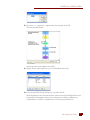
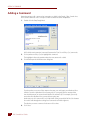

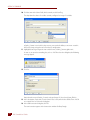
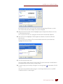
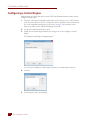

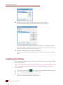
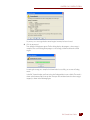
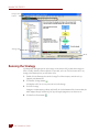
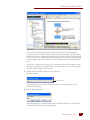


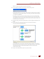
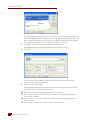


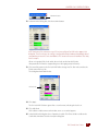
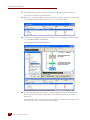
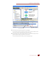

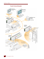


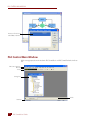
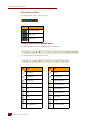
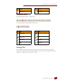
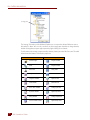
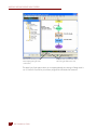


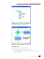


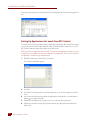
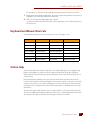


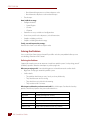

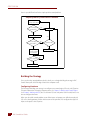
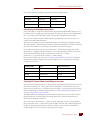
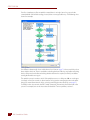
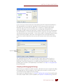

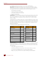
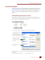
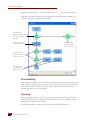
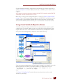


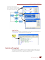


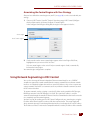


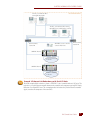
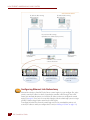

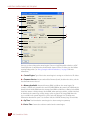

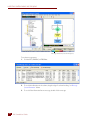
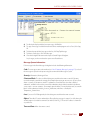
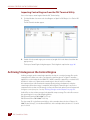

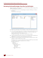


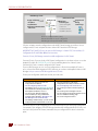
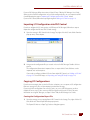


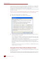
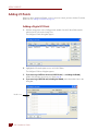
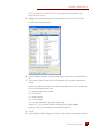

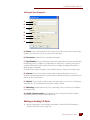


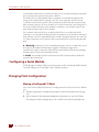
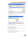
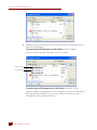
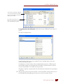


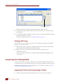
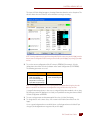
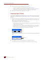
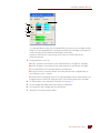

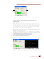

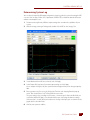

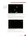
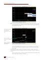

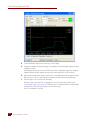


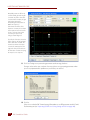


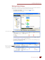

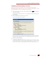


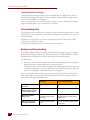

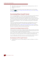
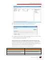
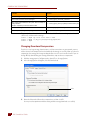
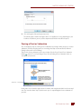


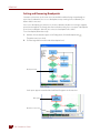
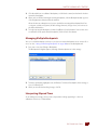
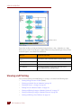
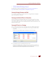

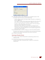
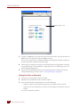
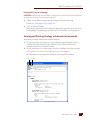


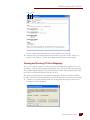


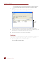
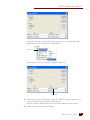


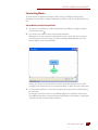


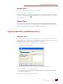
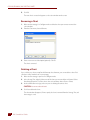
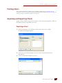

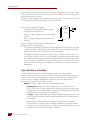


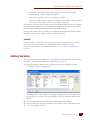


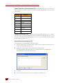
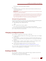


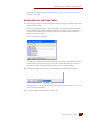
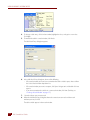

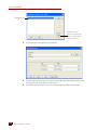


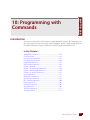


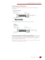
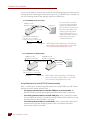
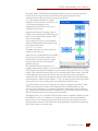
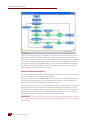


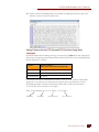

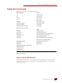
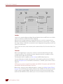


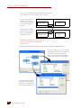


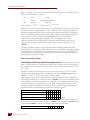
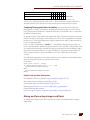


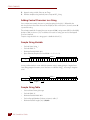
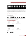

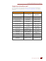
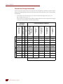
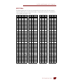


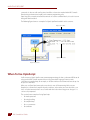

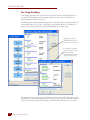


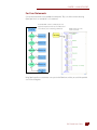


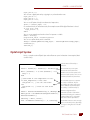


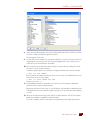
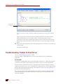


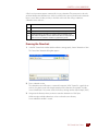
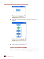
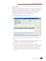
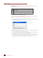

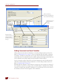


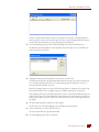


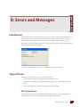


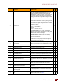


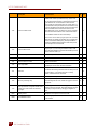


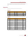


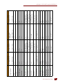
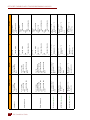
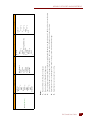


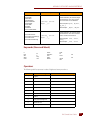


![[ANEXO N°1]](http://vs1.manualzilla.com/store/data/006302967_1-e9ecb6f804c11797b188b7143d3b1bbb-150x150.png)