1
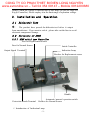
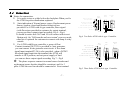
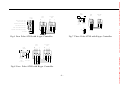
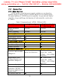
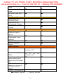
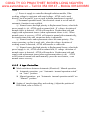
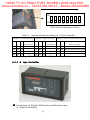
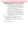
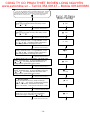
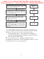
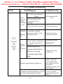
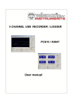
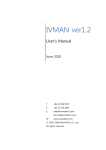
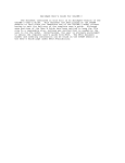
CONG TY CO PHAN THIET BI ÐIEN LONG NGUYEN www.evnonline.vn – Tell 04 354 09147 – Mobile 0912290680 CB Class Automatic Transfer Switching Equipment Compact ATNS User’s Manual CONG TY CO PHAN THIET BI ÐIEN LONG NGUYEN www.evnonline.vn – Tell 04 354 09147 – Mobile 0912290680 Dear Users: Thank you for your selection of our ATNS product. For your safety and correctly application, Please read this manual carefully before Installation, connection, operation and maintenance. The signature followed will be used in this manual for your attention on some danger, Simplify process and key operation :Caution mark, to warn you that incorrect operation may cause people injury or unrecovery damage to the equipment. ;: Key operation, to inform you that incorrect operation may cause controller to work in abnormal state. ": offer some other information and simplify operating process. Caution: This equipment should only be mounted by professionals. The manufacturer shall not be held responsible for any failure to not comply with the instructions given in this manual. CONG TY CO PHAN THIET BI ÐIEN LONG NGUYEN www.evnonline.vn – Tell 04 354 09147 – Mobile 0912290680 Contents 1. Check-up before using .......................................................... 1 1.1 Check after opening the package box............................. 1 1.2 Operation Environment .................................................. 1 1.3 Operation Voltage............................................................ 1 2. Installation and Operation.................................................... 2 2.1 Dielectric Test................................................................. 2 2.2 Structure of ATNS.......................................................... 2 2.2.1 ATNS with A type Controller .................................. 2 2.2.2 ATNS with B type Controller .................................. 3 2.3 Form and Installation Dimensions.................................. 4 2.4 Connection...................................................................... 7 2.5 Controller...................................................................... 10 2.5.1 Main Function ......................................................... 10 2.5.2 A type Controller.................................................... 12 2.5.3 B type Controller ................................................... 13 2.6 Operation ...................................................................... 18 3. Maintenance and common troubleshooting ........................ 19 CONG TY CO PHAN THIET BI ÐIEN LONG NGUYEN www.evnonline.vn – Tell 04 354 09147 – Mobile 0912290680 1. Check-up before using 1.1 Check after opening the package box When receive the ATNS automatic transfer switching equipment (ATSE) you ordered , please check the item followed before your installation • check whether the ATSE is intact , and there is no any man-made damage or transport damage • Check whether the voltage picking up wire connect with the breaker terminal and no wire falling • Check whether all the accessory is available ( refer to Table 1) If some problem is found, Please contact with us. Table 1 Item Certificate Card User’s manual Qty. List of accessory Note 1 ———— 1 ———— Handle 1 For manual operation in emergency Fuse 2 Standby for broken failure 2 Only for B type ATNS 1 Only for B type ATNS Connecting wiring Separated Controller 1.2 Operation Environment • • • The altitude of installing Location shouldn’t be high than 2000m Environment tolerance: ATNS could be used in a temperature range from -25℃ to 55℃. When it is higher than 40℃ , we should consider using them with reduced capacity. It can work in humid environment, even in relative humidity 95% at 55℃ Pollution Class : Ⅲ Protection Class: IP20 1.3 Operation Voltage ATNS can work well in a wide range from 85% to 110% of rated -1- CONG TY CO PHAN THIET BI ÐIEN LONG NGUYEN www.evnonline.vn – Tell 04 354 09147 – Mobile 0912290680 voltage, when the voltage is detected out of this range (or pre-set range for B type Controller). Please employ it in the limit range of operation voltage. 2. Installation and Operation 2.1 Dielectric Test ;: The product have passed the dielectric test before it output from manufacture . If you want to redo it , please take out the fuse to avoid electronic component damage . 2.2 Structure of ATNS 2.2.1 ATNS with A type Controller Fuse for Replacement Source Fuse for Normal Source Inside Controller Output Signal Terminal Indication Lamp Breaker for Replacement source Handle Protection Eearth Terminal Automatic /manual operation switch Breaker for Normal Source " Introduction of Indication Lamp -2- CONG TY CO PHAN THIET BI ÐIEN LONG NGUYEN www.evnonline.vn – Tell 04 354 09147 – Mobile 0912290680 N ( normal power source) Indicator ( Yellow LED): Light up — Voltage of normal power source is ok ; Flickery — there is voltage failure for normal power source R ( replacement power source) Indicator ( Yellow LED): Light up — Voltage of replacement power source is ok ; Flickery — there is voltage failure for replacement power source N breaker indicator ( Green LED) : Light up — Normal source breaker is closed R breaker indicator ( Green LED) : Light up —Replacement source breaker is closed N breaker tripped indicator ( Red LED) : Light up — Normal source breaker is tripped for current fault R breaker tripped indicator ( Red LED) : Light up —Replacement source breaker is tripped for current fault 2.2.2 ATNS with B type Controller Fuse for Replacement Source Fuse for Normal Source Breaker for Normal source Breaker for Replacement source Terminal socket to connect with outside controller Protection Eearth Terminal Automatic /manual operation switch Handle B Type Controller (Individual) -3- CONG TY CO PHAN THIET BI ÐIEN LONG NGUYEN www.evnonline.vn – Tell 04 354 09147 – Mobile 0912290680 2.3 Form and Installation Dimensions For form and dimension of ATNS please refer to the Fig.2 , Fig.3 and Table 2 For form and dimension of B type controller(Individual), please refer to the Fig.1 15 175 75 B Type Controller B型控制器 96 94 100 20 17 0 172 Fig. 1 Form of B type controller and Hole dimension -4- -5- CONG TY CO PHAN THIET BI ÐIEN LONG NGUYEN www.evnonline.vn – Tell 04 354 09147 – Mobile 0912290680 Fig .3 ATNS 100/ 160 / 250 / 400/ 630 ATNS63 Fig . 2 Table 2 Form and installation dimension of ATNS Type installation dimension (mm) Form Dimension(mm) Dimension D G(3P/4P) H H1 K L(3P/4P) L1(3P/4P) P1 P2 P3 P4MAX G1(3P/4P) K1 T ATNS 63 162 160 70.5 220 55.5 170 460 17 130 161 —— 440 190 6.5 ATNS 100 162 177/212 78 220 63 187/222 480/550 20 145 176 131 460/530 190 6.5 ATNS 160 162 177/212 78 220 63 187/222 480/550 20 145 176 131 460/530 190 6.5 ATNS 250 162 177/212 78 220 63 187/222 480/550 20 145 176 131 460/530 190 6.5 ATNS 400 280 242/287 97 285 82 257/302 610/700 20 180 232 188 580/670 255 9 ATNS 630 280 242/287 97 285 82 257/302 610/700 20 180 232 188 580/670 255 9 2 poles product of ATNS 63 has the same demission with 3 poles product -6- 2.4 Connection ■ Notice for connection: It is prefer to tap or solder bolt on the backplate When you fix the ATNS in power distribution cupboard State indication of Normal power source, Replacement power Source ,breaker closed and breaker failure trip are provided. For ATNS with A type controller, these signal (with Power)are provided to customer by output terminal, you can use these output signal according Fig.4—Fig.6, It should be notice that No.9 and 10 is to connect with a reset Button only for "Self-transfer and reset-return" recovery mode, other bits is optional for customer to connect with lamp or relay outside. For ATNS with B type controller, a group of float Contact (terminal 20,21,22) is provided to start generator, you can connect It into generator start circuit. A fire alarm signal input terminal(23,24) is also provided , when a DC24V fire alarm signal input into the terminal, the ATNS will transfer to OFF position, and cut power supply of load. you can use these output signal according Fig.7—Fig.8 ;: The phase sequence connect to normal source breaker and replacement source breaker should be consistent, and for 3 poles ATNS the zero line should be connected to Zero terminal Outpu t termi nal N o rm al s o ur c e p o w er s i gn a l 1 N o rm al po s it io n s ig n al 2 No rm al So ur ce NN U N R ep l ac e m e nt S ou r c e N R UR 3 R ep la c e m en t s ou r ce p o we r s ig n al 4 Re p la c em en t p os i ti on s i gn a l 5 6 N or m a l s id e b re a ke r t r i pp e d si g na l 7 Re p la ce m en t s id e b re a k e r t r i pp e d si g na l 8 9 R es e t bu t t o n 10 Fig.4 Two Poles ATNS with A type Controller Out put te rmi nal Normal source power signal 1 Normal position signal 2 N orma l S ourc e UN VN WN Replacement Source UR VR WR 3 Replacement source power signal 4 Replacement position signal 5 6 Normal side breaker tripped signal 7 Replacement side breaker tripped signal 8 9 Reset button 10 Z ero ter min al PEN N N N Fig.5 Three Poles ATNS with A type Controller -7- O utp ut ter min al Normal source power signal 1 Normal position signal 2 Replacement Source NN UN VN WN N R UR VR WR 2 0 21 2 3 2 4 25 Gener a tor starti n g signa l a t UE s t ate 3 Replacement source power signal 4 Replacement position signal 5 6 Normal side breaker tripped signal 7 Replacement side breaker tripped signal 8 Reset button UR VR WR D C24V f ire alarm si gnal N 9 N 10 N Fig.7 Three Poles ATNS with B type Controller Norma l Sourc e Replac ement N N UN VN WN N R UR VR WR Sou rce termina l 20 21 23 24 25 Generat or st arting s ignal R epla cem ent So urc e Zer o termi nal PEN Fig.6 Four Poles ATNS with A type Controller Ou tput Normal Source UN VN W N DC24V fi re alar m signal at UE state Fig.8 Four Poles ATNS with B type Controller -8- CONG TY CO PHAN THIET BI ÐIEN LONG NGUYEN www.evnonline.vn – Tell 04 354 09147 – Mobile 0912290680 O utp ut ter mina l N orm al S our ce ;: TO generator start terminal (B type Controller),when the normal source power is ok, the ”normal closed contact (terminal 21)” disconnect with the “ Common Contact(terminal 22)”. And when the voltage of normal source is abnormal, the ”normal closed contact” connect with the “ Common Contact”, which can start the generator . To the ”normal opened contact(terminal 20)” the work state is opposite to the ”normal closed contact” . The protection earth line should be well connected to assure safety of operator Electrical parameter of output terminal Terminal Name Controller Type Terminal for Indication Lamp A B Fire alarm Input terminal Generator startup terminal B (Float)* Rated Voltage 220VAC 24VDC Rated Current 1A — 250VAC/ 30VDC 3A * It means rated load capacity for float contact -9- CONG TY CO PHAN THIET BI ÐIEN LONG NGUYEN www.evnonline.vn – Tell 04 354 09147 – Mobile 0912290680 2.5 Controller 2.5.1 Main Function ATNS decide to perform power supply switchover or not based on whether voltage of Power supply is normal and the pre-set working mode. The main function of ATNS is up to its controller, we provide two kind of controller A type and B type, the function of both controller can be refer to Table 3 . Table 3 Function List of ATNS CB level ATS Controller Rated operational Voltage① Rated Frequency 3 working positions Normal Position Replacement Position OFF Position 3 operational modes Automatic Operation Local Forced Operation Manual Operation② Automatic Operation Normal source Voltage detection and automatic changeover A(Internal) 220VAC B(External and individual) 220VAC 50/60Hz 50/60Hz ■ ■ ■ ■ ■ ■ ■ ■ ■ ■ ■ ■(Phase failure 、 power loss detection) □ ■(Phase failure 、 power loss、under – Voltage 、over-voltage detection) ■(Phase failure 、 power loss、under – Voltage 、over-voltage detection) ■ ■ ■ ■ Replacement source Voltage detection and automatic changeover Generator Control Chain action for fire protection(DC24V), cut power supply to nonpriority loads Self transfer and Self - 10 - CONG TY CO PHAN THIET BI ÐIEN LONG NGUYEN www.evnonline.vn – Tell 04 354 09147 – Mobile 0912290680 ③ return Self transfer and Rest ④ return Self transfer and fault ⑤ return Local Forced Operation Forced work on Normal Position Forced work on Replacement Position Forced work on OFF Position Indication Circuit breaker status indication (open or closed) Normal source and Replacement source indicator Tripped indicator Pre-set Parameter Display Other Function Transfer Time Delay Return transfer Time Delay ■ ■ ■ ■ ■ ■ ■ ■ ■ ■ ■ ■ ■ ■ 0s 、5s 、 15s、 30s accuracy ≤5℅ 0-255s (1s as a step) 0s 、5s 、 15s、 30s accuracy ≤5℅ ■ 0-255s (1s as a step) Protection and alarm for ■ wrong connection of phase wire with Neutral pole Time limit for ■ ■ changeover process (5s self –protection for motor) Modbus Communication □ ■ Standard Function □ Optional function - 11 - CONG TY CO PHAN THIET BI ÐIEN LONG NGUYEN www.evnonline.vn – Tell 04 354 09147 – Mobile 0912290680 Note : ① Power is supply to controller through isolation module, If the working voltage is consistent with rated voltage , ATNS can be used directly, but if not an BC type or equal isolation transformer is needed ② In manual operation mode , the electrical circuit is cut off and all automatic function is not available ③ Normal source has high priority to Replacement Source, when both power supply is ok , ATNS work on normal side , If voltage deviation of normal source is detected , ATNS will transfer to Replacement side and supply with replacement source (when replacement source is ok) . When normal source is recovery, ATNS will return to normal side automatically, the transfer time delay and return time delay is adjustable . ④ Normal source and replacement source has same priority . The source powering up first is work side, when the voltage deviation of working source is detected , ATNS will transfer to other side ⑤ Normal source has high priority to Replacement Source, when both power supply is ok , ATNS work on normal side, If voltage deviation of normal source is detected , ATNS will transfer to Replacement side and supply with replacement source(when replacement source is ok) . ATNS won’t return to normal side until manually press the reset button , even normal source recovery 2.5.2 A type Controller ■ Mode switchover between Automatic (Electrical) / Manual operation Automatic operation:put “Automatic /manual operation switch” on “Auto” position Manual operation:put “Automatic /manual operation switch” on “Manual” position ■ Setting of transfer time delay and working ( Adjust the position of DIP switch, refer to Table 4 ) - 12 - CONG TY CO PHAN THIET BI ÐIEN LONG NGUYEN www.evnonline.vn – Tell 04 354 09147 – Mobile 0912290680 ON OFF 1 2 3 4 5 6 7 8 DIP Switch for Parameter Setting Table 4 Operation Parameter Setting of A Type Controller Setting of Tansfer time delay Setting of Return time delay Setting of Recovery mode(working mode) 8 Recovery mode 1 2 3 Time delay(s) 4 5 6 Time delay(s) 7 OFF OFF OFF OFF OFF OFF OFF OFF Self-transfer and Self-return 0 0 ON OFF OFF ON OFF OFF ON OFF Self-transfer and Failure-return 5 5 ON ON OFF ON ON OFF ON ON Self-transfer and Reset-return 15 15 ON ON ON 30 ON ON ON 30 " Please preset the DIP switch before powering up 2.5.3 B type Controller ■ Introduction of Digital LED Display and Indication Lamp Digital LED display - 13 - CONG TY CO PHAN THIET BI ÐIEN LONG NGUYEN www.evnonline.vn – Tell 04 354 09147 – Mobile 0912290680 U(V) Indicator: light up – automatically and alternatively display phase voltage of normal source and replacement source with digital LED UN Indicator: light up – digital LED display the phase voltage of normal power source UR Indicator :lights up – digital LED display the phase voltage of replacement power source t(s) Indicator: lights up -digital LED display countdown of pre-set time delay remained. N (normal power source) Indicator for normal source( Yellow LED): Light up — Voltage of normal power source is ok ; Flickery — there is voltage failure for normal power source R ( replacement power source) Indicator for replacement source( Yellow LED): Light up — Voltage of replacement power source is ok ; Flickery — there is voltage failure for replacement power source N breaker indicator (Green LED) : Light up — Normal source breaker is closed R breaker indicator ( Green LED) : Light up —Replacement source breaker is closed N breaker tripped indicator (Red LED) : Light up — Normal source breaker is tripped for current fault R breaker tripped indicator (Red LED) : Light up —Replacement source breaker is tripped for current fault Fire protection indicator: light up— fire alarm signal has been received Automatic operation indicator: Light up—controller works in automatic operation mode; Flickery —Both power supplies have fault in automatic operation mode Local Forced operation indicator: Light up—controller works in Local Forced operation mode ; Flickery —Both power supplies have fault in local forced operation mode Running indicator: lights up—controller is in normal operation state System setting indicator: lights up—controller is in state of parameter setting - 14 - CONG TY CO PHAN THIET BI ÐIEN LONG NGUYEN www.evnonline.vn – Tell 04 354 09147 – Mobile 0912290680 ■ Operational Keyboard Reset Key: controller reset, to return to normal source side in Rest return working mode or when controller is abnormal ↵ Enter Key: In Running state —operation mode switch key between automatic operation mode and local forced operation mode;In System setting state —key of confirmation , when you press it the parameter you set is saved in memory and step into next parameter setting item ↑ Up Key(Non):In local forced operation mode—press it to command to supply power with normal power source;In System setup state ---Press to increase the number you set ↓ Down Key(Ron):In local forced operation mode—press it to command to supply power with replacement power source; In System setup state —Press to decrease the number you set OFF Key: In local forced operation mode—press it to command to open both of two breaker and no power supply to load, ATNS work in off position ■ Electrical operation and manual operation switching Electrical operation mode : push the “manual /electrical operation switch” to “Automatic” position manual operation mode : push the “manual /electrical operation switch” to “Automatic” position , and it will make the electrical circuit to be open ■ Parameter setting procedure - 15 - CONG TY CO PHAN THIET BI ÐIEN LONG NGUYEN www.evnonline.vn – Tell 04 354 09147 – Mobile 0912290680 Enter to system setup menu Press the key RESET and key ENTER simultaneously, and then release the key RESET first, when the system parameters “1-XX” are indicated on the LED, release the key ENTET,and SYSTAM SETUP LED is on, then press“ ” enter into setup menu. 1 N > R Transfer time delay Setting 0-255 seconds transfer time delay via the key “ ”&“ ” 000 Press ENTER key for storage, it will enter into next item 2 R > N Recovery time delay Setting 0-255 seconds recovery time delay via the key “ ”&“ ” 000 Press ENTER key for storage, it will enter into next item 3 Normal source over- voltage threshold value Setting threshold value in range 230-280V via the key “ ”&“ ”, according which to determine over-voltage fault of normal power source 3 250 Press ENTER key for storage, it will enter into next item 4 Normal source under- voltage threshold value Setting threshold value in range 180-210V via the key “ ”&“ ”, according which to determine under-voltage fault of normal power source 180 Press ENTER key for storage, it will enter into next item 5 Replacement source over- voltage threshold value Setting threshold value in range 230-280 via the key “ ”&“ ”, according which to determine overvoltage fault of replacement power source 250 Press ENTER key for storage, it will enter into next item 6 Replacement source under- voltage threshold value Setting threshold value in range 160-180V via the key “ ”&“ ”, according which to determine undervoltage fault of replacement power source 180 Press ENTER key for storage, it will enter into next item 7 Recovery Mode Setting AA/NA/NN recovery mode via the key “ ”&“ ”, AA means “ Self-transfer and Self -return” ; NA means“ Self-transfer and Fault return”; NN means “ Self-transfer and Reset -return” -AA Press ENTER key for storage, it will enter into next item 8 Double Power source type Setting UU ( net to net) /UE( net to generator) power source type via the key “ ”&“ ” Press ENTER key for storage, it will enter into next item - 16 - -UU CONG TY CO PHAN THIET BI ÐIEN LONG NGUYEN www.evnonline.vn – Tell 04 354 09147 – Mobile 0912290680 9 Normal source Voltage detecting Calibration Adjust voltage display via the key “ ”& “ ” , until the value approach to the actual UN value detect by high level precision voltage-meter 220 Press ENTER key for storage, it will enter into next item 10 Replacement source Voltage detecting Calibration Adjust voltage display via the key“ ”& “ ”, until the value approach to the actual UR value detect by high level precision voltage-meter 220 Press ENTER key for storage, it will enter into next item 10 Replacement source Voltage detecting Calibration Adjust B Timevoltage delay setting displayfor viatransfer the key“ to OFF ”& “ position ”, until the To set value time approach delay transfer to the actual to OFFUR position value detect via theby high level key“precision ”& “ voltage-meter, ”, 0-80*0.02spress key ENTER to storage and go back to working condition 045 Press ENTER key for storage, it will enter into next item C OFF position feed back signal To Set whether there is OFF position feed back signal or not, via the key“ ”& “ ”. “on” mean there is OFF position signal and “OF” means no, it is just for controller compatibility , press ENTER key to save and go back to running state ": In the parameter setting procedure , if the followed parameter item needn’t to be adjusted , you can press Reset button to go back to running state directly after press Enter button to save the last setting. ": In the procedure above, the number inside rectangle provide the default parameter setting ( except item 9 & 10 base on actual voltage value) ;: For parameters from 1-8 , customer can adjust freely according you requirement ; but for parameters from 9-C is just for professionals or our service people supporter - 17 - CONG TY CO PHAN THIET BI ÐIEN LONG NGUYEN www.evnonline.vn – Tell 04 354 09147 – Mobile 0912290680 2.6 Operation ATNS is easy to use , To customer, you just need to connect the wiring of input side (power source side) and out put side( load side),and adjust the parameter according chapter 2.5.2( for A type controller) or chapter 2.5.3( for B type controller), if the default value not fit for your requirement . Of cause the adjustment operation can be omitted if you accept the default value. Then to check the whether the “Automatic /manual operation switch” is on “ Auto” position , if no change it to “ Auto “ position , After powering on the ATNS can work automatically . ■ Automation Operation To choose “Self-transfer and Self return ”work mode as an example. After assembling all the wiring of input side and output side according the correspond Figure of Chapter 2.4 replacement side. When everything is ready, including the wiring is well connected , the “Automatic /manual operation switch” is on “Auto ” position, controller is pre-setted on “Selftransfer and Self return ” recovery mode. After powering on, if the normal source is ok , ATNS will work on normal position , otherwise ATNS will transfer to replacement position (when replacement source is ok) , when the normal source power recovery ,ATNS will return to normal position after preset return time delay. ■ Local forced operation(only for ATNS with B type controller ) When either source power is ok and “Automatic /manual operation switch” on “Auto ” position . You can press the “↵ “ button to switch the operation mode between two kind of electrical operation “Automatic operation mode “ and “ Local forced operation mode” . In the “ Local forced operation mode” ( the Local Forced operation indicator will light up) , you can press the “↑(Non)” key to close the normal side breaker and press the “↓(Ron)” key to close the replacement side breaker , or press “OFF” key to open two breaker and make ATNS work on “OFF” position ■ Manual Operation Push the “Automatic /manual operation switch” to “Manual ” position , which will cut off the electrical driving circuit, then to insert - 18 - CONG TY CO PHAN THIET BI ÐIEN LONG NGUYEN www.evnonline.vn – Tell 04 354 09147 – Mobile 0912290680 the Handle and press it to bottom, after that you can rotate the handle to close the breaker and choose the power source you want . The manual operation just for maintenance or emergency ;: When breaker is tripped for overload or short circuit , first to remove the failure, then re-trip the breaker manually , push the “ “Automatic /manual operation switch” to “Auto” position and press the Rest button, then the controller will recovery to normal running state ;: After manual operation , if you want return to automatic operation state , please take out the handle and push the “Automatic /manual operation switch” on “Auto” position ,then press the Rest button Don’t plug in or took out the terminal when power is on Don’t close the breaker when both power source are fault 3. Maintenance and common troubleshooting ■ Maintenance To assure the reliability of ATNS , please have routine source changeover test in fixed interval (every 3 month is preferred) . It will benefit to continuity of power supply to important loads. ■ Common Troubleshooting When your find ATNS works in abnormal state, please press the Reset button first to see whether the fault could be removed, then to check whether the state of main circuit and Voltage picking up wire is normal and well connected . The table 5 is useful for you fault diagnose and removing. After checking refer to the table , if you still can’t remove the fault , please contact with our company or local service department . ] - 19 - CONG TY CO PHAN THIET BI ÐIEN LONG NGUYEN www.evnonline.vn – Tell 04 354 09147 – Mobile 0912290680 Table 5 Common Troubleshooting Fault Fault Diagnose Voltage Picking up wire fall off from input terminal of breaker To 3 Poles ATNS , the Source zero wire hasn’t been indicator connected to Zero on the controlle terminal r is off The related fuse is broken Source indicator is lighting on ATNS is Powered on Bu t doesn’t work well Source indicator is flickerin g “Automatic /manual operation switch” on the manual position The voltage of related power source is abnormal or the wire connection is not well Fault Removing Well connected the wire Change related fuse Push the switch to Automatic position Maintain the power source or wire connection Buzzer alarm that means neutral Pole (or terminal ) is wrong connected with phase Modify the wrong connection pole Breaker tripped indicator lights up Automatic operation indicator or Local forced operation indicator flickers - 20 - The related breaker is tripped , when the current failure have been removed, re-trip the breaker manually ,and press the Reset button Both of the two power source are failure, check and remove the failure Copyright Reserved CONG TY CO PHAN THIET BI ÐIEN LONG NGUYEN www.evnonline.vn – Tell 04 354 09147 – Mobile 0912290680 Schneider Electric China www.schneider-electric.com.cn Schneider Building, Chateau Regency, No.2 Jiangtai Road,Chaoyang District Beijing 100016, China Tel: (010) 8434 6699 Fax: (010) 8450 1130 As standards, specifications and designs change from time to time, The introduction and pictures of this manual should not be looks as contractual file. This document has been printed on recycled paper. 2006.04