1
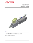
2 Description 2.1 Theory of Operation The LED flood array consists of 144 reflectorized LED’s that produce an effective curing area of approximately 100mm x 100mm. The housings are designed to be stackable side by side without creating “dark”spaces between units. The controller/power supply, (not included), provides electrical power to the LED’s through the connecting cable, (not included). Indicator lights located on the front panel of the power supply provide visual confirmation that the LED’s are in or out of their acceptable range. In the event of temperature fault the power supply will automatically shut down to protect the LED array. When the cure cycle is initiated, light is immediately irradiated at or near maximum intensity from the LED’s. The LED arrays are available in three different wavelengths to match the absorbing properties of the Loctite® adhesive, and thereby maximize the efficiency of the curing process. The wavelengths available are: 375 nm (Part # 1167582) Intended for use with Loctite® UV curing products 405 nm (Part # 1167593) Intended for use with Loctite® UV/VIS curing products Indigo (Part # 1167589) Intended for use with Loctite® Indigo™ product line The curing process begins when the adhesive is placed under the LED’s. The two primary variables that control the curing process are the time of exposure and the strength of the light, (irradiance). For a given irradiance, the exposure time required to fully cure the adhesive depends primarily on the properties of the adhesive and the optical properties of the substrate that the light is transmitted through. 2.2 Product Features Typical Irradiance: o LED Flood Array 375 nm: 300 mW/cm2 o LED Flood Array 405 nm: 600 mW/cm2 o LED Indigo® wavelength: 600 mW/cm2 Instant On/Off (no warm-up time required like traditional arc lamp systems). 3 Operating the Unit 3.1 Electrical Connections (With No AC Power To Unit) - Plug one end of the power cable into the 15 pin D-sub connector located on the rear panel of the LED housing. Plug the opposite end into the 15 pin D-sub connector located on the rear panel of the power supply. Make sure that the connections at both ends are secure. - For manual operation, plug the footswitch into the 9 pin D-sub connector marked “Start Signal Input and Fault Output”located on the rear panel of the power supply. 3