1
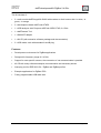
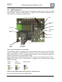
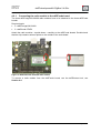
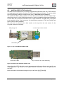
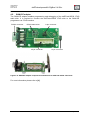
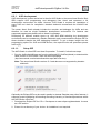
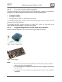
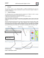
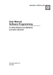
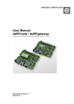
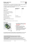
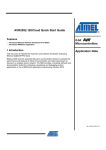
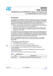
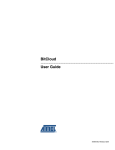
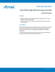
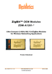
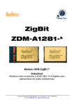
User Manual Version 1.0 2013-02-28 deRFdevelopmentKit ZigBee 2.4 GHz Figure 34: Pinout for 10pin AVR JTAG header 6.2.1.4. Connecting the target To program a device, the programmer must be connected to the respective JTAG header and the target needs to be powered. On the different dresden elektronik products, several JTAG programming headers are available: 10-pin AVR-JTAG header, 10-pin AVR-JTAG mini header (pin-compatible), Note: Not all boards (e.g. RCBs, deRFmodules) have a JTAG header. In those cases an additional board may be required for providing this header (e.g. Sensor Terminal Board, deRFnode, deRFbreakout Board). Figure 35: AVR JTAGICE mkII connected to deRFmega128 plugged onto a deRFnode Note: The blue cable is not required for programming. It connects to a dresden elektronik USB level shifter stick to a PC for serial debug output. Although not required, a trace (debug output) connection is largely helpful for any embedded development. www.dresden-elektronik.de Page 42 of 66