1
International Journal of Emerging Technology and Advanced Engineering
Website: www.ijetae.com (ISSN 2250-2459, ISO 9001:2008 Certified Journal, Volume 4, Issue 3, March 2014)
C. The CAN error process
The error is detected by the CAN controller (a
transmitter or a receiver). An error frame is immediately
transmitted. The message is cancelled at all nodes
(exceptions exist - see CAN controller error modes). The
status of the CAN controllers is updated (see CAN
controller error modes). The message is re-transmitted. If
several controllers have messages to send, normal
arbitration is used.
i.
Error detection
Error detection is handled automatically by the CAN
controller. The detected errors are:
Bit errors:
1. Bit stuffing error: normally a transmitting node inserts a
high after five consecutive low bits(and a low after five
consecutive high). This is called bit stuffing. A receiving
node that detects violation (more than five consecutive bits
will see a bit stuffing violation.
2. Bit error: A transmitting node always reads back the
message as it is sending. If it detects a different bit value on
the bus than it sent, and the bit is not part of the arbitration
field or in the acknowledgement field and error is detected.
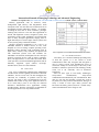
Fig. 2 CAN Remote Frame Types
In case that several nodes within one system start a
simultaneous transmission of message frames with the
same identifier, the following rules are valid: Data frames
have a higher priority than remote frames, and standard
frames have a higher priority than extended frames. That
means that e.g. a standard remote frame wins arbitration
against an extended data frame, if the 11 most significant
bits of the identifiers are equal.
Message errors:
1. Checksum error: each receiving node checks CAN
messages for checksum errors.
2. Frame error: There are certain predefined bit values that
must be transmitted at certain points within any CAN
Message Frame. If a receiver detects an invalid bit in one
of these positions a Form Error (sometimes also known as a
Format Error) will be flagged.
3. Acknowledgement Error: If a transmitter determines that
a message has not been acknowledged then an ACK Error
is flagged.
B. CAN and OSI Model
Many communication bus protocols do not use all the
seven layers of this OSI Model. Since CAN is a closed
network it doesn’t need to have security and to present the
data in a user interface. Also it does not need to maintain
sessions and logins. Hence it uses only two Layers such as
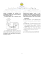
Physical and Data Link Layer. The CAN OSI model shown
in fig. 3 explains the transfer of data between two nodes.
ii.
Fig. 3 CAN and OSI model
The Physical Layer ensures the physical connection
between the nodes in the network. The Data Link layer
contains Frames and information to identify the frames and
errors. It has information also to determine the bus access.
371
CAN controller error modes
A CAN controller can be in one of three states:
1. Error active: the normal operating mode for a
controller. Messages can be received and transmitted. On
detecting an error an active error flag is sent (see error
signaling).
2. Error passive: a mode entered when the controller has
frequent problems transmitting or receiving messages.
Messages can be received and transmitted. On detecting an
error while receiving, a passive error flag is sent.