1
XVME-244 Manual
December 1992
2.2.4
Output
Connectors
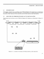
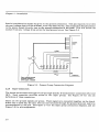
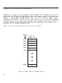
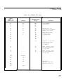
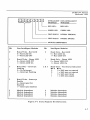
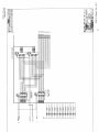
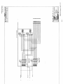
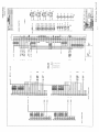
The outputs are accessed through two 44-pin high-density D subminiature connectors (JK3 and
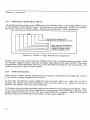
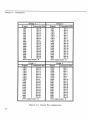
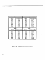
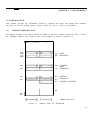
JK4). Each connector provides access to two output groups. Figure 2-4 shows the pin
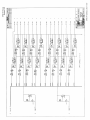
definition of these connectors. (Refer to Figure 2-3 for output signal information).
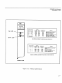
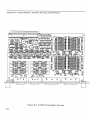
Figure 2-4. Front View of 44 Pin D Subminiature Connector
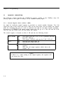
Each group requires 19 pins:
8
1
9
1
Output signals
Test signal
Power supply (all tied together)
Power supply ground reference
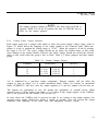
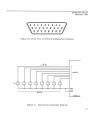
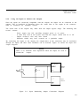
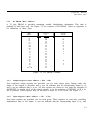
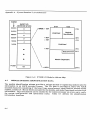
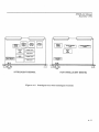
When an output is turned on, current will flow from the power supply pins and come out
through the output pin. See Figure 2-5.
When an output is turned off, a small (leakage) current will try to flow out of the output. This
will raise the potential of the output to the power supply voltage level (if there is no load on
the output). The test signal provides a bias which may be used as a pulldown resistor for
system level debugging. When this is connected to an output, the output will assume the ground
potential when it is turned off.
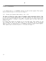
The test signal may also be used to test the state of the power fuse for that particular group.
If the resistance between the test and ground pins is less than l0K, then the fuse is intact. If
the reading is greater than l0K, then the fuse has been blown and needs to be replaced.
There are nine power pins per group. The pins are all connected together on the board. The
current supplied from the output pins is drawn from these power pins. The number of power
pins depends on the total current supplied through that group’s outputs. The current should
be limited to a maximum of one ampere per pin. Use this limitation to select the number of
power pins to be used in a given application. For example, if each output within a group may
source 400 mA, a total of 3.2 amperes will be required from the power supply. In this case, a
minimum of four power pins should be used. A total of nine power pins are provided to allow
more wire connections in order to decrease the voltage drop across the power supply wires.
When excessive voltage drop is experienced, more connections can be made (to a maximum of
nine).
2-5