1
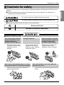
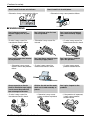
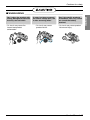
Visit us at : http://www.lgservice.com
ITALIANO
LG
Power Distribution
Indicator
ENGLISH
LG
OWNER'S & INSTALLATION MANUAL
ESPAÑOL
Models: PQNUD1S00
FRANÇAIS
DEUTSCH
IMPORTANT
CHINESE
• Please read this user's manual completely
before installing the product.
• Installation work must be performed in
accordance with the national wiring standards
by authorized personnel only.
• Please retain this user's manual for future
reference after reading it thoroughly.
Power Distribution Indicator Owner's & Installation Manual
TABLE OF CONTENTS
FOR YOUR RECORDS
Cautions for safety ......................3
Overview ......................................6
Available Watt-hour meter ..........7
Write the model and serial numbers here:
Model #
Serial #
You can find them on a label on the side of each unit.
Dealer's Name
Wiring Diagram ..........................10
Date Purchased
Installation ..................................11
■ Staple your receipt to this page in the event you need
to prove date of purchase or to issue warranty.
How to set interface unit ...........17
How to set each Indoor Unit
for Multi V ...................................18
Installation Guide.......................20
Usage .........................................21
READ THIS MANUAL
Inside you will find many helpful hints on how to use
and maintain your Power Distribution Indicator properly.
Just a little preventive care on your part can save you a
great deal of time and money over the life of your
Power Distribution Indicator.
You'll find many answers to common problems in the
chart of troubleshooting tips. If you review our chart of
Troubleshooting Tips first, you may not need to call
for service at all.
PRECAUTION
• Contact the authorized service technician for repair or
maintenance of this unit.
• Contact the installer for installation of this unit.
• The air conditioner is not intended for use by young
children or invalids without supervision.
• Young children should be supervised to ensure that
they do not play with the air conditioner.
• When the power cord is to be replaced, replacement
work shall be performed by authorized personnel only
using only genuine replacement parts.
• Installation work must be performed in accordance with
the National Electric Code by qualified and authorized
personnel only.
2 Electricity Distribution Indicator
Cautions for safety
Cautions for safety
This symbol indicates the possibility of death or serious injury.
This symbol indicates the possibility of injury or damage to properties only.
■ Meanings of symbols used in this manual are as shown below.
Be sure not to do.
Be sure to follow the instruction.
■ WHEN INSTALLING
You should always request
product installation to our
Service Center or to
installation expert agency.
• Otherwise it may cause
fire hazard, electric shock,
explosion, injury or
damage.
Use specified parts.
• Or else it may cause fire
hazard, electric shock,
explosion, injury, damage
and trouble failure.
When reinstalling an existing
installed product, request it to
our Service Center or to
installation expert agency.
• Otherwise it may cause fire
hazard, electric shock,
explosion, injury or damage.
SPECIFIED
PARTS
Don’t keep or use ignitable gas or any other
flammable material in vicinity of the product.
• Otherwise it may cause fire hazard and
product trouble failure.
Benz
Don’t disassemble, repair and modify the
product at your will.
• Or else it may cause fire hazard and electric
shock.
ene Ether Thinner
User’s Manual 3
ENGLISH
To prevent injury to the user or other people and property damage, the following instructions must be
followed.
■ Incorrect operation due to ignoring instruction will cause harm or damage. The seriousness is
classified by the following indications.
Cautions for safety
Don’t install it where rain falls on.
Don’t install it in humid place.
• Otherwise it may cause product failure.
• Otherwise it may cause product failure.
■ WHEN USING
Don’t change or extend
electric supply wire at your
will.
• Or else it may cause fire
hazard and electric shock.
Don’t spill water into interior
of the product.
• Otherwise it may cause
electric shock and product
failure.
Always request to our Service
Center or installation expert agency
in such case as the product has
been submerged under water.
• Or else it may cause fire
hazard and electric shock.
Don’t let there exist fire heat
near the product.
• Otherwise it may cause fire
hazard.
Don’t put heavy material upon
electricity supply chord.
• Or else it may cause fire
hazard and electric shock.
Child or the old and the weak
shall use it under custody of
patron.
• Otherwise it may cause
safety accident or product
failure.
4 Electricity Distribution Indicator
Don’t use heat equipment
near the electricity supply
line.
• Or else it may cause fire
hazard and electric shock.
Don’t put heavy material
upon the product.
• Or else it may cause
product trouble failure.
Don’t give impact to the
product.
• If the product is impacted,
it may cause product
trouble failure.
Cautions for safety
■ WHEN USING
• Or else it may cause fire
hazard and product
deformation.
If water has been smeared
on electric charge part, use
it after removing water.
• Or else it may cause
product failure.
Don’t let metallic products
of necklace, coin, key, watch
etc. touch the battery
terminal.
• Or else it may cause product
failure and injury.
x
Wa Thinner
User’s Manual 5
ENGLISH
Don’t clean the product with
strong detergent of solvents
but only use soft cloth.
Overview
Overview
■ Functions
• Accumulation of total power consumption
• Indication of current power in use
• Indication of accumulated power for period
• Indication of standby power (option setting)
■ Specification
• Power Supply: 220~240V AC 50/60HZ 1Ø
• Dimension: 200mm (W) X 120mm (H) X 55mm (D)
• Connectable Units: 1 Outdoor Unit per Electric Power Distribution Indicator.
■ Count Method for Electric Power Distribution
• Power Consumption of each Indoor Unit = Power Consumption of Outdoor Unit x [Weighting Power of each
Indoor Unit / Weighting Power of total Indoor Units]
• Weighting Power of each Indoor Unit = Operation (On/Off) x [ Capacity of Indoor Unit X LEV open rate X Fan
step of Indoor Unit ]
6 Electricity Distribution Indicator
Overview
■ Parts of a PDI
ENGLISH
1
2
3
4
5
6
1. Indicator LCD Display
2. Name Plate of each room
3. Menu Button
4. Up and Down Button
5. Right Shift Button
6. SHIFT Button for LCD Screen Change
Available Watt-hour meter(Local purchase)
• Use the digital watt meter which send the pulse signal depending on the power consumption.
• Use watt meter of 1W/pulse, 2W/pulse, 4W/pulse, 6W/pulse, 8W/pulse or 10W/pulse
(pulse width: 40 –400 msec).
User’s Manual 7
Wiring Diagram
Wiring Diagram
■ Independent operation of PDI
- Connect the product as shown in the below connection diagram
1. Multi V (1Outdoor with less than 16 Indoors)
3Ø 380VAC or
1Ø 220VAC
Watt meter
In this case, please set the product "Unit" [00]
00000000
Master1W/p
MICRONIC
NO- STBP
Pulse type
PDI
1Ø
220VAC
Multi V Outdoor unit
(00)
(01)
(02)
(03)
Indoor unit address setup
2. Multi V (In case of setting more than 16 Indoors) or Multi
3Ø 380VAC or
1Ø 220VAC
Watt meter
In this case, please set the product "Master"[11]
11000000
Master1W/p
MICRONIC
NO- STBP
Pulse type
PDI
1Ø
220VAC
PI-485
Multi V Outdoor unit
(00)
(01)
(02)
(03)
Indoor unit address setup
❈ NOTE : In connecting MPS product
PI-485 must be connected for PDI. (PI-485 must be purchased separately.)
8 Electricity Distribution Indicator
Wiring Diagram
■ Operation with PC Central controller
In this case, please set the
product "Slave"[10]
Watt meter
10000000
Master1W/p
MICRONIC
NO- STBP
3Ø 380VAC or
1Ø 220VAC
PDI
PI-485
Multi/ Multi V Outdoor unit
(00)
(01)
(02)
In this case, please set the
product "Slave"[10]
(03)
Indoor unit
address setup
Watt meter
10 000000
Master1W/p
MICRONIC
NO- STBP
PDI
PI-485
Multi/ Multi V Outdoor unit
(7C)
(7D)
(7E)
(7F)
Indoor unit
address setup
❈ NOTE : PI-485 must be connected for PDI.
(PI-485 must be purchased separately.)
G/W(PNF-G14B0)
PC central controller
with PDI.
When CNU power off or out of order with PC central controller, the PDI can not distribute the power
consumption.
User’s Manual 9
ENGLISH
- Connect the product as shown in the below connection diagram.
Internal Wiring Diagram
Internal Wiring Diagram
■ Install the product as per the following wiring diagram
Multi / Multi V
Outdoor unit
PI-485
...
PDI
Indoor unit
220~240VAC
1P, 50/60Hz
Watt meter
PI-485 communications A/B or
MultV/MultiV PLUS A/B
[ B->B / A->A ]
CN_OUT FAN
CN-WATTMETER
CN-POWER
WHITE BLACK
B
A
The color and polarity of the communications line can differ
from what’s indicated on the PCB depending on the
manufacturer of watt meter. [ Black -> (+), white -> (-) ]
• Turn on the power after connecting the product.
10 Electricity Distribution Indicator
WHM
Installation
Installation
1. You must start the key operation within 10 minutes after
turning on the power for setting options.
2. When you press the Menu and Shift key at the same time,
the following option screen will be shown.
Initial Screen
ELECTRIC POWER
DISTRIBUTOR
Press Menu and Shift
at same time
Option setup screen
00000000
00000000
Unit 1W/p
MICRONIC
NO- STBP
• Product selection
When the first two digits flash, you can use the ▲ or ▼ key to set the product.
[00] -> Unit (When using in connection with Independent operation of PDI and MultiV / MultiV PLUS)
[10] -> Slave (when using in connection with PC central controller)
[11] -> Master (when not using in connection with PC central controller)
*Note : [00] is not using the PI-485, but [10]/[11] are using the PI-485.
Ex) Product selection: Master, Watt meter: 1W/1 pulse
[11] : Independent operation of PDI
11000000
Master1W/p
MICRONIC
NO- STBP
User’s Manual 11
ENGLISH
How to set Option
Installation
- After setting the product, press
to select the next option.
LGAP
Press the
key to set up
the Option for remote
reading service company
selection.
• Remote reading service company selection
(Don't care selecting remote reading service ID.)
- When two digits flash, use the ▲ or ▼ key to select the remote reading service
company.
[00] -> MICRONICS
[10] -> CI-TOPIA
/ [01] -> LSIS-COM
/ [11] -> OMNI-SYS
[00] .
11000000
Master1W/p
MICRONIC
NO- STBP
✱ This setting does not care to use PDI
- After setting the product, press
12 Electricity Distribution Indicator
to select the next option.
Installation
- After setting the product, press
to select the next option.
ENGLISH
LGAP
Press the
key to set up
the option for watt meter
selection.
• Watt meter selection
- When the third 3 digits flash, use the ▲ or ▼ key to select the meter constant of the
watt meter.
[000] -> 1 W/ P
[010] -> 4 W/ P
[100] -> 8 W/ P
/ [001] ->
/ [011] ->
/ [101] ->
2 W/ P
6 W/ P
10 W/ P
Ex) Product selection: Master, watt meter: 2W/ pulse
Not used
[001] is set to 2 W / 1 pulse and shows the
meter constants of the watt meter
11000010
Master 2W/p
MICRONIC
NO- STBP
- After setting the product, press
to select the next option.
User’s Manual 13
Installation
LGAP
Press the
key to select
the option for standby
power.
• Standby power indication selection
- When the forth digit flashes, use the ▲ or ▼ key to select the standby power.
[0] NO-STBP -> Does not show the standby power
[1] CAL-STEP -> Shows the standby power
• Note : If the PDI has been set Slave in previous option selection then Certainly Set
NO-STBP
Ex) Product selection: Master, standby power indication selection
[1] is set to CAL-STBP and
shows you the standby power.
11000001
Master 1W/p
MICRONIC
CAL- STBP
✱ What is standby power selection function?
: Standby power refers to the electric power consumed by the product after the
operation of the product is turned off.
It is the function of separately saving the power consumed when all heating and
air conditioning indoor units are turned off.
14 Electricity Distribution Indicator
Installation
ENGLISH
LGAP
3. After setting the option, press the Shift key to enter the
remote reading service ID setup mode.
(In case of selecting reading service ID in )
• This function is applicable to only korean market (Domestic)
So, skip this setting in the procedure for overseas market
Press the "SHIFT" key
- When the first two digits flash, use the s or t key to select the remote reading service ID by company.
CI-TOPIA ID setup
OUT DR ID(CITOPIA)
XX
OMNI SYS ID setup
OUT DR ID(OMNI-SYS)
XXXX
MICRONICS ID setup
OUT DR ID(MICRONIC)
XX
LS lS ID setup
OUT DR ID(LSIS)
XXXX
✱ When setting the remote reading service ID, enter the remote reading service ID
assigned by the remote reading service company.
4. After entering the remote reading service ID, press the Shift
key to enter the indoor address selection mode.
(In case of the selecting "Master/Slave")
User’s Manual 15
Installation
Press the Shift key to enter the
indoor selection mode
Initial Screen
(Start)
->
(End)
(00)
->
(00)
LGAP
• You can select the option for indoor address selection mode only when
Master / Slave is selected.
• You can distribute the using power to maximum of 48 indoor units.
(When showing the stand by power, maximum of 47 indoor units.)
Ex 1) Distribution of using power to 64 indoor units
(central control address 00-2F)
(Start)
->
(End)
(00)
->
(2F)
* NOTE 2) : When operating in connection to the PC central controller, the range of the indoor address
setup (Start – End) on the power indicator is from 00 to 7F.
The Start and End address of the power indicator refers to the first and last address of the
indoor unit group.
Ex) Indoor address "72", "73", "74", "75" ➠
Start address: 72 End address: 75.
- Press the Menu key to save the remote reading service ID and return to the initial screen
16 Electricity Distribution Indicator
How to set Interface unit
How to set Interface unit
P1485(M) DIP Switch Configuration
ON KSDO 4H
L1 2 3 4
ON KSDO4H
Select Network
Type
* LGAP : LG Air conditioner Protocol
Multi V & Multi(LGAP applied) products Configuration Methods
ON KSDO4H
ON KSDO4H
ON KSDO4H
1 ON, All others OFF: Multi V products(Except CRUN products) or
Multi(Non-Inverter) Product applied Common PCB(Refer to
NOTE) or Multi(Inverter) Product + Central Controller(All
types) - Without LGAP
1 and 4 ON, All others OFF: Multi V products(Except CRUN products)
or Multi(Non-Inverter) Product applied Common PCB or
Multi(Inverter) Product + Central Controller(All types) Using LGAP
2 ON, All others OFF: Multi(Non-Inverter) Product
+ Centroller(All types) - Without LGAP
ON KSDO4H
2 and 4 ON, All others OFF: Multi Non-Inverter Product
+ Central Controller(All Types) - Using LGAP
ON KSDO4H
1,2,3,4 ON : Multi V CRUN Product
+ Central Controller(All types) - Using LGAP
* Please refer the corresponding Central Controller installation manual if you want to know whether
your Central Controller is compatible with LGAP or not.
CAUTION:
The wrong setting of air-conditioner switch could cause malfunctioning.
Switch setting must be done carefully.
Push the Reset button after changing the Dip switch.
NOTE: Multi(Non-Inverter) Product applied Common PCB
PCB P/NO. : 6871A20917*
P/NO. : 6871A20918*
P/NO. : 6871A20910*
*Note : LGAP is special protocol using on LG Air-conditioner for central control.
User’s Manual 17
ENGLISH
Select Air
Conditioner Type
How to set each Indoor Unit
How to set each Indoor Unit
■ Using wired remote controller
AUTO SWING
OPERATION
SET TEMP
Room Temp
Operation unit
03
Timer
Cancel
Program
Week
SUB FUNCTION
HI
MED
LO
AUTO Heater
Defrost
JET
Filter
ZONE
1 2
Time
Timer
On Off
Set no. Time 01
FAN SPEED
Preheat
Humidify
Out door
3 4
Program set
05
07
09
11
13
15
17
19
21
23
1. Press the "Program" &
"Set/Clr" keys at the same
time.
2. Set up the indoor address
using the temperature
adjustment key
☛ Setup range: 00-7F
Holiday
Program
Plasma
3
A
Set/Clr
Hour
Min
RESET
Group No. Indoor No.
Set/Clr
3. Press the "Program" & "Setup/Clr" keys at the same time
for 3 seconds to set up the indoor address.
• The room address on the PDI is listed in the ascending order of indoor number.
Ex) If the indoor addresses are "7C", "7D", "7E" and "7F", the order of the indoor unit on the
PDI are "1", "2", "3" and "4".
• The indoor numbers must be entered in sequence to be accurately recognized in the PDI.
Ex) Correct indoor unit address setup: "01", "02", "03" (setup in order)
Incorrect indoor unit address setup: "01", "02", "06"
18 Electricity Distribution Indicator
How to set each Indoor Unit
■ When using the wireless remote controller
1) ① Press the top left button for more than 3 seconds.
➁ While the top left button pressed, press the Reset button.
The wireless remote controllers have different shapes
according to the model.
2) By using the temperature adjustment button, set the indoor
unit address.
Setting range: 00~FF
3) After setting the address, press the ON/OFF button toward
the indoor unit 1 time.
ON
OFF
SET
CANCEL
4) The indoor unit will display the set address to complete the
address setting. (The address display time and method can
differ by the indoor unit type.)
Temperature
adjustment
PLASMA
5) Reset the remote controller to use the general operation mode.
2. Address check mode
1) With the top right button pressed, press the Reset button.(Press the left button for more than 3 seconds.)
2) Press the ON/OFF button toward the indoor unit 1 time, and the indoor unit will display the set address
in the display window. (The address display time and method can differ by the indoor unit type.)
3) Reset the remote controller to use the general operation mode.
❉ The above function might not work for some remote controllers depending on the
manufactured date of the wired/wireless remote controller.
It is not relevant for the consumer use and you can set the address with a remote controller that
has the address setting functionality during the installation.
User’s Manual 19
ENGLISH
1. Address setting mode
Installation Guide
Installation Guide
Power Distribution Indicator and WHM should be installed in the specified cabinet which can protect the Power
Distribution Indicator from water and humidity.
EX1)
EX3)
EX2)
EX4)
✱ NOTE : WHM (Watt-hour meter)
• Supply power after completing the Wiring
• Set the Power Distribution Indicator so as to fit the usage condition.
20 Electricity Distribution Indicator
Usage
Usage
(The distributed power consumption is based on current operating condition)
ENGLISH
• Press the Menu key once to display the current power consumption.
• Consecutively press the Menu key to switch the screen.
• The PDI will operate normally after 3 minutes, when all options are set .
1. PWR Distribution Display Mode
Initial Mode
PWR Distribution Display Mode
Press “Menu” key
LGAP
LGAP
Accumulated PWR Display Mode
Press “Menu” key
Press “Menu” key
Press “Menu” key
Period Accumulated PWR Display Mode
• It displays the current power consumption of each indoor unit(Watt/hour)
• When 1-2 indoor units are connected, only 1 page is displayed.
• When 4 or more indoor units are connected, press the "Shift" key to check the next page.
Total SUM Value
PWR
Dist(01)XXXX.X
XX)XXXX.X
Indoor 1 Value
Press
Shift key
XX)XXXX.X
Indoor 2 Value
Total SUM Value
PWR
Dist(02)XXXX.X
XX)XXXX.X
Indoor 3 Value
XX)XXXX.X
Indoor 4 Value
User’s Manual 21
Usage
• When selecting the option for classifying the stand by power, the stand by power is displayed in the last
page.
The stand by power page
PWR
Dist(00)0000.0
STBP:
00 0 0 . 0
Stand by power
2. Accumulated PWR Display Mode
• This mode displays the accumulated power consumption of each indoor unit (kWh)
So , You can not reset the accumulated power.
• When 1-2 indoor units are connected, only 1 page is displayed.
• When 4 or more indoor units are connected, press the Shift key to check the next page.
Total SUM Value
ACC
PWR(01)XXXXX.X
XX)XXXXX.X
Indoor 1 Value
Press
Shift key
X X ) X X X X X . X
Indoor 2 Value
Total SUM Value
ACC
PWR(02)XXXXX.X
XX)XXXX.X
Indoor 3 Value
X X ) X X X X X . X
Indoor 4 Value
• When selecting the option for classifying the stand by power, the stand by power is displayed in the last
page.
The stand by power page
ACC
PWR(00)0000.0
STBP: 0 0 0 0 . 0
Stand by power
22 Electricity Distribution Indicator
Usage
3. Period Accumulated PWR Display Mode
*Note : this mode helpful to check power consumption using on special period.
• It displays the power consumption of each indoor unit (kWh)
• When one or two number of Indoors are connected, only 1 page is displayed.
• When 4 or more number of Indoors are connected, press the Shift key to check the next page.
Total SUM Value
Perid
ACCM(01)XXXX.X
XX)XXXX.X
Indoor #1. Value
Press
Shift key
X X ) X X X X .X
Indoor #2. Value
Total SUM Value
Perid
ACCM(02)XXXX.X
XX)XXXX.X
X X ) X X X X X .X
Indoor #4. Value
Indoor #3. Value
• As the function for manual check, when cleared after the check, it displays the
cumulated power from the clearing point.
• When classifying the stand by power, it is shown after the last page.
The stand by power indication page
Perid
ACCM(00)0000.0
STBP:
0000.0
Stand by power
User’s Manual 23
ENGLISH
• This mode displays the accumulated power consumption used during special period.
The special period means the accumulated power after clearing the data.
If you want to clear the data, Press the ▲ and ▼ key at the same time for 3 seconds.
Memo
24 Electricity Distribution Indicator
P/No.: MFL37115811
Printed in Korea
After reading this manual, keep it in a place easily accessible to the user for future reference.