1
SPARC/CPU-5V
Technical Reference Manual
P/N 203651 Edition 5.0
February 1998
FORCE COMPUTERS Inc./GmbH
All Rights Reserved
This document shall not be duplicated, nor its contents used
for any purpose, unless express permission has been granted.
Copyright by FORCE COMPUTERS
CPU-5V Technical Reference Manual
Table of Contents
SECTION 1 INTRODUCTION ....................................................................................1
1. Getting Started ..................................................................................................................................... 1
1.1. The SPARC CPU-5V Technical Reference Manual Set.................................................................. 1
1.2. Summary of the SPARC CPU-5V ................................................................................................... 2
1.3. Specifications ................................................................................................................................... 4
1.3.1. Ordering Information........................................................................................................... 6
1.4. History of the Manual ...................................................................................................................... 9
SECTION 2 INSTALLATION ....................................................................................11
2. Introduction ........................................................................................................................................ 11
2.1. Caution ........................................................................................................................................... 11
2.2. Location Diagram of the SPARC CPU-5V Board ......................................................................... 12
2.3. Before Powering Up....................................................................................................................... 14
2.3.1. Default Switch Settings ..................................................................................................... 14
2.4. Powering Up................................................................................................................................... 16
2.4.1. VME Slot-1 Device ........................................................................................................... 16
2.4.2. VMEbus SYSRESET Enable/Disable ............................................................................... 17
2.4.2.1. SYSRESET Input ................................................................................................ 17
2.4.2.2. SYSRESET Output ............................................................................................. 17
2.4.3. Serial Ports......................................................................................................................... 17
2.4.4. RESET and ABORT Key Enable ...................................................................................... 18
2.4.5. SCSI Termination .............................................................................................................. 18
2.4.5.1. SCSI Termination at the Front Panel................................................................... 18
2.4.5.2. SCSI Termination at P2....................................................................................... 18
2.4.6. Boot Flash Memory Write Protection................................................................................ 19
2.4.7. User Flash Memory Write Protection................................................................................ 19
2.4.8. Reserved Switches ............................................................................................................. 19
2.4.9. Parallel Port or Floppy Interface via VME P2 Connector ................................................. 20
2.4.10. Ethernet via Front Panel or VME P2 Connector ............................................................ 21
2.5. OpenBoot Firmware ....................................................................................................................... 22
2.5.1. Boot the System ................................................................................................................. 22
2.5.2. NVRAM Boot Parameters ................................................................................................. 25
2.5.3. Diagnostics......................................................................................................................... 26
2.5.4. Display System Information .............................................................................................. 30
2.5.5. Reset the System................................................................................................................ 32
2.5.6. OpenBoot Help .................................................................................................................. 32
2.6. Front Panel ..................................................................................................................................... 34
2.6.1. Features of the Front Panel ................................................................................................ 35
2.7. SPARC CPU-5V Connectors ......................................................................................................... 36
2.7.1. Ethernet Connector Pinout................................................................................................. 37
2.7.2. Serial Port A and B Connector Pinout ............................................................................... 38
2.7.3. SCSI Connector Pinout...................................................................................................... 40
2.7.4. Keyboard/Mouse Connector Pinout................................................................................... 42
FORCE COMPUTERS
Page i
Table of Contents
CPU-5V Technical Reference Manual
2.7.5. VME P2 Connector Pinout ................................................................................................ 43
2.7.6. The IOBP-10 Connectors................................................................................................... 44
2.8. Ethernet Address and Host ID........................................................................................................ 51
SECTION 3 HARDWARE DESCRIPTION .............................................................53
3. Overview ............................................................................................................................................. 53
3.1. Block Diagram ............................................................................................................................... 53
3.2. The microSPARC-II Processor ...................................................................................................... 55
3.2.1. Features of the microSPARC-II Processor ........................................................................ 55
3.2.2. Address Mapping for microSPARC-II .............................................................................. 56
3.3. The Shared Memory....................................................................................................................... 57
3.4. Memory Module MEM-5............................................................................................................... 58
3.5. SBus Participants............................................................................................................................ 59
3.5.1. Address Mapping for SBus Slots on the SPARC CPU-5V ............................................... 59
3.6. NCR89C100 (MACIO) .................................................................................................................. 60
3.6.1. Features of the NCR89C100 on the SPARC CPU-5V ...................................................... 61
3.6.2. SCSI ................................................................................................................................... 62
3.6.3. SCSI Termination .............................................................................................................. 62
3.6.4. Ethernet.............................................................................................................................. 63
3.6.5. Parallel Port........................................................................................................................ 63
3.7. NCR89C105 (SLAVIO)................................................................................................................. 64
3.7.1. Features of the NCR89C105 on the SPARC CPU-5V ...................................................... 64
3.7.2. Address Map of Local I/O Devices on SPARC CPU-5V.................................................. 65
3.7.3. Serial I/O Ports................................................................................................................... 67
3.7.4. RS-232, RS-422 or RS-485 Configuration ........................................................................ 67
3.7.5. RS-232 Hardware Configuration ....................................................................................... 68
3.7.6. RS-422 Hardware Configuration ....................................................................................... 69
3.7.7. RS-485 Hardware Configuration ....................................................................................... 71
3.7.8. Keyboard and Mouse Port ................................................................................................. 72
3.7.9. Floppy Disk Interface ........................................................................................................ 72
3.7.10. 8-Bit Local I/O Devices................................................................................................... 73
3.7.11. Boot Flash Memory ......................................................................................................... 74
3.7.12. User Flash Memory ......................................................................................................... 75
3.7.13. Programming the On-board Flash Memories .................................................................. 76
3.7.13.1. Flash Memory Programming Voltage Control Register ................................... 77
3.7.13.2. Flash Memory Programming Control Register 1 .............................................. 78
3.7.13.3. Flash Memory Programming Control Register 2 .............................................. 79
3.7.14. RTC/NVRAM.................................................................................................................. 80
3.8. VMEbus Interface .......................................................................................................................... 81
3.8.1. Address Mapping for the VMEbus Interface FGA-5000 .................................................. 82
3.8.2. Adaptation of the FGA-5000 ............................................................................................. 83
3.8.3. VMEbus SYSRESET Enable/Disable ............................................................................... 84
3.8.3.1. SYSRESET Input ................................................................................................ 84
Page ii
FORCE COMPUTERS
CPU-5V Technical Reference Manual
Table of Contents
3.8.3.2. SYSRESET Output ............................................................................................. 84
3.9. On-board Control Registers (System Configuration)..................................................................... 85
3.10. Front Panel ................................................................................................................................... 86
3.10.1. RESET and ABORT Keys............................................................................................... 87
3.10.1.1. The RESET Key ................................................................................................ 87
3.10.1.2. The ABORT Key............................................................................................... 87
3.10.2. Front Panel Status LEDs.................................................................................................. 88
3.10.2.1. USER LED 0 Control Register.......................................................................... 89
3.10.2.2. USER LED 1 Control Register.......................................................................... 90
3.10.3. Diagnostic LED (Hex Display)........................................................................................ 91
3.10.3.1. Seven Segment LED Display Control Register................................................. 91
3.10.4. Rotary Switch .................................................................................................................. 92
3.10.4.1. Rotary Switch Status Register ........................................................................... 92
3.11. Additional Registers ..................................................................................................................... 93
3.11.1. FMB Channel 0 Data Discard Status Register................................................................. 93
3.11.2. FMB Channel 1 Data Discard Status Register................................................................. 93
SECTION 4 CIRCUIT SCHEMATICS .....................................................................97
4. CPU-5V Circuit Schematics .............................................................................................................. 97
4.1. MEM-5 Schematics........................................................................................................................ 98
SECTION 5 OpenBoot .................................................................................................99
5. Software .............................................................................................................................................. 99
5.1. OpenBoot ....................................................................................................................................... 99
5.2. Controlling the VMEbus Master and Slave Interface .................................................................. 100
5.2.1. VMEbus addressing......................................................................................................... 100
5.2.2. VMEbus Master Interface................................................................................................ 102
5.2.3. VMEbus Slave Interface.................................................................................................. 104
5.3. VMEbus Interface ........................................................................................................................ 106
5.3.1. Generic Information......................................................................................................... 106
5.3.2. Register Addresses........................................................................................................... 107
5.3.3. Register Accesses ............................................................................................................ 112
5.3.4. VMEbus Interrupt Handler .............................................................................................. 121
5.3.5. VMEbus Arbiter .............................................................................................................. 124
5.3.6. VMEbus Requester .......................................................................................................... 125
5.3.7. VMEbus Status Signals ................................................................................................... 127
5.3.8. VMEbus Master Interface................................................................................................ 129
5.3.9. VMEbus Slave Interface.................................................................................................. 139
5.3.10. VMEbus Device Node ................................................................................................... 143
5.3.11. VMEbus NVRAM Configuration Parameters............................................................... 145
5.3.12. DMA Controller Support ............................................................................................... 154
5.3.13. Mailboxes and Semaphores ........................................................................................... 158
FORCE COMPUTERS
Page iii
Table of Contents
CPU-5V Technical Reference Manual
5.3.14. FORCE Message Broadcast........................................................................................... 160
5.3.15. Diagnostic ...................................................................................................................... 163
5.3.16. Miscellanea .................................................................................................................... 164
5.4. Standard Initialization of the VMEbus Interface ......................................................................... 166
5.4.1. SPARC FGA-5000 Registers........................................................................................... 166
5.4.2. VMEbus Transaction Timer ............................................................................................ 166
5.4.3. SBus Rerun Limit ............................................................................................................ 166
5.4.4. Interrupts.......................................................................................................................... 166
5.4.5. SBus Slot 5 Address Map ................................................................................................ 167
5.5. System Configuration................................................................................................................... 168
5.5.1. Watchdog Timer .............................................................................................................. 168
5.5.2. Watchdog Timer NVRAM Configuration Parameters .................................................... 170
5.5.3. Abort Switch .................................................................................................................... 170
5.5.4. Abort Switch NVRAM Configuration Parameter ........................................................... 171
5.5.5. LEDs, Seven-Segment Display and Rotary Switch......................................................... 171
5.5.6. Reset................................................................................................................................. 172
5.6. Flash Memory Support................................................................................................................. 174
5.6.1. Flash Memory Programming ........................................................................................... 174
5.6.2. Flash Memory Device...................................................................................................... 176
5.6.3. Loading and Executing Programs from USER Flash Memory ....................................... 178
5.6.4. Controlling the Flash Memory Interface ......................................................................... 179
5.7. Onboard Interrupts ....................................................................................................................... 181
5.7.1. VMEbus Interrupts .......................................................................................................... 181
5.7.2. SYSFAIL Interrupt .......................................................................................................... 182
5.7.3. ACFAIL Interrupt ............................................................................................................ 183
5.7.4. ABORT Interrupt............................................................................................................. 184
5.7.5. Watchdog Timer Interrupt ............................................................................................... 184
5.8. BusNet Support ............................................................................................................................ 186
5.8.1. Limitations ....................................................................................................................... 186
5.8.2. Loading Programs............................................................................................................ 186
5.8.3. The BusNet Device.......................................................................................................... 187
5.8.3.1. Device Properties............................................................................................... 187
5.8.3.2. Device Methods................................................................................................. 189
5.8.3.3. NVRAM Configuration Parameters .................................................................. 190
5.8.4. Device Operation ............................................................................................................. 193
5.8.5. How to Use BusNet ......................................................................................................... 195
5.8.6. Using bn-dload to Load from the Backplane .......................................................... 197
5.8.7. Booting from a Solaris/SunOS BusNet Server ................................................................ 198
5.8.8. Booting from a VxWorks BusNet Server ........................................................................ 199
5.8.9. Setting NVRAM Configuration Parameters .................................................................... 201
SECTION 6 SUN OPEN BOOT DOCUMENTATION ..........................................203
6. Insert your OPEN BOOT 2.0 PROM MANUAL SET here......................................................... 203
Page iv
FORCE COMPUTERS
CPU-5V Technical Reference Manual
Table of Contents
SECTION 7 APPENDIX ............................................................................................205
7. Product Error Report ...................................................................................................................... 205
FORCE COMPUTERS
Page v
Table of Contents
CPU-5V Technical Reference Manual
List of Figures
Figure 1.
Figure 2.
Figure 3.
Figure 4.
Figure 5.
Figure 6.
Figure 7.
Figure 8.
Figure 9.
Figure 10.
Figure 11.
Figure 12.
Figure 13.
Figure 14.
Figure 15.
Figure 16.
Figure 17.
Figure 18.
Page vi
Block Diagram of the SPARC CPU-5V ............................................................................ 3
Diagram of the CPU-5V (Top View) ............................................................................... 12
Diagram of the CPU-5V (Bottom View) ......................................................................... 13
Floppy Interface Via VME P2 Connector ........................................................................ 20
Ethernet Interface via Front Panel ................................................................................... 21
Diagram of the Front Panel .............................................................................................. 34
Pinout of the Ethernet Cable Connector .......................................................................... 37
Serial Ports A and B Connector Pinout ............................................................................ 39
Pinout of SCSI Connector ................................................................................................ 41
Keyboard/Mouse Connector ............................................................................................ 42
The IOBP-10 .................................................................................................................... 44
The 48-bit (6-byte) Ethernet Address .............................................................................. 51
The 32-bit (4-byte) host ID .............................................................................................. 51
Block Diagram of the SPARC CPU-5V .......................................................................... 54
Segments of the Hex Display ........................................................................................... 91
Address translation (master): microSPARC – SBus – VMEbus ................................... 102
Mapping a VMEbus area to the CPU’s virtual address space ....................................... 103
Address translation (slave): VMEbus – SBus – microSPARC ...................................... 104
FORCE COMPUTERS
CPU-5V Technical Reference Manual
Table of Contents
List of Tables
Table 1.
Table 2.
Table 3.
Table 4.
Table 5.
Table 6.
Table 7.
Table 8.
Table 9.
Table 10.
Table 11.
Table 12.
Table 13.
Table 14.
Table 15.
Table 16.
Table 17.
Table 18.
Table 19.
Table 20.
Table 21.
Table 22.
Table 23.
Table 24.
Table 25.
Table 26.
Table 27.
Table 28.
Table 29.
Table 30.
Table 31.
Table 32.
Table 33.
Table 34.
Table 35.
Table 36.
Table 37.
Table 38.
Table 39.
Table 40.
Table 41.
Table 42.
Specifications of the SPARC CPU-5V .............................................................................. 4
Ordering Information ......................................................................................................... 6
History of Manual .............................................................................................................. 9
Default Switch Settings.................................................................................................... 14
Device Alias Definitions.................................................................................................. 24
Setting Configuration Parameters .................................................................................... 25
Diagnostic Routines ......................................................................................................... 27
Commands to Display System Information ..................................................................... 31
Front Panel Layout........................................................................................................... 35
SPARC CPU-5V Connectors........................................................................................... 36
Ethernet Connector Pinout ............................................................................................... 37
Serial Port A and B Connector Pinout ............................................................................. 38
SCSI 50-Pin Connector.................................................................................................... 40
Keyboard/Mouse Connector Pinout................................................................................. 42
VME P2 Connector Pinout .............................................................................................. 43
IOBP-10 P1 Pinout........................................................................................................... 45
IOBP-10 P2 Pinout (SCSI) .............................................................................................. 47
IOBP-10 P3 Pinout (Floppy)............................................................................................ 48
IOBP-10 P4 Pinout (Centronics)...................................................................................... 49
IOBP-10 P5 Pinout (Serial).............................................................................................. 50
IOBP-10 P6 Pinout (Ethernet) ......................................................................................... 50
Physical Memory Map of microSPARC-II...................................................................... 56
Bank Selection ................................................................................................................. 57
CPU-5V Memory Banks.................................................................................................. 58
MEM-5 Memory Banks ................................................................................................... 58
Physical Memory Map of SBus on SPARC CPU-5V...................................................... 59
NCR89C105 Chip Address Map...................................................................................... 65
RS-232, RS-422 or RS-485 Configuration ...................................................................... 67
Serial Ports A and B Pinout List (RS-232) ...................................................................... 68
Switch Settings for Ports A and B (RS-232).................................................................... 68
Serial Ports A and B Pinout List (RS-422) ...................................................................... 69
Switch Settings for Ports A and B (RS-422).................................................................... 70
Serial Ports A and B Pinout List (RS-485) ...................................................................... 71
Switch Settings for Ports A and B (RS-485).................................................................... 71
8-Bit Local I/O Devices ................................................................................................... 73
Boot Flash Memory Capacity .......................................................................................... 74
User Flash Memory Capacity .......................................................................................... 75
Physical Memory Map of VMEbus Interface on SPARC CPU-5V ................................ 82
Front Panel Layout........................................................................................................... 86
Interrupt Mapping. ......................................................................................................... 122
VMEbus Transaction Timer Timeout Values................................................................ 165
Watchdog Timer Timeout Values.................................................................................. 168
FORCE COMPUTERS
Page vii
Table of Contents
Page viii
CPU-5V Technical Reference Manual
FORCE COMPUTERS
SPARC CPU-5V Technical Reference Manual
Introduction
SECTION 1
1.
INTRODUCTION
Getting Started
This SPARC CPU-5V Technical Reference Manual provides a comprehensive guide to the
SPARC CPU-5V board you purchased from FORCE COMPUTERS. In addition, each board
delivered by FORCE includes an Installation Guide.
Please take a moment to examine the Table of Contents of the SPARC CPU-5V Technical
Reference Manual to see how this documentation is structured. This will be of value to you
when looking for information in the future.
1.1
The SPARC CPU-5V Technical Reference Manual Set
When purchased from FORCE, this set includes the SPARC CPU-5V Technical Reference
Manual as well as two additional books. These two books are listed here:
Set of Data Sheets for the SPARC CPU-5V
OPEN BOOT PROM 2.0 MANUAL SET
The Set of Data Sheets for the SPARC CPU-5V contains the following data sheets.
NCR SBus I/O Chipset Data Manual
AMD Flash EPROM (AM28F020)
microSPARC-II User’s Manual (STP1012PGA)
Intel Flash Memory (28F008SA-L)
SGS-THOMSON MK48T08(B)-10/12/15/20
microSPARC-II User’s Manual (STP1012PGA-110)
The OPEN BOOT PROM 2.0 MANUAL SET contains the following three sections.
Open Boot 2.0 Quick Reference
FCODE Programs
Open Boot 2.0 Command Reference
FORCE COMPUTERS
Page 1
Introduction
1.2
SPARC CPU-5V Technical Reference Manual
Summary of the SPARC CPU-5V
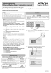
The SPARC CPU-5V addresses embedded applications where processing performance is as
important as VMEbus throughput. Based on FORCE COMPUTERS FGA-5000 VMEbus to
SBus interface gate array, the SPARC CPU-5V provides high speed VMEbus transfer
capabilities for standard transfers and extended 64-bit MBLT transfers. In addition, the SPARC
CPU-5V implements the capabilities of Sun Microsystems' SPARCstation 5 workstation on a
single-slot VMEbus board.
The SPARC CPU-5V is powerd by the microSPARC-II processor, which delivers a sustained
processing performance of 76 SPECint92 and 65 SPECfp92. The complete suite of I/O
functions includes fast SCSI-2, Ethernet, floppy disk, serial I/O, Centronics parallel I/O and
keyboard/mouse ports making the SPARC CPU-5V the ideal solution for computing and VME
transfer intensive embedded applications.
A complete 64-bit VMEbus interface and two standard SBus slots enable the expansion of I/O
memory and processing performance with a broad range of off-the-shelf solutions. The
software support for the SPARC CPU-5V ranges from Solaris, the most popular
implementation of the UNIX operating system on a RISC architecture, to sophisticated realtime operating systems such as VxWorks.
The SPARC CPU-5V is a single board computer combining workstation performance and
functionality with the ruggedness and expandability of an industry-standard single-slot
6U VMEbus board.
Page 2
FORCE COMPUTERS
SPARC CPU-5V Technical Reference Manual
FIGURE 1.
Introduction
Block Diagram of the SPARC CPU-5V
Keyboard/
Ethernet
SCSI-2
Serial I/O
Mouse
Rotary
Status
Switch
Display
Abort
Reset
16- or 64-Mbyte
Memory Expansion
Ethernet SIA
16- or 64-Mbyte
Boot
Memory Expansion
Flash Memory
NCR 89C105
NCR 89C100,
On-board DRAM
Flash Memory
Floppy, Key-
Centronics
16- or 64-MByte
2 MB User
Serial I/O,
Ethernet, SCSI,
board/Mouse
RTC/NVRAM
Centronics
microSPARC-II
Switch
IU/FPU/MMU/
Matrix
Cache
Floppy
SBus
FGA-5000
direct
SBus-to-VME64
SBus Slot
VMEbus P2
FORCE COMPUTERS
SBus Slot
Interface
VMEbus P1
Page 3
Introduction
1.3
SPARC CPU-5V Technical Reference Manual
Specifications
Below is a table outlining the specifications of the SPARC CPU-5V board.
Table 1: Specifications of the SPARC CPU-5V
Page 4
Processor
85, 100 or 110 MHz microSPARC-II
64.0 / 76 SPECint92
54.6 / 65 SPECfp92
Memory Management Unit
SPARC Reference MMU
Data/Instruction Cache
8 Kbyte/16 Kbyte
Main Memory
16-or 64-Mbyte base board DRAM,
expandable to 192 MB with mezzanine
modules
SBus Slots
2
SCSI-2 with DMA to SBus
10 Mbytes/sec fast SCSI-2
I/O on front panel and P2
Ethernet with DMA to SBus
10 Mbits/sec, AM7990 compatible
AUI port on front panel or P2
Parallel Port with DMA to SBus
3,4 Mbytes/sec
I/O on P2 via switch matrix
Floppy Disk Interface
250, 300, 500 Kbytes/sec and 1 Mbyte/sec
I/O on P2 via switch matrix
Serial I/O
2 RS-232 ports, RS-422/485 option via
hybrid modules,
I/O on front panel and P2
Keyboard/Mouse Port
Sun compatible, on front panel and P2
Counters/Timers
Two 22-bit, 500 ns resolution
Boot Flash Memory
512 Kbyte, on-board programmable
Hardware write protection
User Flash Memory
2 Mbytes, on-board programmable
Hardware write protection
RTC/NVRAM/Battery
M48T08
FORCE COMPUTERS
SPARC CPU-5V Technical Reference Manual
Introduction
Table 1: Specifications of the SPARC CPU-5V (Continued)
VMEbus Interface
64-bit master/slave
Master
A32, A24, A16
D64, D32, D16, D8
MBLT, BLT
Slave
A32, A24, A16
D64, D32, D16, D8
MBLT, BLT, UAT
Additional Features
Reset and Abort switches
Status LEDs, HEX display, Rotary switch,
Power-on reset circuitry, Voltage sensor
Firmware
OpenBoot with diagnostics
Power Consumption
(no SBus Modules installed)
+5V
+12V / -12V
Environmental Conditions
Temperature (Operating)
Temperature (Storage)
Humidity
0ο C to +55ο C
-40ο C to +85ο C
0% to 95% noncondensing
Board Size
FORCE COMPUTERS
5.0 A
0.7 / 0.2A
Single-Slot 6U form factor
160.00 x 233.35 mm
6.29 x 9.18 inches
Page 5
Introduction
SPARC CPU-5V Technical Reference Manual
1.3.1
Ordering Information
This next page contains a list of the product names and their descriptions.
Table 2: Ordering Information
Catalog Name
Product Description
CPU-5V/16-100-2
100 MHz microSPARC-II CPU board with 16-Mbyte base
board DRAM, 2-Mbyte User Flash Memory, SCSI, Ethernet,
floppy disk, parallel and 2 serial I/O ports, 64-bit VMEbus
interface, 2 SBus slots, OpenBoot firmware. Installation guide
included.
CPU-5V/64-100-2
as above, except 64-Mbyte base board DRAM.
CPU-5V/16-85-2
as above, except 85 MHz microSPARC-II and 16-Mbyte base
board DRAM.
CPU-5V/64-85-2
as above, except 64-Mbyte base board DRAM.
CPU-5V/16-110-2
as above, except 110 MHz microSPARC-II and 16-Mbyte base
board DRAM.
CPU-5V/64-110-2
as above, except 64-Mbyte base board DRAM.
MEM-5/16
16-Mbyte mezzanine memory module for use on the SPARC
CPU-5V. Up to two memory modules can be used.
MEM-5/64
64-Mbyte mezzanine memory module for use on the SPARC
CPU-5V. Up to two memory modules can be used.
SBus Modules
Page 6
SBus/GX
Color 2-D and 3-D wireframe accelerator 1152x900, 8 bits per
pixel, single SBus slot.
SBus/TGX
Color 2-D and 3-D wireframe high performance graphics accelerator up to 1152x900, 1-Mbyte VRAM, 8 bits per pixel, single
SBus slot.
SBus/TGX+
Color 2-D and 3-D wireframe high performance graphics accelerator up to 1600x1280, 4-Mbyte VRAM, 8 bits per pixel, double buffering, single SBus slot.
SBus/FP
6U front panel for up to 2 SBus cards.
FORCE COMPUTERS
SPARC CPU-5V Technical Reference Manual
Introduction
Table 2: Ordering Information (Continued)
Catalog Name
Product Description
Accessories
CPU-5V/TM
Technical Reference Manual Set for CPU-5V including OpenBoot User’s Manual and a detailed hardware description.
IOBP-10
I/O backpanel on VMEbus P2 with flat cable connectors for
Ethernet, SCSI, serial I/O and parallel/floppy disk interface for
use with the CPU-5V.
Serial-2CE
Serial adapter cable 26-pin micro D-Sub to 25-pin D-Sub for
use with the CPU-5V.
FH003/SET
Hybrid modules for RS-422 serial I/O configuration.
FH005/SET
Hybrid modules for RS-485 serial I/O configuration.
Software
Solaris 2.x/CPU-5V
Solaris 2.x package with Desktop Right-To-Use license, VMEbus driver on tape. Please contact your local sales representative for current version information.
Solaris 2.x/Client-RTU
Solaris 2.x Desktop Right-To-Use license. Without media.
Please contact your local sales representative for current version information.
Solaris 2.x/Server-RTU-up
Solaris 2.x Desktop to Workgroup Server Right-To-Use
upgrade license. Without media. Please contact your local sales
representative for current version information.
Solaris 2.x/UM
Solaris 2.x operating system user manual. Please contact your
local sales representative for current version information.
Solaris 1.x/CPU-5V
Solaris 1.x package with Right-To-Use license, VMEbus driver
on tape. Please contact your local sales representative for current version information.
Solaris 1.x/CPU-5V/RTU
Solaris 1.x Right-To-Use license. Without media. Please contact your local sales representative for current version information.
Solaris 1.x/CPU-5V/UURTU
Solaris 1.x multiuser Right-To-Use license. Without media.
Please contact your local sales representative for current version information.
Solaris 1.x/UM
Solaris 1.1 operating system user manual. Please contact your
local sales representative for current version information.
VxWorks/DEV SPARC products
VxWorks development package for SPARC host and target.
Please contact your local sales representative for current version information.
FORCE COMPUTERS
Page 7
Introduction
SPARC CPU-5V Technical Reference Manual
Table 2: Ordering Information (Continued)
Catalog Name
VxWorks/BSP CPU-5V
Page 8
Product Description
VxWorks board support package for CPU-5V. Please contact
your local sales representative for current version information.
FORCE COMPUTERS
SPARC CPU-5V Technical Reference Manual
1.4
Introduction
History of the Manual
Below is a description of the publication history of this SPARC CPU-5V Technical Reference
Manual.
Table 3: History of Manual
Edition No.
Description
Date
1
First Print
April 1995
2
microSPARC-II STP1012PGA-110 data sheet
added to Set of Data Sheets for the
June 1995
SPARC CPU-5V
3
The following corrections have been done:
the bit settings for the rotary switch on
page 89,
the commands led-display@ and leddisplay! on page 107,
the description of the commands
dma-mem>vme and dma-vme>mem on
page 145.
Chapter 4.7 "BusNet Support" has been added.
April 1996
4
Editorial changes have been made throughout.
The register names for USER LEDs 0 and 1
have been corrected.
December 1996
4.1
Section 4 and 5 have been exchanged
5.0
Chip-Level Adress Map of 89C105 completed
CPU-5V/16-100-2 and CPU-5V/64-100-2
implemented
FORCE COMPUTERS
August 1997
February 1998
Page 9
Introduction
Page 10
SPARC CPU-5V Technical Reference Manual
FORCE COMPUTERS
SPARC CPU-5V
Installation
SECTION 2
INSTALLATION
2.
Introduction
This Installation Section provides guidelines for powering up the SPARC CPU-5V board. The
Installation Section, which you have in your hand now, appears both as Section 2 of the SPARC
CPU-5V Technical Reference Manual and as a stand-alone Installation Guide. This standalone Installation Guide is delivered by FORCE COMPUTERS with every board. The SPARC
CPU-5V Technical Reference Manual provides a comprehensive hardware and software guide
to your board and is intended for those persons who require complete information.
2.1
Caution
Read the following safety note before
handling the board.
To ensure proper functioning of the product over its usual lifetime, take the following precautions before handling the board.
Electrostatic discharge and incorrect board installation and uninstallation can damage circuits
or shorten their lifetime.
• Before installing or uninstalling the board, read this Installation section.
• Before installing or uninstalling the board in a VME rack:
– Check all installed boards for steps that you have to take before turning off the power.
– Take those steps.
– Finally turn off the power.
• Before touching integrated circuits, ensure that you are working in an electrostatic free
environment.
• Ensure that the board is connected to the VMEbus via both connectors, the P1 and the P2
and that power is available on both.
• When operating the board in areas of strong electro-magnetic radiation, ensure that the
board
– is bolted on the VME rack
– and shielded by closed housing.
FORCE COMPUTERS
Page 11
Installation
2.2
SPARC CPU-5V
Location Diagram of the SPARC CPU-5V Board
A location diagram showing the important components on the top side of the CPU-5V appears
on the next page. On the page next to it, there is a location diagram showing the bottom side of
the CPU-5V. Both of these diagrams show only the components on the board which are of
interest to the user.
FIGURE 2.
Diagram of the CPU-5V (Top View)
MicroSPARC-II
Diagnostics
RTC/NVRAM
Abort
Upper
(#2)
Reset
Lower
(#1)
Boot Flash Memory
J22
J26
Rotary
Switch
J59 (Hybrid for Serial Port)
FGA-5000
SBus Slot 2
Serial Port
A and B
Memory Module # 1
Keyboard
and Mouse
Port
Memory Module # 2
Status LEDs
User LEDs
FORCE Gate Array - 5000
B3, B2, and B1
are the sockets for
Floppy / Parallel
Switch Matrix
LCA
SCSI
J60 (Hybrid for Serial Port)
NCR89C105
B11, B12, and B13
are the sockets for
Ethernet Switch
Matrix
Ethernet
SBus Slot 3
"SLAVIO"
B3 B2 B1
NCR89C100
"MACIO"
B11 B12 B13
Page 12
FORCE COMPUTERS
SPARC CPU-5V
Installation
FIGURE 3.
Diagram of the CPU-5V (Bottom View)
Switch 6
SCSI Term.
FrPl. dis.
SCSI Term.
P2 dis.
Write Boot
Flash
Write User
Flash
SW6
Switch 8
LCA Config.
Reserved
Slot 1 Fnct.
enabled
Power Sense
4.5/4.75 V
Reserved
SW8
Switch 5
TXC
Port B
SW7
CTS
Port B
SW5
RTS
Port B
Reserved
Switch 4
TXC
Port A
SW4
CTS
Port A
Switch 7
RESET SW
enabled
ABORT SW
enabled
SYSRESET
IN enabled
SYSRESET
OUT enabled
RTS
Port A
Reserved
FORCE COMPUTERS
Page 13
Installation
2.3
SPARC CPU-5V
Before Powering Up
Before powering up, please make sure that the default switch settings are all set according to
the table below. Check these switch settings before powering up the SPARC CPU-5V because
the board is configured for power up according to these default settings. For the position of the
switches on the board, please see “Diagram of the CPU-5V (Top View)” on page 12.
CAUTION: Switch off the power before installing the board into a VME rack.
2.3.1
Default Switch Settings
Table 4: Default Switch Settings
Diagram of Switch
with Default Setting
Switches
Default
Setting
Function
SWITCH 4 (Serial A Configuration)
SW4
1
Off 2
Off 3
Off 4
SW4-1
ON
On = SER_TRXCA to TXC_A_CONN (Pin 24)
Off = SER_RTS_A to TXC_A_CONN (Pin 24)
SW4-2
OFF
On = CTS_A_CONN (Pin 5) to SER_RTXCA and
Pullup to SER_CTSA
Off = RTXC_A_CONN (Pin 17) to SER_RTXCA and
CTS_A_CONN (Pin 5) to SER_CTSA
SW4-3
OFF
On = SER_TRXCA to RTS_A_CONN (Pin 4)
Off = SER_RTS_A to RTS_A_CONN (Pin 4)
SW4-4
OFF
RESERVED
On
SWITCH SW5 (Controls Serial Channel B)
SW5
1
2
Off
Off 3
Off 4
Page 14
SW5-1
ON
On = SER_TRXCB to TXC_B_CONN (Pin 25)
Off = SER_RTS_B to TXC_B_CONN (Pin 25)
SW5-2
OFF
On = CTS_B_CONN (Pin 13) to SER_RTXCB and
Pullup to SER_CTSB
Off = RTXC_B_CONN (Pin 22) to SER_RTXCB and
CTS_B_CONN (Pin 13) to SER_CTSB
SW5-3
OFF
On = SER_TRXCB to RTS_B_CONN (Pin 19)
Off = SER_RTS_B to RTS_B_CONN (Pin 19)
SW5-4
OFF
RESERVED
On
FORCE COMPUTERS
SPARC CPU-5V
Installation
Table 4: Default Switch Settings (Continued)
Diagram of Switch
with Default Setting
Switches
Default
Setting
Function
SWITCH 6
SW6
Off
Off
Off
Off
1
2
3
4
8
7
6
5
SW6-1
OFF
On = SCSI-Term Front Panel disabled
Off = SCSI-Term Front Panel automatic
SW6-2
OFF
On = SCSI-Term VME P2 disabled
Off = SCSI-Term VME P2 enabled
SW6-3
OFF
On = Write Boot Flash enabled
Off = Write Boot Flash disabled
SW6-4
OFF
On = Write User Flash enabled
Off = Write User Flash disabled
SWITCH 7
SW7
On
On
On
On
1
2
3
4
SW7-1
ON
On = RESET Switch enabled
Off = RESET Switch disabled
SW7-2
ON
On = ABORT Switch enabled
Off = ABORT Switch disabled
SW7-3
ON
On = VME_SYSRESET input enabled
Off = VME_SYSRESET input disabled
SW7-4
ON
On = VME_SYSRESET output enabled (See “VMEbus
SYSRESET Enable/Disable” on page 17)
Off = VME_SYSRESET output disabled
SWITCH 8
SW8-1
OFF
LCA Configuration Mode
On = Download (only for test purposes)
Off = Serial PROM
SW8-2
ON
On = VME Slot 1 Function enabled
Off = VME Slot 1 Function disabled
SW8
Off
Off
Off
1
2
3
4
FORCE COMPUTERS
On
Software must not enable or disable the VME Slot 1
Function in a way which contradicts with the switch setting. Take care not to change the value of bit 1 in the
Global Control and Status Register (GCSR) of the
FGA-5000. Please see the FGA-5000 Technical Reference Manual for further details.
(See “VMEbus SYSRESET Enable/Disable” on
page 17)
SW8-3
OFF
On = Power Sense 4.5V
Off = Power Sense 4.75V
SW8-4
OFF
Reserved
Page 15
Installation
2.4
SPARC CPU-5V
Powering Up
The initial power up can easily be done by connecting a terminal to ttya (serial port A). The
advantage of using a terminal is that no frame buffer, monitor, or keyboard is used for initial
power up, which facilitates a simple start up.
Please see the chapter “OpenBoot Firmware” on page 22 for more detailed information on
booting the system.
2.4.1
VME Slot-1 Device
The SPARC CPU-5V can be plugged into any VMEbus slot; however, the default
configuration sets the board as a VME slot-1 device, which functions as VME system
controller. To configure your CPU-5V in order that it is not a VME slot-1 device, the default
configuration must be changed so that SW8-2 is OFF. In that case, it would also be necessary
to change the SW7-4 to OFF, so that the VME_SYSRESET output is disabled.
CAUTION
Software must not enable or disable the VME Slot 1 Function in a way which contradicts with
the switch setting of SW8-2. Take care not to change the value of bit 1 in the Global Control
and Status Register (GCSR) of the FGA-5000. Please see the FGA-5000 Technical Reference
Manual for further details.
Before installing the SPARC CPU-5V in a miniforce chassis, please first disable the VMEbus
System Controller function by setting switch SW8-2 to OFF and also setting SW7-4 to OFF.
Page 16
FORCE COMPUTERS
SPARC CPU-5V
Installation
2.4.2
VMEbus SYSRESET Enable/Disable
2.4.2.1
SYSRESET Input
An external SYSRESET generates an on-board RESET in the default switch setting, i.e., SW73 is ON. When SW7-3 is OFF, the external SYSRESET does not generate an on-board RESET.
2.4.2.2
SYSRESET Output
An on-board RESET drives the SYSRESET signal to the VMEbus to low in the default switch
setting, i.e., SW7-4 is ON. When SW7-4 is OFF, an on-board RESET doesn’t drive the
SYSRESET signal to the VMEbus to low.
CAUTION
Do not switch SW7-4 (SYSRESET output) to ON and SW8-2 (VMEbus Slot-1 device) to OFF
at the same time.
The VMEbus Specification requires that if SYSRESET is driven, the SYSRESET signal shall
be driven low for at least 200 ms. However, when the CPU-5V is not a VMEbus slot-1 device
and the SYSRESET output signal is enabled, then the CPU-5V no longer conforms with this
rule.
By default, the SYSRESET output is enabled. In this case it generates the SYSRESET signal
to the VMEbus.
2.4.3
Serial Ports
By default, both serial ports are configured as RS-232 interfaces. It is also possible to
configure both ports as RS-422 or RS-485 interfaces. This optional configuration is achieved
with the special FORCE Hybrids FH-003 and FH-005.
The chapter “Default Switch Settings” on page 14 shows the necessary switch settings for
RS-232 operation, where SW4 controls serial port A and SW5 controls serial port B. Please
check that the switches are set accordingly.
FORCE COMPUTERS
Page 17
Installation
2.4.4
SPARC CPU-5V
RESET and ABORT Key Enable
To enable the RESET and the ABORT functions on the front panel, set switches SW7-1
(RESET) and SW7-2 (ABORT) to ON.
2.4.5
SCSI Termination
2.4.5.1
SCSI Termination at the Front Panel
Termination at the front panel for the SCSI interface is automatic when SW6-1 is OFF. This is
the default setting. Automatic means that when a SCSI cable is plugged into the front panel
connector, the termination is automatically disabled. When there is no SCSI cable plugged into
the front panel, then the termination is automatically enabled.
2.4.5.2
SCSI Termination at P2
Termination at the VMEbus P2 for the SCSI interface is enabled when SW6-2 is OFF. This is
the default setting.
Page 18
FORCE COMPUTERS
SPARC CPU-5V
2.4.6
Installation
Boot Flash Memory Write Protection
Both of the Boot Flash Memory devices are write protectable via the switch SW6-3. When
SW6-3 is OFF, the devices are write protected.
2.4.7
User Flash Memory Write Protection
The User Flash Memory devices are write protectable via SW6-4. When SW6-4 is OFF, the
User Flash Memory devices are write protected.
2.4.8
Reserved Switches
SW4-4, SW5-4, and SW8-4 are reserved for test purposes.
FORCE COMPUTERS
Page 19
Installation
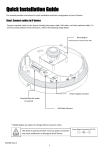
2.4.9
SPARC CPU-5V
Parallel Port or Floppy Interface via VME P2 Connector
Via a 16-pin configuration switch matrix, it is possible for either the parallel port interface or
the floppy interface to be available on the VME P2 connector.
The default setting enables the floppy interface via the VME P2 connector, with the
configuration switch matrix plugged into B1 and B2. This means, of course, that by default the
parallel port interface is not available via the VMEbus P2 connector.
To enable the parallel port interface via the VME P2 connector, plug the configuration switch
matrix in sockets B2 and B3.
FIGURE 4.
Floppy Interface Via VME P2 Connector
B3 B2 B1
CPU-5V Board
Page 20
FORCE COMPUTERS
SPARC CPU-5V
2.4.10
Installation
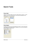
Ethernet via Front Panel or VME P2 Connector
Via an 8-pin configuration switch matrix, it is either possible for the Ethernet interface to be
available via the front panel or the VME P2 connector. The default configuration provides the
Ethernet through the front panel connector.
In order to have the Ethernet interface accessible via the VME P2 connector, the default
configuration must be changed.
By default, the Ethernet interface is available through the front panel with the configuration
switch matrix plugged into connectors B12 and B13.
To configure the Ethernet interface to be accessible from the VMEbus P2 connector, the
configuration switch matrix must be plugged into connectors B11 and B12.
FIGURE 5.
Ethernet Interface via Front Panel
B11 B12 B13
CPU-5V Board
WARNING: When the Ethernet interface is configured via VMEbus P2, do not connect
the Ethernet at the front panel.
FORCE COMPUTERS
Page 21
Installation
2.5
SPARC CPU-5V
OpenBoot Firmware
This chapter describes the use of OpenBoot firmware. Specifically, you will read how to
perform the following tasks.
•
•
•
•
•
Boot the System
Run Diagnostics
Display System Information
Reset the System
OpenBoot Help
For detailed information concerning OpenBoot, please see the OPEN BOOT PROM 2.0
MANUAL SET. This manual is included in the SPARC CPU-5V Technical Reference Manual
Set.
2.5.1
Boot the System
The most important function of OpenBoot firmware is booting the system. Booting is the
process of loading and executing a stand-alone program such as the operating system. After it
is powered on, the system usually boots automatically after it has passed the Power On SelfTest
(POST). This occurs without user intervention.
If necessary, you can explicitly initiate the boot process from the OpenBoot command
interpreter. Automatic booting uses the default boot device specified in non-volatile RAM
(NVRAM); user initiated booting uses either the default boot device or one specified by the
user.
To boot the system from the default boot device, type the following command at the Forth
Monitor prompt.
ok boot
or, if you are at the Restricted Monitor Prompt, you have to type the following:
>b
Page 22
FORCE COMPUTERS
SPARC CPU-5V
Installation
The boot command has the following format:
boot [device-specifier] [filename] [-ah]
The optional parameters are described as follows.
[device-specifier]
The name (full path or alias) of the boot device. Typical values
are cdrom, disk, floppy, net or tape.
[filename]
The name of the program to be booted. filename is relative to the
root of the selected device. If no filename is specified, the boot
command uses the value of boot-file NVRAM parameter. The
NVRAM parameters used for booting are described in the
following chapter.
[-a]
-a prompt interactively for the device and name of the boot file.
[-h]
-h halt after loading the program.
NOTE:
These options are specific to the operating system and may differ from system to system.
To explicitly boot from the internal disk, type:
ok boot disk
or at the Restricted Monitor prompt:
> b disk
FORCE COMPUTERS
Page 23
Installation
SPARC CPU-5V
To retrieve a list of all device alias definitions, type devalias at the Forth Monitor command
prompt. The following table lists some typical device aliases:
Table 5: Device Alias Definitions
Alias
Boot Path
Description
disk
/iommu/sbus/espdma/esp/sd@3,0
Default disk (1st internal) SCSI-ID 3
disk3
/iommu/sbus/espdma/esp/sd@3,0
First internal disk SCSI-ID 3
disk2
/iommu/sbus/espdma/esp/sd@2,0
Additional internal disk SCSI-ID 2
disk1
/iommu/sbus/espdma/esp/sd@1,0
External disk SCSI-ID 1
disk0
/iommu/sbus/espdma/esp/sd@0,0
External disk SCSI-ID 0
tape
/iommu/sbus/espdma/esp/st@4,0
First tape drive SCSI-ID 4
tape0
/iommu/sbus/espdma/esp/st@4,0
First tape drive SCSI-ID 4
tape1
/iommu/sbus/espdma/esp/st@5,0
Second tape drive SCSI-ID 5
cdrom
/iommu/sbus/espdma/esp/sd@6,0:d
CD-ROM partition d, SCSI-ID 6
net
/iommu/sbus/ledma/le
Ethernet
floppy
/obio/SUNW,fdtwo
Floppy drive
Page 24
FORCE COMPUTERS
SPARC CPU-5V
2.5.2
Installation
NVRAM Boot Parameters
The OpenBoot firmware holds configuration parameters in NVRAM. At the Forth Monitor
prompt, type printenv to see a list of all available configuration parameters. The OpenBoot
command setenv may be used to set these parameters.
setenv [configuration parameter] [value]
This information refers only to those configuration parameters which are involved in the boot
process. The following table lists these parameters.
Table 6: Setting Configuration Parameters
Parameter
Default Value
Description
auto-boot?
true
If true, boot automatically after power on or reset
boot-device
disk
Device from which to boot
boot-file
empty string
File to boot
diag-switch?
false
If true, run in diagnostic mode
diag-device
net
Device from which to boot in diagnostic mode
diag-file
empty string
File to boot in diagnostic mode
When booting an operating system or another stand-alone program, and neither a boot device
nor a filename is supplied, the boot command of the Forth Monitor takes the omitted values
from the NVRAM configuration parameters. If the parameter diag-switch? is false, boot-device
and boot-file are used. Otherwise, the OpenBoot firmware uses diag-device and diag-file for
booting.
For a detailed description of all NVRAM configuration parameters, please refer to the OPEN
BOOT PROM 2.0 MANUAL SET.
FORCE COMPUTERS
Page 25
Installation
2.5.3
SPARC CPU-5V
Diagnostics
At power on or after reset, the OpenBoot firmware executes POST. If the NVRAM
configuration parameter diag-switch? is true for each test, a message is displayed on a terminal
connected to the first serial port. In case the system is not working correctly, error messages
indicating the problem are displayed. After POST, the OpenBoot firmware boots an operating
system or enters the Forth Monitor if the NVRAM configuration parameter auto-boot? is false.
The Forth Monitor includes several diagnostic routines. These on-board tests let you check
devices such as network controller, SCSI devices, floppy disk system, memory, clock and
installed SBus cards. User installed devices can be tested if their firmware includes a selftest
routine.
The table below lists several diagnostic routines.
Page 26
FORCE COMPUTERS
SPARC CPU-5V
Installation
Table 7: Diagnostic Routines
Command
Description
probe-scsi
Identify devices connected to the on-board SCSI bus
probe-scsi-all [device-path]
Perform probe-scsi on all SCSI buses installed in the
system below the specified device tree node. (If
device-path is omitted, the root node is used.)
test device-specifier
Execute the specified device’s selftest method. devicespecifier may be a device path name or a device alias.
For example:
test net - test network connection
test /memory - test number of megabytes specified in
the selftest-#megs NVRAM parameter or test all of
memory if diag-switch? is true
test-all [device-specifier]
Test all devices (that have a built-in selftest method)
below the specified device tree node. (If device-path
is omitted, the root node is used.)
watch-clock
Monitor the clock function
watch-net
Monitor network connection
To check the on-board SCSI bus for connected devices, type:
ok probe-scsi
Target 3
Unit 0 Disk MICROP 1684-07MB1036511AS0C1684
ok
To test all the SCSI buses installed in the system, type:
ok probe-scsi-all
/iommu@0,10000000/sbus@0,10001000/esp@2,100000
Target 6
Unit 0 Disk Removable Read Only Device SONY CD-ROM CDU-8012 3.1a
/iommu@0,10000000/sbus@0,10001000/espdma@4,8400000/esp@4,8800000
Target 3
Unit 0 Disk MICROP 1684-07MB1036511AS0C1684
ok
The actual response depends on the devices on the SCSI buses.
FORCE COMPUTERS
Page 27
Installation
SPARC CPU-5V
To test a single installed device, type:
ok test device-specifier
This executes the device method name selftest of the specified device node.
device-specifier may be a device path name or a device alias as described in Table 5, “Device
Alias Definitions,” on page 24.The response depends on the selftest of the device node.
To test a group of installed devices, type:
ok test-all
All devices below the root node of the device tree are tested. The response depends on the
devices that have a selftest routine. If a device specifier option is supplied at the command line,
all devices below the specified device tree node are tested.
When you use the memory testing routine, the system tests the number of megabytes of
memory specified in the NVRAM configuration parameter selftest-#megs. If the NVRAM
configuration parameter diag-switch? is true, all memory is tested.
ok test /memory
testing 32 megs of memory at addr 0 27
ok
The command test-memory is equivalent to test /memory. In the example above, the first number (0)
is the base address of the memory bank to be tested, the second number (27) is the number of
megabytes remaining. If the CPU board is working correctly, the memory is erased and tested
and you will receive the ok prompt. If the PROM or the on-board memory is not working, you
receive one of a number of possible error messages indicating the problem.
To test the clock function, type:
ok watch-clock
Watching the ‘seconds’ register of the real time clock chip.
It should be ‘ticking’ once a second.
Type any key to stop.
22
ok
The system responds by incrementing a number once a second. Press any key to stop the test.
Page 28
FORCE COMPUTERS
SPARC CPU-5V
Installation
To monitor the network connection, type:
ok watch-net
Using AUI Ethernet Interface
Lance register test -- succeeded.
Internal loopback test -- succeeded.
External loopback test -- succeeded.
Looking for Ethernet packets.
‘.’ is a good packet. ‘X’ is a bad packet.
Type any key to stop.
...........X...........................X..............
ok
The system monitors the network traffic, displaying “.” each time it receives a valid packet and
displaying “X” each time it receives a packet with an error that can be detected by the network
hardware interface.
FORCE COMPUTERS
Page 29
Installation
2.5.4
SPARC CPU-5V
Display System Information
The Forth Monitor provides several commands to display system information. These
commands let you display the system banner, the Ethernet address for the Ethernet controller,
the contents of the ID PROM, and the version number of the OpenBoot firmware.
The ID PROM contains information specific to each individual machine, including the serial
number, date of manufacture, and assigned Ethernet address.
The following table lists these commands.
Page 30
FORCE COMPUTERS
SPARC CPU-5V
Installation
Table 8: Commands to Display System Information
Command
Description
banner
Display system banner.
show-sbus
Display list of installed and probed SBus
devices.
.enet-addr
Display current Ethernet address.
.idprom
Display ID PROM contents, formatted.
.traps
Display a list of SPARC trap types.
.version
Display version and date of the Boot PROM.
show-devs
Display a list of all device tree nodes.
devalias
Display a list of all device aliases.
FORCE COMPUTERS
Page 31
Installation
2.5.5
SPARC CPU-5V
Reset the System
If your system needs to be reset, you either press the reset button on the front panel or, if you
are in the Forth Monitor, type reset on the command line.
ok reset
The system immediately begins executing the Power On SelfTest (POST) and initialization
procedures. Once the POST finishes, the system either boots automatically or enters the Forth
Monitor, just as it would have done after a power-on cycle.
2.5.6
OpenBoot Help
The Forth Monitor contains an on-line help. To get this, type:
ok help
Enter ‘help command-name’ or ‘help category-name’ for more help
(Use ONLY the first word of a category description)
Examples: help select -or- help line
Main categories are:
File download and boot
Resume execution
Diag (diagnostic routines)
Power on reset
>-prompt
Floppy eject
Select I/O devices
Ethernet
System and boot configuration parameters
Line editor
Tools (memory,numbers,new commands,loops)
Assembly debugging (breakpoints,registers,disassembly,symbolic)
Sync (synchronize disk data)
Nvramrc (making new commands permanent)
ok
A list of all available help categories is displayed. These categories may also contain
subcategories. To get help for special forth words or subcategories just type help [name]. An
example is shown on the next page.
Page 32
FORCE COMPUTERS
SPARC CPU-5V
Installation
An example of how to get help for special forth words or subcategories:
ok help tools
Category: Tools (memory,numbers,new commands,loops)
Sub-categories are:
Memory access
Arithmetic
Radix (number base conversions)
Numeric output
Defining new commands
Repeated loops
ok
ok help memory
Category: Memory access
dump ( addr length -- ) display memory at addr for length bytes
fill ( addr length byte -- ) fill memory starting at addr with byte
move ( src dest length -- ) copy length bytes from src to dest address
map? ( vaddr -- ) show memory map information for the virtual address
l? ( addr -- ) display the 32-bit number from location addr
w? ( addr -- ) display the 16-bit number from location addr
c? ( addr -- ) display the 8-bit number from location addr
l@ ( addr -- n ) place on the stack the 32-bit data at location addr
w@ ( addr -- n ) place on the stack the 16-bit data at location addr
c@ ( addr -- n ) place on the stack the 8-bit data at location addr
l! ( n addr -- ) store the 32-bit value n at location addr
w! ( n addr -- ) store the 16-bit value n at location addr
c! ( n addr -- ) store the 8-bit value n at location addr
ok
The on-line help shows you the forth word, the parameter stack before and after execution of
the forth word ( before -- after), and a short description.
The on-line help of the Forth Monitor is located in the boot PROM, so there is not an online
help for all forth words.
FORCE COMPUTERS
Page 33
Installation
2.6
FIGURE 6.
SPARC CPU-5V
Front Panel
Diagram of the Front Panel
SPARC
CPU-5V
RESET
ABORT
D
I
A
G
M
O
D
E
RUN BM
0
1
K
B
D
S
E
R
I
A
L
A
+
B
S
C
S
I
E
T
H
E
R
N
E
T
Page 34
FORCE COMPUTERS
SPARC CPU-5V
2.6.1
Installation
Features of the Front Panel
The features listed below are described in detail in Section 3 of the SPARC CPU-5V Technical
Reference Manual.
Table 9: Front Panel Layout
Device
Function
Name
Switch
Reset
RESET
Switch
Abort
ABORT
HEX. Display
Diagnostic
DIAG
Rotary Switch
User defined
MODE
LED/LED
RUN/HALT
VME Busmaster/SYSFAIL
RUN
BM
LED/LED
Software programmable
01
Mini DIN Connector
Keyboard/Mouse
KBD
Serial Connector
Serial Interfaces
SERIAL A+B
SCSI Connector
SCSI Interface
SCSI
D-Sub Connector
Ethernet
ETHERNET
FORCE COMPUTERS
Page 35
Installation
SPARC CPU-5V
2.7
SPARC CPU-5V Connectors
The connectors on the SPARC CPU-5V are listed in the following table.
Table 10: SPARC CPU-5V Connectors
Function
Location
Type
Manufacturer Part
Number
Ethernet
Front Panel
15-pin D-Sub
AMP 747845-4
Serial Port A + B
Front Panel
26-pin Fine Pitch
AMP 749831-2
SCSI
Front Panel
50-pin Fine Pitch
AMP 749831-5
Keyboard/Mouse
Front Panel
8-pin Mini DIN
AMP 749232-1
SBus Slot2
(SBus Slave Select 1)
P3
96-pin SMD
FUJITSU FCN-234J096-G/V
SBus Slot3
(SBus Slave Select 2)
P4
96-pin SMD
FUJITSU FCN-234J096-G/V
VMEbus P1
P1
96-pin VGA
Various
VMEbus P2
P2
96-pin VGA
Various
The following pages show the pinouts of the connectors.
Page 36
FORCE COMPUTERS
SPARC CPU-5V
2.7.1
Installation
Ethernet Connector Pinout
The following table is a pinout of the Ethernet connector. The figure below shows the Ethernet
connector and pin numbers.
Table 11: Ethernet Connector Pinout
Pin
FIGURE 7.
Function
1
Analog GND
2
Collision+
3
Transmit Data+
4
Analog GND
5
Receive Data+
6
Analog GND
7
N.C.
8
Analog GND
9
Collision-
10
Transmit Data-
11
Analog GND
12
Receive Data-
13
+12VDC
14
Analog GND
15
N.C.
Pinout of the Ethernet Cable Connector
1
8
15
FORCE COMPUTERS
9
Page 37
Installation
2.7.2
SPARC CPU-5V
Serial Port A and B Connector Pinout
The following table is a pinout of the serial port connector. The figure on the next page shows
the serial port connector and location of the pin numbers.
Table 12: Serial Port A and B Connector Pinout
Pin
Signal
Direction
Port
Description
1
none
none
A
Not connected
2
TD
output
A
Transmit Data
3
RD
input
A
Receive Data
4
RTS
output
A
Request To Send
5
CTS
input
A
Clear To Send
6
DSR
input
A
Data Set Ready
7
SG
none
A
Signal Ground
8
DCD
input
A
Data Carrier Detect
9
none
none
Not connected
10
none
none
Not connected
11
SDTR
output
B
Secondary Data Terminal Ready
12
SDCD
input
B
Secondary Data Carrier Detect
13
SCTS
input
B
Secondary Clear To Send
14
STD
output
B
Secondary Transmit Data
15
TC
input
A
Transmit Clock: DCE source
16
SRD
input
B
Secondary Receive Data
17
RC
input
A
Receive Clock
18
STC
input
B
Secondary Transmit Clock
19
SRTS
output
B
Secondary Request To Send
20
DTR
output
A
Data Terminal Ready
21
SDSR
input
B
Secondary Data Terminal Ready*
22
SRC
input
B
Secondary Receive Clock*
23
SSG
none
B
Secondary Signal Ground
24
TC
output
A
Transmit Clock: DTE source
25
STC
output
B
Transmit Clock: DTE source
Page 38
FORCE COMPUTERS
SPARC CPU-5V
FIGURE 8.
Installation
Serial Ports A and B Connector Pinout
13
26
FORCE COMPUTERS
1
14
Page 39
Installation
2.7.3
SPARC CPU-5V
SCSI Connector Pinout
The following table is a pinout of the SCSI connector. The figure on the next page shows the
SCSI connector and location of the pin numbers.
Table 13: SCSI 50-Pin Connector
Page 40
Pin No.
Signal
Pin No.
Signal
1
GND
26
SCSI Data 0
2
GND
27
SCSI Data 1
3
GND
28
SCSI Data 2
4
GND
29
SCSI Data 3
5
GND
30
SCSI Data 4
6
GND
31
SCSI Data 5
7
GND
32
SCSI Data 6
8
GND
33
SCSI Data 7
9
GND
34
SCSI DP
10
GND
35
GND
11
GND
36
DISABLE
TERM
12
N.C.
37
N.C.
13
N.C.
38
TERMPWR
14
N.C.
39
N.C.
15
GND
40
GND
16
GND
41
SCSI ATN
17
GND
42
GND
18
GND
43
SCSI BSY
19
GND
44
SCSI ACK
20
GND
45
SCSI RST
21
GND
46
SCSI MSG
22
GND
47
SCSI SEL
23
GND
48
SCSI CD
24
GND
49
SCSI REQ
25
GND
50
SCSI IO
FORCE COMPUTERS
SPARC CPU-5V
FIGURE 9.
Installation
Pinout of SCSI Connector
25
50
FORCE COMPUTERS
1
26
Page 41
Installation
2.7.4
SPARC CPU-5V
Keyboard/Mouse Connector Pinout
The following table is a pinout of the keyboard/mouse connector.The keyboard and mouse
port is available on the front panel via a Mini DIN connector.
Table 14: Keyboard/Mouse Connector Pinout
Pin
FIGURE 10.
Function
1
GND
2
GND
3
+5VDC
4
Mouse In
5
Keyboard Out
6
Keyboard In
7
Mouse Out
8
+5VDC
Keyboard/Mouse Connector
8 7 6
5
4
2
Page 42
3
1
FORCE COMPUTERS
SPARC CPU-5V
2.7.5
Installation
VME P2 Connector Pinout
The following table is a pinout of the VME P2 connector.
Table 15: VME P2 Connector Pinout
PIN
Row A
Row C
Row C
(Floppy drive available via
switch matrix connected
to sockets B1 & B2)
(Parallel Port available via
switch matrix connected to
sockets B2 & B3)
1
SCSI Data 0
FLPY DENSEL
CENTR DS
2
SCSI Data 1
FLPY DENSENSE
CENTR D0
3
SCSI Data 2
CENTR D1
CENTR D1
4
SCSI Data 3
FLPY INDEX
CENTR D2
5
SCSI Data 4
FLPY DRVSEL
CENTR D3
6
SCSI Data 5
CENTR D4
CENTR D4
7
SCSI Data 6
CENTR D5
CENTR D5
8
SCSI Data 7
FLPY MOTEN
CENTR D6
9
SCSI DP
FLPY DIR
CENTR D7
10
GND
FLPY STEP
CENTR ACK
11
GND
FLPY WRDATA
CENTR BSY
12
GND
FLPY WRGATE
CENTR PE
13
TERMPWR
FLPY TRACK0
CENTR AF
14
GND
FLPY WRPROT
CENTR INIT
15
GND
FLPY RDDATA
CENTR ERR
16
SCSI ATN
FLPY HEADSEL
CENT SLCT IN
17
GND
FLPY DISKCHG
CENTR SLCT
18
SCSI BSY
FLPY EJECT
N.C.
19
SCSI ACK
ETH +12V
ETH +12V
20
SCSI RST
GND
GND
21
SCSI MSG
GND
22
SCSI SEL
23
SCSI CD
ETH REC+2)
ETH REC-2)
GND
ETH REC+2)
ETH REC-2)
24
SCSI REQ
25
SCSI IO
ETH TRA+2)
ETH TRA-2)
ETH TRA+2)
ETH TRA-2)
26
Mouse IN
27
Keyboard OUT
ETH COL+2)
ETH COL-2)
ETH COL+2)
ETH COL-2)
28
Keyboard IN
GND
GND
29
TXD Port A
TXD Port B
TXD Port B
30
RXD Port A
RXD Port B
RXD Port B
31
RTS Port A
RTS Port B
RTS Port B
32
CTS Port A
CTS Port B
CTS Port B
FORCE COMPUTERS
Page 43
Installation
2.7.6
SPARC CPU-5V
The IOBP-10 Connectors
The IOBP-10 is an I/O back panel on VMEbus P2 with flat cable connectors for SCSI, serial
I/O, Centronics/floppy interface, and a micro D-Sub connector for an Ethernet interface. This
back panel can be plugged into the VMEbus P2 connector. The diagram below shows all the
connectors. This IOBP-10 back panel is especially designed for the SPARC CPU-5V. Do not
use any other I/O back panels on the SPARC CPU-5V, for example, the IOBP-1.
FIGURE 11.
The IOBP-10
ABC
1
2
1
2
1
2
1
13
1
2
49
50
14
33
34
39
40
8 15
32
1
9
The pinouts of the connectors (P1) ... (P6) are shown in the following tables.
CAUTION
This IOBP-10 back panel is especially designed for the SPARC CPU-5V. Do not use any other
I/O back panels on the SPARC CPU-5V, for example, the IOBP-1.
Page 44
FORCE COMPUTERS
SPARC CPU-5V
Installation
Table 16: IOBP-10 P1 Pinout
ROW
A
Signal
ROW
B
Signal
ROW
C
Signal for
Floppy
Interface 1
Signal for
Parallel Port
Interface 1
1
SCSI Data 0
1
N.C.
1
FPY DENSEL
CENTR DS
2
SCSI Data 1
2
GND
2
FPY DENSENS
CENTR Data 0
3
SCSI Data 2
3
N.C..
3
N.C.
CENTR Data 1
4
SCSI Data 3
4
N.C.
4
FPY INDEX
CENTR Data 2
5
SCSI Data 4
5
N.C.
5
FPY DRVSEL
CENTR Data 3
6
SCSI Data 5
6
N.C.
6
N.C.
CENTR Data 4
7
SCSI Data 6
7
N.C.
7
N.C.
CENTR Data 5
8
SCSI Data 7
8
N.C.
8
FPY MOTEN
CENTR Data 6
9
SCSI DP
9
N.C.
9
FPY DIR
CENTR Data 7
10
GND
10
N.C.
10
FPY STEP
CENTR ACK
11
GND
11
N.C.
11
FPY WRDATA
CENTR BSY
12
GND
12
GND
12
FPY WRGATE
CENTR PE
13
TERMPWR
13
N.C.
13
FPY TRACK0
CENTR AF
14
GND
14
N.C.
14
FPY WRPROT
CENTR INIT
15
GND
15
N.C.
15
FPY RDDATA
CENTR ERR
16
SCSI ATN
16
N.C.
16
FPY HEADSEL
CENTR SLCT IN
17
GND
17
N.C.
17
FPY DISKCHG
CENTR SLCT
18
SCSI BSY
18
N.C.
18
FPY EJECT
RESERVED
19
SCSI ACK
19
N.C.
19
+12VDC 2
+12VDC 2
20
SCSI RST
20
N.C.
20
GND
GND
21
SCSI MSG
21
N.C.
21
GND
GND
22
SCSI SEL
22
GND
22
ETH REC+ 2
ETH REC+ 2
23
SCSI CD
23
N.C.
23
ETH REC- 2
ETH REC- 2
24
SCSI REQ
24
N.C.
24
ETH TRA+ 2
ETH TRA+ 2
25
SCSI IO
25
N.C.
25
ETH TRA- 2
ETH TRA- 2
26
Mouse IN
26
N.C.
26
ETH COL+ 2
ETH COL+ 2
FORCE COMPUTERS
Page 45
Installation
SPARC CPU-5V
Table 16: IOBP-10 P1 Pinout (Continued)
ROW
A
Signal
ROW
B
Signal
ROW
C
Signal for
Floppy
Interface 1
Signal for
Parallel Port
Interface 1
27
Keyboard
Out
27
N.C.
27
ETH COL- 2
ETH COL- 2
28
Keyboard In
28
N.C.
28
GND
GND
29
TxD Port A
29
N.C.
29
TxD Port B
TxD Port B
30
RxD Port A
30
N.C.
30
RxD Port B
RxD Port B
31
RTS Port A
31
GND
31
RTS Port B
RTS Port B
32
CTS Port A
32
N.C.
32
CTS Port B
CTS Port B
1) For further information, see “Floppy Interface Via VME P2 Connector” on page 20
2) For further information, please see “Ethernet Interface via Front Panel” on page 21
Page 46
FORCE COMPUTERS
SPARC CPU-5V
Installation
Table 17: IOBP-10 P2 Pinout (SCSI)
FORCE COMPUTERS
Pin
No.
Signal
Pin
No.
1
GND
2
SCSI Data 0
3
GND
4
SCSI Data 1
5
GND
6
SCSI Data 2
7
GND
8
SCSI Data 3
9
GND
10
SCSI Data 4
11
GND
12
SCSI Data 5
13
GND
14
SCSI Data 6
15
GND
16
SCSI Data 7
17
GND
18
SCSI DP
19
GND
20
GND
21
GND
22
GND
23
GND
24
GND
25
N.C.
26
TERMPWR
27
GND
28
GND
29
GND
30
GND
31
GND
32
SCSI ATN
33
GND
34
GND
35
GND
36
SCSI BSY
37
GND
38
SCSI ACK
39
GND
40
SCSI RST
41
GND
42
SCSI MSG
43
GND
44
SCSI SEL
45
GND
46
SCSI CD
47
GND
48
SCSI REQ
49
GND
50
SCSI IO
Signal
Page 47
Installation
SPARC CPU-5V
Table 18: IOBP-10 P3 Pinout (Floppy)
Page 48
Pin
No.
Signal
Pin
No.
1
FPY EJECT
2
FPY DENSEL
3
GND
4
FPY DENSENS
5
GND
6
N.C.
7
GND
8
FPY INDEX
9
GND
10
FPY DRVSEL
11
GND
12
N.C.
13
GND
14
N.C.
15
GND
16
FPY MOTEN
17
GND
18
FPY DIR
19
GND
20
FPY STEP
21
GND
22
FPY WRDATA
23
GND
24
FPY WRGATE
25
GND
26
FPY TRACK0
27
N.C.
28
FPY WRPROT
29
GND
30
FPY RDDATA
31
GND
32
FPY HEADSEL
33
GND
34
FPY DISKCHG
Signal
FORCE COMPUTERS
SPARC CPU-5V
Installation
Table 19: IOBP-10 P4 Pinout (Centronics)
Pin
No.
FORCE COMPUTERS
Signal
Pin
No.
Signal
1
CENTR DS
2
GND
3
CENTR Data 0
4
GND
5
CENTR Data 1
6
GND
7
CENTR Data 2
8
GND
9
CENTR Data 3
10
GND
11
CENTR Data 4
12
GND
13
CENTR Data 5
14
GND
15
CENTR Data 6
16
GND
17
CENTR Data 7
18
GND
19
CENTR ACK
20
GND
21
CENTR BSY
22
GND
23
CENTR PE
24
GND
25
CENTR SLCT
26
CENTR INIT
27
CENTR AF
28
CENTR ERR
29
N.C.
30
GND
31
GND
32
N.C.
33
N.C.
34
N.C.
35
N.C.
36
CENTR SLCT IN
37
N.C.
38
N.C.
39
N.C.
40
N.C.
Page 49
Installation
SPARC CPU-5V
Table 20: IOBP-10 P5 Pinout (Serial)
Pin
No.
Pin
No.
Signal
Signal
1
GND
2
Keyboard In
3
Mouse In
4
Keyboard Out
5
TxD Port B
6
TxD Port A
7
RxD Port B
8
RxD Port A
9
RTS Port B
10
RTS Port A
11
CTS Port B
12
CTS Port A
13
GND
14
GND
Table 21: IOBP-10 P6 Pinout (Ethernet)
Pin
Page 50
Function
1
GND
2
Collision+
3
Transmit Data+
4
GND
5
Receive Data+
6
GND
7
N.C.
8
N.C.
9
Collision-
10
Transmit Data-
11
GND
12
Receive Data-
13
+12VDC
14
GND
15
N.C.
FORCE COMPUTERS
SPARC CPU-5V
2.8
Installation
Ethernet Address and Host ID
This section explains how to determine the SPARC/CPU-5V Ethernet address and its host ID.
The 48-bit (6-byte) Ethernet Address
Byte
5
0
4
0
47
8
40
39
3
0
4
32
31
2
2
0
24
23
These 3 byte always remain
0016:8016:4216
1
B
X
16
0
X
15
X
8
Specific Machine:
0B16 for SPARC/
CPU-5V
X
7
0
These 2 byte are
consecutively
numbered.
The 32-bit (4-byte) host ID
Byte
2
3
7
32
2
Y
25
These 8 bit identify
the architecture type.
FORCE COMPUTERS
24
0
1
Y
16
Y
15
Y
Y
8
7
Y
0
The least significant 24 bit contain the
sum of 8B.400016 and the rightmost
2 byte of the board’s Ethernet address.
Page 51
Installation
Page 52
SPARC CPU-5V
FORCE COMPUTERS
SPARC CPU-5V Technical Reference Manual
SECTION 3
3.
Hardware Description
HARDWARE DESCRIPTION
Overview
Based on FORCE COMPUTERS FGA-5000 VMEbus to SBus interface gate array, the SPARC
CPU-5V provides high speed VMEbus transfer capabilities for standard transfers and extended
64-bit MBLT transfers. In addition, the SPARC CPU-5V implements the capabilities of Sun
Microsystems' SPARCstation 5 workstation on a single-slot VMEbus board.
The SPARC CPU-5V is powered by the microSPARC-II processor, which delivers a sustained
processing performance of 76 SPECint92 and 65 SPECfp92. The complete suite of I/O
functions includes fast SCSI-2, Ethernet, floppy disk, serial I/O, Centronics parallel I/O and
keyboard/mouse ports making the SPARC CPU-5V the ideal solution for computing and VME
transfer intensive embedded applications.
A complete 64-bit VMEbus interface and two standard SBus slots enable the expansion of I/O
memory and processing performance with a broad range of off-the-shelf solutions. The
software support for the SPARC CPU-5V ranges from Solaris, the most popular
implementation of the UNIX operating system on a RISC architecture, to sophisticated realtime operating systems such as VxWorks.
The SPARC CPU-5V is a single board computer combining workstation performance and
functionality with the ruggedness and expandability of an industry-standard single-slot
6U VMEbus board.
3.1
Block Diagram
A block diagram showing a functional overview of the CPU-5V is shown on the next page.
FORCE COMPUTERS
Page 53
Hardware Description
SPARC CPU-5V Technical Reference Manual
FIGURE 12.
Block Diagram of the SPARC CPU-5V
Keyboard/
Ethernet
SCSI-2
Serial I/O
Mouse
Rotary
Status
Switch
Display
Abort
Reset
16 or 64 Mbyte
Memory Expansion
Ethernet SIA
16 or 64 Mbyte
Boot
Memory Expansion
FLASH MEMORY
NCR 89C105
NCR 89C100,
Serial I/O,
Ethernet, SCSI,
Floppy, Key-
Centronics
16 or 64 Mbyte
2 MB User
On-board DRAM
FLASH MEMORY
board/Mouse
RTC/NVRAM
Centronics
microSPARC-II
Switch
Matrix
IU/FPU/MMU/
Cache
Floppy
SBus
FGA-5000
direct
SBus-to-VME64
SBus Slot
VMEbus P2
Page 54
SBus Slot
Interface
VMEbus P1
FORCE COMPUTERS
SPARC CPU-5V Technical Reference Manual
3.2
Hardware Description
The microSPARC-II Processor
The microSPARC-II CPU chip is at the core of the SPARC CPU-5V. This chip is realized in a
321-pin CPGA package. A Floating Point Unit, an Integer Unit, an MMU, an Instruction
Cache, and a Data Cache are integrated in the microSPARC-II processor. Please see the
microSPARC-II User’s Manual (STP1012PGA) for further information.
3.2.1
Features of the microSPARC-II Processor
• microSPARC-II chip running at 85 MHz, 100 MHz or 110 MHz
• Integer Unit with 5-stage pipeline
• Floating Point Unit
• SPARC Reference Memory Management Unit
• A 16 Kbyte instruction cache and an 8 Kbyte data cache, directly mapped
• Memory interface which supports up to 256 Mbyte DRAM
• SBus controller supports up to five SBus slots plus one "master-only" slot
FORCE COMPUTERS
Page 55
Hardware Description
3.2.2
SPARC CPU-5V Technical Reference Manual
Address Mapping for microSPARC-II
The table below lists the physical addresses of the microSPARC-II processor.
Table 22: Physical Memory Map of microSPARC-II
Address
Function
0000 0000 ->
0FFF FFFF
User Memory
1000 0000 ->
1FFF FFFF
Control Space
2000 0000 ->
2FFF FFFF
AFX Frame buffer
SBus Slot #
Select #
SBus Slot 0
3000 0000 ->
3FFF FFFF
SBus Slot 1
SBus Slave Select 0
4000 0000 ->
4FFF FFFF
SBus Slot 2
SBus Slave Select 1
5000 0000 ->
5FFF FFFF
SBus Slot 3
SBus Slave Select 2
6000 0000 ->
6FFF FFFF
SBus Slot 4
SBus Slave Select 3
7000 0000 ->
7FFF FFFF
SBus Slot 5
SBus Slave Select 4
Page 56
FORCE COMPUTERS
SPARC CPU-5V Technical Reference Manual
3.3
Hardware Description
The Shared Memory
The microSPARC-II chip interfaces directly to a 64-bit wide DRAM on one side and to the
SBus on the other side. The shared DRAM is 64-bit wide with one parity bit for 32-bit data.
The SPARC CPU-5V provides 16- or 64-Mbyte DRAM which is assembled on the board itself.
There are 4-Mbit devices used to realize 16 Mbytes and there are 16-Mbit devices to realize 64
Mbytes.
The microSPARC-II chip supports up to eight memory banks (bank 0 to bank 7). Two of the
eight memory banks are used on the SPARC CPU-5V base board (bank 0 and bank 1). The
signals for the remaining memory banks are routed to the memory module connectors for
module #1 and module #2.
Memory connector for memory module #1 supports banks 2, 3, 4 and 5. Memory connector for
memory module #2 supports banks 4, 5, 6 and 7. Memory modules with up to 4 memory banks
can be used. As shown in the table below, the memory bank structure is organized so that
memory modules with a bank count from 1 to 4 (if available) can be used in any combination.
Each module has up to 4 banks, only up to 8 banks in total are allowed. A memory module can
contain bank A, or banks A and B, or banks A, B and C, or bank A, B, C and D.
Table 23: Bank Selection
Bank
Select
from
Processor
Base-board
Bank A
0
x
Module on Connector #1
Bank B
1
2
3
4
5
Bank A
Bank B
Bank C
Module on Connector #2
Bank D
Bank A
Bank C
Bank D
x
x
x
x
x
x
x
6
7
Bank B
x
x
The shaded area above shows an example of how the banks are selected by the processor. In
other words, the processor can select Bank B of the module on connector #1 by its own bank
select 3. CAUTION: Do not connect more than one physical memory bank to one bank select
from the processor. In other words, you can connect either bank C of the module on connector
# 1, or bank D of module on connector # 2 to bank select 4, or you can connect either bank D
of the module on connector # 1, or bank C of the module on connector # 2 to bank select 5.
FORCE COMPUTERS
Page 57
Hardware Description
SPARC CPU-5V Technical Reference Manual
The table below shows the base board memory capacity and the memory banks used by the
microSPARC-II.
Table 24: CPU-5V Memory Banks
3.4
CPU-5V
Memory
Capacity
Memory Banks
0 and 1 are Used
16 Mbytes
X
64 Mbytes
X
Memory Module MEM-5
It is possible to upgrade your CPU-5V board with one or two memory modules (the remaining
banks 2 to 7). The memory modules are available in different variants.
The MEM-5 provides 16- or 64-Mbyte DRAM. There are 4-Mbit devices used to realize 16
Mbytes and there are 16-Mbit devices to realize 64 Mbytes.
The table below shows the board memory capacity and the memory banks used on the
microSPARC-II.
To understand the structure of the memory make sure you read “The Shared Memory” on
page 57.
Table 25: MEM-5 Memory Banks
MEM-5
Memory
Capacity
Memory Banks
A and B are Used
16 Mbytes
X
64 Mbytes
X
Installing the memory modules is described in the document "How to Install MEM-5."
Page 58
FORCE COMPUTERS
SPARC CPU-5V Technical Reference Manual
3.5
Hardware Description
SBus Participants
There are two SBus slots located on the component side of the board. SBus Slot # 2 is located
at connector P3 and SBus Slot # 3 is located at connector P4. A diagram of the board is located
in the figure “Diagram of the CPU-5V (Top View)” on page 12.
The microSPARC-II chip supports up to 5 SBus slots plus an additional "master-only" slot. The
SBus controller is inside the microSPARC-II chip.
The following table shows the microSPARC-II physical address map including all of its SBus
slots and their functions on the SPARC CPU-5V.
3.5.1
Address Mapping for SBus Slots on the SPARC CPU-5V
Table 26: Physical Memory Map of SBus on SPARC CPU-5V
Address
Function
SBus Slot #
Select #
2000 0000 ->
2FFF FFFF
AFX Frame buffer
SBus Slot 0
3000 0000 ->
3FFF FFFF
VMEbus Interface
SBus Slot 1
SBus Slave Select 0
4000 0000 ->
4FFF FFFF
SBus Module P3
VMEbus Interface
SBus Slot 2
SBus Slave Select 1
5000 0000 ->
5FFF FFFF
SBus Module P4
VMEbus Interface
SBus Slot 3
SBus Slave Select 2
6000 0000 ->
6FFF FFFF
VMEbus Interface
SBus Slot 4
SBus Slave Select 3
7000 0000 ->
77FF FFFF
NCR89C105 (SLAVIO)
chip
SBus Slot 5
SBus Slave Select 4
7800 0000 ->
7DFF FFFF
NCR89C100 (MACIO)
chip
SBus Slot 5
SBus Slave Select 4
7E00 0000 ->
7FFF FFFF
VMEbus Interface
SBus Slot 5
SBus Slave Select 4
If there are no SBus modules installed, SBus Slot 1, 2, 3 and 4, together with SBus Slot 5
address range: 7E00 0000-7FFF FFFF, are available for the VMEbus Interface.
FORCE COMPUTERS
Page 59
Hardware Description
3.6
SPARC CPU-5V Technical Reference Manual
NCR89C100 (MACIO)
The NCR89C100 is located on SBus Slave Select 4 at physical address $7800 0000. This chip
drives the SCSI, Ethernet and Centronics parallel port.
The NCR89C100 SBus master integrates high performance I/O macrocells and logic including
an Ethernet controller core, a fast 53C9X SCSI core, a high-speed parallel port, a DMA2
controller and an SBus interface.
The Ethernet core is compatible with the industry standard 7990 Ethernet controller. The SCSI
core is a superset of the industry standard NCR53C90A which has been modified to support
fast SCSI. The uni/bi-directional parallel port is Centronics compliant and can operate in either
programmed I/O or DMA mode.
The DMA2 block comprises the logic used to interface each of these functions to the SBus. It
provides buffering for each of the functions. Buffering takes the form of a 64-byte data cache
and 16-bit wide buffer for the Ethernet channel, and a 64-byte FIFO for both the SCSI channel
and the parallel port. The DMA2 incorporates as improved cache and FIFO draining algorithm
which allows better SBus utilization than previous DMA implementations.
Page 60
FORCE COMPUTERS
SPARC CPU-5V Technical Reference Manual
3.6.1
Hardware Description
Features of the NCR89C100 on the SPARC CPU-5V
• Fast 8-bit SCSI
• Supports fast SCSI mode
• Backward compatible to 53C90A
• 7990-compatible Ethernet
• Parallel Port
• I/O or DMA programmable modes
• Centronics compatibility
• LS64854-compatible DMA2 Controller
• Glueless SBus Interface clocked with 21.25 MHz @ 85 MHz processor frequency
• Glueless SBus Interface clocked with 22.00 MHz @ 110 MHz processor frequency
• Glueless SBus Interface clocked with 25.00 MHz @ 100 MHz processor frequency
• Concurrently supports:
• 10 MB/sec SCSI transfers
• 3.4 MB/sec Parallel port transfers
• 1.25 MB/sec Ethernet transfers
• 64-byte FIFO for SCSI and Parallel Port data
• Supports SBus burst modes
• 4-word, 8-word and “no/burst”
• Packaged in 160-pin PQFP
For further information about the NCR89100, please see NCR SBus I/O Chipset Data Manual.
FORCE COMPUTERS
Page 61
Hardware Description
3.6.2
SPARC CPU-5V Technical Reference Manual
SCSI
The SCSI interface provides a standard interface to a wide variety of mass storage devices, such
as hard disks, tapes and CD-ROMs. The SCSI transfers up to 10 Mbytes per second.
The SPARC CPU-5V board’s SCSI is realized via the NCR89C100. The NCR89C100 has onchip 48 mA drivers and therefore provides direct drive of single-ended SCSI bus. The SCSI
core is a superset of the industry standard NCR53C90A which has been modified to support
fast SCSI.
The SCSI interface is single ended and supports “TERMPWR”. The NCR89C100 DMA2 core
is able to transfer the data to and from the shared main memory.
All signals of the SCSI interface are routed to a standard connector on the front panel and to
the VME P2 connector. This 2nd connection is compatible to the CPU-2CE, CPU-3CE and the
CPU-5CE. Please see the “VME P2 Connector Pinout” on page 43 where the SCSI signals on
the VME P2 connector are shown.
3.6.3
SCSI Termination
When only one of the SCSI connectors is used, the other one is an end point. In that case, the
SCSI bus must be terminated near the unused connector. This is supported on the CPU-5V
board through one termination at the front panel and one termination at VME P2.
The front panel termination of the SCSI can be configured via the on-board switch SW6-1. If
SW6-1 is ON, the front panel termination is disabled. If SW6-1 is OFF, the termination is
automatic. Automatic means that when a SCSI cable is plugged into the front panel connector,
the termination is automatically disabled. When there is no SCSI cable plugged into the front
panel, the termination is automatically enabled.
The VME P2 termination of the SCSI interface can be enabled or disabled via the switch
SW6-2. If SW6-2 is OFF, the termination is enabled. If SW6-2 is ON, the termination is
disabled.
Please see “Diagram of the CPU-5V (Top View)” on page 12 for the location of the switches
on the board.
CAUTION
When installing the SPARC CPU-5V in a MICROFORCE chassis, please first disable the SCSI
termination by switching SW6-1 and SW6-2 to ON.
Page 62
FORCE COMPUTERS
SPARC CPU-5V Technical Reference Manual
3.6.4
Hardware Description
Ethernet
The NCR89C100 DMA controller enables the Ethernet interface to transfer data to and from
the shared main memory. The Ethernet core is register level compatible with the AMD
Am7990, Revision F, standard Ethernet controller, which is capable of transferring Ethernet
data up to 10 Mbit/sec.
An 8-pin configuration switch matrix selects whether the Ethernet interface is available via the
front panel or the VME P2 connector. By default, the Ethernet Interface is available through
the front panel connector with the I/O bridge plugged into connectors B12 and B13.
It is possible to have the Ethernet interface accessible on the VME P2 connector by changing
the default configuration. In order that the Ethernet interface is accessible from the VMEbus P2
connector, the I/O bridge array must be plugged into connectors B11 and B12.
Please see the figure “Ethernet Interface via Front Panel” on page 21 for information about
changing the Ethernet configuration.
CAUTION
When the Ethernet is configured via P2, do not connect the Ethernet at the front panel.
3.6.5
Parallel Port
The parallel port is centronics compliant and provides uni/bi-directional communication. It
operates in either programmed I/O or DMA mode.
The default configuration enables the floppy interface via the VME P2 connector, with the
configuration switch matrix plugged into B1 and B2. This means, of course, that by default the
parallel port interface is not available via the VMEbus P2 connector. It is the floppy disk
interface which is available on the VMEbus P2 connector by default.
In order to configure the parallel port to be accessible from the VMEbus P2 connector, the
switch matrix must be plugged into connectors B2 and B3. Please see the figure “Floppy
Interface Via VME P2 Connector” on page 20 for information about changing the
configuration.
FORCE COMPUTERS
Page 63
Hardware Description
3.7
SPARC CPU-5V Technical Reference Manual
NCR89C105 (SLAVIO)
The NCR89C105 SBus slave integrates most of the 8-bit system I/O functions including two
dual channel 8530-compatible serial controllers, a high speed 8277AA-1-compatible floppy
disk controller, counter/timers, interrupt controllers, and system reset logic. It also provides an
SBus interface for several other byte-wide peripherals through an external expansion bus.
The primary serial controller is 8530-compatible and can be used as two general purpose serial
ports.
The second serial controller is subset of the 8530 standard and is dedicated for the keyboard/
mouse connection.
The 8277AA-1-compatible floppy disk controller supports up to 1 Mbit/sec data transfer rate.
To reduce part count and system cost, a glueless interface to the SBus is provided. The slave
I/O also includes an 8-bit expansion bus with control to support RTC/NVRAM, EPROM and
generic 8-bit devices externally.
3.7.1
Features of the NCR89C105 on the SPARC CPU-5V
• Dual-channel serial ports (8530-compatible)
• Keyboard/ mouse port
• 82077AA-1 floppy disk controller
• 8-bit expansion bus for Flash Memory/TOD/NVRAM
• Glueless SBus interface clocked with 21.25 MHz @ 85 MHz, 22.0 MHz @ 110 MHz or
25.00 MHz @ 100 MHz processor frequency
• Interrupt controller
• System reset control
• Programmable 22-bit counters & timers
• Auxiliary I/O registers
• Packaged in 160-pin PQFP
For further information about the NCR89100, please refer to the NCR SBus I/O Chipset Data
Manual.
Page 64
FORCE COMPUTERS
SPARC CPU-5V Technical Reference Manual
3.7.2
Hardware Description
Address Map of Local I/O Devices on SPARC CPU-5V
The following table lists the physical addresses for all local I/O devices and the accesses
permitted ((B)yte, (H)alf Word, (W)ord) and (D)ouble Word.
Table 27: NCR89C105 Chip Address Map
Physical
Address
Device
Access
7000 0000 ->
70FF FFFF
Boot Flash Memory and User Flash Memory
B,H,W
7100 0000 ->
711F FFFF
Keyboard, Mouse, and Serial Ports
B
7100 0000
7100 0002
7100 0004
7100 0006
7110 0000
7110 0002
7110 0004
7110 0006
Mouse Control Port
Mouse Data Port
Keyboard Control Port
Keyboard Data Port
TTYB Control Port
TTYB Data Port
TTYA Control Port
TTYA DATA Port
7120 0000 ->
712F FFFF
RTC/NVRAM
B,H,W
7130 0000 ->
7137 FFFF
Boot Flash Memory and User Flash Memory Programming
B
7138 0000 ->
713F FFFF
Additional Registers
B
7140 0000 ->
714F FFFF
Floppy Controller
B
7140 0002
7140 0004
7140 0004
7140 0005
7140 0006
7140 0007
7140 0007
Digital Output Register (DOR)
Main Status Register (MSR, Read Only)
Datarate Select Register (DSR, Write Only)
FIFO
Reserved (Test mode select)
Digital Input Register (DIR, Read Only)
Configuration Control Register (CCR, Write Only)
7150 0000 ->
7170 0000
Reserved
7180 0000
89C105 Configuration Register
B
7190 0000 ->
719F FFFF
Auxiliary I/O Registers
B
7190 0000
Aux 1 Register (Miscellaneous System Functions)
7191 0000
Aux 2 Register (Software Powerdown Control)
FORCE COMPUTERS
Page 65
Hardware Description
SPARC CPU-5V Technical Reference Manual
Table 27: NCR89C105 Chip Address Map
Physical
Address
Page 66
Device
Access
71A0 0000
Diagnostic Message Register
B
71B0 0000
Modem Register
B
71C0 0000 ->
71CF FFFF
Reserved
71D0 0000 ->
71DF FFFF
Counter/Timer
71D0 0000
71D0 0004
71D0 0008
71D0 000C
71D1 0000
71D1 0004
71D1 0008
71D1 000C
71D1 0010
Processor Counter Limit Register or User Timer MSW
Processor Counter Register or User Timer LSW
Processor Counter Limit Register (non-resetting port)
Processor Counter User Timer Start/Stop Register
System Limit Register (Level 10 Interrupt)
System Counter Register
System Limit Register (non-resetting port)
Reserved
Timer Configuration Register
71E0 0000 ->
71EF FFFF
Interrupt Controller
71E0 0000
71E0 0004
71E0 0008
71E1 0000
71E1 0004
71E1 0008
71E1 000C
71E1 0010
Processor Interrupt Pending Register
Processor Processor Clear-Pending Pseudo-Register
Processor Set-Soft-Interrupt Pseudo-Register
System Interrupt Pending Register
Interrupt Target Mask Register
Interrupt Target Mask Clear Pseudo-Register
Interrupt Target Mask Set Pseudo-Register
Interrupt Target Register (Reads as 0, Write has no effect)
71F0 0000
System Control / Status Register
W,D
W
W
FORCE COMPUTERS
SPARC CPU-5V Technical Reference Manual
3.7.3
Hardware Description
Serial I/O Ports
The two serial I/O ports are available on the front panel via one 26-pin shielded connector .
Both of the two ports are available via the VMEbus P2 connector (RS-232 only), each with four
signals (RXD, TXD, RTS, CTS). Each of the two serial I/O ports are independent full-duplex
ports.
The 8530 SCC block is functionally compatible with the standard NMOS 8530 and therefore
provides two fully independent full-duplex ports.
The physical address map for the serial ports is shown in “NCR89C105 Chip Address Map” on
page 65.
3.7.4
RS-232, RS-422 or RS-485 Configuration
Both serial ports can be configured as RS-232, RS-422 or RS-485. By default, the FH-002
hybrid module is installed for RS-232 operation.
In order to simplify changing the serial interfaces, FORCE COMPUTERS has developed
RS-232, RS-422 and RS-485 hybrid modules: the FH-002, FH-003 and FH-005. These 21-pin
SIL modules are installed in sockets so that they may be easily changed to meet specific
application needs.
To change the configuration of serial port A, insert the respective hybrid in socket J59. To
change the configuration of serial port B, insert the respective hybrid in socket J60. For the
position of the sockets on the board, please see “Diagram of the CPU-5V (Top View)” on
page 12.
Table 28: RS-232, RS-422 or RS-485 Configuration
Hybrid
Configuration
Socket for
Serial Port A
Socket for
Serial Port B
Default
FH-002
RS-232
J59
J60
*
FH-003
RS-422
J59
J60
FH-005
RS-485
J59
J60
FORCE COMPUTERS
Page 67
Hardware Description
3.7.5
SPARC CPU-5V Technical Reference Manual
RS-232 Hardware Configuration
The serial ports A and B are configured by default for RS-232 operation. The following
individual I/O signals are available for serial ports A and B on the front panel connector.
Table 29: Serial Ports A and B Pinout List (RS-232)
Pin
Transmitted Signals
Pin
Received Signals
2
14
TXD-Transmit Data
3
16
RXD-Receive Data
4
19
RTS-Request to Send
5
13
CTS-Clear to Send
7
23
Ground
6
21
SYNC
20
11
DTR-Data Terminal Ready
8
12
DCD-Data Carrier Detect
24
25
TRXC-DTE Transmit Clock
15
18
TRXD-DCE Transmit Clock
17
22
RTXC-DCE Receive Clock
The pinout for serial port A is shown in the white area and the pinout for serial port B is shown
in the grey area.
The table below shows the switch settings for each port.
Table 30: Switch Settings for Ports A and B (RS-232)
Port A
Port B
Default
Function for RS-232
SW4-1
SW5-1
ON
TRXC is available on front panel connectors, pin 24
SW4-3
SW5-3
OFF
RTS is available on front panel connectors, pin 4
SW4-2
SW5-2
OFF
CTS is available on front panel connectors, pin 5
Please see the “Diagram of the CPU-5V (Bottom View)” on page 13 for the location of the
switches on the board.
Page 68
FORCE COMPUTERS
SPARC CPU-5V Technical Reference Manual
3.7.6
Hardware Description
RS-422 Hardware Configuration
It is possible to reconfigure serial ports A and B for RS-422 operation. In order to configure the
serial ports to RS-422, the hybrid module FH-003 must be used. Termination resistors can be
installed to adapt various cable lengths and reduce reflections.
Table 31: Serial Ports A and B Pinout List (RS-422)
Pin
Transmitted Signals
Pin
Received Signals
24
25
TXD+ Transmit Data
20
11
RXD+ Receive Data
8
12
TXD- Transmit Data
7
23
RXD- Receive Data
4*
19*
RTS+ Request to Send
2*
14*
CTS+ Clear to Send
3*
16*
RTS- Request to Send
5*
13*
CTS- Clear to Send
4*
19*
TRXC+ Transmit Clock
2*
14*
RTXC+ Receive Clock
3*
16*
TRXC- Transmit Clock
5*
13*
RTXC- Receive Clock
The pinout for serial port A is shown in the white area and the pinout for serial port B is shown
in the grey area.
* Signals RTS and TRXC can be switched so that they are available on connector pins 3 and 4
(16, 19). Signals CTS and RTXC can also be switched so that they are available on connector
pins 2 and 5 (14, 93). This is done by switch SW4 for port A and by switch SW5 for port B.
The table on the next page shows the corresponding switch settings.
FORCE COMPUTERS
Page 69
Hardware Description
SPARC CPU-5V Technical Reference Manual
Table 32: Switch Settings for Ports A and B (RS-422)
Port A
Port B
Configuration
Function for RS-422
SW4-1
SW5-1
ON
ON for RS-422
SW4-3
SW5-3
ON
TRXC +/- on front panel connectors, pins 3/16
and 4/19 available
SW4-3
SW5-3
OFF
RTS +/- on front panel connectors, pins 3/16 and
4/19 available
SW4-2
SW5-2
OFF
CTS +/- on front panel connectors, pins 2/14 and
5/13 available
SW4-2
SW5-2
ON
RTXC +/- on front panel connectors, pins 2/14
and 5/13 available
Please see the “Diagram of the CPU-5V (Bottom View)” on page 13 for the location of the
switches on the board.
Page 70
FORCE COMPUTERS
SPARC CPU-5V Technical Reference Manual
3.7.7
Hardware Description
RS-485 Hardware Configuration
It is possible to reconfigure serial ports A and B to be RS-485 compatible by using the hybrid
module FH-005.
The following I/O signals are available on the front panel connectors of both serial ports.
Table 33: Serial Ports A and B Pinout List (RS-485)
Pin
7
20
Signals
23
11
RXTX+ Receive/Transmit Data
RXTX- Receive/Transmit Data
The pinout for serial port A is shown in the white area and the pinout for serial port B is shown
in the grey area.
The Receive-Enable (REN) and Transmit-Enable (TEN) of the hybrid module FH-005 are
controlled via the NCR89C105 serial I/O signals DTR (REN) and RTS(TEN).
The following table shows the corresponding switch settings
Table 34: Switch Settings for Ports A and B (RS-485)
Port A
Port B
Configuration
Function for RS-485
SW4-1
SW5-1
OFF
RTS functions as TEN
SW4-3
SW5-3
OFF
No function for RS-485
SW4-2
SW5-2
OFF
No function for RS-485
Please see the “Diagram of the CPU-5V (Bottom View)” on page 13 for the location of the
switches on the board.
FORCE COMPUTERS
Page 71
Hardware Description
3.7.8
SPARC CPU-5V Technical Reference Manual
Keyboard and Mouse Port
The keyboard and mouse port is available on the front panel via an 8-pin mini DIN connector
and on VME P2.
The serial port controller used for the keyboard and mouse port is compatible with the NMOS
8530 controller.
The pinout of the keyboard and mouse port is described in Section 2, Installation.
The physical address for the keyboard and mouse port is shown in “NCR89C105 Chip Address
Map” on page 65.
3.7.9
Floppy Disk Interface
The floppy disk interface is available on the P2 connector by default, with the configuration
switch matrix plugged into B1 and B2. The floppy disk configuration is described in the
chapter “Parallel Port or Floppy Interface via VME P2 Connector” on page 20.
The floppy disk interface is 82077AA-1 compatible. It is able to transfer data rates of 250, 300,
500 Kbytes/sec, and 1 Mbyte/sec.
The floppy disk controller block is functionally compatible with the Intel 82077AA-1. It
integrates drivers, receivers, data separator, and a 16-byte bidirectional FIFO. The floppy disk
controller supports all standard disk formats (typically 720 K and 1.44 M floppies). It is also
compatible with the 2.88 MB floppy format.
Page 72
FORCE COMPUTERS
SPARC CPU-5V Technical Reference Manual
3.7.10
Hardware Description
8-Bit Local I/O Devices
The following local I/O devices are interfaced via the NCR89C105
Table 35: 8-Bit Local I/O Devices
Function
IRQ
Physical Base
Address
Boot Flash Memory
Device # 1
256 Kbyte (default)
No
$7000 0000->
$7003 FFFF
Boot Flash Memory
Device # 2
256 Kbyte (default)
No
$7004 0000 ->
$7007 FFFF
User Flash Memory
1 Mbyte Device # 1
No
$7010 0000 ->
$701F FFFF
User Flash Memory
1 Mbyte Device # 2
No
$7020 0000 ->
$702F FFFF
RTC/NVRAM
No
$7120 0000 ->
$712F FFFF
Flash Memory Programming Area
No
$7130 0000 ->
$7137 FFFF
Additional Registers
No
$7138 0000 ->
$713F FFFF
FORCE COMPUTERS
Page 73
Hardware Description
3.7.11
SPARC CPU-5V Technical Reference Manual
Boot Flash Memory
The boot flash memory consists of two 2-Mbit or 4-Mbit flash memory devices. In the default
configuration, there are two 2-Mbit devices installed. The 4-Mbit devices are an additional
assembly option.
The boot flash memory devices can be reprogrammed on-board and can also be write protected
via hardware switch SW6-3.
When SW6-3 is ON, write accesses are possible. The devices are write protected when SW6-3
is OFF.
The boot flash memory devices are installed in sockets at location J26 (device #1) and J22
(device #2). This permits programming them in a standard programmer. This may be necessary
if the power fails during reprogramming. In this case, the contents of the Boot Flash Memory
would be lost and the board would not be able to boot.
Table 36: Boot Flash Memory Capacity
Devices
Count
Capacity
Default
256 K * 8
2
512 Kbyte
X
512 K* 8
2
1 Mbyte
The on-board programming of the boot flash memory devices requires setting some bits in the
Flash Memory Programming Voltage Control Register and Flash Memory Programming
Control Register 1 and 2. These registers are shown on the following pages.
Page 74
FORCE COMPUTERS
SPARC CPU-5V Technical Reference Manual
3.7.12
Hardware Description
User Flash Memory
The user flash memory area consists of a maximum of two 8-Mbit flash memory devices,
providing a capacity of 2 Mbytes. The capacity of user flash memory is outlined in the product
nomenclature, which can be seen in the table “Ordering Information” on page 6.
This area can be used to store ROMable operating systems as well as application specific code.
Table 37: User Flash Memory Capacity
Devices
Count
Capacity
1M*8
2
2 Mbyte
The user flash memory devices can be reprogrammed on-board and can also be write protected
via hardware switch SW6-4. When SW6-4 is ON, write accesses are possible. When SW6-4 is
OFF, the devices are write protected.
The on-board programming of the user flash memory devices requires setting some bits in the
Flash Memory Programming Voltage Control Register and Flash Memory Programming
Control Register 1 and 2. These registers are shown on the following pages.
FORCE COMPUTERS
Page 75
Hardware Description
3.7.13
SPARC CPU-5V Technical Reference Manual
Programming the On-board Flash Memories
Both areas of flash memories, the Boot area and the User area, can be reprogrammed on-board.
Please see “Flash Memory Support” on page 174 for details about programming the on-board
memories.
The address range in which the flash memory devices can be programmed is located in a 512
Kbyte page (programming window) of the Generic Port area of the NCR89C105 (SLAVIO).
The physical address range is $7130 0000 .. $7137 FFFF.
Please note the following steps for programming the on-board flash memory devices.
• Disable hardware write protection in order to program the flash memory devices. The
switch SW6-3 must be ON in order to program the boot flash memory and the switch SW64 must be ON in order to program the user flash memory. For the location of the switches
on the board please see “Diagram of the CPU-5V (Bottom View)” on page 13.
• Switch the programming voltage ON by setting the appropriate bit.
• Set address lines A[21:19] to the requested address range. Set the device number of the
device to be selected.
• Select either the user flash memory or the boot flash memory for programming.
• After the flash memory devices have been programmed, we recommend that you return to
the default settings of SW6-3 and SW6-4. This protects the flash memory devices from
being programmed by accident.
In order to enable programming and to decide which area is to be mapped to the programming
window, the following six bits VPP_ON, A[21:19], SEL_ROM and SEL_BOOT are used to
control this.
Page 76
FORCE COMPUTERS
SPARC CPU-5V Technical Reference Manual
3.7.13.1
Hardware Description
Flash Memory Programming Voltage Control Register
To enable the programming of the flash memory devices, the +12V programming voltage must
be switched ON. This is done by setting bit VPP ON in the Flash Memory Programming
Voltage Control Register.
Initialization: VPP ON is cleared on reset. This inhibits the programming of the flash memory
devices.
Physical Address: 7138 000A16
7
6
5
4
3
2
1
0
1
1
1
1
1
1
1
VPP
ON
VPP_ON (RW) This bit is used to turn the +12V programming voltage for all flash memories
on or off. When the bit is set (1) then the programming voltage is turned on; and the
programming voltage is turned off by clearing (0) this bit.
FORCE COMPUTERS
Page 77
Hardware Description
3.7.13.2
SPARC CPU-5V Technical Reference Manual
Flash Memory Programming Control Register 1
Physical Address: 7138 000216
7
6
5
4
1
1
1
1
3
2
A[21:19]
1
0
SEL
ROM
A[21:19] (RW) The outputs of these three register bits are directly connected with the address
pins A21, A20, and A19 of both USER flash memories which allows to address flash
memories with up to 4 Mbyte size.
Because the flash memories are accessible only in the physical range 7130.000016 to
7137.FFFF16, software has to modify these bits to make a specific 512 Kbyte page
available in this address range.
A[21:19]
Page
Accessible Area of Flash Memory (offset)
0002
0
00.000016 ... 07.FFFF16
0012
1
08.000016 ... 0F.FFFF16
0102
2
10.000016 ... 17.FFFF16
0112
3
18.000016 ... 1F.FFFF16
1002
4
20.000016 ... 27.FFFF16
1012
5
28.000016 ... 2F.FFFF16
1102
6
30.000016 ... 37.FFFF16
1112
7
38.000016 ... 3F.FFFF16
SEL_ROM (RW) This bit and the SEL_BOOT bit in the Flash Memory Programming Control Register 2 are used to select one of four flash memory devices to be accessible in
the physical address range 7130.000016 to 7137.FFFF16.
Page 78
FORCE COMPUTERS
SPARC CPU-5V Technical Reference Manual
3.7.13.3
Hardware Description
Flash Memory Programming Control Register 2
Physical Address: 7138 000916
7
6
5
4
3
2
1
0
1
1
1
1
1
1
1
SEL
BOOT
SEL_BOOT (RW) This bit and the SEL_ROM bit in the Flash Memory Programming Control
Register 1 are used to select one of four flash memories to be accessible in the physical
address range 7130.000016 to 7137.FFFF16. The following table shows all possible
configurations:
SEL_BOOT
0
1
0
first USER flash memory
device accessible
first BOOT flash memory
device accessible
1
second USER flash mem- second BOOT flash memory device accessible
ory device accessible
SEL_ROM
FORCE COMPUTERS
Page 79
Hardware Description
3.7.14
SPARC CPU-5V Technical Reference Manual
RTC/NVRAM
The MK48T08 combines an 8 K x 8 full CMOS SRAM, a bytewide accessible Real Time
Clock, a crystal, and a long-life lithium carbon monofluoride battery, all in a single plastic DIP
package. The MK48T08 is a nonvolatile pin and functionally equivalent to any Jedec standard
8 K x 8 SRAM
For a detailed description of the RTC/NVRAM, please see the respective Data Sheet.
Page 80
FORCE COMPUTERS
SPARC CPU-5V Technical Reference Manual
3.8
Hardware Description
VMEbus Interface
The CPU-5V utilizes the FGA-5000 chip to provide fully SBus and VMEbus compliant
interfaces. Supported functions include master and slave data transfer capabilities, VMEbus
interrupt handling and arbitration functions. Additional VMEbus utility functions and a special
loop-back cycle for stand-alone testing of the interface are provided.
Features of the FGA-5000
• VMEbus Master Interface
• VMEbus Slave Interface
• DMA Controller
• Interrupts
• VMEbus Arbiter
• FORCE Message Broadcast
• Mailboxes and Semaphores
• Reset Functions
• System Controller Functions
• Timers
A complete description of the FGA-5000 chip is found in the FGA-5000 Technical Reference
Manual, available from FORCE COMPUTERS.
FORCE COMPUTERS
Page 81
Hardware Description
3.8.1
SPARC CPU-5V Technical Reference Manual
Address Mapping for the VMEbus Interface FGA-5000
The table below lists the physical addresses of the VMEbus interface FGA-5000.
Table 38: Physical Memory Map of VMEbus Interface on SPARC CPU-5V
Address
Function
SBus Slot #
Select #
3000 0000 ->
3FFF FFFF
VMEbus Interface
SBus Slot 1
SBus Slave Select 0
4000 0000 ->
4FFF FFFF
VMEbus Interface
(SBus Module)
SBus Slot 2
SBus Slave Select 1
5000 0000 ->
5FFF FFFF
VMEbus Interface
(SBus Module)
SBus Slot 3
SBus Slave Select 2
6000 0000 ->
6FFF FFFF
VMEbus Interface
SBus Slot 4
SBus Slave Select 3
7E00 0000 ->
7FFF FFFF
VMEbus Interface
SBus Slot 5
SBus Slave Select 4
(SB_SEL<5>)
The FGA-5000 can be selected with up to six SBus select input signals SSEL<5..0>. The
microSPARC-II CPU chip supports only 5 select signals SLVSEL<4..0>. The remaining select
signal of the FGA-5000 can be used to expand the VMEbus address area.
The I/O chips NCR89C100 (MACIO) and NCR89C105 (SLAVIO) are selected in SBus Slot 5
by SBus Slave Select 4. The upper part in this range is not used by these chips. So we decided
to split the SBus Slave Select 4 into two signals: SB_SEL<4> and SB_SEL<5>. Now the I/O
chips are selected by SB_SEL<4> and the VMEbus interface FGA-5000 is selected by
SB_SEL<5>. With this expansion, the VMEbus interface FGA-5000 shares SBus Slot 5 with
the I/O chips and can use an additional address range of up to 32 Mbyte in this SBus Slot.
On the base board, SBus Slot 2 (SBus Slave Select 1) and SBus Slot 3 (SBus Slave Select 2)
are provided for SBus modules. When no SBus modules are installed, you can use these SBus
slots to expand the VMEbus address range again. In this case, you gain 256 Mbyte with every
additional SBus Slot.
When using all address range resources for the VMEbus interface the microSPARC-II CPU can
access the VMEbus interface FGA-5000, internal registers and VMEbus slaves, in an address
area of 1056 Mbyte (1GByte + 32 Mbyte).
Page 82
FORCE COMPUTERS
SPARC CPU-5V Technical Reference Manual
3.8.2
Hardware Description
Adaptation of the FGA-5000
Some aspects of the VMEbus interface chip FGA-5000 require a small amount of glue logic be
built around this chip in order to use the chip on this base board.
In the case where the FGA-5000 is not VMEbus master, the VMEbus input signal BERR has
not been directly routed to the FGA-5000. This masking is required for normal VMEbus
transfers. However, during FMB transfers the VMEbus slave should see the input signal
BERR.
When the FGA-5000 is one of several selected slaves during an FMB cycle, and one or more
of the other slaves acknowledges the transfer with Bus Error, then the FGA-5000 doesn’t
recognize that the message is invalid. In order to enable the software to discard this invalid
message, additional registers have been implemented in a separate programmable device on the
base board.
How to access and interpret the contents of the added registers can be found in the chapter
“Additional Registers” on page 93.
For information about the FMB implementation in the FGA-5000 chip, please refer to the
FGA-5000 Technical Reference Manual.
FORCE COMPUTERS
Page 83
Hardware Description
SPARC CPU-5V Technical Reference Manual
3.8.3
VMEbus SYSRESET Enable/Disable
3.8.3.1
SYSRESET Input
An external SYSRESET generates an on-board RESET in the default switch setting, i.e.,
SW7-3 is ON. When SW7-3 is OFF, the external SYSRESET does not generate an on-board
RESET.
3.8.3.2
SYSRESET Output
An on-board RESET drives the SYSRESET signal to the VMEbus to low in the default
switch setting, i.e., SW7-4 is ON. When SW7-4 is OFF, an on-board RESET doesn’t drive the
SYSRESET signal to the VMEbus to low.
CAUTION
Do not switch SW7-4 (SYSRESET output) to ON and SW8-2 (VMEbus Slot-1 device) to
OFF at the same time.
The VMEbus Specification requires that if SYSRESET is driven, the SYSRESET signal shall
be driven low for at least 200 ms. However, when the CPU-5V is not a VMEbus Slot-1 device
and the SYSRESET output signal is enabled, then the CPU-5V no longer conforms with this
rule.
By default, the SYSRESET output is enabled. In this case it generates the SYSRESET signal
to the VMEbus.
Page 84
FORCE COMPUTERS
SPARC CPU-5V Technical Reference Manual
3.9
Hardware Description
On-board Control Registers (System Configuration)
The following table shows the physical address of the registers used for system configuration.
The registers are described in their respective functional chapters, for example, the USER
LEDs are described in the chapter “Front Panel Status LEDs” on page 88.
Address
Reset
Value
7138.000016
F016
8 bit USER LED 1 Control Register
7138.000116
F016
8 bit USER LED 2 Control Register
7138.000216
F016
8 bit Flash Memory Programming Control Register 1
7138.000316
FX16
8 bit Rotary Switch Status Register
7138.000416
XX16
8 bit Reserved
7138.000516
XX16
8 bit Reserved
7138.000616
XX16
8 bit Reserved
7138.000716
XX16
8 bit Reserved
7138.000816
FE16
8 bit Boot ROM Size Control Register
7138.000916
FE16
8 bit Flash Memory Programming Control Register 2
7138.000A16
FE16
8 bit Flash Memory Programming Voltage Control
Register
7138.000B16
XX16
8 bit Seven- Segment LED Display Control Register
7138.000C16
FE16
8 bit FMB Channel 0 Data Discard Status Register
7138.000D16
FE16
8 bit FMB Channel 1 Data Discard Status Register
7138.000E16
XX16
8 bit reserved
7138.000F16
FX16
8 bit LCA Identification Register
FORCE COMPUTERS
Size Description
Page 85
Hardware Description
3.10
SPARC CPU-5V Technical Reference Manual
Front Panel
The Reset and Abort functions, the Hex display, the Rotary switch, and the LEDs are described
on the following pages. The pinouts for the connectors shown in grey below are described in
Section 2, Installation.
Table 39: Front Panel Layout
Device
Page 86
Function
Name
Switch
Reset
RESET
Switch
Abort
ABORT
HEX. Display
Diagnostic
DIAG
Rotary Switch
User defined
MODE
LED/LED
RUN/HALT
VME Busmaster/SYSFAIL
RUN
BM
LED/LED
Software programmable
01
MiniDIN Connector
Keyboard/Mouse
KBD
Serial Connector
Serial Interfaces
SERIAL A+B
SCSI Connector
SCSI Interface
SCSI
D-Sub Connector
Ethernet
ETHERNET
FORCE COMPUTERS
SPARC CPU-5V Technical Reference Manual
3.10.1
Hardware Description
RESET and ABORT Keys
The front panel on the SPARC CPU-5V has two mechanical switches which directly influence
the system.
3.10.1.1
The RESET Key
The RESET key enables the user to reset the whole board. If the board is VMEbus system
controller (Slot-1 device), the SYSRESET signal of the VMEbus also becomes active with the
RESET key. This resets the complete VMEbus system. The switch SW7-4 can be used to
disable driving the VMEbus SYSRESET signal (see “VMEbus SYSRESET Enable/Disable”
on page 84). With on-board switch SW7-1, it is possible to deactivate the RESET key. When
SW7-1 is ON, the RESET key works and when SW7-1 is OFF, toggling the RESET key has no
effect.
Please see also “VMEbus SYSRESET Enable/Disable” on page 84.
3.10.1.2
The ABORT Key
The ABORT key on the front panel can be used to generate a nonmaskable interrupt (level 15).
The ABORT key function is controlled by switch SW7-2. When SW7-2 is ON, the key works
and when SW7-2 is OFF, toggling the ABORT key has no effect. If the ABORT key produces
a nonmaskable interrupt, the pending signal can be read in the Miscellaneous Control and
Status Register 0 (MCSR0 register). The ABORT Interrupt Request Mapping Register
(ABORT_IRQ_MAP) is used to map and enable an interrupt, generated by assertion of the
ABKEY signal. Please see the FGA-5000 Technical Reference Manual for further information.
FORCE COMPUTERS
Page 87
Hardware Description
3.10.2
SPARC CPU-5V Technical Reference Manual
Front Panel Status LEDs
There are 4 single LEDs on the front panel.
•
The RUN/RESET LED
•
The VME BM LED (Bus Master)
•
2 STATUS LEDs
The RUN/RESET LED is either red, green or blinking. This LED is red when any reset signal
on the board is active. This LED begins blinking when SB_SEL<4> is inactive for more than
0,5s in order to signal a hang up. In all other cases, this LED is green.
The BM LED reflects all VMEbus master activities on the CPU-5V. When the board accesses
the VMEbus, the BM LED lights up green. The BM LED turns red when the CPU-5V is
asserting SYSFAIL to the VMEbus.
There are 2 additional STATUS LEDs, which are freely programmable LEDs controlled by
accessing registers in the LCA.
Page 88
FORCE COMPUTERS
SPARC CPU-5V Technical Reference Manual
3.10.2.1
Hardware Description
USER LED 0 Control Register
Physical Address 7138 000016
7
6
5
4
1
1
1
1
3
2
BLINK_FREQ
1
0
COLOUR
COLOUR (RW) These two bits are used to turn the first USER LED on or off, and to control
the colour of the LED. The table below lists all possible values:
COLOUR
Colour of the first USER LED (LED #0)
002
USER LED is turned off
012
USER LED is turned on and shines green
102
USER LED is turned on and shines red
112
USER LED is turned on and shines yellow
BLINK_FREQ (RW) These two bits control the frequency at which the first USER LED is
blinking. The table below lists all possible values and the corresponding blink frequency:
BLINK_FREQ
fblink of the first USER LED (LED #0)
002
USER LED is not blinking
012
USER LED is blinking at 1/2 Hz
102
USER LED is blinking at 1 Hz
112
USER LED is blinking at 2 Hz
FORCE COMPUTERS
Page 89
Hardware Description
3.10.2.2
SPARC CPU-5V Technical Reference Manual
USER LED 1 Control Register
Physical Address 7138 000116
7
6
5
4
1
1
1
1
3
2
BLINK_FREQ
1
0
COLOUR
COLOUR (RW) These two bits are used to turn the second USER LED on or off, and to control the colour of the LED. The table below lists all possible values:
COLOUR
Colour of the second USER LED (LED #1)
002
USER LED is turned off
012
USER LED is turned on and shines green
102
USER LED is turned on and shines red
112
USER LED is turned on and shines yellow
BLINK_FREQ (RW) These two bits control the frequency at which the second USER LED is
blinking. The table below lists all possible values and the corresponding blink frequency:
BLINK_FREQ
Page 90
fblink of the second USER LED (LED #1)
002
USER LED is not blinking
012
USER LED is blinking at 1/2 Hz
102
USER LED is blinking at 1 Hz
112
USER LED is blinking at 2 Hz
FORCE COMPUTERS
SPARC CPU-5V Technical Reference Manual
3.10.3
Hardware Description
Diagnostic LED (Hex Display)
A freely programmable LED display on the front panel provides diagnostic features. It can be
accessed via the Seven Segment LED Display Control Register.
3.10.3.1
Seven Segment LED Display Control Register
Physical Address 7138 000B16
7
6
5
4
3
2
1
0
DP
SEG_G
SEG_F
SEG_E
SEG_D
SEG_C
SEG_B
SEG_A
The following figure shows the hex display with the segments named in accordance to their bits
in the Seven Segment LED Display Control Register. To switch a specific segment on, the
corresponding bit must be set to one.
FIGURE 13.
Segments of the Hex Display
SEG_B
SEG_F
SEG_A
SEG_C
SEG_E
SEG_G
SEG_D
DP
FORCE COMPUTERS
Page 91
Hardware Description
3.10.4
SPARC CPU-5V Technical Reference Manual
Rotary Switch
The CPU-5V provides an additional rotary switch for user selectable settings. See the
“Diagram of the CPU-5V (Top View)” on page 12 for the position of the rotary switch on the
board. It is a hexadecimal rotary switch, decoded with 4 bits. The status of the rotary switch
can be read in the Rotary Switch Status Register.
The table below shows the rotary switch settings and the corresponding values of the bits
ROT[3..0], which you can read from the Rotary Switch Status Register.
3.10.4.1
Rotary Switch Status Register
Physical Address 7138 000316
7
6
5
4
1
1
1
1
3
2
1
0
ROTARY_SWITCH[3:0]
ROTARY_SWITCH[3:0] (R) These bits reflect the current state of the rotary switch.
ROTARY
ROTARY
Rotary Switch SWITCH [3:0] Rotary Switch SWITCH [3:0]
Page 92
016
00002
816
10002
116
00012
916
10012
216
00102
A16
10102
316
00112
B16
10112
416
01002
C16
11002
516
01012
D16
11012
616
01102
E16
11102
716
01112
F16
11112
FORCE COMPUTERS
SPARC CPU-5V Technical Reference Manual
3.11
Hardware Description
Additional Registers
The following additional registers are provided on the CPU-5V to increase functionality.
3.11.1
FMB Channel 0 Data Discard Status Register
FMB channel 0 consists of an 8-stage FIFO and so does the FMB Channel 0 Data Discard Status Register. Read accesses to this register switch the internal read pointer one step ahead in
the FIFO. Whenever your software needs to perform elementary functions as such, we recommend coordinating accesses to this register and the related FGA-5000 registers so that synchronisation of both FIFOs be not broken.
Physical Address 7138 000C16
7
6
5
4
3
2
1
0
1
1
1
1
1
1
1
MSG
VALID
MSG_VALID (R) The state of this bit indicates whether to discard the data in the FMB channel 0 of the SPARC FGA-5000. When the bit is cleared (0) then the data in the FMB
channel must be discarded. In the case that this bit is set (1) the data in the FMB channel is valid.
3.11.2
FMB Channel 1 Data Discard Status Register
Physical Address 7138 000D16
7
6
5
4
3
2
1
0
1
1
1
1
1
1
1
MSG
VALID
MSG_VALID (R) The state of this bit indicates whether to discard the data in the FMB channel 1 of the SPARC FGA-5000. When the bit is cleared (0) then the data in the FMB
channel must be discarded. In the case where this bit is set (1) the data in the FMB
channel is valid.
A complete description of the FGA-5000 chip is found in the FGA-5000 Technical Reference
Manual, available from FORCE COMPUTERS.
FORCE COMPUTERS
Page 93
Hardware Description
Page 94
SPARC CPU-5V Technical Reference Manual
FORCE COMPUTERS
Please Note…
The circuit schematics section is an integral part of the SPARC/CPU-5V Technical Reference
Manual (P/N 203651). Yet, it is packaged separately to enable easy updating.
The circuit schematics section will always be shipped together with the Technical Reference Manual.
Please:
☞
Insert the circuit schematics section (P/N 204209) now into the SPARC/CPU-5V
Technical Reference Manual (P/N 203651).
☞
Remove this sheet.
SPARC/CPU-5V
Circuit Schematics
Page 96
CPU-5V Technical Reference Manual
FORCE COMPUTERS
SPARC CPU-5V Technical Reference Manual
SECTION 4
4.
Circuit Schematics
CIRCUIT SCHEMATICS
CPU-5V Circuit Schematics
FORCE COMPUTERS
Page 97
SPARC CPU-5V Technical Reference Manual
4.1
Circuit Schematics
MEM-5 Schematics
FORCE COMPUTERS
Page 98
SPARC CPU-5V Technical Reference Manual
SECTION 5
5.
Software
5.1
OpenBoot
OpenBoot
OpenBoot
This section describes the enhancements to the standard OpenBoot firmware that have been
done for the SPARC CPU-5V. For a description of standard OpenBoot firmware features,
please see the OPEN BOOT PROM 2.0 MANUAL SET.
Besides the commands already provided by the standard OpenBoot firmware, the OpenBoot
firmware available on the SPARC CPU-5V includes further words for the following:
• accessing and controlling the VMEbus Interface,
• accessing and programming available flash memories,
• controlling the operating mode of the Watchdog Timer, and
• making use of the Diagnostics.
The following subsections describe these words in detail, and examples are given when it
seems necessary to convey the usage of a particular or a group of words. In general, each word
is described using the notation stated below:
name ( stack-comment ) description
The name field identifies the name of the word being described.
The stack parameters passed to and returned from a word are described by the stackcomment notation — enclosed in parentheses —, and show the effect of the word on
the evaluation stack. The notation used is:
parameters before execution — parameters after execution
The parameters passed and returned to the word are separated by the “—”.
The description body describes the semantics of the word and conveys the purpose and
effect of the particular word.
The OpenBoot ported to the SPARC CPU-5V is based upon the OpenBoot 2.15 obtained from
Sun Microsystems.
FORCE COMPUTERS
Page 99
OpenBoot
SPARC CPU-5V Technical Reference Manual
5.2
Controlling the VMEbus Master and Slave Interface
5.2.1
VMEbus addressing
The VMEbus has a number of distinct address spaces represented by a subset of the 64 possible
values encoded by the 6 address modifier bits. The size of the address space depends on the
particular address space, for example the standard (A24) address space is limited to 16 MByte,
whereas the extended (A32) address space allows to address 4 GByte. An additional bit – which
corresponds with the VMEbus LWORD* signal – is used to select between 16-bit and 32-bit
data.
A physical VMEbus address is represented numerically by the pair phys.high (also called
space) and phys.low (also called offset). The phys.high consists of the 6 address modifier bits
AM0 through AM5 corresponding with bit 0 through 5; and the data width bit LWORD* (0=
16-bit data, 1 = 32-bit data) in bit 6.
OpenBoot provides a number of constants combining the information mentioned above. These
constants are called AML constants. AML is the combination of the first letters of the words
Address Modifier and LWORD*. Each AML constant specifies a unique address space:
vmea16d16 ( — h# 2d ) returns the AML constant 2D16 identifying the privileged short
(A16) address space with 16-bit data transfers.
vmea16d32 ( — h# 6d ) returns the AML constant 6D16 identifying the privileged short
(A16) address space with 32-bit data transfers.
vmea24d16 ( — h# 3d ) returns the AML constant 3D16 identifying the privileged standard
(A24) address space with 16-bit data transfers.
vmea24d32 ( — h# 7d ) returns the AML constant 7D16 identifying the privileged standard
(A24) address space with 32-bit data transfers.
vmea32d16 ( — h# 0d ) returns the AML constant 0D16 identifying the privileged extended
(A32) address space with 16-bit data transfers.
vmea32d32 ( — h# 4d ) returns the AML constant 4D16 identifying the privileged extended
(A32) address space with 32-bit data transfers.
The AML modifiers described below are available to modify the AML in such a way that
additional VMEbus address spaces may be identified:
burst ( phys.high-single — phys.high-burst ) converts the numeric representation of any
VMEbus AML constant in single-transaction form to its burst-transaction (BLT) form.
ok vmea24d32 burst.
3f
ok
Page 100
FORCE COMPUTERS
SPARC CPU-5V Technical Reference Manual
OpenBoot
vme-user ( phys.high-privileged — phys.high-non-privileged ) converts the numeric representation of any VMEbus AML constant in privileged form to its non-privileged (usermode) form.
ok vmea16d32 vme-user .
69
ok
vme-program ( phys.high-data — phys.high-program ) converts the numeric representation
of any VMEbus AML constant in data-transaction form to its program form.
ok vmea32d16 vme-program .
e
ok
The offset specifies the VMEbus address of an area within the selected address space. The
value of the offset depends on the address space. For example the standard (A24) address
space is limited to 16 MByte (24-bit addresses ranging from 00.000016 to FF.FFFF16),
whereas the extended (A32) address space allows to address 4 GByte (32-bit addresses ranging
from 0000.000016 to FFFF.FFFF16), and the short (A16) address space is limited to 64
KByte (16-bit addresses ranging from 000016 to FFFF16).
Example:
The example below shows how to specify the address of a VMEbus board that is
accessible within the extended (A32) address space (vmea32d32) beginning at offset 4080.000016:
ok h# 4080.0000 vmea32d32
The first part represents the offset (phys.low) and the second part represents the space
(phys.high).
FORCE COMPUTERS
Page 101
OpenBoot
5.2.2
SPARC CPU-5V Technical Reference Manual
VMEbus Master Interface
As shown in the figure below the processor emits virtual addresses during a data transfer cycle
which are translated to physical addresses by the MMU. Within a microSPARC-I/II
environment, the VMEbus is connected with the SBus and the VMEbus interface responds to
unique physical SBus addresses and executes the appropriate VMEbus transfer. Depending on
the physical addresses and the state of specific registers within the VMEbus interface, the
interface addresses a specific VMEbus address space.
FIGURE 14.
Address translation (master): microSPARC – SBus –
VMEbus
VMEbus
address
space
microSPARC-I/II processor
Virtual
addresses
Processor
VMEbus
addresses
Physical
addresses
VMEbus
interface
MMU
Master
window
SBus
Before the processor may access a specific area within one of the VMEbus address spaces, the
steps described below must be taken:
• The VMEbus interface has to be set up to respond to specific physical SBus addresses to
forward the access to a certain VMEbus address space.
• The contents of the MMU table are modified to make the SBus address range available to
the processor’s address range and thus allowing accesses to the specific VMEbus area
using virtual addresses. In general, this means that the VMEbus area is made available
to the processor’s virtual address space.
• The VMEbus interface has to be enabled, in order to allow accesses to the VMEbus address
space.
OpenBoot provides commands to make VMEbus areas available to the processor’s virtual
address space and to remove these VMEbus areas from the processor’s virtual address space.
The command vme-memmap performs all steps to make specified VMEbus areas available to
the processor’s virtual address space. The command vme-free-virtual removes the
VMEbus area which has been made available previously from the processor’s virtual address
space.
Page 102
FORCE COMPUTERS
SPARC CPU-5V Technical Reference Manual
OpenBoot
vme-memmap ( offset space size — vaddr ) initializes the VMEbus master interface according to the parameters offset and space and returns the virtual address vaddr to be used
to access the specified VMEbus area.
The parameters space and offset describe the VMEbus address area in detail: offset
specifies the physical VMEbus address of the area to be accessed and space specifies
the address space where the VMEbus area is located in. The size of the VMEbus area
is given by size.
Example:
Assumed a memory board is accessible within the extended (A32) VMEbus address
space beginning at address 8800.000016 and ranging to 880F.FFFF16 (1
MByte) as shown in the figure below:
FIGURE 15.
Mapping a VMEbus area to the CPU’s virtual
address space
VMEbus
address
space
offset = 8800.000016;
space = vmea32d32
Master
window
RAM
board
size = 1 MByte
In order to make this VMEbus area available to the processor’s virtual address space,
the commands listed below have to be used:
ok 0 value vme-ram
ok h# 8800.0000 vmea32d32 1Meg vme-memmap is vme-ram
ok
The first command defines a variable vme-ram which is later used to store the virtual
address of the VMEbus area. The second command listed above makes 1 MByte
beginning at physical address 8800.000016 within the extended (A32) VMEbus
address space available to the processor’s virtual address space. The virtual address
returned by the command is stored in the variable vme-ram which has been defined
by the first command value. The variable vme-ram may be used later to access this
VMEbus area.
vme-free-virtual ( vaddr size — ) removes the VMEbus area associated with the virtual address vaddr from the processor’s virtual address space.
The VMEbus area previously made available to the processor’s virtual address space is
removed from the virtual address space using the vme-free-virtual command as
shown below:
ok vme-ram 1Meg vme-free-virtual
ok
FORCE COMPUTERS
Page 103
OpenBoot
5.2.3
SPARC CPU-5V Technical Reference Manual
VMEbus Slave Interface
As shown in the figure below the VMEbus interface responds to unique VMEbus addresses and
translates these addresses to virtual SBus addresses. The IOMMU translates these virtual SBus
addresses to physical addresses, which address a certain area within the on-board memory.
FIGURE 16.
Address translation (slave): VMEbus – SBus –
microSPARC
VMEbus
address space
VMEbus
addresses
Slave
window
VMEbus
interface
SBus
addresses
SBus
Memory
IOMMU
Physical
addresses
Virtual
addresses
MMU
Processor
microSPARC-I/II processor
The processor accesses the same on-board memory by applying virtual addresses to the MMU
which are translated to the appropriate physical addresses.
Before another VMEbus master may access the on-board memory, the following steps have to
be taken to make a certain amount of on-board memory available to one of the VMEbus address
spaces, e.g. standard (A24), or extended (A32) address space:
• A certain amount of the available on-board memory has to be allocated to make it available
to one of the VMEbus address spaces.
• The VMEbus interface has to be set up to respond to specific addresses within the selected
VMEbus address spaces. In general, registers within the VMEbus interface are modified to
accomplish this.
• The contents of the IOMMU table are modified to associate the virtual SBus addresses,
which are emitted by the VMEbus interface during a slave access, with the physical
addresses of the allocated memory. Furthermore, the contents of the MMU table are modified to associate the virtual addresses, which are emitted by the processor during accesses
to the on-board memory, with the physical addresses of the allocated memory.
• The VMEbus interface has to be enabled, in order to allow accesses from the VMEbus to
the on-board memory.
Page 104
FORCE COMPUTERS
SPARC CPU-5V Technical Reference Manual
OpenBoot
OpenBoot provides commands to make the on-board memory available to one of the VMEbus
address spaces, and to remove the on-board memory from these VMEbus address spaces. The
command set-vme-slave performs all steps to make a specified amount of memory
available at a specific VMEbus address space. The command reset-vme-slave removes
the on-board memory from the VMEbus address space.
set-vme-slave ( offset space size — vaddr ) initializes the VMEbus slave interface
according to the parameters passed to the command and returns the virtual address
vaddr of the memory which has been made available to the VMEbus. OpenBoot provides all necessary mappings (MMU and IOMMU) to access the memory from the
processor and the VMEbus.
The parameters space and offset specify where the slave interface is accessible within
the VMEbus address range. The parameter offset specifies the physical base address of
the slave interface within the particular address space. The size of the memory that
should be made available to the VMEbus is given by size.
Example:
Assumed that 1 MByte of on-board memory should be made available to the extended
(A32) address space of the VMEbus beginning at the VMEbus address
4080.000016, the commands listed below have to be used.
ok 0 value my-mem
ok 4080.0000 vmea32d32 1meg set-vme-slave is my-mem
ok
The first command defines a variable my-mem which is later used to store the virtual
address of the on-board memory which has been made available to the VMEbus. The
second command listed above makes 1 MByte beginning at physical address
4080.000016 available within the extended (A32) VMEbus address space. The virtual address returned by the command is stored in the variable my-mem which has
been defined by the first command value. The variable my-mem may be used later to
access the on-board memory.
reset-vme-slave ( vaddr size — ) resets the VMEbus slave interface associated with the
virtual address vaddr and destroys all mappings which were necessary to make the
memory available to VMEbus.
ok my-mem 1Meg reset-vme-slave
ok
FORCE COMPUTERS
Page 105
OpenBoot
5.3
SPARC CPU-5V Technical Reference Manual
VMEbus Interface
The VMEbus Interface on the SPARC CPU-5V consists of FORCE COMPUTERS’ SPARC
FGA-5000 (VSI) chip. The FORCE Gate Array-5000 is a VMEbus to SBus interface chip.
5.3.1
Generic Information
The variables — which are declared as value — described below are used to retrieve generic
information about the VMEbus interface:
vsi-va ( — vaddr ) returns the virtual base address vaddr of the registers included in the
SPARC FGA-5000.
vsi-pa ( — paddr ) returns the physical base address paddr of the registers included in the
SPARC FGA-5000.
vsi-sbus-slot# ( — sbus-slot# ) returns the number of the SBus slot sbus-slot# where
the registers of the SPARC FGA-5000 are accessible.
vsi-offset ( — offset ) returns the offset within the particular SBus slot at which the registers, included in the SPARC FGA-5000, are accessible.
The base address of the SPARC FGA-5000, which is specified by the values vsi-sbusslot# and vsi-offset, may be modified by the command described below:
vsi-base-addr! ( offset sbus-slot# — ) sets the base address of the SPARC FGA-5000
according to the given SBus slot number sbus-slot# and the offset offset within the
specified SBus slot. The values sbus-slot# and offset are stored in the appropriate variables vsi-sbus-slot# and vsi-offset.
Furthermore, the command sets the variables vsi-pa and vsi-va according to the
given parameters.
On the SPARC CPU-5V the SBus slots are utilized as stated in the table below.
sbus-slot#
SSEL
Address Range
Description
0
—
2000.000016...2FFF.FFFF16
SBus Slot #0 (AFX)
1
0
3000.000016...3FFF.FFFF16
SBus Slot #1 (reserved for VMEbus
accesses through the SPARC FGA-5000)
2
1
4000.000016...4FFF.FFFF16
SBus Slot #2 (Sbus Card 1)
3
2
5000.000016...5FFF.FFFF16
SBus Slot #3 (Sbus Card 2)
4
3
6000.000016...6FFF.FFFF16
SBus Slot #4 (Sbus Card 3)
5
4
7000.000016...7FFF.FFFF16
SBus Slot #5 (MACIO,SLAVIO,
SPARC FGA-5000 Registers)
vsi-base-addr@ ( — offset sbus-slot# ) returns the base address of the SPARC FGA-5000
represented by the SBus slot number sbus-slot# and the offset offset within the specific
SBus slot.
Page 106
FORCE COMPUTERS
SPARC CPU-5V Technical Reference Manual
5.3.2
OpenBoot
Register Addresses
The commands described below are used to obtain the virtual addresses of specific registers in
the SPARC FGA-5000:
vsi-sbus-base ( — vaddr ) returns the virtual address vaddr of the SPARC FGA-5000’s
SBus Base Address Register.
vsi-id ( — vaddr ) returns the virtual address vaddr of the SPARC FGA-5000’s Identification Register.
vsi-vme-range ( range# — vaddr ) returns the virtual address vaddr of the SPARC FGA5000’s SBus Address Decoding And Translation Register identified by its register
number range#. The value of range# may be one of the values in the range zero
through 15. Each value specifies one of the 16 SBus Address Decoding and Translation Registers.
vsi-vme-master-cap ( range# — vaddr ) returns the virtual address vaddr of the
SPARC FGA-5000’s VMEbus Master Capability Register identified by its register
number range#. The value of range# may be one of the values in the range zero
through 15. Each value specifies one of the 16 VMEbus Master Capability Registers.
vsi-vme-cap ( — vaddr ) returns the virtual address vaddr of the SPARC FGA-5000’s
VMEbus Capability Register.
vsi-sbus-ssel ( range# — vaddr ) returns the virtual address vaddr of the SPARC FGA5000’s SBus Slave Slot Select Register identified by its register number range#. The
value of range# may be one of the values in the range zero through 15. Each value
specifies one of the 16 SBus Slave Slot Select Registers.
vsi-sbus-master-cap ( — vaddr ) returns the virtual address vaddr of the SPARC
FGA-5000’s SBus Master Capability Register.
vsi-sbus-retry-time-ctrl ( — vaddr ) returns the virtual address vaddr of the
SPARC FGA-5000’s SBus Retry Time Control Register.
vsi-sbus-rerun-limit-ctrl ( — vaddr ) returns the virtual address vaddr of the
SPARC FGA-5000’s SBus Rerun Limit Control Register.
vsi-swpar ( — vaddr ) returns the virtual address vaddr of the SPARC FGA-5000’s SBus
Write Posting Error Address Register.
vsi-vwpar ( — vaddr ) returns the virtual address vaddr of the SPARC FGA-5000’s
VMEbus Write Posting Error Address Register.
FORCE COMPUTERS
Page 107
OpenBoot
SPARC CPU-5V Technical Reference Manual
vsi-slerr ( — vaddr ) returns the virtual address vaddr of the SPARC FGA-5000’s SBus
Late Error Address Register.
vsi-slerr-irq-map ( — vaddr ) returns the virtual address vaddr of the SPARC FGA5000’s SBus Late Error Interrupt Level Select and Enable Register.
vsi-iack-emu ( level — vaddr ) returns the virtual address vaddr of the SPARC FGA5000’s IACK Cycle Emulation Register associated with the given level. The value of
level may be one of the values in the range one through seven. Each value specifies one
of the seven VMEbus interrupt request levels.
Only the least significant three bits of level are considered and when level is zero then
the command treats it as if the value “one” has been passed to the command.
vsi-vme-base ( — vaddr ) returns the virtual address vaddr of the SPARC FGA-5000’s
VMEbus Base Address Register.
vsi-sbus-range ( range# — vaddr ) returns the virtual address vaddr of the SPARC
FGA-5000’s VMEbus Address Decoding and Translation Register identified by its
range number range#. The value of range# may be one of the values in the range zero
through two. Each value specifies one of the three VMEbus Address Decoding and
Translation Registers.
vsi-vme-ext ( range# — vaddr ) returns the virtual address vaddr of the SPARC FGA5000’s VMEbus Address Extension Register identified by its range number range#.
The value of range# may be one of the values in the range zero through two. Each
value specifies one of the three VMEbus Address Extension Registers.
vsi-reset-stat ( — vaddr ) returns the virtual address vaddr of the SPARC FGA5000’s Reset Source Register.
vsi-intr-stat ( — vaddr ) returns the virtual address vaddr of the SPARC FGA-5000’s
Interrupt Status Register.
vsi-irq-map ( level — vaddr ) returns the virtual address vaddr of the SPARC FGA5000’s VMEbus Interrupt Level Select and Enable Register associated with the
given level. The value of level may be one of the values in the range one through
seven. Each value specifies one of the seven VMEbus interrupt request levels.
Only the least significant three bits of level are considered and when level is zero then
the command treats it as if the value “one” has been passed to the command.
vsi-mbox-irq-map ( mailbox# — vaddr ) returns the virtual address vaddr of the
SPARC FGA-5000’s Mailbox Interrupt Level Select and Enable Register identified by its mailbox number mailbox#. The value of mailbox# may be one of the values
in the range zero through 15. Each value specifies one of the 16 Mailbox Interrupt
Level Select and Enable Registers.
Page 108
FORCE COMPUTERS
SPARC CPU-5V Technical Reference Manual
OpenBoot
vsi-dma-irq-map ( — vaddr ) returns the virtual address vaddr of the SPARC FGA5000’s DMA Interrupt Level Select and Enable Register.
vsi-wpe-irq-map ( — vaddr ) returns the virtual address vaddr of the SPARC FGA5000’s Write Posting Error Interrupt Level Select and Enable Register.
vsi-arb-irq-map ( — vaddr ) returns the virtual address vaddr of the SPARC FGA5000’s Arbiter Timeout Interrupt Level Select and Enable Register.
vsi-wdt-irq-map ( — vaddr ) returns the virtual address vaddr of the SPARC FGA5000’s Watchdog Timer Interrupt Level Select and Enable Register.
vsi-acfail-irq-map ( — vaddr ) returns the virtual address vaddr of the SPARC FGA5000’s ACFAIL Interrupt Level Select and Enable Register.
vsi-sysfail-irq-map0 ( — vaddr ) returns the virtual address vaddr of the SPARC
FGA-5000’s SYSFAIL Assert Interrupt Level Select and Enable Register.
vsi-sysfail-irq-map1 ( — vaddr ) returns the virtual address vaddr of the SPARC
FGA-5000’s SYSFAIL Negate Interrupt Level Select and Enable Register.
vsi-abort-irq-map ( — vaddr ) returns the virtual address vaddr of the SPARC FGA5000’s Abort Interrupt Level Select and Enable Register.
vsi-arb-ctrl ( — vaddr ) returns the virtual address vaddr of the SPARC FGA-5000’s
Arbiter Control Register.
vsi-req-ctrl ( — vaddr ) returns the virtual address vaddr of the SPARC FGA-5000’s
Requester Control Register.
vsi-bus-ctrl ( — vaddr ) returns the virtual address vaddr of the SPARC FGA-5000’s
Bus Capture Control Register.
vsi-mbox ( mailbox# — vaddr ) returns the virtual address vaddr of the SPARC FGA5000’s Mailbox Register identified by its mailbox number mailbox#. The value of
mailbox# may be one of the values in the range zero through 15. Each value specifies
one of the 16 Mailbox Registers.
vsi-mbox-stat ( — vaddr ) returns the virtual address vaddr of the SPARC FGA-5000’s
Mailbox Status Register.
vsi-sem ( semaphore# — vaddr ) returns the virtual address vaddr of the SPARC FGA5000’s Semaphore Register identified by its semaphore number semaphore#. The
value of semaphore# may be one of the values in the range zero through 47. Each
value specifies one of the 48 Semaphore Registers.
FORCE COMPUTERS
Page 109
OpenBoot
SPARC CPU-5V Technical Reference Manual
vsi-fmb-ctrl ( — vaddr ) returns the virtual address vaddr of the SPARC FGA-5000’s
Message Broadcast Control Register.
vsi-fmb-irq-map ( channel# — vaddr ) returns the virtual address vaddr of the SPARC
FGA-5000’s Message Broadcast Interrupt Level Select and Enable Register identified by its channel number channel#. The value of channel# may be one of the values
in the range zero to one. Each value specifies one of the two Message Broadcast Interrupt Level Select and Enable Registers.
vsi-fmb-addr ( — vaddr ) returns the virtual address vaddr of the SPARC FGA-5000’s
Message Broadcast Address Register.
vsi-fmb-stat ( channel# — vaddr ) returns the virtual address vaddr of the SPARC
FGA-5000’s Message Broadcast Status Register identified by its channel number
channel#. The value of channel# may be one of the values in the range zero to one.
Each value specifies one of the two Message Broadcast Status Registers.
vsi-fmb-msg ( channel# — vaddr ) returns the virtual address vaddr of the SPARC FGA5000’s Message Broadcast Register identified by its channel number channel#. The
value of channel# may be one of the values in the range zero to one. Each value specifies one of the two Message Broadcast Registers.
vsi-gcsr ( — vaddr ) returns the virtual address vaddr of the SPARC FGA-5000’s Global
Control and Status Register.
vsi-wdt-ctrl ( — vaddr ) returns the virtual address vaddr of the SPARC FGA-5000’s
Watchdog Timer Control Register.
vsi-wdt-restart ( — vaddr ) returns the virtual address vaddr of the SPARC FGA5000’s Watchdog Restart Register.
vsi-mcsr0 ( — vaddr ) returns the virtual address vaddr of the SPARC FGA-5000’s Miscellaneous Control and Status Register 0.
vsi-mcsr1 ( — vaddr ) returns the virtual address vaddr of the SPARC FGA-5000’s Miscellaneous Control and Status Register 1.
vsi-dma-ctrl ( — vaddr ) returns the virtual address vaddr of the SPARC FGA-5000’s
DMA Control Register.
vsi-dma-mode ( — vaddr ) returns the virtual address vaddr of the SPARC FGA-5000’s
DMA Mode Register.
vsi-dma-stat ( — vaddr ) returns the virtual address vaddr of the SPARC FGA-5000’s
DMA Status Register.
Page 110
FORCE COMPUTERS
SPARC CPU-5V Technical Reference Manual
OpenBoot
vsi-dma-src ( — vaddr ) returns the virtual address vaddr of the SPARC FGA-5000’s
DMA Source Address Register.
vsi-dma-dest ( — vaddr ) returns the virtual address vaddr of the SPARC FGA-5000’s
DMA Destination Address Register.
vsi-dma-cap ( — vaddr ) returns the virtual address vaddr of the SPARC FGA-5000’s
DMA Capability and Transfer Count Register.
vsi-ibox-irq-map ( — vaddr ) returns the virtual address vaddr of the SPARC FGA5000’s Interrupt Box Interrupt Level Select and Enable Register.
vsi-ibox-ctrl ( — vaddr ) returns the virtual address vaddr of the SPARC FGA-5000’s
Interrupt Box Control Register.
vsi-ibox-addr ( — vaddr ) returns the virtual address vaddr of the SPARC FGA-5000’s
Interrupt Box Address Register.
The following commands are available to get the virtual addresses of the System Configuration
Registers.
sysconfig-va ( — vaddr ) returns the virtual base address vaddr of the System Configuration Registers.
led1-ctrl ( — vaddr ) returns the virtual address vaddr of the First User LED Control
Register.
led2-ctrl ( — vaddr ) returns the virtual address vaddr of the Second User LED Control
Register.
flash-ctrl1 ( — vaddr ) returns the virtual address vaddr of the Flash Memory Control
Register 1.
rotary-switch-stat ( — vaddr ) returns the virtual address vaddr of the Rotary
Switch Status Register.
boot-rom-size-ctrl ( — vaddr ) returns the virtual address vaddr of the Boot ROM
Size Control Register.
flash-ctrl2 ( — vaddr ) returns the virtual address vaddr of the Flash Memory Control
Register 2.
flash-vpp-ctrl ( — vaddr ) returns the virtual address vaddr of the Flash Memory Programming Voltage Control Register.
FORCE COMPUTERS
Page 111
OpenBoot
SPARC CPU-5V Technical Reference Manual
led-display-ctrl ( — vaddr ) returns the virtual address vaddr of the LED Display
Control Register.
fmb-0-data-discard ( — vaddr ) returns the virtual address vaddr of the FMB Channel 0 Data Discard Status Register.
fmb-1-data-discard ( — vaddr ) returns the virtual address vaddr of the FMB Channel 1 Data Discard Status Register.
lca-id ( — vaddr ) returns the virtual address vaddr of the LCA ID Register.
5.3.3 Register Accesses
The commands described below are used to read data from and to store data in specific registers
of the SPARC FGA-5000:
vsi-sbus-base@ ( — long ) returns the contents — a 32-bit data — of the SBus Base
Address Register.
vsi-sbus-base! ( long — ) stores the 32-bit data long in the SBus Base Address Register.
vsi-id@ ( — id-code ) returns the contents — the 32-bit data id-code — of the Identification
Register.
vsi-vme-range@ ( range# — long ) returns the contents — a 32-bit data — of the SBus
Address Decoding And Translation Register identified by its register number range#.
The value of range# may be one of the values in the range zero through 15. Each value
specifies one of the 16 SBus Address Decoding and Translation Registers.
vsi-vme-range! ( long range# — ) stores the 32-bit value long in the SBus Address
Decoding And Translation Register identified by its register number range#. The
value of range# may be one of the values in the range zero through 15. Each value
specifies one of the 16 SBus Address Decoding and Translation Registers.
vsi-vme-master-cap@ ( range# — byte ) returns the contents — an 8-bit data — of the
VMEbus Master Capability Register identified by its register number range#. The
value of range# may be one of the values in the range zero through 15. Each value
specifies one of the 16 VMEbus Master Capability Registers.
vsi-vme-master-cap! ( byte range# — ) stores the 8-bit data byte in the VMEbus Master Capability Register identified by its register number range#. The value of range#
may be one of the values in the range zero through 15. Each value specifies one of the
16 VMEbus Master Capability Registers.
Page 112
FORCE COMPUTERS
SPARC CPU-5V Technical Reference Manual
OpenBoot
vsi-vme-cap@ ( — byte ) returns the contents — an 8-bit data — of the VMEbus Capability Register.
vsi-vme-cap! ( byte — ) stores the 8-bit data byte in the VMEbus Master Capability Register.
vsi-sbus-ssel@ ( range# — byte ) returns the contents — an 8-bit data — of the SBus
Slave Slot Select Register identified by its register number range#. The value of
range# may be one of the values in the range zero through 15. Each value specifies
one of the 16 SBus Slave Slot Select Registers.
vsi-sbus-ssel! ( byte range# — ) stores the 8-bit data byte in the SBus Slave Slot Select
Register identified by its register number range#. The value of range# may be one of
the values in the range zero through 15. Each value specifies one of the 16 SBus Slave
Slot Select Registers.
vsi-sbus-cap@ ( — byte ) returns the contents — an 8-bit data — of the SPARC FGA5000’s SBus Capability Register.
vsi-sbus-cap! ( byte — ) stores the 8-bit data byte in the SPARC FGA-5000’s SBus
Capability Register.
vsi-sbus-retry-time-ctrl@ ( — byte ) returns the contents — an 8-bit data — of the
SPARC FGA-5000’s SBus Retry Time Control Register.
vsi-sbus-retry-time-ctrl! ( byte — ) stores the 8-bit data byte in the SPARC
FGA-5000’s SBus Retry Time Control Register.
vsi-sbus-rerun-limit-ctrl@ ( — word ) returns the contents — a 16-bit data — of
the SPARC FGA-5000’s SBus Rerun Limit Control Register.
vsi-sbus-rerun-limit-ctrl! ( word — ) store the 16-bit data word in the SPARC
FGA-5000’s SBus Rerun Limit Control Register.
vsi-swpar@ ( — long ) returns the contents — a 32-bit data — of the SBus Write Posting
Error Address Register.
vsi-vwpar@ ( — long ) returns the contents — a 32-bit data — of the VMEbus Write Posting Error Address Register.
vsi-slerr@ ( — long ) returns the contents — a 32-bit data — of the SBus Late Error
Address Register.
vsi-slerr-irq-map@ ( — byte ) returns the contents — an 8-bit data — of the Late
Error Interrupt Level Select and Enable Register.
FORCE COMPUTERS
Page 113
OpenBoot
SPARC CPU-5V Technical Reference Manual
vsi-slerr-irq-map! ( byte — ) stores the 8-bit data byte in the Late Error Interrupt
Level Select and Enable Register.
vsi-iack-emu@ ( level — byte ) returns the contents — an 8-bit data — of the IACK
Cycle Emulation Register associated with the given level. The value of level may be
one of the values in the range one through seven. Each value specifies one of the seven
VMEbus interrupt request levels.
Only the least significant three bits of level are considered and when level is zero then
the command treats it as if the value “one” has been passed to the command.
vsi-vme-base@ ( — byte ) returns the contents — an 8-bit data — of the VMEbus Base
Address Register.
vsi-vme-base! ( byte — ) stores the 8-bit data byte in the VMEbus Base Address Register.
vsi-sbus-range@ ( range# — long ) returns the contents — a 32-bit data — of the VMEbus Address Decoding and Translation Register identified by its range number range#.
The value of range# may be one of the values in the range zero through two. Each
value specifies one of the three VMEbus Address Decoding and Translation Registers.
vsi-sbus-range! ( long range# — ) stores the 32-bit data long in the VMEbus Address
Decoding and Translation Register identified by its range number range#. The value
of range# may be one of the values in the range zero through two. Each value specifies
one of the three VMEbus Address Decoding and Translation Registers.
vsi-vme-ext@ ( range# — byte ) returns the contents — an 8-bit data — of the VMEbus
Address Extension Register identified by its range number range#. The value of
range# may be one of the values in the range zero through two. Each value specifies
one of the three VMEbus Address Extension Registers.
vsi-vme-ext! ( byte range# — ) stores the 8-bit data byte in the VMEbus Address Extension Register identified by its range number range#. The value of range# may be one
of the values in the range zero through two. Each value specifies one of the three
VMEbus Address Extension Registers.
vsi-reset-stat@ ( — byte ) returns the contents — an 8-bit data — of the Reset Source
Register.
vsi-intr-stat@ ( — long ) returns the contents — a 32-bit data — of the Interrupt Status
Register.
vsi-intr-stat! ( long — ) stores the 32-bit data long in the Interrupt Status Register.
Page 114
FORCE COMPUTERS
SPARC CPU-5V Technical Reference Manual
OpenBoot
.vsi-intr-stat ( — ) displays the actual contents of the Interrupt Status Register. The
contents of the register is displayed as shown below:
ok .vsi-intr-stat
VME-IRQ1: 0 VME-IRQ2:
VME-IRQ6: 0 VME-IRQ7:
IBOX
: 0 LERR
:
SWPERR : 0 MAILBOX :
SYSFAIL-: 0 ACFAIL :
ok
0
0
0
0
0
VME-IRQ3:
VME-IACK:
WDOG
:
ARBTOUT :
0
0
0
0
VME-IRQ4:
FMB1
:
DMATERM :
ABORT
:
0
0
0
0
VME-IRQ5:
FMB0
:
VWPERR :
SYSFAIL+:
0
0
0
0
When an interrupt is pending the command displays the one (1); otherwise it displays
the zero (0) to indicate that the interrupt is not pending.
Note! The state of the entry SYSFAIL- reports the occurrence of a negative edge of
the VMEbus SYSFAIL* signal which indicates that the SYSFAIL* signal has been
asserted. The state of the entry SYSFAIL+ reports the occurrence of a positive edge
of the VMEbus SYSFAIL* signal which indicates that the SYSFAIL* signal has been
negated.
vsi-irq-map@ ( level— byte ) returns the contents — an 8-bit data — of the VMEbus
Interrupt Level Select and Enable Register associated with the given level. The value
of level may be one of the values in the range one through seven. Each value specifies
one of the seven VMEbus interrupt request levels.
Only the least significant three bits of level are considered and when level is zero then
the command treats it as if the value “one” has been passed to the command.
vsi-irq-map! ( byte level — ) stores the 8-bit data byte in the VMEbus Interrupt Level
Select and Enable Register associated with the given level. The value of level may be
one of the values in the range one through seven. Each value specifies one of the seven
VMEbus interrupt request levels.
Only the least significant three bits of level are considered and when level is zero then
the command treats it as if the value “one” has been passed to the command.
vsi-mbox-irq-map@ ( mailbox# — byte ) returns the contents — an 8-bit data — of the
Mailbox Interrupt Level Select and Enable Register identified by its mailbox number
mailbox#. The value of mailbox# may be one of the values in the range zero through
15. Each value specifies one of the 16 Mailbox Interrupt Level Select and Enable Registers.
vsi-mbox-irq-map! ( byte mailbox# — ) stores the 8-bit data byte in the Mailbox Interrupt Level Select and Enable Register identified by its mailbox number mailbox#. The
value of mailbox# may be one of the values in the range zero through 15. Each value
specifies one of the 16 Mailbox Interrupt Level Select and Enable Registers.
FORCE COMPUTERS
Page 115
OpenBoot
SPARC CPU-5V Technical Reference Manual
vsi-dma-irq-map@ ( — byte ) returns the contents — an 8-bit data — of the DMA Interrupt Level Select and Enable Register.
vsi-dma-irq-map! ( byte — ) stores the 8-bit data in the DMA Interrupt Level Select and
Enable Register.
vsi-wpe-irq-map@ ( — byte ) returns the contents — an 8-bit data — of the Write Posting Error Interrupt Level Select and Enable Register.
vsi-wpe-irq-map! ( byte — ) stores the 8-bit data byte in the Write Posting Error Interrupt Level Select and Enable Register.
vsi-arb-irq-map@ ( — byte ) returns the contents — an 8-bit data — of the Arbiter
Timeout Interrupt Level Select and Enable Register.
vsi-arb-irq-map! ( byte — ) stores the 8-bit data byte in the Arbiter Timeout Interrupt
Level Select and Enable Register.
vsi-wdt-irq-map@ ( — byte ) returns the contents — an 8-bit data — of the Watchdog
Timer Interrupt Level Select and Enable Register.
vsi-wdt-irq-map! ( byte — ) stores the 8-bit data byte in the Watchdog Timer Interrupt
Level Select and Enable Register.
vsi-acfail-irq-map@ ( — byte ) returns the contents — an 8-bit data — of the
ACFAIL Interrupt Level Select and Enable Register.
vsi-acfail-irq-map! ( byte — ) stores the 8-bit data byte in the ACFAIL Interrupt
Level Select and Enable Register.
vsi-sysfail-irq-map0@ ( — byte ) returns the contents — an 8-bit data — of the SYSFAIL Assert Interrupt Level Select and Enable Register.
vsi-sysfail-irq-map0! ( byte — ) stores the 8-bit data byte in the SYSFAIL Assert
Interrupt Level Select and Enable Register.
vsi-sysfail-irq-map1@ ( — byte ) returns the contents — an 8-bit data — of the SYSFAIL Negate Interrupt Level Select and Enable Register.
vsi-sysfail-irq-map1! ( byte — ) stores the 8-bit data byte in the SYSFAIL Negate
Interrupt Level Select and Enable Register.
vsi-arb-ctrl@ ( — byte ) returns the contents — an 8-bit data — of the Arbiter Control
Register.
Page 116
FORCE COMPUTERS
SPARC CPU-5V Technical Reference Manual
OpenBoot
vsi-arb-ctrl! ( byte — ) stores the 8-bit data long in the Arbiter Control Register.
vsi-req-ctrl@ ( — byte ) returns the contents — an 8-bit data — of the Requester Control Register.
vsi-req-ctrl! ( byte —) stores the 8-bit data byte in the Requester Control Register.
vsi-bus-ctrl@ ( — byte ) returns the contents — an 8-bit data — of the Bus Capture
Control Register.
vsi-bus-ctrl! ( byte — ) stores the 8-bit data byte in the Bus Capture Control Register.
vsi-mbox@ ( mailbox# — byte ) returns the contents — an 8-bit data — of the Mailbox Register identified by its mailbox number mailbox#. The value of mailbox# may be one of
the values in the range zero through 15. Each value specifies one of the 16 Mailbox
Registers.
vsi-mbox! ( byte mailbox# — ) stores the 8-bit data byte in the Mailbox Register identified
by its mailbox number mailbox#. The value of mailbox# may be one of the values in
the range zero through 15. Each value specifies one of the 16 Mailbox Registers.
vsi-mbox-stat@ ( — word ) returns the contents — a 16-bit data — of the Mailbox Status
Register.
vsi-mbox-stat! ( word — ) stores the 16-bit data long in the Mailbox Status Register.
vsi-sem@ ( semaphore# — byte ) returns the contents — an 8-bit data — of the Semaphore
Register identified by its semaphore number semaphore#. The value of semaphore#
may be one of the values in the range zero through 47. Each value specifies one of the
48 Semaphore Registers.
vsi-sem! ( byte semaphore# — ) stores the 8-bit data byte in the Semaphore Register identified by its semaphore number semaphore#. The value of semaphore# may be one of
the values in the range zero through 47. Each value specifies one of the 48 Semaphore
Registers.
vsi-fmb-ctrl@ ( — byte ) returns the contents — an 8-bit data — of the Message Broadcast Control Register.
vsi-fmb-ctrl! ( byte — ) stores the 8-bit data byte in the Message Broadcast Control
Register.
vsi-fmb-irq-map@ ( channel# — byte ) returns the contents — an 8-bit data — of the
Message Broadcast Interrupt Level Select and Enable Register identified by its channel number channel#. The value of channel# may be one of the values in the range
FORCE COMPUTERS
Page 117
OpenBoot
SPARC CPU-5V Technical Reference Manual
zero to one. Each value specifies one of the two Message Broadcast Interrupt Level
Select and Enable Registers.
vsi-fmb-irq-map! ( byte channel# — ) stores the 8-bit data byte in the Message Broadcast Interrupt Level Select and Enable Register identified by its channel number channel#. The value of channel# may be one of the values in the range zero to one. Each
value specifies one of the two Message Broadcast Interrupt Level Select and Enable
Registers.
vsi-fmb-addr@ ( — byte ) returns the contents — an 8-bit data — of the Message Broadcast Address Register.
vsi-fmb-addr! ( byte — ) stores the 8-bit data byte in the Message Broadcast Address
Register.
vsi-fmb-stat@ ( channel# — byte ) returns the contents — an 8-bit data — of the Message Broadcast Status Register identified by its channel number channel#. The value
of channel# may be one of the values in the range zero to one. Each value specifies
one of the two Message Broadcast Status Registers.
vsi-fmb-stat! ( byte channel# — ) stores the 8-bit data byte in the Message Broadcast
Status Register identified by its channel number channel#. The value of channel# may
be one of the values in the range zero to one. Each value specifies one of the two Message Broadcast Status Registers.
vsi-fmb-msg@ ( channel# — long true | false ) returns the contents — a 32-bit data — of
the Message Broadcast Register identified by its channel number channel#. The value
of channel# may be one of the values in the range zero to one. Each value specifies
one of the two Message Broadcast Registers.
vsi-gcsr@ ( — byte ) returns the contents — an 8-bit data — of the Global Control and
Status Register.
vsi-gcsr! ( byte — ) stores the 8-bit data byte in the Global Control and Status Register.
vsi-mcsr0@ ( — byte ) returns the contents — an 8-bit data — of the Miscellaneous Control and Status Register 0.
vsi-mcsr0! ( byte — ) stores the 8-bit data byte in the Miscellaneous Control and Status
Register 0.
vsi-mcsr1@ ( — byte ) returns the contents — an 8-bit data — of the Miscellaneous Control and Status Register 1.
Page 118
FORCE COMPUTERS
SPARC CPU-5V Technical Reference Manual
OpenBoot
vsi-mcsr1! ( byte — ) stores the 8-bit data byte in the Miscellaneous Control and Status
Register 1.
vsi-wdt-ctrl@ ( — byte ) returns the contents — an 8-bit data — of the Watchdog Timer
Control Register.
vsi-wdt-ctrl! ( byte — ) stores the 8-bit data byte in the Watchdog Timer Control Register.
vsi-wdt-restart@ ( — byte ) returns the contents — an 8-bit data — of the Watchdog
Restart Register.
vsi-wdt-restart! ( byte — ) stores the 8-bit data byte in the Watchdog Restart Register.
vsi-dma-ctrl@ ( — word ) returns the contents — a 16-bit data — of the DMA Control
Register.
vsi-dma-ctrl! ( word — ) stores the 16-bit data word in the DMA Control Register.
vsi-dma-mode@ ( — byte ) returns the contents — an 8-bit data — of the DMA Mode Register.
vsi-dma-mode! ( byte — ) stores the 8-bit data byte in the DMA Mode Register.
vsi-dma-stat@ ( — byte ) returns the contents — an 8-bit data — of the DMA Status
Register.
vsi-dma-stat! ( byte — ) stores the 8-bit data byte in the DMA Status Register.
vsi-dma-src@ ( — long ) returns the contents — a 32-bit data — of the DMA Source
Address Register.
vsi-dma-src! ( long — ) stores the 32-bit data long in the DMA Source Address Register.
vsi-dma-dest@ ( — long ) returns the contents — a 32-bit data — of the DMA Destination Address Register.
vsi-dma-dest! ( long — ) stores the 32-bit data long in the DMA Destination Address
Register.
vsi-dma-cap@ ( — long ) returns the contents — a 32-bit data — of the DMA Capability
and Transfer Count Register.
vsi-dma-cap! ( long — ) stores the 32-bit data long in the DMA Capability and Transfer
Count Register.
FORCE COMPUTERS
Page 119
OpenBoot
SPARC CPU-5V Technical Reference Manual
vsi-ibox-irq-map@ ( — byte) returns the contents — an 8-bit data — of the Interrupt
Box Interrupt Level Select and Enable Register.
vsi-ibox-irq-map! ( byte — ) stores the 8-bit data byte in the Interrupt Box Interrupt
Level Select and Enable Register.
vsi-ibox-ctrl@ ( — word ) returns the contents — a 16-bit data — of the Interrupt Box
Control Register.
vsi-ibox-ctrl! ( word — ) stores the 16-bit data word in the Interrupt Box Control Register.
vsi-ibox-addr@ ( — word ) returns the contents — a 16-bit data — of the Interrupt Box
Address Register.
vsi-ibox-addr! ( word — ) stores the 16-bit data word in the Interrupt Box Address Register.
The following commands are available to read data from and store data in the System
Configuration Registers.
led1-ctrl@ ( — byte ) returns the contents — an 8-bit data — of the First User LED Control Register.
led1-ctrl! ( byte — ) stores the 8-bit data byte in the First User LED Control Register.
led2-ctrl@ ( — byte ) returns the contents — an 8-bit data — of the Second User LED
Control Register.
led2-ctrl! ( byte — ) stores the 8-bit data byte in the Second User LED Control Register.
flash-ctrl1@ ( — byte ) returns the contents — an 8-bit data — of the Flash Memory
Control Register 1.
flash-ctrl1! ( byte — ) stores the 8-bit data byte in the Flash Memory Control Register
1.
rotary-switch-stat@ ( — byte ) returns the contents — an 8-bit data — of the Rotary
Switch Status Register.
boot-rom-size-ctrl@ ( — byte ) returns the contents — an 8-bit data — of the Boot
ROM Size Control Register.
boot-rom-size-ctrl! ( byte — ) stores the 8-bit data byte in the Boot ROM Size Control Register.
Page 120
FORCE COMPUTERS
SPARC CPU-5V Technical Reference Manual
OpenBoot
flash-ctrl2@ ( — byte ) returns the contents — an 8-bit data — of the Flash Memory
Control Register 2.
flash-ctrl2! ( byte — ) stores the 8-bit data byte in the Flash Memory Control Register
2.
flash-vpp-ctrl@ ( — byte ) returns the contents — an 8-bit data — of the Flash Memory
Programming Voltage Control Register.
flash-vpp-ctrl! ( byte — ) stores the 8-bit data byte in the Flash Memory Programming
Voltage Control Register.
led-display@ ( byte — ) returns the contents — an 8-bit data — of the LED Display
Control/Status Register. Because the LED Display Control Register is only writable,
the command returns the contents of the LED Display Control Shadow Register.
led-display! ( — byte ) stores the 8-bit data byte in the LED Display Control/Status
Register. Because the LED Display Control Register is only writable, the command
stores the given data in the LED Display Control Shadow Register, too.
fmb-0-data-discard@ ( — byte ) returns the contents — an 8-bit data — of the FMB
Channel 0 Data Discard Status Register.
fmb-1-data-discard@ ( — byte ) returns the contents — an 8-bit data — of the FMB
Channel 1 Data Discard Status Register.
lca-id@ ( — byte ) returns the contents — an 8-bit data — of the LCA ID Register.
5.3.4
VMEbus Interrupt Handler
vme-intr-pending? ( level — true | false ) checks whether an interrupt is pending on a
given interrupt request level and returns a flag. When an interrupt is pending the flag is
true; otherwise it is false. The value of level may be one of the values in the range one
through seven. Each value specifies one of the seven VMEbus interrupt request levels.
Only the least significant three bits of level are considered and when level is zero then
the command treats it as if the value “one” has been passed to the command.
The command verifies the state of the interrupt pending bit in the Interrupt Status register associated with the given level. When the corresponding status bit is set then no
VMEbus interrupt is pending and the command returns false. Otherwise — the status
bit is cleared — the value true is returned.
vme-iack@ ( level — vector ) initiates an interrupt acknowledge cycle at the given VMEbus
interrupt request level and returns the obtained 8-bit vector. The value of level may be
FORCE COMPUTERS
Page 121
OpenBoot
SPARC CPU-5V Technical Reference Manual
one of the values in the range one through seven. Each value specifies one of the seven
VMEbus interrupt request levels.
Typically, the vector returned is within the range 0 through 255, but when no interrupt
is pending, and therefore no interrupt has to be acknowledged, the value -1 is returned.
Only the least significant three bits of level are considered and when level is zero then
the command treats it as if the value “one” has been passed to the command.
vme-intr-ena ( mapping level — ) enables the interrupt to be generated upon the receipt
of a VMEbus interrupt at level. The parameter mapping defines the interrupt asserted
by the SPARC FGA-5000 when the certain VMEbus interrupt request level is asserted.
The value of mapping may be one of the values in the range one through seven. Each
value specifies one of the eight SPARC FGA-5000 interrupt request lines. The table
below lists all allowed mappings.
The value of level may be one of the values in the range one through seven. Each value
specifies one of the seven VMEbus interrupt request levels.
Only the least significant three bits of mapping and level are considered. When level is
zero then the command treats it as if the value “one” has been passed to the command.
mapping Constant
Interrupt generated by SPARC FGA-5000
0
vsi-nmi
INT (connected with nonmaskable interrupt)
1
vsi-sbus-irq-1
SINT1 (connected with SBus IRQ1)
2
vsi-sbus-irq-2
SINT2 (connected with SBus IRQ2)
3
vsi-sbus-irq-3
SINT3 (connected with SBus IRQ3)
4
vsi-sbus-irq-4
SINT4 (connected with SBus IRQ4)
5
vsi-sbus-irq-5
SINT5 (connected with SBus IRQ5)
6
vsi-sbus-irq-6
SINT6 (connected with SBus IRQ6)
7
vsi-sbus-irq-7
SINT7 (connected with SBus IRQ7)
The words listed in the second column of the table may be used to specify a valid interrupt mapping.
Table 40: Interrupt Mapping.
vme-intr-dis ( level — ) disables the interrupt to be generated when the specified VMEbus interrupt request at level is asserted. The value of level may be one of the values in
the range one through seven. Each value specifies one of the seven VMEbus interrupt
request levels.
Only the least significant three bits of level are considered and when level is zero then
the command treats it as if the value “one” has been passed to the command.
Page 122
FORCE COMPUTERS
SPARC CPU-5V Technical Reference Manual
OpenBoot
vme-irq-ena ( level — ) enables the interrupt to be generated upon the receipt of a VMEbus interrupt at level. The value of level may be one of the values in the range one
through seven. Each value specifies one of the seven VMEbus interrupt request levels.
Only the least significant three bits of level are considered and when level is zero then
the command treats it as if the value “one” has been passed to the command.
vme-irq-dis ( level — ) disables the interrupt to be generated upon the receipt of a VMEbus interrupt at level. The value of level may be one of the values in the range one
through seven. Each value specifies one of the seven VMEbus interrupt request levels.
Only the least significant three bits of level are considered and when level is zero then
the command treats it as if the value “one” has been passed to the command.
vme-irq-map@ ( level — mapping ) returns the interrupt asserted by the SPARC FGA5000 when the VMEbus interrupt request level is asserted. The value of level may be
one of the values in the range one through seven. Each value specifies one of the seven
VMEbus interrupt request levels.
Only the least significant three bits of level are considered and when level is zero then
the command treats it as if the value “one” has been passed to the command.
vme-irq-map! ( mapping level — ) defines the interrupt asserted by the SPARC FGA5000 when the certain VMEbus interrupt request level is asserted. The value of mapping may be one of the values in the range one through seven. Each value specifies
one of the eight SPARC FGA-5000 interrupt request lines. The table “Interrupt Mapping.” on page 122 lists all allowed mappings.
The value of level may be one of the values in the range one through seven. Each value
specifies one of the seven VMEbus interrupt request levels.
Only the least significant three bits of mapping and level are considered. When level is
zero then the command treats it as if the value “one” has been passed to the command.
install-vme-intr-handler ( mapping level — ) installs the interrupt service routine
dealing with the given VMEbus interrupt level. The parameter mapping defines the
interrupt asserted by the SPARC FGA-5000 when the certain VMEbus interrupt
request level is asserted. The value of mapping may be one of the values in the range
zero through seven. Each value specifies one of the eight SPARC FGA-5000 interrupt
request lines. The table “Interrupt Mapping.” on page 122 lists all allowed mappings.
The value of level may be one of the values in the range one through seven. Each value
specifies one of the seven VMEbus interrupt request levels. The address of the interrupt service routine currently in effect is preserved.
Only the least significant three bits of mapping and level are considered. When level is
zero then the command treats it as if the value “one” has been passed to the command.
uninstall-vme-intr-handler ( level — ) removes the interrupt service routine dealing with the given VMEbus interrupt level and installs the old interrupt service routine.
The value of level may be one of the values in the range one through seven. Each value
specifies one of the seven VMEbus interrupt request levels.
FORCE COMPUTERS
Page 123
OpenBoot
SPARC CPU-5V Technical Reference Manual
Only the least significant three bits of level are considered and when level is zero then
the command treats it as if the value “one” has been passed to the command.
.vme-vectors ( — ) displays the VMEbus interrupt vectors received during the last interrupt acknowledge cycle.
OpenBoot maintains seven variables called vme-intr{1|2|3|4|5|6|7}-vector which are modified by the VMEbus interrupt handlers. In general, the interrupt
handlers store the vector obtained during an interrupt acknowledge cycle in the appropriate variable.
5.3.5
VMEbus Arbiter
The commands listed below are available to control the arbiter:
vme-slot1-ena ( — ) enables the board to act as the system controller. In particular the
command calls vme-slot1! — passing the value true to it — to enable the system
controller function.
vme-slot1-dis ( — ) disables the board to act as the system controller. In particular the
command calls vme-slot1! — passing the value false to it — to disable the system
controller function.
vme-slot1! ( true | false — ) enables or disables the board’s function to operate as the system controller. When the value true is passed to the command the board acts as the
system controller. Otherwise — the value false is passed to the command — the system controller function is disabled.
vme-arb-mode@ ( — mode ) returns the mode the arbiter is currently operating in. The
value of mode may range from zero to three. Each value specifies a particular mode:
the values zero and three indicate that the arbiter is operating in the priority mode; the
value one specifies the round-robin mode; and the value two specifies the prioritizedround-robin mode.
Three constants are available to specify one of the three bus arbitration modes: pri —
prioritized — (310), rrs — round robin select— (110), prr — prioritized round
robin — (610).
vme-arb-mode! ( mode — ) selects the arbiter mode specified by mode. The value of mode
may range from zero to three. Each value specifies a particular mode: the values zero
and three indicate that the arbiter operates in the priority mode; the value one specifies
the round-robin mode; and the value two specifies the prioritized-round-robin mode.
vme-arb-irq-map! ( mapping — ) selects the interrupt to be generated by the arbiter
when the arbitration timeout expired. The parameter mapping defines the interrupt
asserted by the SPARC FGA-5000 when the certain VMEbus interrupt request level is
Page 124
FORCE COMPUTERS
SPARC CPU-5V Technical Reference Manual
OpenBoot
asserted. The value of mapping may be one of the values in the range zero through
seven. Each value specifies one of the eight SPARC FGA-5000 interrupt request lines.
The table “Interrupt Mapping.” on page 122 lists all allowed mappings.
vme-arb-irq-ena ( — ) enables the interrupt to be generated by the arbiter when the arbitration timeout expired. In particular the command calls vme-arb-irq! — passing
the value true to it — to enable the interrupt.
vme-arb-irq-dis ( — ) disables the interrupt to be generated by the arbiter when the
arbitration timeout expired. In particular the command calls vme-arb-irq! —
passing the value false to it — to disable the interrupt.
vme-arb-irq! ( true | false — ) enables or disables the interrupt to be generated by the
arbiter when the arbitration timeout expired. When the value true is passed to the command the interrupt is enabled. Otherwise — the value false is passed to the command
— the interrupt is disabled.
.vsi-arb-ctrl ( — ) displays the current contents of the VMEbus Arbiter Control Register.
5.3.6
VMEbus Requester
The commands listed below are available to control the requester and to obtain some
information about the requesters’s operational state:
vme-bus-request-level@ ( — level ) returns the VMEbus request level in use when
the VMEbus interface tries to gain the ownership of the VMEbus. The value of level
may be one of the values in the range one through three. Each value specifies one of
the four VMEbus request levels.
vme-bus-request-level! ( level — ) selects the bus-request level to be used when the
VMEbus is being accessed. The value of level may be one of the values in the range
one through three. Each value specifies one of the four VMEbus request levels
vme-bus-request-mode@ ( — mode ) returns the VMEbus request mode in use when the
VMEbus interface tries to gain the ownership of the VMEbus.
vme-bus-request-mode! ( mode — ) selects the bus-request mode to be used when the
VMEbus is being accessed.
Two constants are available to specify one of the two request modes: fair (010) and
unfair (110).
vme-bus-release-mode@ ( — mode ) returns the VMEbus release mode in use when the
VMEbus interface has gained the ownership of the VMEbus.
FORCE COMPUTERS
Page 125
OpenBoot
SPARC CPU-5V Technical Reference Manual
vme-bus-release-mode! ( mode — ) selects the release mode to be used when the
VMEbus interface has gained the ownership of the VMEbus
Four constants are available to specify one of the four release modes: ror — release
on request — (310), roc — release on bus clear — (510), rat — release after timeout
— (610), and rwd — release when done — (710).
Because the SPARC FGA-5000 allows to consider more than one bus release mode
simultaneously — however, the combination of the release modes should be reasonable — the following two examples show how to use the available constants and command to specify the release mode:
ok ror rat and vme-bus-release-mode!
ok
In this example the VMEbus will be released either when another master requests the
VMEbus, or after a fixed timeout expired. In the example below the VMEbus is
released either when the BBSY* signal is negated, or after a fixed timeout expired.
ok roc rat and vme-bus-release-mode!
ok
vme-early-release! ( true | false — ) allows or prevents the requester from releasing
the VMEbus early. When the value true is passed to the command the requester
releases the VMEbus before the cycle has been terminated completely. Otherwise —
the value false is passed to the command — the requester releases the VMEbus only
when the cycle has been terminated completely.
vme-bbsy-filter! ( true | false — ) enables or disables the BBSY* glitch filter. When
the value true is passed to the command the BBSY* glitch filter is enabled. Otherwise
— the value false is passed to the command — the BBSY* glitch filter is disabled.
.vsi-req-ctrl ( — ) displays the current contents of the VMEbus Requester Control
Register.
vme-bus-capture! ( true | false — ) enables or disables the bus-capture-and-hold capability of the SPARC FGA-5000. If the value true is passed to the command the VMEbus Interface starts to capture the bus and when it gains the ownership of the bus it
holds the as long as the bus is released. The bus is released when the command is
called and the value false is passed to it.
vme-bus-captured? ( — true | false ) determines whether the VMEbus interface gains
the ownership of the bus. The value true is returned when the VMEbus interface gains
the ownership of the VMEbus. Otherwise the value false is returned to indicated that
the VMEbus interface has not gained the ownership of the bus.
In general this command is called immediately after a capture-and-hold cycle has
been initiated as shown in the example below:
ok true vme-bus-capture!
ok begin vme-bus-captured? until
ok ...
ok false vme-bus-capture!
ok
Page 126
FORCE COMPUTERS
SPARC CPU-5V Technical Reference Manual
5.3.7
OpenBoot
VMEbus Status Signals
The commands listed below are available to access and control the VMEbus status signals.
vme-sysfail-set ( — ) asserts (sets) the VMEbus SYSFAIL* signal.
vme-sysfail-clear ( — ) negates (clears) the VMEbus SYSFAIL* signal.
vme-sysfail? ( — true | false ) determines the state of the VMEbus SYSFAIL* signal and
returns a flag set according to the signal’s state. When the SYSFAIL* signal is asserted
the flag returned is true; otherwise its value is false.
vme-sysfail-assert-irq-map! ( mapping — ) selects the interrupt to be generated
when the VMEbus SYSFAIL* signal is asserted. The parameter mapping defines the
interrupt asserted by the SPARC FGA-5000 when the SYSFAIL* signal is asserted.
The value of mapping may be one of the values in the range zero through seven. Each
value specifies one of the eight SPARC FGA-5000 interrupt request lines. The table
“Interrupt Mapping.” on page 122 lists all allowed mappings.
vme-sysfail-assert-irq-ena ( — ) allows the VMEbus interface to generate an
interrupt upon the assertion of the VMEbus SYSFAIL* signal.
vme-sysfail-assert-irq-dis ( — ) disables the interrupt to be generated upon the
assertion of the VMEbus SYSFAIL* signal.
vme-sysfail-assert-ip? ( — true | false ) checks whether an interrupt is pending due
to the assertion of the VMEbus SYSFAIL* signal and returns a flag set according to
the appropriate interrupt pending flag. The flag is true when the interrupt is pending;
otherwise its value is false.
vme-sysfail-assert-ip-clear ( — ) clears a pending interrupt generated by the
assertion of the VMEbus SYSFAIL* signal. This command clears on the corresponding interrupt pending bit in the Interrupt Status Register of the SPARC FGA-5000.
vme-sysfail-negate-irq-map! ( mapping — ) selects the interrupt to be generated
when the VMEbus SYSFAIL* signal is negated. The parameter mapping defines the
interrupt asserted by the SPARC FGA-5000 when the SYSFAIL* signal is negated.
The value of mapping may be one of the values in the range zero through seven. Each
value specifies one of the eight SPARC FGA-5000 interrupt request lines. The table
“Interrupt Mapping.” on page 122 lists all allowed mappings.
vme-sysfail-negate-irq-ena ( — ) allows the VMEbus interface to generate an
interrupt upon the negation of the VMEbus SYSFAIL* signal.
FORCE COMPUTERS
Page 127
OpenBoot
SPARC CPU-5V Technical Reference Manual
vme-sysfail-negate-irq-dis ( — ) disables the interrupt to be generated upon the
negation of the VMEbus SYSFAIL* signal.
vme-sysfail-negate-ip? ( — true | false ) checks whether an interrupt is pending due
to the negation of the VMEbus SYSFAIL* signal and returns a flag set according to
the appropriate interrupt pending flag. The flag is true when the interrupt is pending;
otherwise its value is false.
vme-sysfail-negate-ip-clear ( — ) clears a pending interrupt generated by the
negation of the VMEbus SYSFAIL* signal. This command clears on the corresponding interrupt pending bit in the Interrupt Status Register of the SPARC FGA-5000.
vme-acfail? ( — true | false ) determines the state of the VMEbus ACFAIL* signal and
returns a flag set according to the signal’s state. When the ACFAIL* signal is asserted
the flag returned is true; otherwise it is false.
vme-acfail-assert-irq-map! ( mapping — ) selects the interrupt to be generated
when the VMEbus ACFAIL* signal is asserted. The parameter mapping defines the
interrupt asserted by the SPARC FGA-5000 when the ACFAIL* signal is asserted. The
value of mapping may be one of the values in the range zero through seven. Each value
specifies one of the eight SPARC FGA-5000 interrupt request lines. The table “Interrupt Mapping.” on page 122 lists all allowed mappings
vme-acfail-assert-irq-ena ( — ) allows the VMEbus interface to generate an interrupt upon the assertion of the VMEbus ACFAIL* signal.
vme-acfail-assert-irq-dis ( — ) disables the interrupt to be generated upon the
assertion of the VMEbus ACFAIL* signal.
vme-acfail-assert-ip? ( — true | false ) checks whether an interrupt is pending due
to the assertion of the VMEbus ACFAIL* signal and returns a flag set according to the
appropriate interrupt pending flag. The flag is true when the interrupt is pending; otherwise its value is false.
vme-acfail-assert-ip-clear ( — ) clears a pending interrupt generated by the
assertion of the VMEbus ACFAIL* signal. This command clears on the corresponding
interrupt pending bit in the Interrupt Status Register of the SPARC FGA-5000.
Page 128
FORCE COMPUTERS
SPARC CPU-5V Technical Reference Manual
5.3.8
OpenBoot
VMEbus Master Interface
The SPARC FGA-5000 provides 16 sets of registers to control any VMEbus master operation.
Each set may be used to address a certain address range within the VMEbus’ address space. A
register set is identified by an unique number, the range number (range#), in the range zero
through 15.
When the VMEbus is being accessed the part of the SPARC FGA-5000 connected with the
SBus is considered as the SBus slave device, whereas the part of the SPARC FGA-5000 that is
connected with the VMEbus is operating as VMEbus master. This fact is reflected in the
names of the commands available to control the VMEbus master interface.
The commands listed and described in the following are available to initialize and control the
VMEbus master interface:
#vme-ranges ( — #vme-ranges ) returns the number #vme-ranges of available register sets
which are used to control accesses to the VMEbus.
vme-master-ena ( range# — ) enables the address decoding associated with the range
number range# to access the VMEbus. The value of range# may be one of the values
in the range zero through 15. Each value specifies one of the 16 register sets controlling any VMEbus master operation.
vme-master-dis ( range# — ) enables the address decoding associated with the range
number range# to access the VMEbus. The value of range# may be one of the values
in the range zero through 15. Each value specifies one of the 16 register sets controlling any VMEbus master operation.
vme-master-wp-ena ( range# — ) enables write posting within the VMEbus address
range associated with the range number range#. The value of range# may be one of
the values in the range zero through 15. Each value specifies one of the 16 register sets
controlling any VMEbus master operation.
vme-slave-wp-dis ( range# — ) disables write posting within the VMEbus address
range associated with the range number range#. The value of range# may be one of
the values in the range zero through 15. Each value specifies one of the 16 register sets
controlling any VMEbus master operation.
vme-supervisor! ( true | false — ) selects the mode in which the VMEbus is being
accessed. When the value true is passed to the command, the VMEbus is accessed in
the previleged mode. Otherwise — the value false is passed to the command — the
VMEbus is accessed in the non-previleged mode.
The mode selected with this command applies to all ranges used to access the VMEbus.
vme-master-cap@ ( range# — data-capability address-capability ) returns the addressand data capabilities associated with the range number range# which are used when
FORCE COMPUTERS
Page 129
OpenBoot
SPARC CPU-5V Technical Reference Manual
the VMEbus is accessed. The value of range# may be one of the values in the range
zero through 15. Each value specifies one of the 16 register sets controlling any VMEbus master operation.
The value of data-capability and address-capability may be one of the values listed in
the table below.
vme-master-cap! ( data-capability address-capability range# — ) defines the addressand data capabilities associated with the range number range# which are used when
the VMEbus is accessed. The value of range# may be one of the values in the range
zero through 15. Each value specifies one of the 16 register sets controlling any VMEbus master operation.
The value of data-capability and address-capability may be one of the values listed in
the table below:
value
data-capability address-capability
0002
cap-d8
cap-a16
0012
cap-d16
cap-a24
0102
cap-d32
cap-a32
0112
cap-blt
reserved
1002
cap-mblt
cap-a64
1012
reserved
reserved
1102
reserved
reserved
1112
reserved
reserved
sbus-slot-sel@ ( range# — sbus-slot# ) returns the number of the SBus slot sbus-slot#
that is associated with the range identified by range#. The value of range# may be one
of the values in the range zero through 15. Each value specifies one of the 16 register
sets controlling any VMEbus master operation.
sbus-slot-sel! ( sbus-slot# range# — ) sets the number of the SBus slot sbus-slot# that
is associated with the range identified by range#. The value of range# may be one of
the values in the range zero through 15. Each value specifies one of the 16 register sets
controlling any VMEbus master operation.
sbus-slot#>ssel# ( sbus-slot# — ssel# ) converts the logical SBus slot number sbusslot# to the corresponding SBus slave select number ssel#.
ssel#>sbus-slot# ( ssel# — sbus-slot# ) converts the SBus slave select number ssel# to
the corresponding logical SBus slot number sbus-slot#.
Page 130
FORCE COMPUTERS
SPARC CPU-5V Technical Reference Manual
OpenBoot
/sbus-range ( range# — size ) returns the size of the range associated with the range
number range#. The value of range# may be one of the values in the range zero
through 15. Each value specifies one of the 16 register sets controlling any VMEbus
master operation.
sbus-slave-range@ ( range# — offset sbus-slot# size ) returns the SBus slave parameters associated with the range identified by range#. The value of range# may be one of
the values in the range zero through 15. Each value specifies one of the 16 register sets
controlling any VMEbus master operation.
The parameters returned by the command specify the SBus address range to be
accessed to reach the VMEbus. The address range is represented by the triple offset,
sbus-slot#, and size.
sbus-slave-range! ( offset sbus-slot# size range# — ) sets the SBus slave parameters
associated with the range identified by range#. The value of range# may be one of the
values in the range zero through 15. Each value specifies one of the 16 register sets
controlling any VMEbus master operation.
The parameters passed to the command specify the SBus address range to be accessed
to reach the VMEbus. The address range is represented by the triple offset, sbus-slot#,
and size.
vme-master-range@ ( range# — addr data-capability address-capability size ) returns
the VMEbus master capabilities associated with the range number identified by
range#. The value of range# may be one of the values in the range zero through 15.
Each value specifies one of the 16 register sets controlling any VMEbus master operation.
The VMEbus address range being accessed is represented by the addr-size pair, where
addr specifies the physical VMEbus address and size identifies the address range covered. The value of data-capability and address-capability may be one of the values
listed in the table below.
vme-master-range! ( addr data-capability address-capability size range# — ) sets the
VMEbus master capabilities associated with the range number identified by range#.
The value of range# may be one of the values in the range zero through 15. Each value
specifies one of the 16 register sets controlling any VMEbus master operation.
The VMEbus address range being accessed is represented by the addr-size pair, where
addr specifies the physical VMEbus address and size identifies the address range covered. The value of data-capability and address-capability may be one of the values
listed in the table below.
FORCE COMPUTERS
value
data-capability address-capability
0002
cap-d8
cap-a16
0012
cap-d16
cap-a24
Page 131
OpenBoot
SPARC CPU-5V Technical Reference Manual
value
data-capability address-capability
0102
cap-d32
cap-a32
0112
cap-blt
reserved
1002
cap-mblt
cap-a64
1012
reserved
reserved
1102
reserved
reserved
1112
reserved
reserved
.vme-master-range ( range# — ) displays the current settings of the VMEbus master
interface asociated with the range number range#. The value of range# may be one of
the values in the range zero through 15. Each value specifies one of the 16 register sets
controlling any VMEbus master operation.
.vme-master-ranges ( — ) displays the current settings of all register sets of the VMEbus master interface.
.vme-cap ( — ) displays the contents of the VMEbus Capability register.
vme-master-map ( range# — vaddr ) makes the physical address range, as defined by the
contents of the range register set specified by the range number range#, available to
the processor’s virtual address space and returns the virtual address vaddr.
Because the command obtains all information from the specific range register set, the
particular range register must be initialized before.
vme-master-unmap ( vaddr range# — ) removes the physical address range, as defined by
the contents of the range register set specified by the range number range#, from the
processor’s virtual address space.
addr,size>sbus-compare-code ( address size — compare-code ) returns the SBus
compare-code which corresponds with the given address and size pair.
sbus-compare-code>addr,size ( compare-code — address size ) converts the SBus
compare-code to the corresponding address and size pair.
The examples on the following pages describe how to initialize the VMEbus interface for
subsequent VMEbus master accesses.
The example below shows how to access a 1 MByte area within the extended address space
(A32) of the VMEbus beginnig at address 4080.000016 . The register set associated with the
range number zero (range# is 0) is used to access the VMEbus area mentioned above.
The first commands initializes the VMEbus master interface. It sets the data- and address
Page 132
FORCE COMPUTERS
SPARC CPU-5V Technical Reference Manual
OpenBoot
capabilities, as well as the VMEbus address and the size of the area being accessed. The data
capability is defined using the predefined constant cap-d32 which enables the VMEbus
master interface to access bytes (8bit data), half-words (16bit data), and words (32-bit data)
within the VMEbus area. The address capability is defined using the predefined constant capa32 that enables the VMEbus interface to access the extended address space (A32) of the
VMEbus.
The SBus slave interface is initialized by the second command which specifies that the
VMEbus is accessed when the SBus slot one (1) is being accessed at offsets A0.000016 to
BF.FFFF16 which corresponds to the VMEbus addresses in the range 4080.000016 to
409F.FFFF16 of the extended address space (A32).
ok
ok
ok
ok
ok
h# 4080.0000 cap-d32 cap-a32 1Meg 2 * 0 vme-master-range!
1Meg d# 10 * 1 1Meg 2 * 0 sbus-slave-range!
0 vme-master-ena
0 vme-master-map value vmebus
Finally, the third command enables any access to the VMEbus. The fourth command maps the
physical address area to be accessed in order to address the VMEbus to the virtual address
space of the processor and stores the virtual address in the variable vmebus. This variable may
be used to access the VMEbus area using the commands to read and write data provided by
OpenBoot.
ok vmebus 0 vme-master-unmap
ok
When the translation (SBus to VMEbus) defined by the contents of the register set associated
with the range number zero is no longer used, then the memory mapped to the processor’s
virtual address space to access the VMEbus must be released before the contents of this register
set are modified. This has to be done with the command vme-master-unmap as stated
above.
In the next example the VMEbus interface is initialized to allow accesses to the standard
address space (A24) of the VMEbus beginnig at address 98.000016 . The size of this area is
512KByte and the register set associated with the range number one (range# is 1) is used to
access this VMEbus area.
The first commands initializes the VMEbus master interface. It sets the data- and address
capabilities, as well as the VMEbus address and the size of the area being accessed. The data
capability is defined using the predefined constant cap-d16 which enables the VMEbus
master interface to access bytes (8bit data), and half-words (16bit data) within the VMEbus
area. The address capability is defined using the predefined constant cap-a24 that enables
the VMEbus interface to access the standard address space (A24) of the VMEbus.
The SBus slave interface is initialized by the second command which specifies that the
VMEbus is accessed when the SBus slot one (1) is being accessed at offsets 120.000016 to
127.FFFF16 which corresponds to the VMEbus addresses in the range 98.000016 to 9F.FFFF16
of the standard address space (A24).
FORCE COMPUTERS
Page 133
OpenBoot
ok
ok
ok
ok
ok
SPARC CPU-5V Technical Reference Manual
h# 98.0000 cap-d16 cap-a24 1Meg 2 / 1 vme-master-range!
1Meg d# 18 * 2 1Meg 2 / 1 sbus-slave-range!
1 vme-master-ena
1 vme-master-map value vmebus
Finally, the third command enables any access to the VMEbus. The fourth command maps the
physical address area to be accessed in order to address the VMEbus to the virtual address
space of the processor and stores the virtual address in the variable vmebus. This variable may
be used to access the VMEbus area using the commands to read and write data provided by
OpenBoot.
ok 1 vme-master-map value vmebus
ok
When the translation (SBus to VMEbus) defined by the contents of the register set associated
with the range number zero is no longer used, then the memory mapped to the processor’s
virtual address space to access the VMEbus must be released before the contents of this register
set are modified. This has to be done with the command vme-master-unmap as stated
above.
The last example describes how to initialized the VMEbus interface to allow accesses to the
short address space (A16) of the VMEbus beginnig at address 000016 . The size of this area is
64KByte and therefore covers the entired short address space. The register set associated with
the range number two (range# is 2) is used to access this VMEbus area.
Again, the first commands initializes the VMEbus master interface. It sets the data- and address
capabilities, as well as the VMEbus address and the size of the area being accessed. The data
capability is defined using the predefined constant cap-d8 which limits the VMEbus master
interface to access only bytes (8bit data) within the VMEbus area. The address capability is
defined using the predefined constant cap-a16 that enables the VMEbus interface to access
the standard address space (A16) of the VMEbus.
The SBus slave interface is initialized by the second command which specifies that the
VMEbus is accessed when the SBus slot one (1) is being accessed at offsets 400.000016 to
400.FFFF16 which corresponds to the VMEbus addresses in the range 000016 to FFFF16 of the
short address space (A16).
ok
ok
ok
ok
ok
h# 0000 cap-d8 cap-a16 h# 1.0000 2 vme-master-range!
1Meg d# 64 * 3 h# 1.0000 2 sbus-slave-range!
2 vme-master-ena
2 vme-master-map value vmebus
Finally, the third command enables any access to the VMEbus. The fourth command maps the
physical address area to be accessed in order to address the VMEbus to the virtual address
space of the processor and stores the virtual address in the variable vmebus. This variable may
be used to access the VMEbus area using the commands to read and write data provided by
OpenBoot.
Page 134
FORCE COMPUTERS
SPARC CPU-5V Technical Reference Manual
OpenBoot
ok 2 vme-master-map value vmebus
ok
When the translation (SBus to VMEbus) defined by the contents of the register set associated
with the range number zero is no longer used, then the memory mapped to the processor’s
virtual address space to access the VMEbus must be released before the contents of this register
set are modified. This has to be done with the command vme-master-unmap as stated
above.
Assumed the first three register sets have been used to access the VMEbus address spaces as
described in the examples above, then the following command may be used to display the
settings of the registers sets:
ok .vme-master-ranges
FORCE COMPUTERS
Page 135
OpenBoot
SPARC CPU-5V Technical Reference Manual
The following commands are available to control the various operating modes of the SPARC
FGA-5000 SBus interface.
sbus-burst-length@ ( — #burst-lenght ) returns the maximum length of an SBus burst
that is generated by the SPARC FGA-5000. The value of #burst-length is in the range
zero through three. Each value specifies one of four possible burst lengths as stated in
the table below.
sbus-burst-length! ( #burst-lenght — ) sets the maximum length of an SBus burst that
is generated by the SPARC FGA-5000. The value of #burst-length may be in the range
zero through three. Each value specifies one of four possible burst lengths as stated in
the table below. The command considers only the least significant two bits of the value
#burst-length.
#burst-length
Burst Length
0
8-byte burst
1
16-byte burst
2
32-byte burst
3
64-byte burst
sbus-master-read-stop-point@ ( — #read-stop-point ) returns the SBus master
read stop point currently in effect. The value of #read-stop-point is in the range zero
through three. Each value specifies one of four possible read stop points as stated in
the table below.
sbus-master-read-stop-point! ( #read-stop-point — ) sets the SBus master read
stop point used by the SPARC FGA-5000. The value of #read-stop-point may be in the
range zero through three. Each value specifies one of four possible read stop points as
stated in the table below. The command considers only the least significant two bits of
the value #read-stop-point.
#read-stop-point
Page 136
Read Stop Point
0
Stop at 8-byte boundary
1
Stop at 16-byte boundary
2
Stop at 32-byte boundary
3
Stop at 64-byte boundary
FORCE COMPUTERS
SPARC CPU-5V Technical Reference Manual
OpenBoot
sbus-retry-time@ ( — #retry-time ) returns the number of SBus clocks before an SBus
cycle is terminated with a retry by the SPARC FGA-5000. The value of #retry-time is
in the range zero through 255 and specifies the number of SBus clocks.
sbus-retry-time! ( #retry-time — ) sets the number of SBus clocks before an SBus
cycle is terminated with a retry by the SPARC FGA-5000. The value of #retry-time
may be in the range zero through 255 and specifies the number of SBus clocks. The
command treats the value of #retry-time as a modulo 256 number.
When the command is called it verifies whether the given number of SBus clocks falls
below the limit specified by min-retry-time. If this value falls below the given
limit, then the commands uses the value of min-retry-time instead. This ensures
that the SBus interface is operating properly.
sbus-rerun! ( true | false ) enables or disables the SPARC FGA-5000’s capability to generate reruns on the SBus. When the value true is passed to the command the SPARC
FGA-5000 will initiate SBus rerun if necessary. Otherwise — the value false is passed
to the command — the SPARC FGA-5000’s capability to initiate SBus reruns is disabled.
sbus-rerun-ena ( — ) enables the SPARC FGA-5000’s capability to generate reruns on
the SBus.
sbus-rerun-dis ( — ) disables the SPARC FGA-5000’s capability to generate reruns on
the SBus.
sbus-rerun-limit@ ( — #rerun-limit ) returns the number of reruns before the SPARC
FGA-5000 terminates an SBus cycle with an error. The value of #rerun-limit is in the
range zero through 255 and specifies the number of reruns.
sbus-rerun-limit! ( #rerun-limit — ) sets the number of reruns before the SPARC
FGA-5000 terminates an SBus cycle with an error. The value of #rerun-limit may be in
the range zero through 255 and specifies the number of reruns. The command treats
the value of #rerun-limit as a modulo 256 number.
When the command is called it verifies whether the given number of reruns falls below
the limit specified by min-rerun-limit. If this value falls below the given limit,
then the commands use the value of min-rerun-limit instead. This ensures that
the SBus interface is operating properly.
sbus-burst-ena ( — ) enables the SPARC FGA-5000’s capability to transfer data using
SBus burst transfers.
sbus-burst-dis ( — ) disables the SPARC FGA-5000’s capability to transfer data using
SBus burst transfers.
FORCE COMPUTERS
Page 137
OpenBoot
SPARC CPU-5V Technical Reference Manual
sbus-hidden-arb-ena ( — ) enables the SPARC FGA-5000’s capability to perform hidden arbitration.
sbus-hidden-arb-dis ( — ) disables the SPARC FGA-5000’s capability to perform
hidden arbitration.
sbus-split-flow-ena ( — ) enables split flowthrough.
sbus-split-flow-dis ( — ) disables split flowthrough.
sbus-split-ena ( — ) enables the SPARC FGA-5000’s capability to split SBus cycles.
sbus-split-dis ( — ) disables the SPARC FGA-5000’s capability to split SBus cycles.
.sbus-cap ( — ) displays the current contents of the SBus Master Capability Register as
shown below:
ok .sbus-cap
Split: 1
Split Flow: 1
Arbiter: 1
Burst: 1
Master Read Stop Point: 32 bytes Max. Burst Length: 32 bytes
ok
.sbus-retry-time-ctrl ( — ) displays the current contents of the SPARC FGA5000’s SBus Retry Time Control Register as stated below:
ok .sbus-retry-time-ctrl
Retry time: 10
ok
.sbus-rerun-limit-ctrl ( — ) displays the current contents of the SBus Rerun Limit
Control Register as depicted below:
ok .sbus-rerun-limit-ctrl
Enable Reruns: 0
Rerun limit: 255
ok
Page 138
FORCE COMPUTERS
SPARC CPU-5V Technical Reference Manual
5.3.9
OpenBoot
VMEbus Slave Interface
The SPARC FGA-5000 provides three sets of registers to control any VMEbus slave access.
Each set may be used to make a certain slave address range — standard- (A24) or extended
(A32) slave address range — available to the VMEbus’ address space. A register set is
identified by a unique number, the range number (range#), in the range zero through two.
Only the A24 and A32 slave mode allows a VMEbus master to access the memory of the
SPARC CPU-5V. In the A16 slave mode all VMEbus master accesses are limited to the
registers of the SPARC FGA-5000 which are accessible from the VMEbus.
When the VMEbus interface is being accessed from the VMEbus, then the part of the SPARC
FGA-5000 connected with the VMEbus is considered as VMEbus slave device. Whereas the
part of the SPARC FGA-5000 that is connected with the SBus is operating as the SBus master.
This fact is reflected in the names of the commands available to control the VMEbus master
interface.
The commands listed and described in the following are available to initialize and control the
A16 VMEbus slave interface:
vme-a16-slave-ena ( — ) enables the capability to access the SPARC FGA-5000 registers from the VMEbus in the short address space (A16).
vme-a16-slave-dis ( — ) disables the capability to access the SPARC FGA-5000 registers from the VMEbus in the short address space (A16).
vme-a16-slave-addr@ ( — addr ) returns the 16-bit address addr at which the registers
of the SPARC FGA-5000 are accessible within the short address space (A16).
vme-a16-slave-addr! ( addr — ) defines the 16-bit address addr at which the registers
of the SPARC FGA-5000 are accessible within the short address space (A16).
The least significant nine bits of the address addr are ignored by the command — the
command treats them as if they are cleared —, because the SPARC FGA-5000 is only
accessible from the VMEbus beginning at 512 Byte boundaries.
The commands listed and described in the following are available to initialize and control the
A24 and A32 VMEbus slave interface:
vme-slave-ena ( range# — ) enables the address decoding associated with the range
number range# to allow accesses from the VMEbus. The value of range# may be one
of the values in the range zero through two. Each value specifies one of the three register sets controlling any VMEbus slave access.
vme-slave-dis ( range# — ) disables the address decoding associated with the range
number range# to allow accesses from the VMEbus. The value of range# may be one
of the values in the range zero through two. Each value specifies one of the three register sets controlling any VMEbus slave access.
FORCE COMPUTERS
Page 139
OpenBoot
SPARC CPU-5V Technical Reference Manual
vme-slave-wp-ena ( range# — ) enables write posting within the VMEbus slave address
range associated with the range number range#. The value of range# may be one of
the values in the range zero through two. Each value specifies one of the three register
sets controlling any VMEbus slave access.
vme-slave-wp-dis ( range# — ) disables write posting within the VMEbus slave address
range associated with the range number range#. The value of range# may be one of
the values in the range zero through two. Each value specifies one of the three register
sets controlling any VMEbus slave access.
/vme-a24-range ( range# — size ) returns the size of the standard (A24) slave interface
associated with the range number range#. The value of range# may be one of the values in the range zero through two. Each value specifies one of the three register sets
controlling any VMEbus slave access.
sbus-a24-master-range@ ( range# — vaddr size ) returns the SBus master parameters
associated with the A24 slave interface identified by range#. The value of range# may
be one of the values in the range zero through two. Each value specifies one of the
three register sets controlling any VMEbus slave access.
The parameters vaddr and size identify the virtual address range within the SBus, into
which all A24 slave accesses are translated.
sbus-a24-master-range! ( vaddr size range# — ) defines the SBus master parameters
associated with the A24 slave interface identified by range#. The value of range# may
be one of the values in the range zero through two. Each value specifies one of the
three register sets controlling any VMEbus slave access.
The parameters vaddr and size identify the virtual address range within the SBus, into
which all A24 slave accesses are translated.
vme-a24-slave-range@ ( range# — paddr size) returns the VMEbus base address
paddr and the size size of the A24 slave window associated with the range identified
by range#. The value of range# may be one of the values in the range zero through
two. Each value specifies one of the three register sets controlling any VMEbus slave
access.
vme-a24-slave-range! ( paddr size range# — ) sets the VMEbus base address paddr
and the size size of the A24 slave window associated with the range identified by
range#. The value of range# may be one of the values in the range zero through two.
Each value specifies one of the three register sets controlling any VMEbus slave
access.
Page 140
FORCE COMPUTERS
SPARC CPU-5V Technical Reference Manual
OpenBoot
/vme-a32-range ( range# — size ) returns the size of the extended (A32) slave interface
associated with the range number range#. The value of range# may be one of the values in the range zero through two. Each value specifies one of the three register sets
controlling any VMEbus slave access.
sbus-a32-master-range@ ( range# — vaddr size ) returns the SBus master parameters
associated with the A32 slave interface identified by range#. The value of range# may
be one of the values in the range zero through two. Each value specifies one of the
three register sets controlling any VMEbus slave access.
The parameters vaddr and size identify the virtual address range within the SBus, into
which all A32 slave accesses are translated.
sbus-a32-master-range! ( vaddr size range# — ) defines the SBus master parameters
associated with the A32 slave interface identified by range#. The value of range# may
be one of the values in the range zero through two. Each value specifies one of the
three register sets controlling any VMEbus slave access.
The parameters vaddr and size identify the virtual address range within the SBus, into
which all A32 slave accesses are translated.
vme-a32-slave-range@ ( range# — paddr size) returns the VMEbus base address
paddr and the size size of the A32 slave window associated with the range identified
by range#. The value of range# may be one of the values in the range zero through
two. Each value specifies one of the three register sets controlling any VMEbus slave
access.
vme-a32-slave-range! ( paddr size range# — ) sets the VMEbus base address paddr
and the size size of the A32 slave window associated with the range identified by
range#. The value of range# may be one of the values in the range zero through two.
Each value specifies one of the three register sets controlling any VMEbus slave
access.
.vme-slave-range ( range# — ) displays the current settings of the VMEbus slave interface associated with the range number range#. The value of range# may be one of the
values in the range zero through two. Each value specifies one of the three register sets
controlling any VMEbus slave access.
.vme-slave-ranges ( — ) displays the current settings of all register sets controlling any
VMEbus slave access.
addr,size>vme-compare-code ( address size — compare-code ) returns the VMEbus
compare-code which corresponds with the given address and size pair.
vme-compare-code>addr,size ( compare-code — address size ) converts the VMEbus compare-code to the corresponding address and size pair.
FORCE COMPUTERS
Page 141
OpenBoot
SPARC CPU-5V Technical Reference Manual
The following example lists all steps to be taken, to initialize the VMEbus interface for A32
accesses from the VMEbus beginning at address 2340.000016 and ranging to 235F.FFFF16 .
The register set associated with the range number zero (0) is used to control this particular
VMEbus slave interface.
ok
ok
ok
ok
ok
h# 2340.0000 1Meg 2 * 0 vme-a32-slave-range!
h# ffe0.0000 1Meg 2 * 0 sbus-a32-master-range!
h# 10.0000 obmem h# ffe0.0000 1Meg 2 * iomap-pages
0 vme-slave-ena
As shown above the first command defines the VMEbus slave interface’s base address and size
of the slave window. The second command defines that any A32 access is translated to an
access of the SBus beginning at SBus address FFE0.000016 . And the third command creates
all necessary entries within the IOMMU to translate the SBus access to an access of the
on-board memory beginning at physical address 10.000016 .
Finally, the VMEbus slave interface is enabled using the fourth command.
The next example lists all steps to be taken, to initialize the VMEbus interface for A24 accesses
from the VMEbus beginning at address C0.000016 and ranging to CF.FFFF16 . The register set
associated with the range number one (1) is used to control this particular VMEbus slave
interface.
ok
ok
ok
ok
ok
h# c0.0000 1Meg 1 vme-a24-slave-range!
h# fff0.0000 1Meg 1 sbus-a24-master-range!
h# 20.0000 obmem h# fff0.0000 1Meg iomap-pages
1 vme-slave-ena
As shown above the first command defines the VMEbus slave interface’s base address and size
of the slave window. The second command defines that any A24 access is translated to an
access of the SBus beginning at SBus address FFF0.000016 . And the third command creates
all necessary entries within the IOMMU to translate the SBus access to an access of the
on-board memory beginning at physical address 20.000016 .
Finally, the VMEbus slave interface is enabled using the fourth command.
Page 142
FORCE COMPUTERS
SPARC CPU-5V Technical Reference Manual
5.3.10
OpenBoot
VMEbus Device Node
The OpenBoot device tree contains the device node for the VMEbus interface and is called
“VME”. It is a child device of the device node “/iommu” (The full pathname of the VMEbus
interface device node is displayed by the command show-devs). The device alias vme is
available as a shorthand representation of the VMEbus interface device-path.
The vocabulary of the VMEbus device includes the standard commands recommended for a
hierarchical device. The words of this vocabulary are only available when the VMEbus device
has been selected as shown below:
ok cd vme
ok words
selftest
reset
close
open ...
... list of further methods of the device node
ok selftest .
0
ok device-end
ok
The example listed above, selects the VMEbus device and makes it the current node. The word
words displays the names of the methods of the VMEbus device. And the third command calls
the method selftest and the value returned by this method is displayed. The last command
unselects the current device node, leaving no node selected.
The following methods are defined in the vocabulary of the VMEbus device:
open ( — true ) prepares the package for subsequent use. The value true is always returned.
close ( — ) frees all resources allocated by open.
reset ( — ) puts the VMEbus Interface into quiet state.
selftest ( — error-number ) performs a test of the VMEbus interface, and returns an
error-number to report the course of the test. In the case that the device has been tested
successfully the value zero is returned; otherwise it returns a specific error number to
indicate a certain fail state.
decode-unit ( addr len — low high ) converts the addr and len, a text string representation, to low and high which is a numerical representation of a physical address within
the address space defined by the package.
map-in ( low high size — vaddr ) creates a mapping associating the range of physical
address beginning at low, extending for size bytes, within the package’s physical
address space, with a processor virtual address vaddr.
FORCE COMPUTERS
Page 143
OpenBoot
SPARC CPU-5V Technical Reference Manual
map-out ( vaddr size — ) destroys the mapping set by map-in at the given virtual address
vaddr of length size.
dma-alloc ( size — vaddr ) allocates a virtual address range of length size bytes that is suitable for direct memory access by a bus master device. The memory is allocated
according to the most stringent alignment requirements for the bus. The address of the
acquired virtual memory vaddr is returned via the stack.
dma-free ( vaddr size — ) releases a given virtual memory, identified by its address vaddr
and size, previously acquired by dma-alloc.
dma-map-in ( vaddr size cachable? — devaddr ) converts a given virtual address range,
specified by vaddr and size, into an address devaddr suitable for direct memory access
on the bus. The virtual memory must be allocated already by dma-alloc. The
SPARC CPU-5V does not support caching. Thus the cachable? flag is ignored.
dma-map-out ( vaddr devaddr size — ) removes the direct memory access mapping previously created by dma-map-in.
dma-sync ( vaddr devaddr size — ) synchronizes memory caches associated with a given
direct memory access mapping, specified by its virtual address vaddr, the devaddr and
its size that has been established by dma-map-in.
Page 144
FORCE COMPUTERS
SPARC CPU-5V Technical Reference Manual
5.3.11
OpenBoot
VMEbus NVRAM Configuration Parameters
The NVRAM configuration parameters listed below are available to control the initialisation
and operation of the VMEbus Interface. The current state of these configuration parameters are
displayed using the printenv command, and are modified using either the setenv, or the
set-default command provided by OpenBoot.
vme-sysfail-clear? when the value of the configuration parameter is true the SYSFAIL* signal will be cleared by OpenBoot. In the case that the configuration parameter is false OpenBoot will not clear the SYSFAIL* signal, but the operating system
which is loaded has to clear it. (default: true)
The state of this NVRAM configuration parameter is considered independent of the
state of the vme-init? configuration parameter.
vme-bus-timer? controls whether the VMEbus transaction timer in the SPARC FGA5000 is used to watch each VMEbus access. When the flag is true the transaction
timer is enabled. If the flag is false the transaction timer is disabled. (default: true)
The state of this NVRAM configuration parameter is considered independent of the
state of the vme-init? configuration parameter.
vme-bus-timeout contains the timeout value of the SPARC FGA-5000 VMEbus transaction timer and is a value in the range one to three. Each value selects a particular timeout period. Independent of the state of the configuration parameter vme-bustimer? the timeout value is stored in the appropriate register. When the value of this
configuration parameter is not in the range one through three, then the value three is
used instead. (default: 310)
The state of this NVRAM configuration parameter is considered independent of the
state of the vme-init? configuration parameter.
vme-slot# specifies the logical VMEbus slot number assigned to the SPARC CPU-5V
board. The value may be in the range one through 255, but preferably should be set in
such a way that it corresponds with the number of an available VMEbus slot.
The state of this configuration parameter does not control whether the VMEbus interface is operating as system controller when the configuration parameter’s value is one.
(default: 110)
vme-fair-req? specifies whether the VMEbus requester operates in the fair mode when
requesting the VMEbus. When the value of the configuration parameter is true, the
VMEbus requester operates in the fair mode. Otherwise — the value of the configuration parameter is false — the requester does not operate not in the fair mode.
(default: true)
FORCE COMPUTERS
Page 145
OpenBoot
SPARC CPU-5V Technical Reference Manual
vme-init? controls whether the VMEbus interface is initialized by OpenBoot. When this
flag is true the VMEbus interface is initialized according to the state of the NVRAM
parameter listed below. In the case that the flag is false the VMEbus interface is not
initialized. The VMEbus interface is initialized after OpenBoot set up the main memory. (default: true)
The state of the NVRAM configuration parameters listed in the following are only considered
by OpenBoot when the configuration parameter vme-init? is true!
vme-intr1 controls whether the VMEbus interrupt request level 1 has to be enabled. When
the value is 255 then the VMEbus interrupt request level 1 is not enabled. In the case
that the value is within the range one to seven, the corresponding interrupt handler is
activated and the VMEbus interrupt request level 1 is enabled. The values one to seven
specify the SPARC FGA-5000 interrupt request line to be asserted when a VMEbus
interrupt request level 1 occurs. (default: 25510 )
vme-intr2 controls whether the VMEbus interrupt request level 2 has to be enabled. When
the value is 255 then the VMEbus interrupt request level 2 is not enabled. In the case
that the value is within the range one to seven, the corresponding interrupt handler is
activated and the VMEbus interrupt request level 2 is enabled. The values one to seven
specify the SPARC FGA-5000 interrupt request line to be asserted when a VMEbus
interrupt request level 2 occurs. (default: 25510 )
vme-intr3 controls whether the VMEbus interrupt request level 3 has to be enabled. When
the value is 255 then the VMEbus interrupt request level 3 is not enabled. In the case
that the value is within the range one to seven, the corresponding interrupt handler is
activated and the VMEbus interrupt request level 3 is enabled. The values one to seven
specify the SPARC FGA-5000 interrupt request line to be asserted when a VMEbus
interrupt request level 3 occurs. (default: 25510 )
vme-intr4 controls whether the VMEbus interrupt request level 4 has to be enabled. When
the value is 255 then the VMEbus interrupt request level 4 is not enabled. In the case
that the value is within the range one to seven, the corresponding interrupt handler is
activated and the VMEbus interrupt request level 4 is enabled. The values one to seven
specify the SPARC FGA-5000 interrupt request line to be asserted when a VMEbus
interrupt request level 4 occurs. (default: 25510 )
vme-intr5 controls whether the VMEbus interrupt request level 5 has to be enabled. When
the value is 255 then the VMEbus interrupt request level 5 is not enabled. In the case
that the value is within the range one to seven, the corresponding interrupt handler is
activated and the VMEbus interrupt request level 5 is enabled. The values one to seven
specify the SPARC FGA-5000 interrupt request line to be asserted when a VMEbus
interrupt request level 5 occurs. (default: 25510 )
Page 146
FORCE COMPUTERS
SPARC CPU-5V Technical Reference Manual
OpenBoot
vme-intr6 controls whether the VMEbus interrupt request level 6 has to be enabled. When
the value is 255 then the VMEbus interrupt request level 6 is not enabled. In the case
that the value is within the range one to seven, the corresponding interrupt handler is
activated and the VMEbus interrupt request level 6 is enabled. The values one to seven
specify the SPARC FGA-5000 interrupt request line to be asserted when a VMEbus
interrupt request level 6 occurs. (default: 25510 )
vme-intr7 controls whether the VMEbus interrupt request level 7 has to be enabled. When
the value is 255 then the VMEbus interrupt request level 7 is not enabled. In the case
that the value is within the range one to seven, the corresponding interrupt handler is
activated and the VMEbus interrupt request level 7 is enabled. The values one to seven
specify the SPARC FGA-5000 interrupt request line to be asserted when a VMEbus
interrupt request level 7 occurs. (default: 25510 )
vme-sysfail-assert? controls whether a nonmaskable interrupt is generated upon the
assertion of the VMEbus signal SYSFAIL*. When the flag is true an interrupt handler, dealing with this interrupt, is installed and the ability to generate a nonmaskable
interrupt upon the assertion of the SYSFAIL* signal is enabled. In the case that the
flag is false the ability to generate a nonmaskable interrupt upon the assertion of the
SYSFAIL* signal is enabled. (default: false)
vme-sysfail-negate? controls whether a nonmaskable interrupt is generated upon the
negation of the VMEbus signal SYSFAIL*. When the flag is true an interrupt handler, dealing with this interrupt, is installed and the ability to generate a nonmaskable
interrupt upon the negation of the SYSFAIL* signal is enabled. In the case that the flag
is false the ability to generate a nonmaskable interrupt upon the negation of the
SYSFAIL* signal is enabled. (default: false)
vme-acfail-assert? controls whether a nonmaskable interrupt is generated upon the
assertion of the VMEbus signal ACFAIL*. When the flag is true an interrupt handler, dealing with this interrupt, is installed and the ability to generate a nonmaskable
interrupt upon the assertion of the ACFAIL* signal is enabled. In the case that the flag
is false the ability to generate a nonmaskable interrupt upon the assertion of the
ACFAIL* signal is enabled. (default: false)
vme-ibox-addr the least significant 16 bits of this 32-bit configuration parameter define
the address at which the interrupt box (IBOX) of the SPARC FGA-5000 is accessible
within the short address space (A16). Only the least significant 16 bits of this configuration parameter are considered, and the state of the remaining bits is ignored. Independent of the configuration parameter vme-ibox-ena? OpenBoot will set the
address of the IBOX. (default: 016)
vme-ibox-ena? indicates whether the interrupt box (IBOX), accessible in the short (A16)
address range of the VMEbus, should be enabled. When this NVRAM configuration
parameter is true then the IBOX is enabled. In the case that the NVRAM configuraFORCE COMPUTERS
Page 147
OpenBoot
SPARC CPU-5V Technical Reference Manual
tion parameter is false the IBOX is not enabled.
The default value of this NVRAM configuration parameter is false.
fmb-init? controls whether the FMB system is initialized by OpenBoot. When this flag is
true the FMB system is initialized according to the state of the NVRAM parameter
listed below. In the case that the flag is false the FMB system is not initialized. The
FMB system is initialized only during the initialization of the VMEbus interface,
which means that the vme-init? configuration parameter must be true, in order to
set up the FMB system. (default: true)
fmb-slot# specifies the logical slot number assigned to the FMB channels of the SPARC
CPU-5V board. The value may be in the range one through 21, and preferably should
be set in such a way that it corresponds with the number of an available VMEbus slot.
(default: 110)
fmb-addr specifies the address — the most significant eight bits of a 32-bit address —
where the FMB system resides in the extended address space (A32) of the VMEbus.
(default: fa16)
The NVRAM configuration parameters listed below are associated with the slave interface
accessible in the short (A16) address range.
vme-a16-slave-addr specifies the base address of the slave interface accessible in the
short (A16) address range of the VMEbus.
The default value of this 32-bit NVRAM configuration parameter is zero (0).
vme-a16-slave-size specifies the size of the memory which is made available to the
short (A16) address range of the VMEbus. When the value of this configuration
parameter is zero OpenBoot will not initialize the slave interface, even if the vmea16-slave-ena? configuration parameter is true!
The default value of this 32-bit NVRAM configuration parameter is zero (0).
vme-a16-slave-ena? indicates whether the slave interface, accessible in the short (A16)
address range of the VMEbus, should be enabled. When this NVRAM configuration
parameter is true then the VMEbus slave interface is enabled. In the case that the
NVRAM configuration parameter is false the VMEbus slave interface is not enabled, and any attempt to access the VMEbus slave interface from the VMEbus will
lead to an error termination on the VMEbus.
The default value of this NVRAM configuration parameter is false.
In the case that the NVRAM configuration parameter vme-init? is true and the OpenBoot
will initialize the slave interface according to the configuration parameters described above.
When the vme-a16-slave-ena? configuration parameter is true, then OpenBoot will
Page 148
FORCE COMPUTERS
SPARC CPU-5V Technical Reference Manual
OpenBoot
initialize the VMEbus slave interface according to the NVRAM configuration parameters
vme-a16-slave-addr and vme-a16-slave-size. It will provide the required
amount of physical on-board memory and builds up the necessary MMU and IOMMU settings
to make the memory available to the VMEbus. The virtual base address of the physical
on-board memory provided for VMEbus slave accesses is stored in the variable vme-a16slave-mem.
Thus, applications executed within the OpenBoot environment may benefit from this
mechanism, because OpenBoot will initialize the slave interface completely according to the
NVRAM configuration parameters associated with the slave interface.
In addition, this mechanism allows to report the parameters of the slave interface to an
operating system loaded, which in turn provides its own memory and the corresponding MMU
and IOMMU settings. In this case the VMEbus device driver is responsible for the access to the
slave interface from the VMEbus. In general, the configuration parameter vme-a16-slaveena? must be set to false to prevent OpenBoot from initialising and enabling the slave
interface when an operating system will be loaded. Supposed that the slave interface is
initialized and enabled by OpenBoot prior to loading the operating system, any access from the
VMEbus to the slave interface while loading the operating system may alter memory and cause
severe damage.
Note! The SPARC CPU-5V does not provide the ability to access its on-board memory from
the VMEbus within the short (A16) address range. Therefore, the NVRAM configuration
parameters associated with the A16 slave interface, control the access to the registers of the
SPARC FGA-5000, which are accessible within the short address range. The configuration
parameter vme-a16-slave-size is not of any importance and will be ignored.
The NVRAM configuration parameters listed below are associated with the slave interface
accessible in the standard (A24) address range.
vme-a24-slave-addr specifies the base address of the slave interface accessible in the
standard (A24) address range of the VMEbus.
The default value of this 32-bit NVRAM configuration parameter is zero (0).
vme-a24-slave-size specifies the size of the memory which is made available to the
standard (A24) address range of the VMEbus. When the value of this configuration
parameter is zero OpenBoot will not initialize the slave interface, even if the vmea24-slave-ena? configuration parameter is true!
The default value of this 32-bit NVRAM configuration parameter is zero (0).
vme-a24-slave-ena? indicates whether the slave interface, accessible in the standard
(A24) address range of the VMEbus, should be enabled. When this NVRAM configuration parameter is true then the VMEbus slave interface is enabled. In the case that
the NVRAM configuration parameter is false the VMEbus slave interface is not
enabled, and any attempt to access the VMEbus slave interface from the VMEbus will
lead to an error termination on the VMEbus.
The default value of this NVRAM configuration parameter is false.
FORCE COMPUTERS
Page 149
OpenBoot
SPARC CPU-5V Technical Reference Manual
In the case that the NVRAM configuration parameter vme-init? is true and the OpenBoot
will initialize the slave interface according to the configuration parameters described above.
When the vme-a24-slave-ena? configuration parameter is true, then OpenBoot will
initialize the VMEbus slave interface according to the NVRAM configuration parameters
vme-a24-slave-addr and vme-a24-slave-size. It will provide the required
amount of physical on-board memory and builds up the necessary MMU and IOMMU settings
to make the memory available to the VMEbus. The virtual base address of the physical
on-board memory provided for VMEbus slave accesses is stored in the variable vme-a24slave-mem.
Thus, applications executed within the OpenBoot environment may benefit from this
mechanism, because OpenBoot will initialize the slave interface completely according to the
NVRAM configuration parameters associated with the slave interface.
In addition, this mechanism allows to report the parameters of the slave interface to an
operating system loaded, which in turn provides its own memory and the corresponding
IOMMU settings. In this case the VMEbus device driver is responsible for the access to the
slave interface from the VMEbus. In general, the configuration parameter vme-a24-slaveena? must be set to false to prevent OpenBoot from initialising and enabling the slave
interface when an operating system will be loaded. Supposed that the slave interface is
initialized and enabled by OpenBoot prior to loading the operating system, any access from the
VMEbus to the slave interface while loading the operating system may alter memory and cause
severe damage.
The NVRAM configuration parameters listed below are associated with the slave interface
accessible in the extended (A32) address range.
vme-a32-slave-addr specifies the base address of the slave interface accessible in the
extended (A32 address range of the VMEbus.
The default value of this 32-bit NVRAM configuration parameter is zero (0).
vme-a32-slave-size specifies the size of the memory which is made available to the
extended (A32) address range of the VMEbus. When the value of this configuration
parameter is zero OpenBoot will not initialize the slave interface, even if the vmea24-slave-ena? configuration parameter is true!
The default value of this 32-bit NVRAM configuration parameter is zero (0).
vme-a32-slave-ena? indicates whether the slave interface, accessible in the extended
(A32) address range of the VMEbus, should be enabled. When this NVRAM configuration parameter is true then the VMEbus slave interface is enabled. In the case that
the NVRAM configuration parameter is false the VMEbus slave interface is not
enabled, and any attempt to access the VMEbus slave interface from the VMEbus will
lead to an error termination on the VMEbus.
The default value of this NVRAM configuration parameter is false.
In the case that the NVRAM configuration parameter vme-init? is true and the OpenBoot
Page 150
FORCE COMPUTERS
SPARC CPU-5V Technical Reference Manual
OpenBoot
will initialize the slave interface according to the configuration parameters described above.
When the vme-a32-slave-ena? configuration parameter is true, then OpenBoot will
initialize the VMEbus slave interface according to the NVRAM configuration parameters
vme-a16-slave-addr and vme-a32-slave-size. It will provide the required
amount of physical on-board memory and builds up the necessary MMU and IOMMU settings
to make the memory available to the VMEbus. The virtual base address of the physical onboard
memory provided for VMEbus slave accesses is stored in the variable vme-a32-slavemem.
Thus, applications executed within the OpenBoot environment may benefit from this
mechanism, because OpenBoot will initialize the slave interface completely according to the
NVRAM configuration parameters associated with the slave interface.
In addition, this mechanism allows to report the parameters of the slave interface to an
operating system loaded, which in turn provides its own memory and the corresponding
IOMMU settings. In this case the VMEbus device driver is responsible for the access to the
slave interface from the VMEbus. In general, the configuration parameter vme-a32-slaveena? must be set to false to prevent OpenBoot from initialising and enabling the slave
interface when an operating system will be loaded. Supposed that the slave interface is
initialized and enabled by OpenBoot prior to loading the operating system, any access from the
VMEbus to the slave interface while loading the operating system may alter memory and cause
severe damage.
The NVRAM configuration parameters listed below are associated with the master interface to
access the short (A16) address range.
vme-a16-master-addr specifies the base address of the short (A16) address range to be
accessed on the VMEbus.
The default value of this 32-bit NVRAM configuration parameter is zero (0).
vme-a16-master-size specifies the size of the area in the short (A16) address range of
the VMEbus which will be accessed. When the value of this configuration parameter is
zero OpenBoot will not initialize the master interface, even if the vme-a16-master-ena? configuration parameter is true! If the specified size exceeds the size of
the short (A16) address range, then it limits the specified size to 64 Kbyte. Due to the
capabilities of the SPARC FGA-5000 OpenBoot will always adjust the specified size
to 64 Kbyte.
The default value of this 32-bit NVRAM configuration parameter is zero (0).
vme-a16-master-ena? indicates whether the master interface, to access the short (A16)
address range of the VMEbus, should be enabled. When this NVRAM configuration
parameter is true then the VMEbus master interface is enabled. In the case that the
NVRAM configuration parameter is false the VMEbus master interface is not enabled.
The default value of this NVRAM configuration parameter is false.
FORCE COMPUTERS
Page 151
OpenBoot
SPARC CPU-5V Technical Reference Manual
In the case that the NVRAM configuration parameter vme-init? is true OpenBoot will
initialize the master interface according to the configuration parameters described above. When
the vme-a16-master-ena? configuration parameter is true, then OpenBoot will
initialize the necessary registers in the master interface and provides the virtual memory to
access the VMEbus. The virtual base address necessary to access the VMEbus is stored in the
variable vme-a16-master-mem.
Thus, applications executed within the OpenBoot environment may benefit from this
mechanism, because OpenBoot will initialize the master interface completely according to the
NVRAM configuration parameters associated with the master interface.
In addition, this mechanism allows to report the parameters of the master interface to an
operating system loaded, which in turn provides its own virtual memory to access the VMEbus.
In this case the VMEbus device driver is responsible for providing the necessary virtual address
range to access the VMEbus. In general, the configuration parameter vme-a16-masterena? must be set to false to prevent OpenBoot from initialising and enabling the master
interface when an operating system will be loaded.
The NVRAM configuration parameters listed below are associated with the master interface to
access the standard (A24) address range.
vme-a24-master-addr specifies the base address of the standard (A24) address range to
be accessed on the VMEbus.
The default value of this 32-bit NVRAM configuration parameter is zero (0).
vme-a24-master-size specifies the size of the area in the standard (A24) address range
of the VMEbus which will be accessed. When the value of this configuration parameter is zero OpenBoot will not initialize the master interface, even if the vme-a24master-ena? configuration parameter is true! If the specified size exceeds the
size of the standard (A24) address range, then it limits the specified size to 16 Mbyte.
The default value of this 32-bit NVRAM configuration parameter is zero (0).
vme-a24-master-ena? indicates whether the master interface, to access the standard
(A24) address range of the VMEbus, should be enabled. When this NVRAM configuration parameter is true then the VMEbus master interface is enabled. In the case
that the NVRAM configuration parameter is false the VMEbus master interface is
not enabled.
The default value of this NVRAM configuration parameter is false.
In the case that the NVRAM configuration parameter vme-init? is true OpenBoot will
initialize the master interface according to the configuration parameters described above. When
the vme-a24-master-ena? configuration parameter is true, then OpenBoot will
initialize the necessary registers in the master interface and provides the virtual memory to
access the VMEbus. The virtual base address necessary to access the VMEbus is stored in the
variable vme-a24-master-mem.
Thus, applications executed within the OpenBoot environment may benefit from this
mechanism, because OpenBoot will initialize the master interface completely according to the
Page 152
FORCE COMPUTERS
SPARC CPU-5V Technical Reference Manual
OpenBoot
NVRAM configuration parameters associated with the master interface.
In addition, this mechanism allows to report the parameters of the master interface to an
operating system loaded, which in turn provides its own virtual memory to access the VMEbus.
In this case the VMEbus device driver is responsible for providing the necessary virtual address
range to access the VMEbus. In general, the configuration parameter vme-a24-masterena? must be set to false to prevent OpenBoot from initializing and enabling the master
interface when an operating system will be loaded.
The NVRAM configuration parameters listed below are associated with the master interface to
access the extended (A32) address range.
vme-a32-master-addr specifies the base address of the extended (A32) address range to
be accessed on the VMEbus.
The default value of this 32-bit NVRAM configuration parameter is zero (0).
vme-a32-master-size specifies the size of the area in the standard (A24) address range
of the VMEbus which will be accessed. When the value of this configuration parameter is zero OpenBoot will not initialize the master interface, even if the vme-a32master-ena? configuration parameter is true!
The default value of this 32-bit NVRAM configuration parameter is zero (0).
vme-a32-master-ena? indicates whether the master interface, to access the extended
(A32) address range of the VMEbus, should be enabled. When this NVRAM configuration parameter is true then the VMEbus master interface is enabled. In the case
that the NVRAM configuration parameter is false the VMEbus master interface is
not enabled.
The default value of this NVRAM configuration parameter is false.
In the case that the NVRAM configuration parameter vme-init? is true OpenBoot will
initialize the master interface according to the configuration parameters described above. When
the vme-a24-master-ena? configuration parameter is true, then OpenBoot will
initialize the necessary registers in the master interface and provides the virtual memory to
access the VMEbus. The virtual base address necessary to access the VMEbus is stored in the
variable vme-a24-master-mem.
Thus, applications executed within the OpenBoot environment may benefit from this
mechanism, because OpenBoot will initialize the master interface completely according to the
NVRAM configuration parameters associated with the master interface.
In addition, this mechanism allows to report the parameters of the master interface to an
operating system loaded, which in turn provides its own virtual memory to access the VMEbus.
In this case the VMEbus device driver is responsible for providing the necessary virtual address
range to access the VMEbus. In general, the configuration parameter vme-a32-masterena? must be set to false to prevent OpenBoot from initializing and enabling the master
interface when an operating system will be loaded.
FORCE COMPUTERS
Page 153
OpenBoot
5.3.12
SPARC CPU-5V Technical Reference Manual
DMA Controller Support
The commands listed below are available to control the DMA controller of the SPARC FGA5000, as well as to get information about the actual state of the DMA controller.
dma-irq-map! ( mapping — ) selects the interrupt to be generated by the DMA controller
when the DMA process terminated successfully or due to an error. The parameter
mapping defines the interrupt asserted by the SPARC FGA-5000 when the certain
VMEbus interrupt request level is asserted. The value of mapping may be one of the
values in the range zero through seven. Each value specifies one of the eight SPARC
FGA-5000 interrupt request lines. The table “Interrupt Mapping.” on page 122 lists all
allowed mappings.
dma-irq! ( true | false ) enables or disables the interrupt to be generated by the DMA controller when the DMA process terminated successfully or due to an error. When the
value true is passed to the command the interrupt is enabled. Otherwise — the value
false is passed to the command — the interrupt is disabled.
dma-ip? ( — true | false ) checks whether an interrupt is pending because a DMA process
has been terminated. The value true is returned when an interrupt is pending due to the
termination of a DMA process. Otherwise the value false is returned to indicate that no
interrupt is pending.
dma-ena ( — ) enables the DMA controller and starts a DMA process.
dma-dis ( — ) disables the DMA controller and stops the DMA process currently running.
dma-halt ( — ) halts the DMA process currently running.
dma-resume ( — ) resumes the DMA process that has been halted before.
dma-src-cap@ ( — data-capability address-capability ) returns the data-capability and
address-capability currently defined for the source of the DMA process.
dma-src-cap! ( data-capability address-capability — ) sets the data-capability and
address-capability for the source of the DMA process.
The constants listed below are available to specify the data-capability and the addresscapability:
Page 154
value
data-capability address-capability
0002
cap-d8
cap-a16
0012
cap-d16
cap-a24
0102
cap-d32
cap-a32
FORCE COMPUTERS
SPARC CPU-5V Technical Reference Manual
OpenBoot
value
data-capability address-capability
0112
cap-blt
reserved
1002
cap-mblt
reserved
1012
reserved
reserved
1102
reserved
reserved
1112
reserved
reserved
dma-dest-cap@ ( — data-capability address-capability ) returns the data-capability and
address-capability currently defined for the destination of the DMA process.
dma-dest-cap! ( data-capability address-capability — ) sets the data-capability and
address-capability for the destination of the DMA process.
The constants listed below are available to specify the data-capability and the addresscapability:
value
data-capability address-capability
0002
cap-d8
cap-a16
0012
cap-d16
cap-a24
0102
cap-d32
cap-a32
0112
cap-blt
reserved
1002
cap-mblt
reserved
1012
reserved
reserved
1102
reserved
reserved
1112
reserved
reserved
dma-count@ ( — transfer-count ) returns the current state of the transfer count. The value
transfer-count indicates the number of bytes to be transfer by the DMA controller.
Because the DMA controller only transfers a multiple of 32-bit data (longword, which
is a word in the SPARC terminology), the command returns the appropriate number of
words to be transferred.
dma-count! ( transfer-count — ) sets the number of bytes — transfer-count — to be transferred by the DMA controller.
Because the DMA controller only transfers a multiple of 32-bit data (longword, which
is a word in the SPARC terminology), the command calculates the appropriate number
of words to be transferred. The transfer-count is considered to be a modulo 4 Mbyte
less four bytes number.
FORCE COMPUTERS
Page 155
OpenBoot
SPARC CPU-5V Technical Reference Manual
dma-running? ( — true | false ) checks whether the DMA controller is in the running state.
The value true is returned when the DMA controller is currently running. Otherwise
the value false is returned to indicate that the DMA controller is disabled.
dma-waiting? ( — true | false ) checks whether the DMA controller is in the waiting state.
The value true is returned when the DMA controller is currently waiting, which means
that it has been halted. Otherwise the value false is returned to indicate that the DMA
controller is not waiting.
dma-normal-terminated? ( — true | false ) checks whether the DMA process has been
terminated successfully. It returns the value true when the DMA process has been terminated successfully. Otherwise the value false is returned to indicate that the DMA
process has been terminated due to a fail state, or because the DMA process is still in
progress.
dma-error-terminated? ( — true | false ) checks whether the DMA process has been
terminated unsuccessfully. It returns the value true when the DMA process has been
terminated due to a fail state. Otherwise the value false is returned to indicate that the
DMA process has been terminated due to normal termination, or because the DMA
process is still in progress.
.dma-stat ( — ) displays the current state of the DMA Status Register.
ok .dma-stat
ERR:3 NT:0 HALT:0 RUN:0
ok
The fields NT, HALT, and RUN reflect the current state of the DMA controller. When
the NT field is set to one (1), then the DMA controller terminated successfully (normal
termination). In the case that the HALT field is set to one (1), then the DMA controller
is halted — in general, this field is set along with the RUN field. The DMA controller is
running when the RUN field is set to one (1). When one of the fields described previously is cleared (0), the DMA controller is not in the particular state.
Typically, the ERR field indicates the course of the DMA controller operation and may
indicate the fail states listed in the table below:
Error Code
Page 156
Description
0
Error occurred on source bus
1
Error occurred on destination bus
2
No error termination
FORCE COMPUTERS
SPARC CPU-5V Technical Reference Manual
Error Code
3
OpenBoot
Description
No error termination
The following two commands used to initiate a DMA transfer do not set the data- and address
capabilities of the source area and destination area. The capabilities must be appropriately set
with the dma-src-cap! and dma-dest-cap! commands before the DMA transfer is
started.
dma-mem>vme ( src-addr dest-addr count — true | false ) initiates a DMA transfer from the
SBus to the VMEbus and awaits the termination of the DMA process.
The amount of bytes given by count is transferred from src-addr — an address area on
the SBus (virtual address) — to dest-addr — an address area on the VMEbus (physical address). The command returns the value false when all data have been transferred
successfully. Otherwise the value true is returned to indicate that an error occurred
during the DMA process.
Because the DMA controller only transfers a multiple of 32-bit data (longword, which
is a word in SPARC terminology), the command calculates the appropriate number of
words to be transferred. Furthermore, the count is considered to be a modulo 4 Mbyte
less four bytes number.
dma-vme>mem ( src-addr dest-addr count — true | false ) initiates a DMA transfer from the
VMEbus to the SBus and awaits the termination of the DMA process.
The amount of bytes given by count is transferred from src-addr — an address area on
the VMEbus (physical address) — to dest-addr — an address area on the SBus (virtual address). The command returns the value false when all data have been transferred successfully. Otherwise the value true is returned to indicate that an error
occurred during the DMA process.
Because the DMA controller only transfers a multiple of 32-bit data (longword, which
is a word in the SPARC terminology), the command calculates the appropriate number
of words to be transferred. Furthermore, the count is considered to be a modulo 4
Mbyte less four bytes number.
FORCE COMPUTERS
Page 157
OpenBoot
5.3.13
SPARC CPU-5V Technical Reference Manual
Mailboxes and Semaphores
The commands described in this section control the mailboxes, the semaphores, and the
interrupt box (IBOX).
vme-mbox-take ( mailbox# — true | false ) takes the mailbox semaphore specified by
mailbox# and returns the value true when the mailbox semaphore has been taken successfully. The value false is returned when the mailbox semaphore has been taken
already.
The value of mailbox# may be one of the values in the range zero through 15. Each
value specifies one of the 16 Mailbox Registers
vme-mbox-give ( mailbox# — ) gives — releases — the mailbox semaphore specified by
mailbox#.
The value of mailbox# may be one of the values in the range zero through 15. Each
value specifies one of the 16 Mailbox Registers.
vme-mbox-irq-map! ( mapping mailbox# — ) selects the interrupt to be generated when
the mailbox semaphore specified by mailbox# is taken. The value of mailbox# may be
one of the values in the range zero through 15. Each value specifies one of the 16
Mailbox Registers.
The parameter mapping defines the interrupt asserted by the SPARC FGA-5000 when
the mailbox semaphore is taken. The value of mapping may be one of the values in the
range zero through seven. Each value specifies one of the eight SPARC FGA-5000
interrupt request lines. The table “Interrupt Mapping.” on page 122 lists all allowed
mappings.
vme-mbox-irq-ena ( mailbox# — ) allows the VMEbus interface to generate an interrupt
when the mailbox specified by mailbox# is taken. The value of mailbox# may be one
of the values in the range zero through 15. Each value specifies one of the 16 Mailbox
Registers.
vme-mbox-irq-dis ( mailbox# — ) disables the interrupt to be generated when the mailbox specified by mailbox# is taken. The value of mailbox# may be one of the values in
the range zero through 15. Each value specifies one of the 16 Mailbox Registers.
vme-mbox-ip? ( mailbox — true | false ) checks whether an interrupt is pending because
the mailbox semaphores specified by mailbox# have been taken. The value true is
returned when an interrupt is pending because the mailbox semaphore has been taken.
Otherwise the value false is returned to indicate that no interrupt is pending.
The value of mailbox# may be one of the values in the range zero through 15. Each
value specifies one of the 16 Mailbox Registers.
vme-sem-take ( semaphore# — true | false ) takes a semaphore specified by mailbox# and
returns the value true when the semaphore has been taken successfully. The value
Page 158
FORCE COMPUTERS
SPARC CPU-5V Technical Reference Manual
OpenBoot
false is returned when the semaphore has been taken already.
The value of semaphore# may be one of the values in the range zero through 47. Each
value specifies one of the 48 Semaphore Registers.
vme-sem-give ( semaphore# — ) gives — releases — the semaphore specified by semaphore#.
The value of semaphore# may be one of the values in the range zero through 47. Each
value specifies one of the 48 Semaphore Registers.
The Interrupt Box is only accessible from the VMEbus within the short address space (A16).
Any byte access — reading or writing — may lead the SPARC FGA-5000 to generate an
interrupt. The address of the interrupt box within the short address space may be any byte
location in the range 000016 through FFFF16.
The commands listed below are available to control and initialize the Interrupt Box.
vme-ibox-irq-map! ( mapping — ) selects the interrupt to be generated when the interrupt box is being accessed.
The parameter mapping defines the interrupt asserted by the SPARC FGA-5000 when
the interrupt box is accessed. The value of mapping may be one of the values in the
range zero through seven. Each value specifies one of the eight SPARC FGA-5000
interrupt request lines. The table “Interrupt Mapping.” on page 122 lists all allowed
mappings.
vme-ibox-irq-ena ( — ) allows the VMEbus interface to generate an interrupt when the
interrupt box is accessed.
vme-ibox-irq-dis ( — ) disables the interrupt to be generated when the interrupt box is
accessed.
vme-ibox-ip? ( — true | false ) checks whether an interrupt is pending because the interrupt box has been accessed. The value true is returned when an interrupt is pending
because the interrupt box has been accessed. Otherwise the value false is returned to
indicate that no interrupt is pending.
vme-ibox-ena ( — ) enables the interrupt box.
vme-ibox-dis ( — ) disables the interrupt box.
vme-ibox-addr@ ( — addr ) returns the physical address addr of the interrupt box.
vme-ibox-addr! ( addr — ) sets the physical address addr of the interrupt box.
As shown in the example below the first command sets the address of the interrupt box. The
interrupt box is accessible at the address 400216 within the VMEbus short address space. An
SBus IRQ 5 is generated by the SPARC FGA-5000 whenever the interrupt box is accessed
from the VMEbus. The fourth command enables the interrupt box.
FORCE COMPUTERS
Page 159
OpenBoot
ok
ok
ok
ok
ok
5.3.14
SPARC CPU-5V Technical Reference Manual
h# 4002 vme-ibox-addr!
5 vme-ibox-irq-map!
vme-ibox-irq-ena
vme-ibox-ena
FORCE Message Broadcast
The commands listed below are available to control the FORCE Message Broadcast (FMB)
system and to obtain status information about the state of the FMB system.
fmb-super-only ( true | false — ) allows or prevents the FMB message registers from
being accessed in the non-privileged mode. When the value true is passed to the command the FMB message register is accessible in the privileged mode, as well as in the
non-privileged mode. Otherwise — the value false is passed to the command — the
FMB message registers are accessible in the privileged mode only.
fmb-ena ( channel# — ) enables the FMB channel specified by channel#. The value of
channel# may be one of the values in the range zero to one. Each value specifies one
of the two FMB channels.
fmb-dis ( channel# — ) disables the FMB channel specified by channel#. The value of
channel# may be one of the values in the range zero to one. Each value specifies one
of the two FMB channels.
fmb! ( [ true | false ] channel# — ) enables or disables the FMB channel specified by channel#. When the value true is passed to the command the FMB channel is enabled. Otherwise — the value false is passed to the command — the FMB channel is disabled.
fmb-slot@ ( — slot# ) returns the slot number slot# assigned to the FMB channels.
fmb-slot! ( slot# — ) assigns the slot number slot# to the FMB channels. The value of
slot# may be one of the values in the range zero to 21. Each value specifies a specific
slot.
fmb-addr@ ( — fmb-space ) returns the most significant eight bits — the fmb-space — of
the 32-bit VMEbus address the FMB will respond to when an FMB transaction on the
VMEbus is detected.
fmb-addr! ( fmb-space — ) sets the most significant eight bits — the fmb-space — of the
32-bit VMEbus address the FMB will respond to when an FMB transaction on the
VMEbus is detected.
Page 160
FORCE COMPUTERS
SPARC CPU-5V Technical Reference Manual
OpenBoot
fmb-irq-map! ( mapping channel# — ) selects the interrupt to be generated when the
FMB message has been accepted, or rejected by the channel specified by channel#.
The value of channel# may be one of the values in the range zero through one. Each
value specifies one of the two FMB channels.
The parameter mapping defines the interrupt asserted by the SPARC FGA-5000 when
the FMB message is accepted or rejected. The value of mapping may be one of the values in the range zero through seven. Each value specifies one of the eight SPARC
FGA-5000 interrupt request lines. The table “Interrupt Mapping.” on page 122 lists all
allowed mappings
fmb-irq! ( [ true | false ] channel# — ) enables or disables the interrupt to be generated
when either an FMB message has been accepted or rejected by the channel specified
by channel#. The value of channel# may be one of the values in the range zero through
one. Each value specifies one of the two FMB channels.
When the value true is passed to the command the interrupt is enabled. Otherwise —
the value false is passed to the command — the interrupt is disabled.
fmb-ip? ( channel# — true | false ) checks whether an interrupt is pending because an FMB
message has been accepted or rejected by the channel specified by channel#. The
value of channel# may be one of the values in the range zero through one. Each value
specifies one of the two FMB channels.
The value true is returned when an interrupt is pending. Otherwise the value false is
returned to indicate that no interrupt is pending.
fmb-accepted-ip? ( channel# — true | false ) checks whether an interrupt is pending
because an FMB message has been accepted by the channel specified by channel#.
The value of channel# may be one of the values in the range zero through one. Each
value specifies one of the two FMB channels.
The value true is returned when an interrupt is pending because a message has been
accepted. Otherwise the value false is returned to indicate that no interrupt is pending.
fmb-rejected-ip? ( channel# — true | false ) checks whether an interrupt is pending
because an FMB message has been accepted by the channel specified by channel#.
The value of channel# may be one of the values in the range zero through one. Each
value specifies one of the two FMB channels.
The value true is returned when an interrupt is pending because an message has been
rejected. Otherwise the value false is returned to indicate that no interrupt is pending.
fmb-rejected-ip-clear ( channel# — ) clears a pending message rejected interrupt
generated by the channel specified by channel#.
fmb-msg@ ( channel# — message true | false ) fetches a message — a 32-bit data — from
the FMB channel specified by channel#. The message and the value true are returned
when an FMB is available. Otherwise the value false is returned to indicated that no
FMB message is available.
FORCE COMPUTERS
Page 161
OpenBoot
SPARC CPU-5V Technical Reference Manual
fmb-msg! ( message slot-list channel# — true | false ) sends the message — a 32-bit data —
to all FMB channels identified by the slot-list and channel#. The value true is returned
when the message has been sent out successfully. Otherwise the value false is returned
to indicate that one or more FMB channels have rejected the message.
The value of channel# may be one of the values in the range zero through one. Each
value specifies one of the two FMB channels.
The value of slot-list identifies the hosts participating in the FMB transaction. Each bit
of the slot list is associated with a host identified by a unique FMB slot number. The
first bit — bit 0 — relates to the host with the FMB slot number one (1); the second bit
— bit 1 — relates to the host with the FMB slot number two (2); and so forth.
Because the FMB system allows only up to 21 hosts, the command considers only the
least significant bits of the parameter slot-list (bit 0 through 20).
fmb-init ( slot# fmb-space — ) performs all rudimentary steps to initialize the SPARC
FGA-5000 in such a way that the subsequent FMB cycles are carried out using the
fmb-msg! command.
The slot number slot# specifies the slot number the FMB channels are associated with.
The value of slot# may be one of the values in the range zero to 21. Each value specifies a specific slot.
The last available register set in the SPARC FGA-5000 is initialized to carry out an
FMB cycle on the VMEbus within the appropriate VMEbus address area that has been
specified by fmb-space. The parameter fmb-space defines the most significant eight
bits (one of 256 16-Mbyte pages) of the VMEbus address where the FMB area is
located. The capabilities of this VMEbus master range are A32/D32 and write posting
is disabled. The variable fmb-va contains the virtual address to be accessed to execute an FMB cycle on the VMEbus.
The example below assigns the slot number 1510 to the FMB channels available (all other hosts
must have a different FMB slot number). The FMB address space is set to FA16 which means
that the FMB system is accessed when the address FAXX.XXXX16 appears on the VMEbus
address lines (the least significant 24 bits are used to select a specific FMB channel and specific
hosts). And the second command enables the second FMB channel.
ok d# 15 h# fa fmb-init
ok true 1 fmb!
ok h# 1234AA55 h# 0010.800f 1 fmb-msg!
ok 1 fmb-msg@
ok .s 2drop
1234AA55 ffffffff
ok 1 fmb-msg@
ok .s drop
0
ok
Page 162
FORCE COMPUTERS
SPARC CPU-5V Technical Reference Manual
OpenBoot
Finally the message 1234.AA5516 is sent to the second FMB channel available on the hosts
with the FMB slot number one, two, three, four, 15, and 20. Because the message is sent to the
host with the FMB slot number 15 — the host that sent the message —, the message is read
from the second FMB channel on the host, as shown by the fourth command. When the FMB
channel is read again, and supposed the host did not receive another FMB message, the
command fmb-msg@ will return the value false to indicate that no more messages are
available.
5.3.15
Diagnostic
The commands listed and described in this section are used to obtain various error status
information from the SPARC FGA-5000 in the case of write posting errors and SBus errors.
wperr-irq-map! ( mapping — ) selects the interrupt to be generated when a write posting
error occurs on the SBus or VMEbus. The parameter mapping defines the interrupt
asserted by the SPARC FGA-5000 when the write post error occures. The value of
mapping may be one of the values in the range zero through seven. Each value specifies one of the eight SPARC FGA-5000 interrupt request lines. The table “Interrupt
Mapping.” on page 122 lists all allowed mappings.
wperr-irq! ( true | false — ) enables or disables the interrupt to be generated when a write
posting error occurs on the SBus or VMEbus. When the value true is passed to the
command the interrupt is enabled. Otherwise — the value false is passed to the command — the interrupt is disabled.
vme-wperr-ip? ( — true | false ) checks whether an interrupt is pending because a write
posting error occurred on the VMEbus. The value true is returned when an interrupt is
pending due to a write posting error. Otherwise the value false is returned to indicate
that no interrupt is pending.
sbus-wperr-ip? ( — true | false ) checks whether an interrupt is pending because a write
posting error occurred on the SBus. The value true is returned when an interrupt is
pending due to a write posting error. Otherwise the value false is returned to indicate
that no interrupt is pending.
sbus-wperr-clear ( — error-addr ) reads the SBus Write Posting Error Address Register and returns the address error-addr.
vme-wperr-clear ( — error-addr ) reads the VMEbus Write Posting Error Address Register and returns the address error-addr.
slerr-irq-map! ( mapping — ) selects the interrupt to be generated when a late error
occurs on the SBus. The parameter mapping defines the interrupt asserted by the
SPARC FGA-5000 when the late error occurs. The value of mapping may be one of
FORCE COMPUTERS
Page 163
OpenBoot
SPARC CPU-5V Technical Reference Manual
the values in the range zero through seven. Each value specifies one of the eight
SPARC FGA-5000 interrupt request lines. The table “Interrupt Mapping.” on
page 122 lists all allowed mappings.
slerr-irq! ( true | false — ) enables or disables the interrupt to be generated when a late
error occurs on the SBus.When the value true is passed to the command the interrupt is
enabled. Otherwise — the value false is passed to the command — the interrupt is disabled.
slerr-ip? ( — true | false ) checks whether an interrupt is pending because a late error
occurred on the SBus. The value true is returned when an interrupt is pending due to a
late error. Otherwise the value false is returned to indicate that no interrupt is pending.
slerr-clear ( — error-addr ) reads the SBus Late Error Address Register and returns the
address error-addr.
5.3.16
Miscellanea
The commands listed in this section are used to control miscellaneous functions in the SPARC
FGA-5000.
freeze-intr-mapping ( — ) prevents the SYSFAIL*, ACFAIL* and ABORT Interrupt
Select and Enable Registers from being modified by setting the freeze bit in the Miscellaneous Control and Status Register. This mechanism is intended to prevent the
appropriate Interrupt Control and Status Register from being modified after it has been
initialized once.
dtb-driver-ena ( — ) enables all VMEbus DTB drivers.
dtb-driver-dis ( — ) disables all VMEbus DTB drivers.
vme-timer-ena ( — ) enables the VMEbus transaction timer.
vme-timer-dis ( — ) disables the VMEbus transaction timer.
vme-timeout@ ( — timeout ) returns the VMEbus transaction timer timeout value in use.
The value of timeout may be one of the values in the range one through three. Each
value identifies a particular timeout period as shown in the table below.
vme-timeout! ( timeout — ) sets the VMEbus transaction timer timeout according to the
given timeout. The value of timeout may be one of the values in the range one through
three. When the value being specified is not in the range one through three, then the
command selects the longest timeout period automatically.
The values select a particular timeout period. The table below lists all possible values:
Page 164
FORCE COMPUTERS
SPARC CPU-5V Technical Reference Manual
timeout
OpenBoot
ttransactiontimeout
1
32 us
2
128 us
3
512 us
Table 41: VMEbus Transaction Timer Timeout Values
FORCE COMPUTERS
Page 165
OpenBoot
5.4
SPARC CPU-5V Technical Reference Manual
Standard Initialization of the VMEbus Interface
Besides the initialization performed according to the state of the NVRAM configuration
parameters, the VMEbus interface — mainly the SPARC FGA-5000 — is initialized as
described in the subsections below.
5.4.1
SPARC FGA-5000 Registers
The registers of the SPARC FGA-5000 are accessible beginning at offset 0FFF.FE0016 within
the SBus slot 5 and occupy the last 512 bytes in this slot (0FFF.FE0016 ... 0FFF.FFFF16). This
corresponds with the physical address range 7FFF.FE0016 through 7FFF.FFFF16.
The area in the range 0FE0.000016 through 0FFF.FDFF16 is available for any application.
Preferably, this area may be used to access the standard (A24, max 16 MB) and short (A16,
max 64 KB) address space of the VMEbus.
5.4.2
VMEbus Transaction Timer
The SPARC FGA-5000 contains a VMEbus transaction timer which is disabled after a RESET.
This timer is enabled during the initialisation phase of OpenBoot and the transaction timeout
period is set to the longest possible value (512 us).
5.4.3
SBus Rerun Limit
The SBus Rerun Limit counter, within the SPARC FGA-5000, is disabled to avoid any
unproper behaviour of the system.
5.4.4
Interrupts
The SPARC FGA-5000 is initialized in such a way that in the case of the occurrence of one of
the events listed below, a nonmaskable interrupt (level 15 interrupt) is generated:
1.) Pressing the ABORT switch
Page 166
FORCE COMPUTERS
SPARC CPU-5V Technical Reference Manual
5.4.5
OpenBoot
SBus Slot 5 Address Map
SBus Slot 5
Offset
SPARC FGA-5000 Registers
0FFF.FE0016
Available for
VMEbus
Accesses
This area may be used to access
the entire standard (A24) and
short (A16) address space of the
VMEbus.
0FE0.000016
NCR 89C100
NCR 89C105
0000.000016
FORCE COMPUTERS
Page 167
OpenBoot
SPARC CPU-5V Technical Reference Manual
5.5
System Configuration
5.5.1
Watchdog Timer
wd-ena ( — ) enables and starts the watchdog timer.
wd-dis ( — ) stops and disables the watchdog timer.
wd-timeout@ ( — timeout ) returns the watchdog timer’s reference value in use. The value
of timeout may be one of the values in the range zero through seven. Each value identifies a particular timeout period as shown in the table below.
wd-timeout! ( timeout — ) sets the watchdog timer’s reference value for timeout according to the given timeout. The value of timeout may be one of the values in the range
zero through seven. Only the least significant three bits of the value timeout are considered. The values select a particular timeout period. The table below lists all possible
values:
timeout
twd-timeoutmin
0
408 ms
1
1.68 s
2
6.7 s
3
26.8 s
4
1 min 48 s
5
7 min 9 s
6
28 min 38 s
7
1 h 54 min
Table 42: Watchdog Timer Timeout Values
wd-nmi-ena ( — ) allows an interrupt to generate when half of the watchdog time has
expired.
wd-nmi-dis ( — ) disables the interrupt’s ability to generate when half of the watchdog
time has expired.
wd-irq-map! ( mapping — ) selects the interrupt to be generated when half of the watchPage 168
FORCE COMPUTERS
SPARC CPU-5V Technical Reference Manual
OpenBoot
dog time has expired.
The parameter mapping defines the interrupt asserted by the SPARC FGA-5000 when
half of the watchdog time has expired. The value of mapping may be one of the values
in the range of zero through seven. Each value specifies one of the eight SPARC FGA5000 interrupt request lines. The table “Interrupt Mapping.” on page 122 lists all
allowed mappings.
wd-nmi-clear ( — ) clears a pending interrupt caused by the watchdog timer when half of
the watchdog time has expired.
wd-ip? ( — true | false ) checks whether an interrupt is pending due to an interrupt generated by the watchdog timer when half of the watchdog time has expired. The value
true is returned when the interrupt is pending; otherwise the value false is returned.
wd-restart ( — ) resets the watchdog timer and starts a new time count. In particular the
command invokes one of the commands vsi-wdt-restart@ or vsi-wdtrestart! to restart the watchdog timer.
The watchdog timer is started by the commands listed below:
ok
ok
ok
ok
ok
3 wd-timeout!
vsi-nmi wd-irq-map!
wd-nmi-ena
wd-ena
In this example the watchdog timer timeout is set to 26.8 seconds, and a nonmaskable interrupt
is generated whenever half of the watchdog time has expired. The OpenBoot already contains
an interrupt handler dealing with the interrupt generated by the watchdog timer, and this
interrupt handler increments an internal variable by one, whenever the watchdog timer emits
an interrupt. The state of this variable is determined by:
ok wdnmi-occurred? ?
6
ok
This variable is cleared — set to zero — by
ok wdnmi-occurred? off
ok
wd-reset? ( — true | false ) determines whether a reset has been generated because the
watchdog timer has expired. If a reset has been generated because the watchdog timer
reached the timeout value, then the value true is returned; otherwise the value false is
returned.
FORCE COMPUTERS
Page 169
OpenBoot
5.5.2
SPARC CPU-5V Technical Reference Manual
Watchdog Timer NVRAM Configuration Parameters
The NVRAM configuration parameters listed below are available to control the initialisation
and operation of the watchdog timer. The current state of these configuration parameters are
displayed using the printenv command, and are modified using either the setenv, or the
set-default command provided by OpenBoot.
wd-ena? controls whether the watchdog timer has to be started. When the flag is true, then
the watchdog timer is started after it has been initialized according to the configuration
parameter wd-timeout. If the flag is false the watchdog timer is not started, but
the watchdog timer registers are initialized according to the configuration parameter
wd-timeout. (default: false)
wd-timeout contains the timeout value of the watchdog timer and is a value in the range 0
to 7. Each value selects a particular timeout period. Independent of the state of the
configuration parameter wd-ena? the timeout value is stored in the appropriate
watchdog timer register. (default: 710 )
5.5.3
Abort Switch
abort-switch? ( — true | false ) determines the current state of the abort switch. The
value true is returned when the abort switch is pressed. And the value false is returned
when the abort switch is released.
abort-irq-map! ( mapping — ) selects the interrupt to be generated when the abort
switch is pressed.
The parameter mapping defines the interrupt asserted by the SPARC FGA-5000 when
the abort switch is presssed. The value of mapping may be one of the values in the
range zero through seven. Each value specifies one of the eight SPARC FGA-5000
interrupt request lines. The table “Interrupt Mapping.” on page 122 lists all allowed
mappings.
abort-nmi-ena ( — ) allows an interrupt to generate when the abort switch is pressed.
abort-nmi-dis ( — ) disables the interrupt’s ability to generate when the abort switch is
being pressed.
abort-ip? ( — true | false ) checks whether an interrupt is pending because the abort
switch has been pressed. The value true is returned when the interrupt is pending; otherwise the vallue false is returned.
abort-nmi-clear ( — ) clears a pending interrupt caused by the abort switch.
Page 170
FORCE COMPUTERS
SPARC CPU-5V Technical Reference Manual
5.5.4
OpenBoot
Abort Switch NVRAM Configuration Parameter
The NVRAM configuration parameter listed below is available to control the initialisation and
operation of the abort switch. The current state of these configuration parameters are displayed
using the printenv command, and are modified using either the setenv, or the setdefault command provided by OpenBoot.
abort-ena? controls whether the abort switch has to be enabled. When this flag is true
the abort switch is enabled and has the same effect as pressing the STOP-A key on an
available keyboard. If the flag is false then the abort switch is disabled. (default:
false)
5.5.5
LEDs, Seven-Segment Display and Rotary Switch
The commands described below are available to control the seven-segment LED display, the
user LEDs, and are used to retrieve information about the state of the rotary switch.
diag-led! ( byte — ) stores the data byte passed to the command in the register used to
control the seven-segment display.
>7-seg-code ( u — 7-seg-code ) converts the value u to its corresponding seven-segment
code 7-seg-code. Only the least significant four bits of the value u are considered.
led! ( colour freq led# — ) controls the user LED identified by led#. The value of led# may
be either zero or one. The value zero specifies the first user LED, and the value one
specifies the second user LED. The command only considers the state of the bit 0 of
the value led#.
The parameters colour and freq define the colour of the LED and the frequency at
which the LED is blinking. The following constants are defined to specify the colour:
black, green, red, and yellow. When the colour black is specified the LED is
turned off.
The constants no-blinking, slow, moderate, and fast are available to specify
a frequency. The constant no-blinking causes the LED to be turned on permanently.
The following example shows how to let the second user LED blink at about 2 Hz
(moderate) in red
ok red moderate 1 led!
ok
led-on ( led# — ) turns the user LED identified by led# on. The value of led# may be either
zero or one. The value zero specifies the first user LED, and the value one specifies
the second user LED. The command only considers the state of the bit 0 of the value
FORCE COMPUTERS
Page 171
OpenBoot
SPARC CPU-5V Technical Reference Manual
led#.
led-off ( led# — ) turns the user LED identified by led# off. The value of led# may be
either zero or one. The value zero specifies the first user LED, and the value one specifies the second user LED. The command only considers the state of the bit 0 of the
value led#.
led? ( led# — true | false ) determines the state of the LED identified by led#, and returns
either true or false to indicate if the LED is turned on or off. The value of led# may be
either zero or one. The value zero specifies the first user LED, and the value one specifies the second user LED. The command only considers the state of the bit 0 of the
value led#.
When the LED is turned on, then the value true is returned; otherwise the value false is
returned.
toggle-led ( led# — ) determines the state of the user LED identified by led#, and turns
the LED on or off. The LED is turned on when it was turned off before, and vice versa.
The value of led# may be either zero or one. The value zero specifies the first user
LED, and the value one specifies the second user LED. The command only considers
the state of the bit 0 of the value led#.
rotary-switch@ ( — byte ) returns the current state of the rotary switch. The value of byte
may be one of the values in the range zero through 15. The value zero corresponds to
the position 0 of the rotary switch, the value one corresponds to position 1, and so
forth.
5.5.6
Reset
The command listed below are available to initiate various RESETs, and to obtain information
about a previous RESET.
vme-sysreset ( — ) asserts the VMEbus SYSRESET* signal and thus causes a system
reset.
reset-call ( — ) forces a local reset. This command provides the same function as the
OpenBoot command reset.
vme-sysreset-in! ( true | false ) allows or prevents the board from being reset by the
assertion of the VMEbus SYSRESET* signal. When the value true is passed to the
command the board will be reset whenever the VMEbus SYSRESET* signal is
asserted. Otherwise — the value false is passed to the command — the board will not
be reset by the assertion of the SYSRESET* signal.
Page 172
FORCE COMPUTERS
SPARC CPU-5V Technical Reference Manual
OpenBoot
sbus-reset? ( — true | false ) determines whether the last reset occurred was due to an
SBus reset. The value true is returned when the last reset was because of an SBus
reset. Otherwise it returns the value false to indicate that the last reset was not because
of an SBus reset.
wdt-reset? ( — true | false ) determines whether a reset has been generated because the
watchdog timer has expired. If a reset has been generated because the watchdog timer
reached the timeout value, then the value true is returned; otherwise the value false is
returned.
vme-sysreset? ( — true | false ) determines whether the last reset occurred was due to the
assertion of the VMEbus SYSRESET* signal. The value true is returned when the last
reset was a VMEbus SYSRESET* reset. Otherwise it returns the value false to indicate that the last reset was not a VMEbus SYSRESET* reset.
vme-sysreset-call? ( — true | false ) determines whether the last reset occurred was
due to a VMEbus SYSRESET* call. The value true is returned when the last reset was
because of a VMEbus SYSRESET* call. Otherwise it returns the value false to indicate that the last reset was not a VMEbus SYSRESET* call.
A VMEbus SYSRESET* call is done by clearing the SYSRESET bit in the SPARC
FGA-5000’s Miscellaneous Control and Status Register.
reset-call? ( — true | false ) determines whether the last reset occurred was due to a
local reset call. The value true is returned when the last reset was because of a local
reset call. Otherwise it returns the value false to indicate that the last reset was not a
local reset call.
A local reset call is done by clearing the RESET bit in the SPARC FGA-5000’s Miscellaneous Control and Status Register.
vme-reset-call? ( — true | false ) determines whether the last reset occurred was due to
a reset call initiated by an access via the VMEbus. The value true is returned when the
last reset was because of a reset call. Otherwise it returns the value false to indicate
that the last reset was not because of a reset call initiated by an access via the VMEbus.
A reset call is done by clearing the LOCRESET bit in the SPARC FGA-5000’s GLobal Control and Status Register.
FORCE COMPUTERS
Page 173
OpenBoot
SPARC CPU-5V Technical Reference Manual
5.6
Flash Memory Support
5.6.1
Flash Memory Programming
The commands listed below are available to access and program the flash memories available
on the SPARC CPU-5V.
flash-messages ( — vaddr ) returns the virtual address of the variable flashmessages. The state of this variable controls whether the words to erase and program
the flash memories will display messages while erasing or programming the flash
memories. Messages will not be displayed after turning off this variable by flashmessages off, and are displayed after turning on this variable by flashmessages on.
flash-va ( — vaddr ) returns the virtual base address vaddr of the flash memory
programming window. The virtual address returned is only valid when the flash memories
have been previously prepared for accessing using the select-flash word.
boot-flash-va ( — vaddr ) returns the virtual base address vaddr of the BOOT flash
memory.
user-flash-va ( — vaddr ) returns the virtual base address vaddr of the USER flash
memory. When the USER flash memory is not accessible directly, but only through the
flash memory programming window, then the address returned is zero. On the SPARC
CPU-5V the USER flash memory is accessible only through the flash memory
programming window. Thus, the commands described above have to be used to access the
USER flash memory.
select-flash ( “USER<eol>” | “BOOT<eol>” — ) prepares either the BOOT flash
memories, or the USER flash memories for programming. In detail, the number and size
of the available flash memories are determined, as well as the size of the flash memory
programming window. The flash memory programming window is mapped and the
virtual base address of the window is stored internally, and may be obtained by using the
word flash-va.
user-flash? ( — true | false ) checks whether the BOOT flash memory or the USER flash
memory is accessible through the flash memory programming window. It returns true in
the case that the USER flash memory is accessible through the programming window;
otherwise it returns false.
move>flash ( source-addr dest-addr count — ) programs the selected flash memory
beginning at dest-addr with a number of bytes, specified by count, stored at source-addr.
flash>move ( source-addr dest-addr count — ) copies a number of bytes, specified by
count, from the selected flash memory beginning at source-addr to dest-addr. The flash
memory is accessed through the flash memory programming window for reading data
from the memory. Thus, the flash memory has to be prepared for accessing using the
Page 174
FORCE COMPUTERS
SPARC CPU-5V Technical Reference Manual
OpenBoot
command select-flash.
fill-flash ( dest-addr count pattern — ) fills the selected flash memory beginning at destaddr with a particular pattern. The number of bytes to be programmed in the flash
memory is given by count.
erase-flash ( device-number — ) erases a flash memory device identified by its devicenumber. The devices are numbered beginning from zero (0).
c!-flash ( byte addr — ) stores the byte at the location within the selected flash memory
identified by addr.
w!-flash ( half-word addr — ) stores the half-word (16 bits) at the location within the
selected flash memory identified by addr.
l!-flash ( word addr — ) stores the word (32 bits) at the location within the selected flash
memory identified by addr.
The USER flash memory is prepared for programming by:
ok select-flash USER
USER flash memory is selected for programming
Flash memory programming window at $ffe98000 size 512 Kbyte
512 Kbyte BOOT flash memory is available at $ffe58000.
2048 Kbyte USER flash memory is available.
ok
As shown above, the word select-flash informs the user that the USER flash memory has
been made accessible through the flash memory programming window. It displays the base
address (virtual address) of the window and its size.
The total amount of the available BOOT flash memory and USER flash memory is displayed,
too. After the USER flash memory has been prepared for programming, all commands
described above operate on the USER flash memory. And the BOOT flash memory is only read
and programmed by these commands when the BOOT flash memory has been prepared for
these operations by:
ok select-flash BOOT
BOOT flash memory is selected for programming
Flash memory programming window at $ffe98000 size 512 Kbyte
512 Kbyte BOOT flash memory is available at $ffe58000.
2048 Kbyte USER flash memory is available.
ok
To read data from the selected flash memory — in the current context from the USER flash
memory — the command flash>move is used as follows:
ok flash-va h# 10.0000 h# 20.0000 flash>move
ok
FORCE COMPUTERS
Page 175
OpenBoot
SPARC CPU-5V Technical Reference Manual
The contents of the entire USER flash memory is copied to main memory beginning at address
10.000016 . A specific area within the selected flash memory is read by:
ok flash-va h# 6.8000 + h# 10.0000 h# 5.8c00 flash>move
ok
and copies 363520 bytes beginning from address flash-va + 6.800016 to main memory
beginning at address 10.000016 .
5.6.2
Flash Memory Device
The device tree of OpenBoot for the SPARC CPU-5V contains a device node associated with
the USER flash memories. Thus, it is possible to load an executable image stored in the
available USER flash into memory and start such an executable.
The device is called “flash-memory@0,71300000” and is attached to the device node “/
obio”. The device alias flash is available as an abbreviated representation of the flash
memory device path.
The vocabulary of the flash memory device includes the standard commands recommended for
a byte device. The words of this vocabulary are only available when the flash memory device
has been selected as shown below:
ok cd flash
ok words
close
open
write-blocks read-blocks
max-transfer block-size
ok selftest .
0
ok device-end
ok
selftest
seek
reset
write
load
read
The example listed above, selects the flash memory device and makes it the current node. The
word words displays the names of the methods of the VMEbus device. And the third
command calls the method selftest and the value returned by this method is displayed. The
last command unselects the current device node, leaving no node selected.
When the command select-dev is used to select the flash memory device, the NVRAM
configuration parameters bootflash-#megs and bootflash-#devices have to be set
properly, before the device can be selected.
The NVRAM configuration parameters listed below are available to control the loading of an
image from the USER flash memory. The current state of these configuration parameters is
displayed using the printenv command, and is modified using either the setenv, or the
set-default command provided by OpenBoot.
bootflash-#megs specifies the amount of available USER flash memory in megabyte.
Page 176
FORCE COMPUTERS
SPARC CPU-5V Technical Reference Manual
OpenBoot
(default: 0 Megabyte)
bootflash-#devices specifies the number of available USER flash memory devices.
(default: no devices)
bootflash-load-base specifies the address where the data loaded from the available
flash memory are stored when the load or boot command, provided by OpenBoot,
is used to load an image from the flash memory.
When this parameter is set to -1 — which is the parameter’s default value — then the
image loaded from the flash memory is stored beginning at the address addr. But when
the value of the configuration parameter differs from -1, then the image loaded from
the flash memory is stored beginning at the address specified by the configuration
parameter bootflash-load-base. And the same address is stored in the variable
load-base maintained by OpenBoot.
The methods listed below are available in the vocabulary of the flash memory device:
open ( — true ) prepares the package for subsequent use. The value true is returned when
the device has been opened successfully; otherwise the value false is returned. Usually, the fail state is indicated when the NVRAM configuration parameters bootflash-#megs and bootflash-#devices are not consistent.
close ( — ) frees all resources allocated by open.
reset ( — ) puts the flash memory device into quiet state.
selftest ( — error-number ) always returns the value zero.
read ( addr lenth — actual ) reads at most length bytes from the flash memory device into
memory beginning at address addr. If actual is zero or negative, the read failed. The
value of length may not always be a multiple of the device’s normal block size.
write ( addr length — actual ) discards the information passed to the command and always
returns zero to indicate that the device does not support this function.
seek ( offset file# — error? ) seek to byte offset within the file identified by file#. The flash
memory device package maintains an internal position counter that is updated whenever a method to read data from or to store data in the flash memories is called. If offset
and file# are both zero, then the internal position counter is reset to offset zero, otherwise the value of offset is assigned to the internal position counter, and a subsequent
access to the flash memories starts at the offset selected.
Because the flash memory device does not support any file system, the parameter file#
is ignored, except in the case mentioned above.
When the seek succeeded the value of error? is zero, otherwise the value -1 is retunFORCE COMPUTERS
Page 177
OpenBoot
SPARC CPU-5V Technical Reference Manual
rned to indicate the fail state.
read-blocks ( addr block# #blocks — #read ) reads the number of blocks identified by
#blocks of length block-size bytes, each from the device beginning at the device bvlock
block#, into memory at address addr. It returns the number of blocks actually read
(#read).
write-blocks ( addr block# #blocks — #written ) discards the information passed to the
command and always returns zero to indicate that the device does not support this
function.
block-size ( — bytes ) returns the size in bytes bytes of a block which is always the size of
the flash memory programming window.
max-transfer ( — bytes ) returns the size in bytes bytes of the largest single transfer the
device can perform. The command returns a multiple of block-size.
load ( addr — length ) reads a stand-alone program from the flash memory beginning at offset 016 and stores it beginning at address addr. It returns the number of bytes length
read from the flash memory.
This method considers the state of the NVRAM configuration parameter bootflash-load-base: when this parameter is set to -1 — which is the parameter’s
default value — then the image loaded from the flash memory is stored beginning at
the address addr. But when the value of the configuration parameter differs from -1,
then the image loaded from the flash memory is stored beginning at the address specified by the configuration parameter bootflash-load-base. And the same
address is stored in the variable load-base maintained by OpenBoot.
5.6.3
Loading and Executing Programs from USER Flash Memory
Besides the ability to load and execute an executable image from disk, or via a network, or other
components, the OpenBoot for the SPARC CPU-5V provides a convenient way to load and
execute an executable image from the available USER flash memory. The executable image to
be loaded has to be either a binary image (a.out format), a FORTH program, or a FCode
program.
As mentioned at the beginning of this section the device alias flash is available as an
abbreviated representation of the flash memory device. The command listed below is used to
explicitly load and execute an image from the flash memory:
ok boot flash
The following NVRAM configuration parameters can be modified to determine whether or not
the system will load an executable image automatically after a power-up cycle or system reset:
Page 178
FORCE COMPUTERS
SPARC CPU-5V Technical Reference Manual
OpenBoot
auto-boot?
boot-device
Assuming, that the SPARC CPU-5V is equipped with one USER flash memory device which
size is 1Mbyte, then commands listed in the following have to be used to load and execute an
image from the flash memory automatically after a power-up cycle or system reset:
ok setenv bootflash-#devices 1
bootflash-#devices = 1
ok setenv bootflash-#megs 1
bootflash-#megs =
1
ok setenv boot-device flash
boot-device =
flash
ok setenv auto-boot? true
auto-boot? =
true
ok reset
5.6.4
Controlling the Flash Memory Interface
The commands listed below are available to control the flash memory interface. These
commands are used to make a specific flash memory device available in the flash memory
programming window, and to control the flash memory programming voltage.
flash-vpp-on ( — ) turns the programming voltage on.
flash-vpp-off ( — ) turns the programming voltage off.
userprom-select-page ( page — ) makes a page (one of a eight possible 512 KB pages)
of a USER flash memory available in the flash memory programming window.
bootprom-select-page ( page — ) makes a page (one of a eight possible 512 KB pages)
of a BOOT flash memory available in the flash memory programming window.
select-bootprom-1 ( — ) makes the first BOOT flash memory device available in the
flash memory programming window.
select-bootprom-2 ( — ) makes the second BOOT flash memory device available in the
flash memory programming window.
select-bootprom ( device-number — ) makes a BOOT flash memory device, identified
by its device-number, available in the flash memory programming window. The devices
are numbered beginning from zero (0).
select-userprom-1 ( — ) makes the first USER flash memory device available in the
FORCE COMPUTERS
Page 179
OpenBoot
SPARC CPU-5V Technical Reference Manual
flash memory programming window.
select-userprom-2 ( — ) makes the second USER flash memory device available in the
flash memory programming window.
select-userprom ( device — ) makes a USER flash memory device, identified by its
device-number, available in the flash memory programming window. The devices are
numbered beginning from zero (0).
Page 180
FORCE COMPUTERS
SPARC CPU-5V Technical Reference Manual
5.7
OpenBoot
Onboard Interrupts
Besides the interrupt handlers already available in the standard OpenBoot, the OpenBoot of the
SPARC CPU-5V provides further handlers that deal with the interrupts generated by following:
• one of the VMEbus interrupt levels one to seven;
• the assertion and negation of the SYSFAIL* signal;
• the assertion of the ACFAIL* signal;
• pressing the ABORT switch;
• the Watchdog Timer, when half the time has expired.
5.7.1
VMEbus Interrupts
The interrupt handlers for any VMEbus interrupt are not installed automatically by OpenBoot;
however, appropriate words are available to activate and deactivate an interrupt handler serving
a specific VMEbus interrupt. Such an interrupt handler is activated by:
ok 0 pil!
ok 3 5 install-vme-intr-handler
ok
The pil! command decreases the processor interrupt level to allow the processor to respond
to all interrupts. By default, OpenBoot sets the mask to 13 and allows the processor to respond
to interrupts above interrupt level 13. The second command installs the interrupt handler that
deals with the VMEbus interrupt level 5. Furthermore, this command specifies that an SBus
interrupt level 3 will be generated upon the occurrence of a VMEbus interrupt 5. Any of the
seven SBus interrupt levels may be specified to be generated upon a VMEbus interrupt.
OpenBoot maintains seven variables called vme-intr{1|2|3|4|5|6|7}-vector
which are modified by the VMEbus interrupt handlers. In general, the interrupt handlers store
the vector obtained during an interrupt acknowledge cycle in the appropriate variable. The state
of these variables is displayed by
ok .vme-vectors
1: -2: -3: -ok
4: --
5: 33
6: --
7: --
By default, the value -1 ( true ) is assigned to these variables to indicate that no VMEbus
interrupt occurred. So, the word .vme-vectors, as shown above, will display “--”
indicating that no interrupt occurred; otherwise it shows the vector obtained (a value in the
range 0 to FF16).
Another way to display the state of a variable used to store the interrupt vector is
ok vme-intr5-vector ?
FORCE COMPUTERS
Page 181
OpenBoot
SPARC CPU-5V Technical Reference Manual
33
ok
and the variable is set to -1 (true) by
ok vme-intr5-vector on
ok
An interrupt handler is removed and the corresponding interrupt is disabled by
ok 5 uninstall-vme-intr-handler
ok
All interrupt handlers serving all VMEbus interrupts are installed by
ok 0 pil!
ok 8 1 do i i install-vme-intr-handler loop
ok
In this case, all interrupt handlers are installed and the VMEbus interrupt to SBus interrupt
mapping is as follows: SBus interrupt level 1 is generated upon the occurrence of a VMEbus
interrupt 1; SBus interrupt level 2 is generated upon the occurrence of a VMEbus interrupt 2;
and so forth.
5.7.2
SYSFAIL Interrupt
OpenBoot for the SPARC CPU-5V already includes an interrupt handler to serve the nonmaskable interrupt generated upon the assertion and negation of the SYSFAIL* signal. This
handler need not to be installed because it is already installed by OpenBoot.
By default, the interrupts that will be emitted by a status change of the SYSFAIL* signal are
disabled and have to be enabled by
ok vme-sysfail-assert-nmiena
ok vme-sysfail-negate-nmiena
ok
which enable the generation of a nonmaskable interrupt whenever the SYSFAIL* signal is
asserted and negated.
When an nonmaskable interrupt occurred due to the assertion of the SYSFAIL* signal, then the
appropriate interrupt handler increments the variable sysfail-asserted? by one to report
the occurrence of such an interrupt. The variable sysfail-negated? is incremented by the
interrupt handler when the SYSFAIL* signal has been negated and caused a non- maskable
interrupt. The state of both variables are obtained by
ok sysfail-asserted? ?
Page 182
FORCE COMPUTERS
SPARC CPU-5V Technical Reference Manual
OpenBoot
0
ok
and
ok sysfail-negated? ?
1
ok
And these variables are cleared — set to zero — by
ok sysfail-asserted? off
ok sysfail-negated? off
ok
5.7.3
ACFAIL Interrupt
OpenBoot for the SPARC CPU-5V already includes an interrupt handler to serve the nonmaskable interrupt generated upon the assertion of the ACFAIL* signal. This handler need not
to be installed because it is already installed by OpenBoot.
By default, the interrupt that will be emitted by asserting the ACFAIL* signal is disabled and
has to be enabled by
ok vme-acfail-assert-irq-ena
ok
which enables the generation of a nonmaskable interrupt whenever the ACFAIL* signal is
asserted.
When a nonmaskable interrupt occurred due to the assertion of the ACFAIL* signal, then the
appropriate interrupt handler increments the variable acfail-asserted? by one to report
the occurrence of such an interrupt. The state of this variable is obtained by
ok acfail-asserted? ?
2
ok
And the variable is cleared — set to zero — by
ok acfail-asserted? off
ok
FORCE COMPUTERS
Page 183
OpenBoot
5.7.4
SPARC CPU-5V Technical Reference Manual
ABORT Interrupt
OpenBoot for the SPARC CPU-5V already includes an interrupt handler to serve the nonmaskable interrupt generated by pressing the front panel abort switch. This handler need not be
installed because it is already installed by OpenBoot.
By default, the interrupt that will be emitted when the abort switch has been pressed is disabled
and has to be enabled by
ok abort-nmi-ena
ok
which enables the generation of a nonmaskable interrupt whenever the abort switch is pressed.
When a nonmaskable interrupt occurred due to pressing the abort switch, then the appropriate
interrupt handler increments the variable abort-occurred? by one to report the
occurrence of such an interrupt. The state of both variables are obtained by
ok abort-occurred? ?
7
ok
And these variables are cleared — set to zero — by
ok abort-occurred? off
ok
Besides the effects described above, the pressing of the abort switch has the same effect as
giving the Stop-A keyboard command. The program currently running is aborted and the
FORTH interpreter appears immediately.
5.7.5
Watchdog Timer Interrupt
OpenBoot for the SPARC CPU-5V already includes an interrupt handler to serve the nonmaskable interrupt generated by the watchdog timer when half of the time has expired. This
handler need not to be installed because it is already installed by OpenBoot.
By default, the interrupt that will be emitted by the watchdog timer is disabled — the watchdog
timer is disabled — and has to be enabled by
ok wd-nmi-ena
ok wd-ena
ok
In this example a nonmaskable interrupt is generated whenever half of the watchdog time has
expired. The interrupt handler included in OpenBoot restarts the watchdog timer to ensure that
the watchdog time will not expire and cause a reset. Additionally, the interrupt handler
Page 184
FORCE COMPUTERS
SPARC CPU-5V Technical Reference Manual
OpenBoot
increments the variable wdnmi-occurred? by one whenever the watchdog timer emits an
interrupt. The state of this variable is determined by
ok wdnmi-occurred? ?
6
ok
This variable is cleared — set to zero — by
ok wdnmi-occurred? off
ok
FORCE COMPUTERS
Page 185
OpenBoot
5.8
SPARC CPU-5V Technical Reference Manual
BusNet Support
In general, the OpenBoot should provide the capability to load and execute (boot) an executable
image via the VMEbus backplane using the BusNet protocol.
5.8.1
Limitations
Due to the fact that OpenBoot is a simple booter, rather than an operating system, the
limitations listed below apply to the BusNet protocol implementation:
• The OpenBoot support for the BusNet protocol only allows a participant to operate
as a slave.
• The network management services are currently not supported. Every received
packet containing such a request is refused by the BusNet driver.
• The OpenBoot provides only single-buffering mode which means that only one
buffer is provided for every participant.
• In general, OpenBoot does not use any interrupt mechanism while loading an image
from the boot device. Therefore, OpenBoot will not enable a mailbox—available on
the machine—even if the NVRAM configuration parameters allow the use of a mailbox.
5.8.2
Loading Programs
The OpenBoot provides several methods for loading and executing a program on the machine.
These methods load a file from a remote machine across the communication channel into
memory, and support execution of FORTH-, FCode- and binary executable programs.
An executable program is loaded across the VMEbus using the BusNet protocol with the
following two command provided by OpenBoot:
$ boot device-specifier argument
or
$ load device-specifier argument
The parameter device-specifier represents the name — full path name or alias — of the BusNet
boot device. The OpenBoot provides the following device alias definitions associated with this
Page 186
FORCE COMPUTERS
SPARC CPU-5V Technical Reference Manual
OpenBoot
device:
Alias
Boot Path
Description
/iommu/VME/BusNet:tftp
TFTP is used to load program
busnet-tftp /iommu/VME/BusNet:tftp
TFTP is used to load program
busnet
busnet-raw /iommu/VME/BusNet:raw
pure binary data is loaded (raw device)
NOTE: Many commands — like boot and test — that require a device name, accept either
a full device path name or a device alias. In this documentation, the term device-specifier is
used to indicate that either a device path or a device alias is acceptable for such commands
5.8.3
The BusNet Device
The BusNet device is a packet oriented device capable of sending and receiving packets. The
BusNet device available in OpenBoot is called BusNet and is attached to the device path /
iommu/VME.
5.8.3.1
Device Properties
Device properties identify the characteristics of the package and its associated physical device.
The BusNet device is characterized by the properties described below—these properties are
static:
name property identifies the package. The BusNet package is identified by the string busnet.
device_type declares the type of the device. As the BusNet device is intended for booting
across a network (VMEbus), its device type is declared as network.
address-bits specifies the number of address bits necessary to address this device on its network. Typically, the BusNet address consists of 32 bits, but only the least significant
five bits are important. All remaining bits must be cleared (0). Therefore, the property
address-bits is set to 32.
The property’s size is 32 bits (integer).
reg property describes the VMEbus address ranges which are accessible by the BusNet device
driver. The information given by this property is crucial for the operating of the operating system’s own BusNet device driver. The register property is declared as follows:
h# 0000.0000 vmea16d32 h# 0001.0000
h# 0000.0000 vmea24d32 h# 00ff.0000
h# 0000.0000 vmea32d32 h# ff00.0000
FORCE COMPUTERS
(VMEbus A16 space)
(VMEbus A24 space)
(VMEbus A32 space)
Page 187
OpenBoot
SPARC CPU-5V Technical Reference Manual
The properties listed below are created dynamically whenever the device is opened for
subsequent accesses:
bn-packet-size specifies the size of a BusNet packet—including the BusNet packet header.
The value of this property depends on the value of the NVRAM configuration parameter bn-packet-size. When the value of the configuration parameter is below the
minimum of 2048 bytes, the property’s value is set to 2048. In the case that the value
of the configuration parameter is not a multiple of 64 bytes, the value of the property is
downsized to the next 64 byte boundary.
The property’s size is 32 bits (integer).
max-frame-size indicates the maximum allowable size of a packet (in bytes). This property
is created dynamically when the BusNet device is opened and depends on the property
bn-packet-size.
The property’s size is 32 bits (integer).
bn-master-offset specifies the physical address of the participant designated as master.
The property’s size is 32 bits (integer).
bn-master-space specifies the space in which the master’s BusNet region is accessible.
The property’s size is 32 bits (integer).
bn-master-access specifies the access mode of the master’s BusNet region.
The property’s size is 32 bits (integer).
bn-p-offset specifies the physical address of the participant’s own BusNet region.
The property’s size is 32 bits (integer).
bn-p-space specifies the space in which the participant’s own BusNet region is accessible.
The property’s size is 32 bits (integer).
bn-p-access specifies the access mode of the participant’s own BusNet region.
The property’s size is 32 bits (integer).
bn-logical-addr specifies the logical address assigned to the participant.
The property’s size is 32 bits (integer).
bn-p-mbox-offset specifies the physical address of the participant's mailbox.
The property’s size is 32 bits (integer).
bn-p-mbox-space specifies the space in which the mailbox of the participant is accessible.
The property’s size is 32 bits (integer).
bn-p-mbox-access specifies the access mode of the participant's mailbox.
The property’s size is 32 bits (integer).
Page 188
FORCE COMPUTERS
SPARC CPU-5V Technical Reference Manual
OpenBoot
bn-p-mbox-intr specifies the interrupt generated when the participant's mailbox is being
accessed from the bus.
The property’s size is 32 bits (integer).
bn-p-mbox? specifies whether the participant provides a mailbox. When the value of this
property is true then the participant provides a mailbox. Otherwise, the participant
does not provide a mailbox.
5.8.3.2
Device Methods
The BusNet device intended for use by OpenBoot implements the methods described below.
open ( — ok? ) prepares the device for subsequent use. The value true is returned upon successful completion; otherwise, the value false is returned to indicate a failure. When
open is called, the parent instance chain has already been opened, and this method
may call its parent’s methods.
Typically, the device builds up its BusNet region, makes this region available to the
VMEbus address space, and tries to connect with the BusNet master for registering.
close ( — ) restores the device to its not-in-use state. Typically, it informs all known BusNet
participants about its intention to withdraw from the protocol, and disables its VMEbus slave interface to prevent it from being accessed by other BusNet participants.
reset ( — ) puts the device into its quiescent state, and afterwards starts to register with the
master again. In particular, the reset method executes the close and immediately
afterwards the open method.
selftest ( — error# ) normally tests the package and returns an error number error# which
identifies a specific failure. But the BusNet device provides this method only for completeness, and returns the value zero when the method is called. The value zero is
returned to indicate that no failure has been detected.
load ( addr — length ) reads the default stand-alone program into memory starting at addr
using the network booting protocol. The length parameter returned specifies the size in
bytes of the image loaded.
read ( addr length — actual ) receives a network packet and stores at most the first length
bytes in memory beginning at address addr. It returns the actual number of bytes
received (not the number copied), or it returns zero if no packet is currently available.
The BusNet device driver copies only the data contained in the BusNet packet into
memory and discards all information related to the BusNet protocol.
FORCE COMPUTERS
Page 189
OpenBoot
SPARC CPU-5V Technical Reference Manual
write ( addr length — actual ) transmits the network packet of size length stored in memory
beginning at address addr, and returns the number of bytes actually transmitted, or
zero if the packet has not been transmitted due to a failure.
The BusNet device driver copies the data into the data field of a BusNet packet and
transmits the packet to the specified recipient.
seek ( poslow poshigh — -1 ) operation is invalid and the method therefore always returns -1
to indicate the failure.
5.8.3.3
NVRAM Configuration Parameters
The OpenBoot provides the NVRAM configuration parameters as defined by the BusNet
Protocol Specification 1.4.2. The NVRAM configuration parameters may be modified using
the set-default or setenv commands provided by OpenBoot. The actual state of the
NVRAM configuration parameters are displayed by the printenv command.
bn-master-offset specifies the physical address of the participant designated as master.
The default value of this 32-bit configuration parameter is zero.
bn-master-space specifies the space in which the master's BusNet region is accessible.
Typically, this configuration parameter identifies one of the address spaces available in
the address range of the bus. The default value of this 32-bit configuration parameter is
3D16 (privileged standard address space).
bn-master-access specifies the access mode of the master’s BusNet region. The default
value of this 32-bit configuration parameter is 3216 (D32, read/write, no LOCKed
cycles are supported).
bn-p-offset specifies the physical address of the participant’s own BusNet region. The
default value of this 32-bit configuration parameter is zero.
bn-p-space specifies the space in which the participant's own BusNet region is accessible.
Typically, this configuration parameter identifies one of the address spaces available in
the address range of the bus. The default value of this 32-bit configuration parameter is
3D16 (privileged standard address space).
bn-p-access specifies the access mode of the participant's own BusNet region. The default
value of this 32-bit configuration parameter is 3216 (D32, read/write, no LOCKed
cycles are supported).
bn-logical-addr specifies the logical address assigned to the participant. The value of
this configuration parameter may be in the range zero through 31. The default value of
this 32-bit configuration parameter is zero.
Page 190
FORCE COMPUTERS
SPARC CPU-5V Technical Reference Manual
OpenBoot
bn-p-mbox-offset specifies the physical address of the participant's mailbox. The
default value of this 32-bit configuration parameter depends on the hardware capabilities of the specific machine.
bn-p-mbox-space specifies the space in which the participant’s mailbox is accessible.
Typically, this configuration parameter identifies one of the address spaces available in
the address range of the bus.
The default value of this 32-bit configuration parameter depends on the hardware
capabilities of the specific machine.
bn-p-mbox-access specifies the access mode of the participant's mailbox. The default
value of this 32-bit configuration parameter depends on the hardware capabilities of
the specific machine.
bn-p-mbox-intr specifies the interrupt generated when the participant's mailbox is being
accessed from the bus. The default value of this 32-bit configuration parameter
depends on the hardware capabilities of the specific machine.
bn-p-mbox? specifies whether the participant provides a mailbox. When this configuration
parameter is true then the participant provides a mailbox. Otherwise, the participant
does not provide a mailbox. The default value of this configuration parameter depends
on the hardware capabilities of the specific machine.
bn-packet-size specifies the size of a BusNet packet. The minimum packet size allowed
by the BusNet protocol is 2 Kbytes. The default value of this configuration parameter
is 2 Kbytes. If set to another value it must be a multiple of 64 bytes.
The BusNet protocol does not permit participants to use different packet buffer sizes
during intitialization.
The default value of this 32-bit configuration parameter is 204810.
A participant is designated as master when the following pairs of configuration parameters
bn-master-space, bn-p-space and bn-master-offset, bn-p-offset are
identical. When these configuration parameters are different, the participant is designated as
slave. However, OpenBoot does not support the master operation of a participant.
NOTE: The default values of some described NVRAM configuration parameters may vary
depending on the VMEbus interface of the particualar machine (S4, MVIC, FGA-5000),
especially the parameters describing the mailbox of the participant.
FORCE COMPUTERS
Page 191
OpenBoot
SPARC CPU-5V Technical Reference Manual
The state of the NVRAM configuration parameters listed below are only considered when the
Trivial File Transfer Protocol (TFTP) is used to load and execute an image across the network
using the BusNet protocol:
bn-arp? specifies whether the BusNet driver should scrutinize all outgoing packets and verifies whether an Ethernet frame carries an ARP request.
When the flag is true, the BusNet driver checks whether an Ethernet frame contains
an ARP request and, if so, it resolves the request and passes the response to the receiving part of the BusNet driver automatically. The Ethernet frame is not sent across the
network.
The BusNet driver uses the contents of the NVRAM configuration parameters bnmaster-ip-addr, bn-p-ip-addr, bn-master-en-addr, and bn-p-enaddr to build up the appropriate response.
In the case that the flag is false, it sends all Ethernet frames without any further verification across the network. (default: false)
bn-rarp? specifies whether the BusNet driver should scrutinize all outgoing packets and
verifies whether an Ethernet frame carries an RARP request.
When the flag is true, the BusNet driver checks whether an Ethernet frame contains
a RARP request and, if so, it resolves the request and passes the response to the receiving part of the BusNet driver automatically. The Ethernet frame is not send across the
network.
The BusNet driver uses the contents of the NVRAM configuration parameters bnmaster-ip-addr, bn-p-ip-addr, bn-master-en-addr, and bn-p-enaddr to build up the appropriate response.
In the case that the flag is false, it sends all Ethernet frames without any further verification across the network. (default: false)
bn-master-ip-addr specifies the Internet Protocol (IP) Address of the master. The
default value of this 32-bit configuration parameter is zero (0). The setenv command is used to set this configuration parameter as shown below:
ok setenv bn-master-ip-addr 0x83030001
In the example, the Internet address 131.3.0.1 (8303000116) is assigned to the
NVRAM configuration parameter.
This configuration parameter must be set when one of the two configuration parameters bn-arp? or bn-rarp? are set to true.
bn-p-ip-addr specifies the Internet Protocol (IP) Address of the participant. The default
value of this 32-bit configuration parameter is zero (0). The setenv command is used
to set this configuration parameter as shown below:
ok setenv bn-p-ip-addr 0x83030002
Page 192
FORCE COMPUTERS
SPARC CPU-5V Technical Reference Manual
OpenBoot
In the example, the Internet address 131.3.0.2 (8303000216) is assigned to the
NVRAM configuration parameter.
This configuration parameter must be set when one of the two configuration parameters bn-arp? or bn-rarp? are set to true.
bn-master-en-addr specifies the Ethernet address of the master. The Ethernet address is
represented by an ASCII string in the following format: XX:XX:XX:XX:XX:XX—
where XX is a hexadecimal number. The setenv command is used to set this configuration parameter as shown below:
ok setenv bn-master-en-addr 0:80:42:b:10:ac
This configuration parameter must be set when one of the configuration parameters
bn-arp? and bn-rarp? are set to true.
bn-p-en-addr specifies the Ethernet address of the participant. The Ethernet address is
represented by an ASCII string in the following format: XX:XX:XX:XX:XX:XX—
where XX is a hexadecimal number. The setenv command is used to set this configuration parameter as shown below:
ok setenv bn-p-en-addr 0:80:42:b:10:ad
This configuration parameter must be set when one of the configuration parameters
bn-arp? and bn-rarp? are set to true.
5.8.4
Device Operation
In general, OpenBoot provides the boot1 command to load a program through a
communication channel into memory. The device-specifier specifies the physical device that is
attached to the communication channel. A program is loaded across the VMEbus — using the
BusNet protocol — by
ok boot busnet
or
ok boot busnet-tftp
The device aliases busnet and busnet-tftp specify the BusNet device used to load the
program. Both aliases contain the argument string tftp which informs the BusNet device to
use the Trivial File Transfer Protocol TFTP to load the program, and the BusNet driver replaces
the medium access layer MAC, which usually is Ethernet.
1. For more and detailed information about the boot command and the associated NVRAM configuration parameters refer to the OpenBoot Command Reference.
FORCE COMPUTERS
Page 193
OpenBoot
SPARC CPU-5V Technical Reference Manual
ok boot busnet-tftp
open-dev is ihandle
“ load” ihandle [‘] $call-method catch
ihandle close-dev
parent-device/VME
The methods available in the VMEbus driver are
called from within the BusNet driver, especially, the
methods to map-in, map-out, dma-alloc, etc.
①
parent device
BusNet
⑤
load
open
close
②
read
③
obp-tftp
write
current device
④
open
load
close
child package
When the boot command is called — as shown in the figure above — OpenBoot tries to locate
the specified device in its device tree and, opens each node of the device tree in turn, starting at
the top until the BusNetBusNet device is reached ①. Assuming the TFTP protocol is used to
load the program, the BusNet driver tries to open the package obp-tftp provided by
OpenBoot and returns control to the boot command after the execution of its open method
is complete ②.
In the next step, the boot command calls the BusNet driver’s load method, which in turn calls
the load method of the TFTP package to load the program ③.
During the time the program is loaded, the TFTP package controls operation and calls the
methods read and write of its parent device ④— the BusNet device — to receive and
transmit packets across the network. Once the program has been loaded, the control is passed
back to the BusNet device, and the boot command. The latter calls the close method of the
BusNet device which in turn calls the close method of the TFTP package. Finally, control is
returned to the boot command.
The BusNet device calls the methods of its parent device, that is the VMEbus device. Typically,
the BusNet driver calls the methods to make its BusNet region available to the VMEbus address
space and to map this region to the processor’s virtual address space ⑤.
Page 194
FORCE COMPUTERS
SPARC CPU-5V Technical Reference Manual
5.8.5
OpenBoot
How to Use BusNet
The /busnet-demo package is available in OpenBoot to demonstrate how to operate the
BusNet driver in the raw mode. In this mode pure binary data are sent across the network from
one BusNet participant to another participant. The following two definitions are available to
initiate the transmission and receipt of data:
demo-send-data ( src-addr size dest-p# — ) sends the amount of data specified by size
and stored beginning at the address src-addr to the participant identified by its logical
BusNet address dest-p#.
demo-receive-data ( dest-addr size src-p# — ) receives as much data as specified by
size from the participant identified by its logical BusNet address dest-p# and stores it
beginning at the address dest-addr.
NOTE: When these commands are used to exchange data between two participants running
OpenBoot, then a third participant must be available which provides BusNet master functionality. This is necessary because OpenBoot does not provide BusNet master functionality!
As shown in the figure below, three participants take part in communicating across the network
using the BusNet protocol. The logical address of the participants are zero, seven and five. The
participants P0 and P5 are executing OpenBoot, and the participant P7 runs an operating system
which is capable of providing BusNet master functionality—for example Solaris/SunOS, or
VxWorks.
FORCE COMPUTERS
Page 195
OpenBoot
SPARC CPU-5V Technical Reference Manual
ok 4000 1meg 5 demo-send-data
ok 4000 1meg 0 demo-receive-data
P0
P7
P5
Transmitter
BusNet
Master
Receiver
•••
VMEbus
When a certain amount of data located in the on-board memory of the participant zero (P0)—
the transmitter—should be transfered to the participant five (P5)—the receiver—then the
following command must be used on the transmitter:
ok 4000 1meg 5 demo-send-data
This command initiates a transmission of 1 Mbyte of data located at address 400016 in the
transmitter’s on-board memory to the receiver. To enable the receiver to receive the data the
following command must be used:
ok 4000 1meg 0 demo-receive-data
This command initiates the receipt of data from the participant zero and stores the data
beginning at address 400016 in the receiver’s on-board memory.
NOTE: To ensure proper operation of the data exchange, the size applied to the commands on
the receiver and transmitter must be the same!
Page 196
FORCE COMPUTERS
SPARC CPU-5V Technical Reference Manual
5.8.6
OpenBoot
Using bn-dload to Load from the Backplane
The command bn-dload loads a file across the network and stores it at a specific address, as
shown in the example below:
ok 4000 bn-dload filename
The filename must be relative to the server’s root, and the contents of the file are stored
beginning at address 400016 within the on-board memory. The command bn-dload uses the
Trivial File Transfer Protocol (TFTP) to load the file.
FORTH Programs. FORTH programs to be loaded with bn-dload must be ASCII files
beginning with the two characters “\ “ (backslash immediately followed by a space). To execute
the loaded FORTH program, the eval command has to be used as follows:
ok 4000 file-size @ eval
The variable file-size contains the size of the loaded file.
FCode Programs. FCode programs to be loaded with bn-dload must be in the a.out
format. To execute the loaded FORTH program, the byte-load command has to be used as
follows:
ok 4000 1 byte-load
The command byte-load is used by OpenBoot to interpret FCode programs on expansion
boards such as SBus cards. The second argument passed to this command— value one (1) in
the example—specifies the separation between FCode byte in general. Because the bn-dload
command loads the FCode into on-board memory, the spacing is one (1).
Binary Executables. Executable binary programs to be loaded with bn-dload must be in the
a.out format. To execute the binary program, the go command has to be used as follows:
ok go
When the program should be started again, the commands listed below have to be used:
ok init-program go
FORCE COMPUTERS
Page 197
OpenBoot
5.8.7
SPARC CPU-5V Technical Reference Manual
Booting from a Solaris/SunOS BusNet Server
When Solaris/SunOS is loaded and executed from a Solaris/SunOS BusNet server, the boot
command has to be used as follows:
ok boot busnet
In this case, OpenBoot will load the appropriate primary booter from the server using the
Trivial File Transfer Protocol (TFTP), and start execution of the loaded image.
When the Solaris/SunOS is loaded and executed automatically after each system reset, the
NVRAM configuration parameter auto-boot? must be set to true, and depending on the
state of the configuration parameter diag-switch?, either boot-device or diagdevice must be set. When the diagnostic mode is disabled, the configuration parameter
boot-device must be set as follows:
ok setenv boot-device busnet
And in the case that the diagnostic mode is enabled, the configuration parameter diagdevice must be set as described in the following:
ok setenv diag-device busnet
Page 198
FORCE COMPUTERS
SPARC CPU-5V Technical Reference Manual
5.8.8
OpenBoot
Booting from a VxWorks BusNet Server
Because VxWorks currently is not capable of resolving RARP requests, the NVRAM
configuration parameters listed below must be set prior to loading an executable image.
bn-rarp? specifies whether the BusNet driver should scrutinize all outgoing packets and
verifies whether an Ethernet frame carries an RARP request.
The flag must be set to true, to enable the BusNet driver to check whether an Ethernet frame contains a RARP request, and if so, it resolves the request and passes the
response to the receiving part of the BusNet driver automatically. The Ethernet frame
is not sent across the network.
The BusNet driver uses the contents of the NVRAM configuration parameters bnmaster-ip-addr, bn-p-ip-addr, bn-master-en-addr, and bn-p-enaddr to build up the appropriate response.
bn-master-ip-addr specifies the Internet Protocol (IP) Address of the master. The
default value of this 32-bit configuration parameter is zero (0). The setenv command is used to set this configuration parameter as shown below:
ok setenv bn-master-ip-addr 0x83030001
In the example, the Internet address 131.3.0.1 (8303000116) is assigned to the
NVRAM configuration parameter.
bn-p-ip-addr specifies the Internet Protocol (IP) Address of the participant. The default
value of this 32-bit configuration parameter is zero (0). The setenv command is used
to set this configuration parameter as shown below:
ok setenv bn-p-ip-addr 0x83030002
In the example, the Internet address 131.3.0.2 (8303000216) is assigned to the
NVRAM configuration parameter.
bn-master-en-addr specifies the Ethernet address of the master. The Ethernet address is
represented by an ASCII string in the following format: XX:XX:XX:XX:XX:XX—
where XX is a hexadecimal number. The setenv command is used to set this configuration parameter as shown below:
ok setenv bn-master-en-addr 0:80:42:b:10:ac
FORCE COMPUTERS
Page 199
OpenBoot
SPARC CPU-5V Technical Reference Manual
bn-p-en-addr specifies the Ethernet address of the participant. The Ethernet address is
represented by an ASCII string in the following format: XX:XX:XX:XX:XX:XX—
where XX is a hexadecimal number. The setenv command is used to set this configuration parameter as shown below:
ok setenv bn-p-en-addr 0:80:42:b:10:ad
Assuming the participant’s Ethernet- and Internet address are 0:80:42:b:10:ad and
131.3.0.2, and the VxWorks server’s Ethernet- and Internet address are
0:80:42:b:10:ac and 131.3.0.1, then the NVRAM configuration parameters listed
above must be set as described below:
ok
ok
ok
ok
ok
setenv
setenv
setenv
setenv
setenv
bn-master-en-addr 0:80:42:b:10:ac
bn-master-ip-addr 0x83030001
bn-p-en-addr 0:80:42:b:10:ad
bn-p-ip-addr 0x83030002
bn-rarp? true
After these NVRAM configuration parameters have been set, the OpenBoot BusNet driver
scrutinizes every outgoing packet that carries an Ethernet frame and verifies whether the
Ethernet frame contains an RARP request. If so, the BusNet driver resolves the RARP
request—using the information contained by the configuration parameters mentioned above—
and passes the response internally to the receiving part of the BusNet driver. All other packets
are sent across the network.
After this, the boot, load or bn-dload command can be used to load an executable image
from the VxWorks server. In case of the first two commands, the name of the image being
loaded is always the name of the primary booter (e.g. 83030002.SUN4M).
Page 200
FORCE COMPUTERS
SPARC CPU-5V Technical Reference Manual
5.8.9
OpenBoot
Setting NVRAM Configuration Parameters
The CPU-5V is equipped with the SPARC FGA-5000 VMEbus Interface Chip which provides
a mailbox register located in the short address space (A16) of the VMEbus. To enable the
mailbox the following NVRAM configuration parameters must be set in addition to the
NVRAM configuration parameters listed in the table below:
vme-a16-slave-addr must be set to YY0016 where YY is one of the values 0016, 0216,
0416, ..., FC16, or FE16. This means that the base address of the SPARC FGA-5000
registers must be aligned to a 512 Byte boundary.
vme-a16-slave-ena? must be set to true
NVRAM
Configuration
Parameter
Default Value
Description
bn-master-offset
bn-master-space
bn-master-access
0000000016
3D16
3216
privileged standard (A24) address range
read/write/D32
bn-p-offset
bn-p-space
bn-p-access
0000000016
3D16
3216
privileged standard (A24) address range
read/write/D32
bn-p-mbox?
bn-p-mbox-offset
bn-p-mbox-space
bn-p-mbox-access
bn-p-mbox-intr
true
012016
2D16
1016
5
mailbox available (FGA-5000 Mailbox #0)
offset of mailbox #0
privileged short (A16) address range
read/D8
SBus interrupt level 5 is asserted upon a mailbox
FORCE COMPUTERS
Page 201
OpenBoot
Page 202
SPARC CPU-5V Technical Reference Manual
FORCE COMPUTERS
SPARC CPU-5V Technical Reference Manual
SECTION 6
6.
SUN OPEN BOOT DOCUMENTATION
SUN OPEN BOOT DOCUMENTATION
Insert your OPEN BOOT 2.0 PROM MANUAL SET here.
FORCE COMPUTERS
Page 203
SUN OPEN BOOT DOCUMENTATION
Page 204
CPU-5V Technical Reference Manual
FORCE COMPUTERS
SPARC CPU-5V Technical Reference Manual
SECTION 7
7.
Appendix
APPENDIX
Product Error Report
Dear Customer,
Although FORCE COMPUTERS has achieved a very high standard of quality in products and
documentation, suggestions for improvements are always welcome.
Customer feedback is always appreciated.
Please use the “Product Error Report” form on the next page for your comments and return it
to one of our listed offices.
Sincerely,
FORCE COMPUTERS GmbH/Inc.
FORCE COMPUTERS
Page 205
Appendix
Page 206
SPARC CPU-5V Technical Reference Manual
FORCE COMPUTERS