1
Freescale Semiconductor, Inc.
MMDS0508
Freescale Semiconductor, Inc...
Target Interface
Revised 2002/04/30
For More Information On This Product,
Go to: www.freescale.com
MMDS0508OM/D
Revision 2
Freescale Semiconductor, Inc.
Metrowerks, the Metrowerks logo, and CodeWarrior are registered trademarks of Metrowerks
Corp. in the US and/or other countries. All other tradenames and trademarks are the property of
their respective owners.
Copyright © Metrowerks Corporation. 2002. ALL RIGHTS RESERVED.
Freescale Semiconductor, Inc...
The reproduction and use of this document and related materials are governed by a license
agreement between Metrowerks Corp. and its licensee. Consult that license agreement before
use or reproduction of any portion of this document. If you do not have a copy of the license
agreement, contact your Metrowerks representative or call 800-377-5416.
Metrowerks reserves the right to make changes to any product described or referred to in this document without further notice. Metrowerks makes no warranty, representation or guarantee regarding the merchantability or fitness of its products for any particular purpose, nor does Metrowerks
assume any liability arising out of the application or use of any product described herein and specifically disclaims any and all liability. Metrowerks software is not authorized for and has not
been designed, tested, manufactured, or intended for use in developing applications where
the failure, malfunction, or any inaccuracy of the application carries a risk of death, serious
bodily injury, or damage to tangible property, including, but not limited to, use in factory
control systems, medical devices or facilities, nuclear facilities, aircraft or automobile navigation or communication, emergency systems, or other applications with a similar degree of
potential hazard.
Documentation stored on electronic media may be printed for non-commercial personal use only,
further to the license agreement related to the product associated with the documentation. Subject
to the foregoing non-commercial personal use, no portion of this documentation may be reproduced or transmitted in any form or by any means, electronic or mechanical, without prior written
permission from Metrowerks.
USE OF ALL SOFTWARE, DOCUMENTATION AND RELATED MATERIALS ARE SUBJECT TO THE METROWERKS END USER LICENSE AGREEMENT FOR SUCH PRODUCT.
How to Contact Metrowerks
Corporate Headquarters
World Wide Web
Ordering & Technical Support
Metrowerks Corporation
9801 Metric Blvd.
Austin, TX 78758
U.S.A.
http://www.metrowerks.com
Voice: (800) 377-5416
Fax: (512) 997-4901
For More Information On This Product,
Go to: www.freescale.com
Freescale Semiconductor, Inc.
Freescale Semiconductor, Inc...
Table of Contents
1
General Description
5
1.1
1.2
1.3
Introduction. . . . . . . . . . . . . . . . . . . . . . . . . . . . . . . 5
MMDS Features . . . . . . . . . . . . . . . . . . . . . . . . . . . . . 5
System Components . . . . . . . . . . . . . . . . . . . . . . . . . . . 6
2
Installation
9
2.1
Introduction. . . . . . . . . . . .
2.2
Configuring the Platform Board . . . .
2.2.1
Factory Test Header (J1) . . . . . .
2.2.2
Port Voltage Control Headers (J2–J4) .
2.3
Installing the EM . . . . . . . . .
2.4
Removing the EM . . . . . . . . .
2.5
Making Cable Connections. . . . . .
2.5.1
Host Computer Connection . . . .
2.5.2
Bus State Analyzer Connection . . .
2.5.3
Target Cable Connection . . . . . .
2.5.4
Power Connection . . . . . . . .
3
Connector Information
3.1
3.2
3.3
3.4
3.5
Introduction. . . . . . . . .
Reset Switch . . . . . . . .
RS232 Serial Connector . . . .
Logic Cables and Connectors . .
Power Supply Fuse Replacement
4
MMDS Target Component
.
.
.
.
.
.
.
.
.
.
.
.
.
.
.
.
.
.
.
.
.
.
.
.
.
.
.
.
.
.
.
.
.
.
.
.
.
.
.
.
.
.
.
.
.
.
.
.
.
.
.
.
.
.
.
.
.
.
.
.
.
.
.
.
.
.
.
.
.
.
.
.
.
.
.
.
.
.
.
.
.
.
.
.
.
.
.
.
.
.
.
.
.
.
.
.
.
.
.
.
.
.
.
.
.
.
.
.
.
.
.
.
.
.
.
.
.
.
.
.
.
.
.
.
.
.
.
.
.
.
.
.
.
.
.
.
.
.
.
.
.
.
.
.
.
.
.
.
.
.
.
.
.
.
.
.
.
.
.
.
.
.
.
.
.
.
.
.
.
.
.
.
.
.
.
.
.
.
.
.
.
.
.
.
.
.
.
.
.
.
.
.
.
.
.
.
.
.
.9
11
11
12
13
13
14
14
14
15
15
17
.
.
.
.
.
.
.
.
.
.
.
.
.
.
.
.
.
.
.
.
4.1
Introduction. . . . . . . . . . . . .
4.2
General . . . . . . . . . . . . . .
4.2.1
MMDS0508 . . . . . . . . . . .
4.2.2
Configuration . . . . . . . . . . .
4.3
Definitions, Acronyms and Abbreviations .
4.3.1
DLL . . . . . . . . . . . . . . .
4.3.2
Dynamic Linking . . . . . . . . .
4.3.3
MMDS0508 Server . . . . . . . . .
4.3.4
Modal Dialog . . . . . . . . . . .
.
.
.
.
.
.
.
.
.
.
.
.
.
.
.
.
.
.
.
.
.
.
.
.
.
.
.
.
.
.
.
.
.
.
.
.
.
.
.
.
.
.
.
.
.
.
.
.
.
.
.
.
.
.
.
.
.
.
.
.
.
.
.
.
.
.
.
.
.
.
.
.
.
.
.
.
.
.
.
.
.
.
.
.
.
17
17
17
18
20
23
.
.
.
.
.
.
.
.
.
.
.
.
.
.
.
.
.
.
.
.
.
.
.
.
.
.
.
.
.
.
.
.
.
.
.
.
.
.
.
.
.
.
.
.
.
.
.
.
.
.
.
.
.
.
.
.
.
.
.
.
.
.
.
MMDS0508 Target Interface
For More Information On This Product,
Go to: www.freescale.com
.
.
.
.
.
.
.
.
.
.
.
.
.
.
.
.
.
.
.
.
.
.
.
.
.
.
.
.
.
.
.
.
.
.
.
.
.
.
.
.
.
.
.
.
.
.
.
.
.
.
.
.
.
.
.
.
.
.
.
.
.
.
.
.
.
.
.
.
.
.
.
.
.
.
.
.
.
.
.
.
.
.
.
.
.
.
.
.
.
.
23
24
24
24
25
25
25
25
25
TOC–3
Freescale Semiconductor, Inc.
Freescale Semiconductor, Inc...
Ta ble o f C onte nts
4.3.5
4.3.6
4.4
4.4.1
4.5
4.6
4.6.1
4.6.2
4.7
4.8
4.8.1
4.8.2
4.8.3
4.8.4
4.8.5
4.9
4.9.1
4.10
4.10.1
4.10.2
4.10.3
4.10.4
4.10.5
4.10.6
MCU . . . . . . . . . . . . .
EM . . . . . . . . . . . . . .
Interfacing Your System and the Target .
Hardware Connection . . . . . . .
Loading the MMDS0508 Target . . . .
Communication Configuration . . . .
Communication Device Specification
Data Format . . . . . . . . . .
The Debugger Status Bar for the MMDS
MMDS0508 Menu Entries . . . . . .
Communication Baud Rate . . . . .
Memory Configuration . . . . . .
Personality (.MEM) Files . . . . .
Signals Emulation . . . . . . . .
Bus Tracing . . . . . . . . . . .
Default Target Setup . . . . . . . .
Motorola ESL Parameters . . . . .
Bus Analyzer . . . . . . . . . . .
Introduction to the Bus Analyzer . .
Using the Bus Analyzer . . . . . .
Collecting Data . . . . . . . . .
Viewing Collected Data . . . . . .
Scrolling the Display . . . . . . .
Dumping the Bus analyzer data to a file
A
Appendix
.
.
.
.
.
.
.
.
.
.
.
.
.
.
.
.
.
.
.
.
.
.
.
.
.
.
.
.
.
.
.
.
.
.
.
.
.
.
.
.
.
.
.
.
.
.
.
.
.
.
.
.
.
.
.
.
.
.
.
.
.
.
.
.
.
.
.
.
.
.
.
.
.
.
.
.
.
.
.
.
.
.
.
.
.
.
.
.
.
.
.
.
.
.
.
.
.
.
.
.
.
.
.
.
.
.
.
.
.
.
.
.
.
.
.
.
.
.
.
.
.
.
.
.
.
.
.
.
.
.
.
.
.
.
.
.
.
.
.
.
.
.
.
.
.
.
.
.
.
.
.
.
.
.
.
.
.
.
.
.
.
.
.
.
.
.
.
.
.
.
.
.
.
.
.
.
.
.
.
.
.
.
.
.
.
.
.
.
.
.
.
.
.
.
.
.
.
.
.
.
.
.
.
.
.
.
.
.
.
.
.
.
.
.
.
.
.
.
.
.
.
.
.
.
.
.
.
.
.
.
.
.
.
.
.
.
.
.
.
.
.
.
.
.
.
.
.
.
.
.
.
.
.
.
.
.
.
.
.
.
.
.
.
.
.
.
.
.
.
.
.
.
.
.
.
.
.
.
.
.
.
.
.
.
.
.
.
.
.
.
.
.
.
.
.
.
.
.
.
.
.
.
.
.
.
.
.
.
.
.
.
.
.
.
.
.
.
.
.
.
.
.
.
.
.
.
.
.
.
.
.
.
.
.
.
.
.
.
.
.
.
.
.
.
.
.
.
.
.
.
.
.
.
.
.
.
.
.
.
.
.
.
.
.
.
.
.
.
.
.
.
.
.
.
.
.
.
.
.
.
.
.
.
.
.
.
.
.
.
.
.
.
.
.
.
.
.
.
.
.
.
.
.
.
.
.
.
.
25
25
25
25
26
27
28
29
29
29
30
31
32
34
35
36
36
37
37
38
46
47
53
57
59
A.1
MMDS Commands . . . . . . . .
A.1.1
Baud Rate Command . . . . . .
A.1.2
Trigger Commands . . . . . . .
A.1.3
Bus Analyzer Commands . . . .
A.1.4
Target Signal Emulation Commands
A.1.5
Reset Commands . . . . . . .
A.1.6
Other Commands . . . . . . .
TOC–4
.
.
.
.
.
.
.
.
.
.
.
.
.
.
.
.
.
.
.
.
.
.
.
.
.
.
.
.
.
.
.
.
.
.
.
.
.
.
.
.
.
.
.
.
.
.
.
.
.
.
.
.
.
.
.
.
.
.
.
.
.
.
.
.
.
.
.
.
.
.
.
.
.
.
.
.
.
.
.
.
.
.
.
.
.
.
.
.
.
.
.
.
.
.
.
.
.
.
.
.
.
.
.
.
.
.
.
.
MMDS0508 Target Interface
For More Information On This Product,
Go to: www.freescale.com
.
.
.
.
.
.
.
.
.
.
.
.
.
.
.
.
.
.
.
.
.
.
.
.
.
.
.
.
.
.
.
.
.
.
.
.
.
.
.
.
.
.
.
.
.
.
.
.
.
59
59
60
66
77
77
78
Freescale Semiconductor, Inc.
1
Freescale Semiconductor, Inc...
General Description
1.1 Introduction
The M68MMDS05/08 Motorola Modular Development System (MMDS) is a tool for
developing embedded systems based on an MC68HC05 or MC68HC08
microcontroller unit (MCU). A modular emulation system, the MMDS provides
interactive control of a microcontroller application when connected to your target
system.
The MMDS environment allows for source-level debugging and simplifies writing
and debugging code. These features significantly reduce development time.
A complete MMDS includes a station module, an emulation module (EM), and a
target cable assembly. The EM completes MMDS functionality for a particular MCU
or MCU family.
1.2 MMDS Features
MMDS features include:
• Real-time, non-intrusive, in-circuit emulation
• Real-time bus state analysis
• MC68HC11K1 system controller, for fast command transfer
• Compliance with ECC92 European electromagnetic compatibility standards
• Four complex data breakpoints, each qualified by an address, an address range,
data, or externally connected logic clips.
• 32 variables or real-time variables, plus a 32-byte block of real-time memory,
mappable anywhere within a 1-kilobyte window over the 64-kilobyte HC05/HC08
memory map.
• 64 kilobytes of emulation memory, to accommodate the largest available ROM
size of current HC05/HC08 MCUs.
MMDS0508 Target Interface
For More Information On This Product,
Go to: www.freescale.com
1–5
Freescale Semiconductor, Inc.
G e n er a l De s cr ip t ion
System Components
• 64 hardware instruction breakpoints over the 64-kilobyte memory map
• A personality file for each EM. (Each personality file defines a memory-map.)
• Latch-up resistant design (47-Ω series resistor on I/O connections to the target
system) to make power-up sequencing unimportant.
• Built-in bus state analyzer that includes:
• 8K x 64 real-time trace buffer
Freescale Semiconductor, Inc...
– Four hardware triggers, for controlling real-time bus analysis and to
provide breakpoints
– Nine triggering modes
– Display of real-time trace data as raw data, disassembled instructions, raw
data and disassembled instructions, or assembly-language source code
– As many as 8190 pre- or post-trigger points
– Trace buffer that can be filled as you single-stepping through user software
– 16-bit time tag, or an optional 24-bit time tag that sacrifices eight logic
clips
– Eight software selections for the time tag clock source, permitting wide
time variance between analyzer events
– 16 general-purpose logic clips, five of which can be used to trigger the bus
state analyzer sequencer
• Four software-selectable internally generated oscillator clock sources
• Built-in power supply with 85 to 264 VAC input
• RS-232 operation speeds as high as 57600 baud
• Compact size: 15.38 inches (390.6 mm) deep, 10.19 inches (258.83 mm) wide, and
2.75 inches (69.85 mm) high. The station module weighs 6.0 pounds (2.72 kg).
For connection instructions, configuration instructions, and other related information,
see the installation section of this hardware addendum. For similar information with
regard to EMs, see the corresponding EM user's manual.
1.3 System Components
The MMDS components include:
• Station module: the MMDS enclosure, containing the platform board and the
internal power supply. The access panel in the enclosure top lets you insert an EM
easily.
1–6
MMDS0508 Target Interface
For More Information On This Product,
Go to: www.freescale.com
Freescale Semiconductor, Inc.
G e n e ra l D es cr i p t i o n
System Components
• 9-lead RS-232 serial cable: the cable that connects the station module to the hostcomputer RS-232 port.
Freescale Semiconductor, Inc...
• Serial adapter: a DB9M-to-DB25F RS-232 adapter, for use with a 25-pin hostcomputer serial port.
• Two logic clip cable assemblies: twisted-pair cables that connect the station
module to your target system, a test fixture, a clock, an oscillator, or any other
circuitry useful for evaluation or analysis. One end of each cable assembly has a
molded connector, which fits into the pod A or pod B connector of the station
module. Leads at the other end of each cable terminate in female probe tips. Ball
clips come with the cables.
Separately purchased components are:
• Emulation module (EM): a printed circuit board that completes MMDS
functionality for one or more MCUs. The two DIN connectors on the bottom of the
EM fit into connectors on the top of the MMDS0508 platform board, providing
power and signal connections. The EM also has a connector for the target cable.
Each EM comes with its own user’s manual.
• Target cable: a flat, flexible cable that connects the MMDS to the target system.
The cable’s emulator terminator mates to the EM target connectors; the cable’s
head terminator mates to a target head adapter. (A target cable and target head
adapter make up a target cable assembly.)
• Target head adapter: a target-cable adapter that plugs into the MCU socket of the
target system. (For some EMs, the target head adapter plugs into a surface-mount
adapter.)
MMDS0508 Target Interface
For More Information On This Product,
Go to: www.freescale.com
1–7
Freescale Semiconductor, Inc.
Freescale Semiconductor, Inc...
G e n er a l De s cr ip t ion
System Components
1–8
MMDS0508 Target Interface
For More Information On This Product,
Go to: www.freescale.com
Freescale Semiconductor, Inc.
Installation
2
Freescale Semiconductor, Inc...
Installation
2.1 Introduction
Complete MMDS installation consists of:
• Configuring the platform board,
• Configuring the emulation module (EM),
• Installing the EM, and
• Making system cable connections.
This section explains all items except EM configuration. (As EM configuration is
specific to each EM, you must follow the instructions of your EM user's manual.)
Additionally, this sections explains how to remove an EM from the station module.
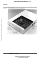
Figure 2.1 shows the right side of the MMDS station module, with the access panel
open. Callouts indicate the reset switch and power LED (on the front of the station
module), and the logic cable A and B connectors (on the right side of the station
module). (Alternate names for the logic cable connectors are pod A and pod B.) If you
use logic clip cables, always attach the black clip to ground.
Figure 2.2 shows the left side of the station module, with the access panel closed.
Callouts indicate the power cord socket, the power switch, and the 9-pin RS-232 serial
connector. The circular, +5 V out connector is reserved for possible future features. (A
spacer covers the final enclosure cutout, for a future connector.)
MMDS0508 Target Interface
For More Information On This Product,
Go to: www.freescale.com
2–9
Freescale Semiconductor, Inc.
Ins t a ll at ion
Introduction
M68MMDS0508 Station Module (Right Side)
Freescale Semiconductor, Inc...
Figure 2.1
2–10
MMDS0508 Target Interface
For More Information On This Product,
Go to: www.freescale.com
Freescale Semiconductor, Inc.
I ns t al la t io n
Configuring the Platform Board
Figure 2.2
M68MMDS0508 Station Module (Left Side)
Freescale Semiconductor, Inc...
Panel
Power Cord
Socket
Power Switch
9-Pin Serial
Connector
+5V Out
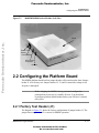
2.2 Configuring the Platform Board
The MMDS platform board has four jumper headers, all located near the front. Jumper
header J1 is for factory test. Jumper headers J2, J3, and J4 control the voltage levels
for ports A through D.
Before shipping the MMDS, factory personnel configure the
platform board correctly for virtually all users. You should not
reconfigure platform-board headers unless your EM user’s manual
tells you to.
NOTE
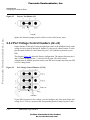
2.2.1 Factory Test Header (J1)
The diagram in Figure 2.3 shows the factory configuration of jumper header J1. The
jumper between pins 1 and 2 is correct for MMDS operation.
MMDS0508 Target Interface
For More Information On This Product,
Go to: www.freescale.com
2–11
Freescale Semiconductor, Inc.
Ins t a ll at ion
Configuring the Platform Board
Freescale Semiconductor, Inc...
Figure 2.3
Factory Test Header (J1)
(Ignore the alternate jumper position, which is reserved for factory tests.)
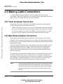
2.2.2 Port Voltage Control Headers (J2–J4)
Jumper headers J2 through J4, near the right front corner of the platform board, set the
voltage levels for ports A through D. Header J2 is the port A control; header J3 is the
port B control; header J4 is the control for port C or D (whichever pertains to your
EM).
The diagram Figure 2.4 shows the factory configuration. The jumpers between pins 1
and 2 of these headers set the +5-volt level for all ports. This is the correct
configuration for MMDS operation, unless your EM user's manual says that your EM
is a low-voltage board.
Figure 2.4
Port Voltage Control Headers (J2–J4)
If your EM can operate at low voltage, you can configure any of the ports for the lowvoltage level. To do so, reposition the corresponding header’s jumper to pins 2 and 3.
2–12
MMDS0508 Target Interface
For More Information On This Product,
Go to: www.freescale.com
Freescale Semiconductor, Inc.
I ns t al la t io n
Installing the EM
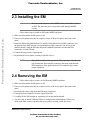
2.3 Installing the EM
CAUTION
Be sure to turn off power to the MMDS when you install or remove
an EM. This prevents power surges that could damage MMDS
circuits.
Freescale Semiconductor, Inc...
Follow these steps to install an EM in the MMDS enclosure:
1. Make sure that station module power is off.
2. Unscrew (one quarter turn) the two captive screws of the access panel, then remove the
panel.
3. Install the EM on the platform board: Carefully fit the female 96-pin DIN connectors (on
the bottom of the EM) onto the corresponding male DIN connectors (on the top of the
platform board). Snap the EM onto the plastic standoffs and make sure that the DIN
connectors are joined firmly.
4. Connect the target cable, if appropriate.
5. Reposition the access panel, securing it with the screws.
NOTE
Many EM boards have 64-pin female DIN connectors. Like their 96pin counterparts, these smaller connectors also mate with the male
DIN connectors of the platform board. The connector keys ensure
proper alignment.
2.4 Removing the EM
Follow these steps to remove an EM from the MMDS enclosure:
1. Make sure that station module power is off.
2. Unscrew (one quarter turn) the two captive screws of the access panel, then remove the
panel.
3. Disconnect the target cable from the EM target connectors.
4. Unsnap all plastic standoffs from the edges of the EM.
5. Carefully lift the EM straight up, separating it from the platform board.
6. You are ready to install a different EM or to configure the platform board. When you
finish such other actions, reposition the access panel, securing it with the screws.
MMDS0508 Target Interface
For More Information On This Product,
Go to: www.freescale.com
2–13
Freescale Semiconductor, Inc.
Ins t a ll at ion
Making Cable Connections
2.5 Making Cable Connections
You must connect the station module to the host computer and to line power.
According to your specific application, you also may need to connect the EM to your
target system, or to connect the logic clip cable assemblies.
Freescale Semiconductor, Inc...
2.5.1 Host Computer Connection
Connect the 9-lead serial cable between the MMDS 9-pin serial connector and the
COM1 serial port connector of the host computer.
• COM1 is the default serial port. You may use a different host serial port, provided
that you use the appropriate software startup command to specify the port number.
• A 9-to-25-pin adapter came with your MMDS. If the host serial port is a 25-pin
connector, use this adapter between the port connector and the serial cable.
2.5.2 Bus State Analyzer Connection
If your work session includes bus state analysis, you may need the logic clip cable
assemblies. The two logic clip connectors, pod A and pod B, let the analyzer capture
external events. Logic clip connections also let you input external clock signals for the
emulator and analyzer.
The pod A and pod B connectors are on the right side of the station module. Pod A is
nearest the station module power supply. These pod connectors correspond to the
cable A and cable B selections available in the bus state analyzer configuration
window. The Connector Information section includes pinout information for both
logic clip connectors.
If you need only one logic cable assembly, connect it to either pod A or pod B. Orient
the cable connector so that its pin 1 connects to pin 1 of the pod, according to the
keyed plastic. Connect the other end of the logic cable assembly to an external target
point. Optionally, connect the probe tips to the ball clips that come with the cable
assembly, then connect the ball clips to appropriate external test points.
NOTE
2–14
Always connect the black (ground) probe tip to an appropriate targetsystem ground point before connecting other clips to target points.
The pod A white probe is the external clock input for the emulator;
the pod B white probe of pod B is the external clock input for the
analyzer.
MMDS0508 Target Interface
For More Information On This Product,
Go to: www.freescale.com
Freescale Semiconductor, Inc.
I ns t al la t io n
Making Cable Connections
If you need the second logic cable assembly, connect it in the same way to the
remaining pod connector of the station module. Make target-system connections as for
the first cable.
2.5.3 Target Cable Connection
Freescale Semiconductor, Inc...
To connect the MMDS to a target system, you must use a target cable assembly: a
target cable and a target head.
NOTE
Press only on the rigid plastic terminators of the cable. Pressing on
the flexible part of the cable can damage the cable.
Follow these instructions:
1. Make sure that station module power is off; make sure that power is not applied to the
target system.
2. Remove the MMDS access panel, for access to the EM.
3. The EM has one or two target connectors, on its right side. Connect the target cable’s
emulator terminal to the EM target connectors.
4. Connect the target cable’s head terminator to the appropriate target head adapter.
NOTE
The EM user’s manual should identify the target head adapter
appropriate for your target system. Make sure that the adapter and the
target cable mate correctly.
5. Plug the target head adapter into the MCU socket (or surface-mount adapter) of the target
system.
6. Replace the access panel. (The target cable must run through the slit in the station-module
enclosure.)
2.5.4 Power Connection
The final MMDS connection is line power. The MMDS power switch is the rocker
switch on the left side of the station module. Set the power switch to OFF.
Insert the female end of the power cord into the power cord socket. Then plug the
other end of the cord into a line-power outlet and set the power switch to ON. The
green LED on the front of the station module lights to confirm system power.
MMDS0508 Target Interface
For More Information On This Product,
Go to: www.freescale.com
2–15
Freescale Semiconductor, Inc.
Freescale Semiconductor, Inc...
Ins t a ll at ion
Making Cable Connections
2–16
MMDS0508 Target Interface
For More Information On This Product,
Go to: www.freescale.com
Freescale Semiconductor, Inc.
3
Freescale Semiconductor, Inc...
Connector Information
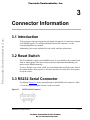
3.1 Introduction
This section provides pin assignments and signal descriptions for connectors common
to all MMDS systems. For similar information about EM connectors, see the
corresponding EM user's manual.
Additionally, this section explains the reset switch, and fuse replacement.
3.2 Reset Switch
RS-232 handshake signals control MMDS resets. A reset initializes the control board
from its startup point. If the host serial port does not implement handshaking, you
must reset the MMDS manually.
To do so, find the reset switch, which is recessed behind the small hole in the front of
the station module. Insert a probe or stiff wire into the reset switch hole. Press gently
to trip the switch.
3.3 RS232 Serial Connector
The diagram Figure 3.1 shows pin numbering for the MMDS serial connector. Table
3.1 lists the signals transmitted on the 9-lead serial cable.
Figure 3.1
RS232 Serial Connector
MMDS0508 Target Interface
For More Information On This Product,
Go to: www.freescale.com
3–17
Freescale Semiconductor, Inc.
C o n ne ctor I nfo rm at i o n
Logic Cables and Connectors
Freescale Semiconductor, Inc...
Table 3.1
. Serial Connector and Cable Pin Assignments
Connector Pin
Mnemonic
Signal
1
DCD
DATA CARRIER DETECT — Output signal that
indicates detection of an acceptable carrier
signal.
2
RX
RECEIVE DATA — Serial data output line.
3
TX
TRANSMIT DATA — Serial data input line.
4
DTR
DATA TERMINAL READY — Input signal that
indicates on-line/in-line/active status.
5
GND
GROUND
6
DSR
DATA SET READY — Output signal that
indicates on-line/in-line service/active status.
7
RTS
REQUEST TO SEND — Input signal that
requests permission to transfer data.
8
CTS
CLEAR TO SEND — Output signal that indicates
a ready-to-transfer data status.
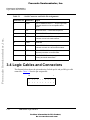
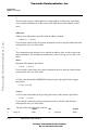
3.4 Logic Cables and Connectors
The diagram below shows the pin numbering for both pod A and pod B logic cable
connectors. Table 3.2 lists the pin assignments.
19
1
•
•
•
•
•
•
•
•
•
•
•
•
•
•
•
•
•
•
•
•
20
3–18
2
MMDS0508 Target Interface
For More Information On This Product,
Go to: www.freescale.com
Freescale Semiconductor, Inc.
C onne c t or I n forma t io n
Logic Cables and Connectors
Freescale Semiconductor, Inc...
Table 3.2
. Pod and Logic Cable Pin Assignments
Pod Pin
Pod A Signal
Pod B Signal
Probe Color
1
LC0
LC8
Brown (BRN)
2
GND
GND
3
LC1
LC9
4
GND
GND
5
LC2
LC10
6
GND
GND
7
LC3
LC11
8
GND
GND
9
LC4
LC12
10
GND
GND
11
LC5
LC13
12
GND
GND
13
LC6
LC14
14
GND
GND
15
LC7
LC15
16
GND
GND
17
EXT_OSC
TT_OSC
18
GND
GND
19
GND
GND
20
GND
GND
Red (RED)
Orange (ORG)
Yellow (YEL)
Green (GRN)
Blue (BLU)
Purple (PUR)
Gray (GRY)
White
Black
Note these points:
• Pins 19 of both pods provide connection to an external ground.
• Pod A pin 17 is the external clock input for the emulator. To use this source, make
the desired clock connection to the white probe tip, then use the OSC command to
select an external source.
MMDS0508 Target Interface
For More Information On This Product,
Go to: www.freescale.com
3–19
Freescale Semiconductor, Inc.
C o n ne ctor I nfo rm at i o n
Power Supply Fuse Replacement
• Pod B pin 17 is the external timetag input for the bus state analyzer. To use this
source, make the desired clock connection to the white probe tip, then use the
TIMETAG command to select an external time tag source for the analyzer.
Freescale Semiconductor, Inc...
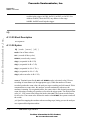
3.5 Power Supply Fuse Replacement
The station module power switch/connector assembly contains a standard 1/4 x 1 1/4
inch, 1.6-ampere, 250-volt ceramic, time-delay fuse. Figure 3.2 shows this assembly
with its door open (for fuse replacement).
Figure 3.2
Power Switch/Connector Assembly
Power Cord Socket
Fuse Door
Power Switch
Fuse
Tab
Figure 1. Power Switch/Connector Assembly
To replace the fuse, follow these steps:
1. Press the power switch OFF and disconnect the power cord.
3–20
MMDS0508 Target Interface
For More Information On This Product,
Go to: www.freescale.com
Freescale Semiconductor, Inc.
C onne c t or I n forma t io n
Power Supply Fuse Replacement
2. Insert a small screwdriver at the tab on the right edge of the switch/connector assembly.
(Figure 1 shows where to insert the screwdriver.) Gently pry open the assembly door,
which swings open to the left.
3. Remove the fuse holder from the switch/connector assembly. Remove the fuse from the
holder.
4. Insert the replacement fuse into the holder. Then re-install the holder in the switch/
connector assembly. Make sure that the fuse holder arrow points down. Close the
assembly door.
Freescale Semiconductor, Inc...
5. Reconnect the power cord. This completes fuse replacement.
MMDS0508 Target Interface
For More Information On This Product,
Go to: www.freescale.com
3–21
Freescale Semiconductor, Inc.
Freescale Semiconductor, Inc...
C o n ne ctor I nfo rm at i o n
Power Supply Fuse Replacement
3–22
MMDS0508 Target Interface
For More Information On This Product,
Go to: www.freescale.com
Freescale Semiconductor, Inc.
M MD S Ta rge t C omp one nt
4.1 Introduction
4
Freescale Semiconductor, Inc...
MMDS Target Component
4.1 Introduction
An advanced feature of the debugger for the embedded systems development world is
the ability to load different target components, which implement the interface with
target systems. This document introduces the MMDS0508 Modular Development
System for the MC68HC05 and MC68HC08 MCU families.
The MMDS is a Motorola interface that the debugger uses to communicate with an
external system (also called a target system).
This chapter describes MMDS0508 features, including memory mapping and the bus
analyzer.
With this interface, you can download an executable program from the debugger
environment. The destination of this program is an external target system, based on a
Motorola MCU, that executes the program. The debugger receives feedback of real
target-system behavior.
The debugger fully supervises and monitors the target-system MCU. That is, the
debugger controls the CPU execution. You can read and write in internal or external
memory (even when the CPU is running); you can single-step, run, or stop processes
in the CPU.
Uninvolved Components As an external MCU executes the code, the
MMDS target component cannot provide memory statistics. This
means that you cannot use the MMDS target component for
profiling, coverage analyzing, watchpoints, or I/O Simulation.
NOTE
MMDS0508 Target Interface
For More Information On This Product,
Go to: www.freescale.com
4–23
Freescale Semiconductor, Inc.
MM D S Ta r ge t C omp o n en t
4.2 General
4.2 General
This chapter describes the specific features of the MMDS0508, including emulation
memory mapping, as well as the function and purpose of the bus analyzer. The
explanations of windows and dialog boxes are with the explanations of corresponding
MMDS0508 features.
Freescale Semiconductor, Inc...
4.2.1 MMDS0508
The MMDS0508 is an emulator system, for CPU05 or CPU08 MCUs, that provides
emulation memory and a bus state analyzer.
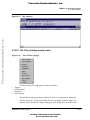
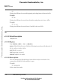
4.2.2 Configuration
The functions above are specific for the MMDS0508, so are available only with this
emulator component. To use these features select the corresponding menu commands
shown in Figure 4.1, such as MMDS0508 > ...
Figure 4.1
MMDS0508 Menu
These functions are part of the MMDS0508 Motorola Modular Development System.
Their supporting libraries consist of dialog boxes and routines to interface the
debugger and the hardware.
4–24
MMDS0508 Target Interface
For More Information On This Product,
Go to: www.freescale.com
Freescale Semiconductor, Inc.
M MD S Ta rge t C omp one nt
4.3 Definitions, Acronyms and Abbreviations
4.3 Definitions, Acronyms and
Abbreviations
4.3.1 DLL
Freescale Semiconductor, Inc...
Dynamic Link Library: A Microsoft Windows library file for dynamic linking.
4.3.2 Dynamic Linking
Dynamic Linking: A Windows process that links a function call in one module to the
actual function (in the library module), at run time.
4.3.3 MMDS0508 Server
The MMDS hardware access library that interfaces across the RS-232 port to the
MMDS0508 station.
4.3.4 Modal Dialog
A dialog that requires a response before you can continue.
4.3.5 MCU
Micro Controller Unit
4.3.6 EM
Emulation Module
4.4 Interfacing Your System and the
Target
The MMDS0508 box connects to an RS-232 serial port of your system.
4.4.1 Hardware Connection
Use the cables that came with the MMDS0508 to connect the host computer to the
MMDS0508 box (the diagram below depicts this connection). Configure the host
MMDS0508 Target Interface
For More Information On This Product,
Go to: www.freescale.com
4–25
Freescale Semiconductor, Inc.
MM D S Ta r ge t C omp o n en t
4.5 Loading the MMDS0508 Target
computer to be a data terminal, so that it sends data on the TxD lead and receives data
on the RxD lead (as shown in Figure 4.2 and as the MMDS0508 hardware manual
explains).
Freescale Semiconductor, Inc...
Figure 4.2
Hardware connection
4.5 Loading the MMDS0508 Target
Usually, the PROJECT.INI file specifies the target. To make the MMDS the target,
change the file’s “Target=” line to “Target=Motosil”. The MotoSIL driver
automatically detects the MMDS. However, if the driver detects nothing, an error
message informs you that the target is not connected to the expected port.
Additionally, the Communications Device Specification dialog box appears, so that
you can set the correct baud-rate and communication-port parameter values. See the
Communication Configuration section of this document for more details.
Another way to load the MMDS0508 target is selecting Set Target... from the
Component Menu (below) as shown in Figure 4.3, then choosing MotoSIL from the
list of possible targets.
Figure 4.3
4–26
Set Target
MMDS0508 Target Interface
For More Information On This Product,
Go to: www.freescale.com
Freescale Semiconductor, Inc.
M MD S Ta rge t C omp one nt
4.6 Communication Configuration
The MotoSIL driver automatically tries to find the MMDS target, behaving as text
above explains.
If MotoSIL does not detect a target, the MotoSIL item remains in the main menu bar as
shown in Figure 4.4:
Freescale Semiconductor, Inc...
Figure 4.4
Loading MotoSIL Target
But after successful target loading, the MMDS0508 menu replaces the Target or
MotoSIL menu in the main menu bar as show in Figure 4.5.
Figure 4.5
Loading MMDS Target
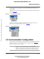
4.6 Communication Configuration
In most situations, the debugger uses its default values to set communication with the
MMDS automatically. In case of any problems, the dialog box show in Figure 4.6
appears, so that you can correct settings.
NOTE
Another way to open this dialog box is selecting MotoSIL >
Connect... from the menu bar. This method is appropriate if previous
connection attempts failed and MotoSIL still is in the main menu.
MMDS0508 Target Interface
For More Information On This Product,
Go to: www.freescale.com
4–27
Freescale Semiconductor, Inc.
MM D S Ta r ge t C omp o n en t
4.6 Communication Configuration
Freescale Semiconductor, Inc...
Figure 4.6
MotoSIL Communication Configuration
Make sure that host-computer parameter values are correct; make sure that the serialcommunication setting is correct. Otherwise, communication between the debugger
and the target is not possible.
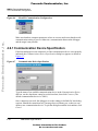
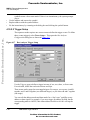
4.6.1 Communication Device Specification
If the host and target are not connected, or if the communication device is not properly
indicated, the Communications Device Specification dialog box appears as shown in
Figure 4.7 :
Figure 4.7
Communication Device Specification
Type the name of an available communication device in the Communication Device
edit box, use the drop-down control to set the baud rate, then click Connect. (The
default communication device is COM1.)
Once connection succeeds, the debugger saves the settings as defaults for later debug
sessions. Should the connection fail, a message box so informs you, so that you can
define a new communication device. To quit the dialog box and the environment, click
Cancel.
4–28
MMDS0508 Target Interface
For More Information On This Product,
Go to: www.freescale.com
Freescale Semiconductor, Inc.
M MD S Ta rge t C omp one nt
4.7 The Debugger Status Bar for the MMDS
NOTE
Saving the communication device and the baud rate through this
dialog box overrides environment variables BAUDRATE and
COMDEV of the default.env file.
Freescale Semiconductor, Inc...
4.6.2 Data Format
The MMDS0508 data format is 8 data bits, 1 stop bit, no parity, and a variable baud
rate. The default speed is 9600 baud, unless you change this default via the menu
selection MMDS0508>Communication....
Communication speeds of 1200 through 115200 baud are available, depending on the
host-computer hardware.
4.7 The Debugger Status Bar for the
MMDS
Once you have loaded the MMDS Target Component, the debugger status bar gives
specific information as shown in Figure 4.8:
Figure 4.8
The Debugger Status Bar
From left to right, this information is: the serial-communication baud rate, the
debugger running mode, the BUS analyzer mode, the MCU name (depending on the
MCU-Id), and the debugger status.
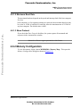
4.8 MMDS0508 Menu Entries
The Figure 4.9 show the MMDS0508 Menu Entries:
MMDS0508 Target Interface
For More Information On This Product,
Go to: www.freescale.com
4–29
Freescale Semiconductor, Inc.
MM D S Ta r ge t C omp o n en t
4.8 MMDS0508 Menu Entries
Freescale Semiconductor, Inc...
Figure 4.9
MMDS Menu Entries
4.8.1 Communication Baud Rate
You should specify the baud rate for host-computer-to-MMDS0508 communication
early in a session. The system operates most efficiently at the maximum baud rate that
the host computer supports.
You can modify this baud rate, as text below explains.
4.8.1.1 Communication
Select MMDS0508>Communication... to display the Communication Device
Specification dialog box as shown in Figure 4.10. Use the drop-down control to
specify the maximum value (115200 baud), or to specify the maximum rate your host
supports. If communication fails, the debugger reverts to the previous successful baud
rate.
Figure 4.10
4–30
Communication
MMDS0508 Target Interface
For More Information On This Product,
Go to: www.freescale.com
Freescale Semiconductor, Inc.
M MD S Ta rge t C omp one nt
4.8 MMDS0508 Menu Entries
4.8.1.2 Maximum Baud Rate
The maximum baud rate depends on the speed and interrupt load of the host computer.
For slow
book computers, or for computers running in a network, the maximum baud rate may
be as low as 19200. A buffered I/O card may allow the maximum rate of 115200 for
any host computer. The default value is 9600.
Freescale Semiconductor, Inc...
4.8.1.3 Show Protocol
If you check the Show Protocol checkbox, the system reports all commands and
responses in the command line window.
NOTE
Motorola or Hiware support personnel use this feature.
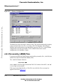
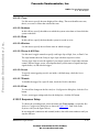
4.8.2 Memory Configuration
To view the memory layout, choose MMDS0508 > Memory Map... This opens the
Memory Configuration dialog box shown in Figure 4.11.
MMDS0508 Target Interface
For More Information On This Product,
Go to: www.freescale.com
4–31
Freescale Semiconductor, Inc.
MM D S Ta r ge t C omp o n en t
4.8 MMDS0508 Menu Entries
Freescale Semiconductor, Inc...
Figure 4.11
Memory Configuration
This dialog box shows the target’s memory setup. The system automatically loads this
setup if you check the Auto select according to MCU-Id checkbox. The debugger
identifies and sets the memory map through the processor MCU-Id. To open another
configuration, click the Open button. To save modifications to the current
configuration, click the Save... button.
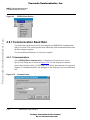
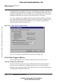
4.8.3 Personality (.MEM) Files
For proper operation, the Motosil target must load the personality file (.MEM file) that
matches the connected Emulation Module (EM).
The .MEM file filename format is:
0nnnnVxx.MEM
where ‘nnnn’ is the four-digit, hexadecimal ‘MCU-Id’ number of the MCU, and ‘xx’
is a two-digit version number.
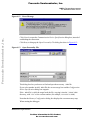
If the target cannot find this file, or if the file is not valid, the Error message box
appears as shown in Figure 4.12:
4–32
MMDS0508 Target Interface
For More Information On This Product,
Go to: www.freescale.com
Freescale Semiconductor, Inc.
M MD S Ta rge t C omp one nt
4.8 MMDS0508 Menu Entries
Freescale Semiconductor, Inc...
Figure 4.12
Error Message
Click Cancel to open the Communication Device Specification dialog box, instead of
establishing the connection.
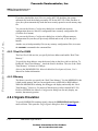
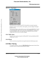
Click Retry to bring up the Open Personality File dialog box show in Figure 4.13:
Figure 4.13
Open Personality File
This dialog box lets you browse to find and open the necessary .MEM file.
If you select another invalid .MEM file, the error message box and the Configuration
Device Specification dialog box reappear.
If the .MEM file is valid, the target loads the file, copying it into the \PROG\MEM
directory, with ‘V00’ as the version number (for example, 00A18V00.MEM).
Note that the Memory Configuration dialog box displays the current memory map.
When starting the debugger:
MMDS0508 Target Interface
For More Information On This Product,
Go to: www.freescale.com
4–33
Freescale Semiconductor, Inc.
MM D S Ta r ge t C omp o n en t
4.8 MMDS0508 Menu Entries
If you have checked the Auto Select according MCU-ID checkbox, the system
automatically loads the default personality file for the MCU-ID. If this checkbox is
clear, the system automatically loads the most recently opened or saved memory map
file.
Freescale Semiconductor, Inc...
You can use the Memory Configuration dialog box to modify the memory
configuration, then save this new configuration into a memory configuration file.
(Click the Save button.)
You can use the Memory Configuration dialog box to load a different memory
configuration file (one that you previously defined and saved). (Click the Open
button.)
Another way to load personality files (or any memory configuration files) is to enter
the LOADMAP command in the command line.
4.8.3.1 Dual-Port RAM
The Dual-Port RAM area lets you specify the base address and enable “Real-Time
Memory”.
To specify the base address, enter the desired value in the Base Address edit box. To
Enable the “Real-Time Memory”, check the Enable checkbox. The size of the “RealTime Memory” is frozen at 1 kilobyte.
Also see the M68MMDS05/08, Motorola Modular Development System, User's
Manual for further information.
4.8.3.2 Memory
The Memory area lets you specify the “Real-Time Memory”. For the MMDS0508, this
is dual-ported memory that you can assigned to any valid RAM or ROM address.
While the MMDS0508 is running, the debugger can display and modify this “RealTime Memory.” However, if a portion of this memory overlays internal MCU I/O,
RAM, or EEPROM, the Memory Configuration dialog box can only display, not
monitor, that memory portion.
4.8.4 Signals Emulation
To specify MMDS0508 emulator signals, choose the MMDS0508>Emul Signals...
menu selection. This opens the Target Signals dialog box show in Figure 4.14.
4–34
MMDS0508 Target Interface
For More Information On This Product,
Go to: www.freescale.com
Freescale Semiconductor, Inc.
M MD S Ta rge t C omp one nt
4.8 MMDS0508 Menu Entries
Freescale Semiconductor, Inc...
Figure 4.14
Target Signals
This dialog box lets you specify the MCU clock and the reset signal connection.
Warning: in order to use any of these clock signals, you must configure EM jumper
headers correctly.
This dialog box displays settings that the system reads from the MMDS0508. Click Ok
to close the dialog box, and to write values back to the MMDS0508. Check the Save
and Reload checkbox to have the system save the configuration, then reload this
configuration the next time you start the debugger.
4.8.4.1 MCU Clock
The MCU Clock area lets you specify a different MCU clock, provided that the EM
configuration is correct.
4.8.4.2 Reset
The Reset area lets you specify the reset-signal connection with the target system.
4.8.5 Bus Tracing
To run the Bus Analyser, choose the MMDS0508>Bus Trace menu selection. Please
see the Bus Analyser section of this document for details.
MMDS0508 Target Interface
For More Information On This Product,
Go to: www.freescale.com
4–35
Freescale Semiconductor, Inc.
MM D S Ta r ge t C omp o n en t
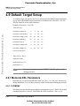
4.9 Default Target Setup
4.9 Default Target Setup
As with any target, you can use the Target menu to load the MMDS target component,
or you can set the MMDS target component as a default in the PROJECT.INI file.
This file should be in the project directory.
Example of PROJECT.INI file.
[DEFAULTS]
Freescale Semiconductor, Inc...
Window0=Source
0
0
50
40
Window1=Assembly
50
0
50
40
Window2=Register
50
40
50
30
Window3=Memory
50
70
50
30
Window4=Data
0
40
50
25
Window5=Command
0
65
50
20
Window6=Module
0
85
50
15
Target=Motosil
[Motorola ESL]
COMDEV=COM2
BAUDRATE=57600
SHOWPROT=1
NOTE
For more information about the PROJECT.INI file, please see the
debugger manual.
4.9.1 Motorola ESL Parameters
In normal use, you set these parameters in the project.ini file once, interactively,
during installation. You use these parameter values in subsequent debugging sessions.
4.9.1.1 COMDEV
This parameter specifies the host-computer communication port. COM1 is the default
communication device for PCs. The default for UNIX systems is /dev/ttya.
4–36
MMDS0508 Target Interface
For More Information On This Product,
Go to: www.freescale.com
Freescale Semiconductor, Inc.
M MD S Ta rge t C omp one nt
4.10 Bus Analyzer
For a PC: Any valid communication device (COM1,COM2,etc.).
Example:COMDEV=COM2
For SUN:Any valid communication device (/dev/ttya, etc.).
Example:comdev=/dev/ttyb
Freescale Semiconductor, Inc...
4.9.1.2 BAUDRATE
This parameter specifies the communication baud rate between the host computer and
the target system. The debugger default is 9600 baud, but you may set any of these
baud rates:
1200, 2400, 4800, 9600, 19200, 28800,
38400, 57600, 115200.
Example:BAUDRAUTE=19200
4.9.1.3 SHOWPROT
This parameter specifies whether to report commands and responses in the command
line window. To have the system report the commands and responses, give this
parameter the value 1. To have the system not do this reporting, give this parameter
the value 0. (Another way to specify reporting is checking the Show Protocol
checkbox of the Communication Device Specification dialog box.)
Please see the section Communication Configuration, Communication Device
Specification.
4.10 Bus Analyzer
4.10.1 Introduction to the Bus Analyzer
Except for emulating the target-system MCU, the most important feature that a
microcontroller development tool can offer is analyzing program execution activities
on the target MCU bus. This analysis lets you determine what is occurring in a system,
without actually affecting the system.
NOTE
The MMDS0508 bus analyzer shows the logical state of the MCU
bus. It does not show signal hold or setup times.
MMDS0508 Target Interface
For More Information On This Product,
Go to: www.freescale.com
4–37
Freescale Semiconductor, Inc.
MM D S Ta r ge t C omp o n en t
4.10 Bus Analyzer
4.10.1.1 Watchpoints
The MMDS0508 automatically maps available watchpoints to a proper bus analyzer
trigger pattern. You may use the bus analyzer to implement watchpoints. If you do,
however, you should not use the bus analyzer for other purposes!
Freescale Semiconductor, Inc...
4.10.1.2 Trace Modes
To gather pertinent bus data, you can operate the bus analyzer in different modes. The
various trace modes let you choose appropriate actions to take when a certain pattern
(event), or sequence of patterns, appears on the bus. To trigger the Bus analyzer,
define specific bus states as terms, and select a sequence of terms as a trigger event.
4.10.1.3 Trace Buffer
The trace buffer consists of 8,192 entries (or frames), each of which stores 96 bits.
When the bus analyzer is active and the emulator is running, the system strobes a
frame of the selected type into the trace buffer for each bus cycle. When trigger events
occur in a specified sequence, the system stores only the specified number of
additional frames.
4.10.1.4 Textual or Graphical
The bus analyzer displays data either textually or graphically. Use the horizontal and
vertical scroll bars, as in other Windows applications, to move around the displays.
4.10.2 Using the Bus Analyzer
The bus analyzer functions like any debugger component, and has its own menu to
control the features of the MMDS0508 Bus analyzer hardware. Another name for the
Bus Analyzer window is the Trace window. This is because the bus analyzer
corresponds to the trace component; you can load the bus analyzer by choosing
Open... Trace from the Component menu. Choose the MMDS0508 menu, then select
Bus Trace to open the Trace window (show in Figure 4.16) or the Bus Analyzer
(shown in Figure 4.15).
The three steps to using the Bus analyzer are: defining the data collection parameters,
collecting the specified bus data (running the program), and viewing the collected
data.
4–38
MMDS0508 Target Interface
For More Information On This Product,
Go to: www.freescale.com
Freescale Semiconductor, Inc.
M MD S Ta rge t C omp one nt
4.10 Bus Analyzer
Freescale Semiconductor, Inc...
Figure 4.15
Bus Analyzer
4.10.2.1 The Trace window popup menu
Figure 4.16
•
•
•
•
Trace Window popup
The bus analyzer has setup pages for these functions:
Triggers
Search pattern
Sequencer
Clock timing
These tabbed setup pages are part of the Bus Analyzer Configuration dialog box.
The Bus Analyzer Configuration dialog box lets you define symbolic names for
address values. When you change setup pages in the dialog box, the address and
MMDS0508 Target Interface
For More Information On This Product,
Go to: www.freescale.com
4–39
Freescale Semiconductor, Inc.
MM D S Ta r ge t C omp o n en t
4.10 Bus Analyzer
•
•
•
symbolic name values must match. If there is an inconsistency, the system prompts
you to:
Use the address and remove the symbol.
Replace address with the symbol address.
Fix the inconsistency by returning to the dialog box and clicking the symbol button.
Freescale Semiconductor, Inc...
4.10.2.2 Trigger Setup
The sequencer mode requires one or more terms to define the trigger events. To define
these events (triggers) select Trace>Setup.... This opens the Bus Analyzer
Configuration dialog box as shown in Figure 4.17 .
Figure 4.17
Bus Analyzer Trigger Setup
Use the Triggers page to define a trigger in terms of one, two, three, or four events.
For each term, define the read-write actions and clips.
These terms can be ranged or non-ranged triggers. For ranges, you can use A and B
together, and C and D together (two different ranges), or you can use B and C together
(one range).
You can edit the address masks and data masks for a “don’t care” qualifier on any
address or data signal. For example, if you set a trigger for address 0x1000, but the
corresponding mask is 0xFFFE, then either address 0x1000 or 0x1001 will trip the
trigger.
4–40
MMDS0508 Target Interface
For More Information On This Product,
Go to: www.freescale.com
Freescale Semiconductor, Inc.
M MD S Ta rge t C omp one nt
4.10 Bus Analyzer
4.10.2.2.1 Term
Use this area to specify the term displayed for editing. The term identifies an event;
that is, an event is a frame that satisfies the term.
4.10.2.2.2 Address
In this edit box, specify the address to which the system writes data or from which the
system reads data.
Freescale Semiconductor, Inc...
4.10.2.2.3 Data
In this edit box, specify the data that the system is to read or write.
4.10.2.2.4 Strobes
Use this area to specify the read/write state on which to trigger.
4.10.2.2.5 Group A & B Clips
Use this area’s toggle controls to specify each logic clip as High, Low, or Don’t Care.
The clips buttons show the Group A logic clips with their respective colors.
You use logic clips to trace the signals of your target system as it runs under software
control. When a trigger occurs, a breakpoint shows you the states of significant logic
signals before, at, and after the trigger.
4.10.2.2.6 Invert
To specify term triggering outside, not inside, a defined range, check the Invert
checkbox.
4.10.2.2.7 Disable
To disable the trigger for a specific term, check the Disable checkbox.
4.10.2.2.8 Clear
To clear all the changes in the Bus Analyzer Configuration dialog box, click the Clear
button.
To save your trigger settings and close the dialog box, click the OK button.
4.10.2.3 Sequencer Setup
To choose the recording mode, select the menu item Trace>Setup... to open the Bus
Analyzer Configuration dialog box as shown in Figure 4.18. Then click on the
Sequencer tab (see the figure below).
In non-triggered (continuous and counted) modes, data collection continues until you
stop the analyzer.
MMDS0508 Target Interface
For More Information On This Product,
Go to: www.freescale.com
4–41
Freescale Semiconductor, Inc.
MM D S Ta r ge t C omp o n en t
4.10 Bus Analyzer
In triggered modes, the analyzer uses your term definitions to track the occurrence of
events, then stop data collection according to some combination of the events. Each
term has an associated Pre Event count that counts events for that term. The sequencer
condition includes that term, once the count reaches the pre-event count.
Freescale Semiconductor, Inc...
An event is a pattern of bus signals (which can include address and data values) that
logic clips and miscellaneous MCU signals connect to the analyzer. Alternatively, an
event can be the negation of a defined pattern. You can define each signal to be
asserted, negated, or ignored (don't care).
Figure 4.18
Bus Analyzer Sequence Setup
Click on one of the nine option buttons to select the recording mode.
4.10.2.4 Non-Triggered Modes
In non-triggered modes, data collection continues until you stop the analyzer.
4.10.2.4.1 Continuous: All Cycles
Provides a real-time, non-invasive trace of MCU bus activities. The bus analyzer
stores all cycles, continuously recording bus data in the trace buffer during any
emulation of the user target system. This mode does not let you define qualifications
for triggering or halting data collection.
4–42
MMDS0508 Target Interface
For More Information On This Product,
Go to: www.freescale.com
Freescale Semiconductor, Inc.
M MD S Ta rge t C omp one nt
4.10 Bus Analyzer
4.10.2.4.2 Continuous: Events Only
Stores all the events that you defined in the Triggers page.
4.10.2.5 Counted Modes
In counted modes, data collection stops when the analyzer collects the specified
number of frames.
Freescale Semiconductor, Inc...
4.10.2.5.1 Counted: All Cycles
Records a specified number of cycles; you can trace that many cycles, of all types.
4.10.2.5.2 Counted: Events Only
Stores all events until it reaches the specified count. Then data collection stops.
4.10.2.6 Triggered Modes/Sequential Event Mode
In triggered modes, the analyzer uses term definitions to track event occurrence, then
stop data collection according to some combination of the events. Each term has an
associated Pre Event count that counts events for that term. The sequencer condition
includes that term, once the count reaches the pre-event count.
The sequencer trigger includes as many as four events, in one of four sequences. Each
event has a specified count; each trigger requires that specified count for each event.
Each count is a minimum: the event can occur additional times. An event is a pattern
of bus signals (which can include address and data values) that logic clips and
miscellaneous MCU signals connect to the analyzer. Alternatively, an event can be the
negation of a defined pattern. You can define each signal to be asserted, negated, or
ignored (don't care).
The sequences are:
4.10.2.6.1 Sequential: A + B + C + D
Select this option to start bus-analyser recording after any event occurs: A, B, C, or D.
Data storage ends after the specified number of post-trigger cycles.
4.10.2.6.2 Sequential: A -> B -> C, D<Select this option to start bus-analyser recording as soon as events A, B, and C occur,
in that order. But if event D occurs before event C, the analyzer must start the whole
sequence again with event A. Data storage ends after the specified number of posttrigger cycles. This mode is a simple, three-event sequence, if you do not define an
event D.
MMDS0508 Target Interface
For More Information On This Product,
Go to: www.freescale.com
4–43
Freescale Semiconductor, Inc.
MM D S Ta r ge t C omp o n en t
4.10 Bus Analyzer
4.10.2.6.3 Sequential: A + B -> C + D
Select this option to start bus-analyser recording when either of two sequences occurs:
(1) event A, followed by either event C or event D, or (2) event B, followed by either
event C or event D. Data storage ends after the specified number of post-trigger
cycles. You can simplify this sequence by leaving an event undefined.
Freescale Semiconductor, Inc...
4.10.2.6.4 Sequential: A -> B -> C-> D
Select this option to start bus-analyser recording as soon as events A, B, C, and D
occur, in that order. Data storage ends after the specified number of post-trigger
cycles.
4.10.2.6.5 Nth Event After A+B+C+D
Select this option to start bus-analyser storage of data that matches events A, B, C, and
D, until the analyzer stores the Nth event. Then, the analyzer stores as well the next
4096 cycles. The maximum N value is 4096, so this mode lets you store as many as
4096 events, followed by 4096 cycles.
4.10.2.7 Counted/Sequential Recording Mode
This paragraph explains how to switch beetween Counted and Sequential Recording
Mode.
4.10.2.7.1 Terminal Count/Post Trigger Cycles (1..8191)
For a counted mode, this edit box specifies the number of bus cycles that the analyzer
traces. For a sequential mode, this edit box specifies the number of post-trigger cycles
that the analyzer traces. The value range for this edit box is 1 through 8191. (For a
continuous modes, the analyzer ignores this value.)
4.10.2.7.2 Stop the emulator when recording completes
Check this checkbox to stop emulation as soon as the analyzer stops tracing bus
cycles. If this checkbox is clear, emulation continues, even after analyzer data storage
ends.
NOTE
The terminal count/post trigger cycles value applies only to counted
or sequential modes. For a counted mode, it is the number of cycles
the analyzer stores. For a sequential mode, it is the number of cycles
the analyzer stores after the trigger sequence occurs.
To save your sequencer settings and close the dialog box, click the OK button.
4–44
MMDS0508 Target Interface
For More Information On This Product,
Go to: www.freescale.com
Freescale Semiconductor, Inc.
M MD S Ta rge t C omp one nt
4.10 Bus Analyzer
4.10.2.8 Time Tag Clock Setup
Each frame of the trace buffer includes a time reference value, or time tag. You can
specify the clock signal that the analyzer uses for these time tags. To do so, choose the
Trace>Setup... menu selection, to open the Bus Analyzer Configuration dialog box as
shown in Figure 4.19. Then click on the Time Tag Clock tab.
Freescale Semiconductor, Inc...
Figure 4.19
Bus Analyze Time Clock Setup
4.10.2.8.1 Clock Frequency
In the Time Tag Clock Frequency area, select the clock-frequency source: an internal
oscillator at 16, 8, 4, 2, or 1 Mhz; an external clock; a bus clock; or a programmable
clock. In general, the faster clock rates provide higher resolution, so are appropriate
for faster emulator clock rates.
If you specify a programmable clock, you must enter the Hz frequency, 50 to 50,000,
in the edit box. If you specify a Nominal value, the analyzer uses the closest, Actual
frequency value. (A nominal value is a non-integer quotient of dividing 500,000 Hz by
an integer. An actual value is an integer quotient of dividing 500,000 Hz by an integer.
For example, suppose that you specify 986 in the edit box. 500,000 divided by the
integer 507 yields the non-integer quotient 986.193. If you specify a nominal value,
the analyzer rounds this value up to 1000, which is the integer quotient of 500,000
divided by 500.)
To save your time tag clock settings, and close the dialog box, click the OK button.
MMDS0508 Target Interface
For More Information On This Product,
Go to: www.freescale.com
4–45
Freescale Semiconductor, Inc.
MM D S Ta r ge t C omp o n en t
4.10 Bus Analyzer
4.10.3 Collecting Data
When your have initialized the emulator and the bus analyzer have been initialized,
and when you have connected any logic clips that you defined, emulation can begin.
Freescale Semiconductor, Inc...
4.10.3.1 Arming the Analyzer
Before you can start data collection, you must arm the bus analyzer. To do so, choose
the MMDS0508>Bus Trace>Arm Analyzer menu selection. The status bar shows
Armed status for the bus state analyzer, and the menu selection changes to Disarm
Analyzer.
4.10.3.2 Disarming the Analyzer
To stop the analyzer, choose the MMDS0508>Bus Trace>Disarm Analyzer menu
selection. The status bar shows Disarmed status for the bus state analyzer, and the
menu selection changes to Arm Analyzer.
4.10.3.3 Start Emulation
To begin emulation, choose the debugger Run>Continue menu selection, or enter any
other command that starts program execution. Emulation continues until a breakpoint,
a watchpoint, the bus analyzer, or you stop the emulation. When emulation stops, the
system updates data in the Bus Analyzer window (see below).
4.10.3.4 Status Bar
The debugger status bar shows the status of the bus analyzer. Before you arm the
analyzer, the status is Disarmed: not ready to collect data. After you arm the analyzer,
the status is Armed: ready to collect data. When emulation begins, the status is
Running: the analyzer is monitoring events. When the analyzer collects data, the status
is Analyzing.
4.10.3.5 Halt Data Collection
To halt data collection manually, choose the MMDS0508>Bus Trace>Disarm
Analyzer menu selection. This stops data collection, but does not stop emulation.
4.10.3.6 Halt Emulation
Stopping emulation also stops data collection, but leaves the analyzer armed. Data
collection resumes when emulation starts again.
4–46
MMDS0508 Target Interface
For More Information On This Product,
Go to: www.freescale.com
Freescale Semiconductor, Inc.
M MD S Ta rge t C omp one nt
4.10 Bus Analyzer
4.10.3.7 Recording Bus Data
When data collection begins, the bus analyzer starts recording bus data into the buffer.
When it reaches the end of the buffer, the Bus analyzer wraps around to the first buffer
frame and continues recording. This process continues until you disarm the analyzer,
until the analyzer records the specified number of frames, or until the analyzer records
the specified number of post-trigger cycles following the trigger event.
Freescale Semiconductor, Inc...
4.10.3.8 Trigger Event
When the analyzer detects a trigger event, it latches the event cycle into the buffer and
continues recording data until it collects the specified number of post-trigger cycles.
Then the bus analyzer stops collecting data, and its status changes to Disarmed.
At the same time the analyzer records the first post-trigger cycle, it automatically
begins searching for the next trigger event.
Subsequent events can occur while the bus analyzer collects post-trigger cycles for the
first event. In such a case, the analyzer continues collecting post-trigger cycles, but
marks the cycles for the subsequent events.
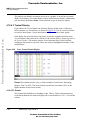
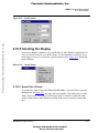
4.10.4 Viewing Collected Data
4.10.4.1 View Cycles
The bus analyzer provides several views of the collected cycles. At the end of cycle
collection, the trace buffer contains as many as 8192 of the most recently stored
frames. Those that have the highest numbers usually are the post-trigger frames. Those
that have the lowest numbers are the frames stored before the trigger occurred, if any.
When the bus analyzer is not in the Analyzing state, it displays data in the Trace
window.
4.10.4.2 Textual, Graphical or Instructions
To specify the type of bus-data display, select Textual, Graphical, or Instructions from
the Trace popup menu.
NOTE
If the sequencer did not specify collection of all frames (for example,
if it specified an events-only mode) the menu may not include the
Instructions selection.
MMDS0508 Target Interface
For More Information On This Product,
Go to: www.freescale.com
4–47
Freescale Semiconductor, Inc.
MM D S Ta r ge t C omp o n en t
4.10 Bus Analyzer
The analyzer can display its contents as text or as a graphic. You can have a textual
display of all frames, or a textual display of only instruction-start frames. Additionally,
you can choose the Trace>Items... menu selection to specify items for display.
4.10.4.3 Textual Display
Freescale Semiconductor, Inc...
If you choose the Textual format, the software displays all the frames of the trace
buffer contents, in a textual form, as shown in Figure 4.20. Use the vertical scroll bar
to scroll to other frames. Use the horizontal scroll bar to scroll to other signals.
Each display line gives the data of one frame: text below explains these data items.
You can add or remove data items. (Please see the section Adding / Removing Items in
the Trace Window.) The marker consists of two horizontal lines, which facilitate
reading the data items for a specific frame; the analyzer highlights the number of the
marked frame.
Figure 4.20
Trace Textual Format Display
Frame This column lists the cycle (or frame) number of each frame: identifying
integers, from 1 to 8191. The most recently stored frame has number 8191 (or the
highest number all the frames stored).
4.10.4.3.1 Events
This column lists identifiers of matching events. That is, if frame data matches any
event data definitions, the analyzer displays the event identifiers (A, B, C, or D) in this
column.
4–48
MMDS0508 Target Interface
For More Information On This Product,
Go to: www.freescale.com
Freescale Semiconductor, Inc.
M MD S Ta rge t C omp one nt
4.10 Bus Analyzer
4.10.4.3.2 Address
This column lists frame address bus values, as four hexadecimal digits. Each value is
the address on the address bus at the time the analyzer strobed the frame into the trace
buffer.
4.10.4.3.3 Data
Freescale Semiconductor, Inc...
This column lists frame data bus values, as two hexadecimal digits. Each value is the
values on the data bus at the time the analyzer strobed the frame into the trace buffer.
4.10.4.3.4 Time Tag
This column lists representations of the time tag count, stored when the analyzer
strobed each frame into the trace buffer. If the time tag clock was the bus clock, this
column shows the number of time-tag-clock cycles. If the time tag clock was a
different clock, this column shows a number of seconds (or fractions of seconds).
4.10.4.3.5 Time Measuring
To assign the time-tag value 0 to a frame, position your mouse cursor over the frame
entry and click the right mouse button. The Trace menu appears; select Set Time Base.
The analyzer re-displays all time-tag values relative to the bus cycle of the frame you
specified.
4.10.4.3.6 Control Signals
The remaining columns of the Trace dialog box show the values of control signals or
of logic clips.
4.10.4.4 Instructions Only Display
If you choose the Instructions format, the software displays only the frames where
instructions start as show in Figure 4.21. (The Instructions format is not available for
an Events Only recording mode.)
MMDS0508 Target Interface
For More Information On This Product,
Go to: www.freescale.com
4–49
Freescale Semiconductor, Inc.
MM D S Ta r ge t C omp o n en t
4.10 Bus Analyzer
Freescale Semiconductor, Inc...
Figure 4.21
Trace Instructions Only Format Display
4.10.4.5 Graphical Display
The figure below shows the graphical display of bus analyzer data. Selections of the
Trace menu let you switch between formats easily, at any time. The left column lists
data items. The next column lists the data values for the current frame. The rest of the
display presents those data values graphically, or with greater resolution. In a
graphical display, the marker consists of two vertical bars that enclose the information
of the current frame.
4.10.4.5.1 Zoom In or Out
The graphical display shown in Figure 4.22 lets you zoom in, to see more details, or
zoom out, for a better general view. Zoom in and Zoom out are selections of the Trace
popup menu.
Other ways to zoom in are choosing the Trace>Zoom In menu selection or pressing
the 'I' key of the keyboard.
4–50
MMDS0508 Target Interface
For More Information On This Product,
Go to: www.freescale.com
Freescale Semiconductor, Inc.
M MD S Ta rge t C omp one nt
4.10 Bus Analyzer
Freescale Semiconductor, Inc...
Figure 4.22
Trace Zoom Display
The figure above is a zoomed-in graphical display.
To zoom out, choose the Trace>Zoom Out menu selection, or press the O key of the
keyboard. The Figure 4.23 show below is a zoomed-out graphical display.
Figure 4.23
Trace Zoom In Display
Dragging the marker over a bus analyzer display may also generate updates in
component windows, such as the source and assembly windows. In other words,
MMDS0508 Target Interface
For More Information On This Product,
Go to: www.freescale.com
4–51
Freescale Semiconductor, Inc.
MM D S Ta r ge t C omp o n en t
4.10 Bus Analyzer
moving the marker over a bus analyzer textual or graphical display lets you view and
thoroughly examine data in continually updated windows.
4.10.4.5.2 ShowLocation
To activate the ShowLocation selection for a frame, select the frame, click the right
mouse button to activate the Trace menu, then select ShowLocation. Use a left mouse
click to position the marker. This automatically updates the source and assembly
windows.
Freescale Semiconductor, Inc...
4.10.4.5.3 Add / Remove Items in the Trace Window
You can add new items to the Trace window. The default items are: Frame, Events,
Address, Data, Time Tag, Instruction and R/W but you can add any other items of the
Items configuration dialog box. This same dialog box shown in Figure 4.24 lets you
remove items from the Trace window. You can even drag items into the window.
Figure 4.24
Items Configuration
To edit an item, change its color, or assign a specific name, click the More button. This
opens the Item content dialog box shown in Figure 4.25:
4–52
MMDS0508 Target Interface
For More Information On This Product,
Go to: www.freescale.com
Freescale Semiconductor, Inc.
M MD S Ta rge t C omp one nt
4.10 Bus Analyzer
Freescale Semiconductor, Inc...
Figure 4.25
Item Content
4.10.5 Scrolling the Display
You can use display scrollbars as you would those of other Windows applications, or
you can scroll to a specific trace buffer frame. It is also possible to search for one or
more trigger events, or to search for a specific pattern, as the Figure 4.26 illustration
below indicates.
Figure 4.26
Search Menu
4.10.5.1 Search for a Frame
To search for a frame, choose the Trace>Go to Frame... menu selection to open the
dialog shown in Figure 4.27, then enter the frame number. The marker moves to the
frame. If necessary, the system scrolls the bus analyzer window to make the frame
visible. If the system cannot find the specified frame, an error message reports that
fact.
MMDS0508 Target Interface
For More Information On This Product,
Go to: www.freescale.com
4–53
Freescale Semiconductor, Inc.
MM D S Ta r ge t C omp o n en t
4.10 Bus Analyzer
Figure 4.27
Search Frame
Freescale Semiconductor, Inc...
4.10.5.2 Search for Events
To search for an event occurrence, choose the Trace>Search>Event... menu
selection. This opens the Search Event Specification dialog box as shown in Figure
4.28. Check the checkboxes of one or more events.
Figure 4.28
Search Events
4.10.5.2.1 OK Button
To store your specification of events (not searching immediately), click OK.
4.10.5.2.2 Forward
To search forward for the next frame that matches your event specification, click
Forward.
4.10.5.2.3 Backward
To search backward for the next frame that matches your event specification, click
Backward.
4.10.5.2.4 Next Event
To search for the next occurrence of the specified event, choose the
Trace>Search>Next Event... menu selection. The analyzer searches forward from
the selected frame to find the next frame that matches your event specification.
(Pressing the keyboard N key is another way to activate this search.) If this search
4–54
MMDS0508 Target Interface
For More Information On This Product,
Go to: www.freescale.com
Freescale Semiconductor, Inc.
M MD S Ta rge t C omp one nt
4.10 Bus Analyzer
finds a matching frame, the marker moves to the frame. If necessary, the system
scrolls the bus analyzer window to make the frame visible. If the search does not find a
matching frame, an error message reports that fact.
Freescale Semiconductor, Inc...
4.10.5.2.5 Previous Event
To search for the previous occurrence of the specified event, choose the
Trace>Search >Previous Event menu selection. The analyzer searches backwards
from the selected frame to find the previous frame that matches your event
specification. (Pressing the keyboard P key, without activating the Trace menu, is
another way to activate this search.) If this search finds a matching frame, the marker
moves to the frame. If necessary, the system scrolls the bus analyzer window, to make
the frame visible. If the search does not find a matching frame, an error message
reports that fact.
4.10.5.3 Search for a Pattern
To search for a frame that matches a pattern, you must define the search pattern (an
address, a data word, logic clips, and four miscellaneous signals). To do so, choose the
Trace>Search>Pattern... menu selection. This opens the Pattern page of the Bus
Analyzer Configuration dialog box as shown in Figure 4.29:
Figure 4.29
Search Pattern
MMDS0508 Target Interface
For More Information On This Product,
Go to: www.freescale.com
4–55
Freescale Semiconductor, Inc.
MM D S Ta r ge t C omp o n en t
4.10 Bus Analyzer
Use this page to define the search pattern, in the same way you completed the Triggers
page.
The bus analyzer will look at specific collected cycles, match the frame that shows the
pattern, then display this frame in the debugger window.
4.10.5.3.1 Address
In this edit box, specify the Address to be matched.
Freescale Semiconductor, Inc...
4.10.5.3.2 Data
In this edit box, specify the Data value to be matched.
4.10.5.3.3 Strobes
Use this area to specify the R/W and LIR-X states to be matched.
4.10.5.3.4 Group A & B Clips
Use these areas’ toggle controls to specify each logic clip as High (H), Low (L) or
Don’t Care (X).
The clips buttons show the Group A and B logic clips with their respective colors.
You use logic clips to trace the signals of your target system as it runs under software
control. When a trigger occurs, a breakpoint shows you the states of significant logic
signals before, at, and after the trigger. Such states can be a search pattern to be
matched.
4.10.5.3.5 Invert
To specify matching any frame without the defined pattern, check the Invert checkbox.
4.10.5.3.6 OK Button
To save your pattern values and close the dialog box, click OK.
4.10.5.3.7 Cancel Button
To close the dialog box without changing any parameter values, click Cancel.
4.10.5.3.8 Next Pattern
To search for the next occurrence of the pattern, choose the Trace>Search>Next
Pattern menu selection. If the search does not find a matching pattern, an error
message reports that fact.
4.10.5.3.9 Previous Pattern
To search for the previous occurrence of the pattern, choose the
Trace>Search>Previous Pattern menu selection. If the search does not find a
matching pattern, an error message reports that fact.
4–56
MMDS0508 Target Interface
For More Information On This Product,
Go to: www.freescale.com
Freescale Semiconductor, Inc.
M MD S Ta rge t C omp one nt
4.10 Bus Analyzer
4.10.6 Dumping the Bus analyzer data to a file
To dump the Bus analyzer data to a file, choose the Trace>Dump... menu selection.
This opens the Dump Bus Analyzer Frames dialog box as shown in Figure 4.30.
Freescale Semiconductor, Inc...
Figure 4.30
Dump Bus Analyzer Frames
4.10.6.1 Dump File
This dialog box lets you specify frames in the bus analyzer window, then dump those
frames to a file.
In the Dump File edit box, enter the name of the file that will receive the dumped
frames.
4.10.6.1.1 Select
Click the Select button to open a standard file-select dialog box. You can use this
dialog box to specify the filename value for the Dump File edit box.
4.10.6.1.2 Frames to Dump
Use this area’s edit boxes to define the range of frames to be dumped to the file.
4.10.6.1.3 All
To have the analyzer dump all frames of the range, select the All option button.
4.10.6.1.4 Instructions
To have the analyzer dump only frames in which an instruction starts (that is, an
instruction also in the defined range), select the Instructions option button.
The trace dialog box display only frame as shown in Figure 4.31.
MMDS0508 Target Interface
For More Information On This Product,
Go to: www.freescale.com
4–57
Freescale Semiconductor, Inc.
MM D S Ta r ge t C omp o n en t
4.10 Bus Analyzer
Freescale Semiconductor, Inc...
Figure 4.31
Analyzer Dump Only Frame
4.10.6.1.5 OK Button
Click the OK button to close the dialog box and dump the bus analyzer data to the file.
4.10.6.1.6 Cancel Button
Click the Cancel button to close the dialog box without dumping any data.
4–58
MMDS0508 Target Interface
For More Information On This Product,
Go to: www.freescale.com
Freescale Semiconductor, Inc.
A
Freescale Semiconductor, Inc...
Appendix
A.1 MMDS Commands
This section describes MMDS-specific commands.
Use MMDS-specific commands as you would any other commands, typing them in
the Command Line component, or inserting them into a command file.
For further details about debugger commands, please see the debugger manual
sections Appendix, Debugger Commands and Command Line Component.
A.1.1 Baud Rate Command
BAUD
A.1.1.1 Short Description
sets the communication baud rate.
A.1.1.2 Syntax
BAUD [rate]
rate: Specifies the new baud rate; must be one of these decimal integer constants:
1200, 2400, 4800, 9600, 19200, 28800, 38400, 57600, 115200.
A.1.1.3 Description
The BAUD command sets or displays the baud rate for communication between the
system controller and the host computer. For maximum performance, the baud rate
should be as high as the host computer can accommodate. The maximum rate is
115200; the default baud rate is 9600.
MMDS0508 Target Interface
For More Information On This Product,
Go to: www.freescale.com
A–59
Freescale Semiconductor, Inc.
App en d ix
MMDS Commands
Without a rate value, the command displays the Communications Baud Rate
Specification dialog box for interactive rate selection. If the system does not support
the requested rate, the red message, “Error: <baud rate> is not a supported baud rate.”
appears in the Command Line window.
Example:
BAUD 57600
Freescale Semiconductor, Inc...
Changes the Baud Rate Command to 57600.
A.1.2 Trigger Commands
CT
A.1.2.1 Short Description
clear triggers.
A.1.2.2 Syntax
CT list | *
list: A list of trigger identifiers (A, B, C, or D).
*: All triggers.
A.1.2.3 Description
The CT command clears definition values of specified bus analyzer triggers (events),
A, B, C, or D. The command also disables these cleared triggers. Use the Set Trigger
(ST) command, or the bus analyzer configuration dialog box, to set trigger values.
windows. Triggers are enabled by Use the Trigger Enable (TE) and Trigger Disable
(TD) commands to enable and disable triggers.
Example:
CT A B
Clears triggers A and B.
Example:
A–60
MMDS0508 Target Interface
For More Information On This Product,
Go to: www.freescale.com
Freescale Semiconductor, Inc.
App en d ix
MMDS Commands
CT *
Clears all triggers.
This command clears both triggers of a range definition, even though just one of the
triggers is a parameter value.
Example:
Freescale Semiconductor, Inc...
If triggers C and D define a range, CT C clears both the triggers.
ST
A.1.2.4 Short Description
set trigger.
A.1.2.5 Syntax
ST [id [[!] [(address | address range | ,) [(data | data
range | ,) [(clips | ,) [LIR= (X | H | L)]]]] [;R | ;W| ;RW] [;D] ]]
A.1.2.6 Description
The ST command defines one of the four bus analyzer triggers. If this command
includes only a value or id parameter value, the command interpreter opens the
Trigger Specification dialog box. You can use the dialog box to set the trigger value
interactively.
id: The id of the analyzer trigger: A, B, C, or D.
!: The inversion operator for the entire trigger definition. Specifying !, as well as an
address, data value, and clip value, means that the trigger occurs when the address is
not the specified value, or the data value is not the specified value, or the clip value s
not the specified value. Specifying ! with a range is specification means that the
trigger occurs at values outside the range, and at the lowest value of the range.
address: Address that is to trip the trigger, specified with an address constant:
address[:mask]
If you include a mask value, the system comparison involves only the address bits that
correspond to ones (1s) of the mask.
MMDS0508 Target Interface
For More Information On This Product,
Go to: www.freescale.com
A–61
Freescale Semiconductor, Inc.
App en d ix
MMDS Commands
address range: A range of addresses to trip the trigger. To specify a range, use
starting and ending constants, or use a starting address and a length value:
start-address[:mask][..end-address]
or
start-address[:mask][,length]
Freescale Semiconductor, Inc...
If you include a mask value, the system comparison involves only the address bits that
correspond to ones (1s) of the mask. If you include a length and a mask, the system
adds the length to the start address, then applies the mask to the start address and to the
sum, to obtain the end address.
,: The comma directs the analyzer to not include an address, address range, data, data
range, or clip value in the trigger definition.
data:
Data value that is to trip the trigger:
value[:mask]
If you include a mask value, the system comparison involves only the value bits that
correspond to ones (1s) of the mask.
data-range:
A range of data values to trip the trigger. To specify a range, use start and end values,
or use a starting value and a length:
start-value[:mask][..end-value]
or
start-value[:mask][::length]
If you include a mask value, the system comparison involves only the value bits that
correspond to ones (1s) of the mask. If you include a length and a mask, the system
adds the length to the start value, then applies the mask to the start value and to the
sum, to obtain the end address.
clips
A 15-bit value that defines MMDS0508 analyzer logic clip signals for the trigger,
specified as:
clips[:mask]
If you include a mask, the system comparison involves only the value bits that
correspond to ones (1s) of the mask. For example, the code 0x1F:0x1F, sets all clips
A–62
MMDS0508 Target Interface
For More Information On This Product,
Go to: www.freescale.com
Freescale Semiconductor, Inc.
App en d ix
MMDS Commands
of Term A to H. Without a mask, the ST command uses the unmasked value 0x1F for
the clips.
Each trigger clip line has three options:
H - High
L - Low
X - Don’t Care
Freescale Semiconductor, Inc...
The bits of the clips and mask words are:
Bit:
0
Signal:
Group A- BRN
1
RED
2
ORG
3
YEL
4
GRN
6
LIR (active low)
;R: Trigger on a read bus cycle only.
;W: Trigger on a write bus cycle only.
;RW: Trigger on a read or write bus cycle.
;D: Disable trigger (set trigger value, but disable trigger).
LIR: Trigger on a specific value for LIR signal.
LIR=H triggers when LIR is high.
LIR=L triggers when LIR is low.
LIR=X triggers when LIR is high or low.
If either the address or the data value of this command is a range, the analyzer
interprets both values as ranges. For example, the analyzer interprets the command
STC 8 20..40 as STC 8.. 8 20..40; it interprets the command STC 8..9
20 as STC 8..9 20..20.
If the command lacks any R, W, or RW value, the trigger defaults to read/write.
You can set the LIR signal with the clips (bit 6) or the LIR option.
MMDS0508 Target Interface
For More Information On This Product,
Go to: www.freescale.com
A–63
Freescale Semiconductor, Inc.
App en d ix
MMDS Commands
A bit set in both the clips and masks sets the trigger to high (-H). A bit clear in clips,
but set in masks, sets the trigger to low (-L). A bit clear in a mask means that the
trigger does not depend on the state of the clip.
Examples:
STA 0x1000
Sets analyzer trigger A to match accesses at address $1000.
STB , 4
Freescale Semiconductor, Inc...
Sets analyzer trigger B to match accesses with a value of 4, at any address.
STC 8 20..40
Sets analyzer triggers C and D to match accesses having a value from 20 to 40, at
address 8.
STC 8..10 20
Sets analyzer triggers C and D to match accesses having the value 20, at any address
from 8 to 10.
NOTE
Mask bits that have the value 0 are “Don’t Care” bits: for those
positions of an address, data, or clip value, either a 0 or a 1 trips the
trigger. Mask bits set to 1 identify positions whose values must match
those of the specified address, data, or clip value. For Address
0xC000, Mask 0xFFFC, loading any of four values in the address bus
would trip the trigger: 0xC000, 0xC001, 0xC002, or 0xC003. For
Address 0x00B0, Mask 0xFFF0, any address in the range
0x00B0..0x00BF would trip the trigger.
TD
A.1.2.7 Short Description
trigger disable.
A.1.2.8 Syntax
TD list | *
A–64
MMDS0508 Target Interface
For More Information On This Product,
Go to: www.freescale.com
Freescale Semiconductor, Inc.
App en d ix
MMDS Commands
list: A list of trigger identifiers (A, B, C, or D), separated by comma or space
characters.
*: All triggers.
A.1.2.9 Description
Freescale Semiconductor, Inc...
The TD command disables specified triggers. Use the Set Trigger (ST) command to set
triggers; use the Trigger Enable (TE) command to enable triggers. Use the Clear
Triggers (CT) command to clear triggers.
Example:
TD A B
Disables triggers A and B.
Example:
TD *
Disables all triggers.
TE
A.1.2.10 Short Description
trigger enable.
A.1.2.11 Syntax
TE list | *
list: A list of trigger identifiers (A, B, C, or D), separated by comma or space
characters.
*: All triggers.
A.1.2.12 Description
The TE command enables specified triggers. Use the Set Trigger (ST) command to set
triggers; use the Trigger Disable (TD) command to disable triggers. Use the Clear
Triggers (CT) command to clear triggers.
Example:
MMDS0508 Target Interface
For More Information On This Product,
Go to: www.freescale.com
A–65
Freescale Semiconductor, Inc.
App en d ix
MMDS Commands
TE A B
Enables triggers A and B.
Example:
TE *
Freescale Semiconductor, Inc...
Enables all triggers.
A.1.3 Bus Analyzer Commands
ARM
A.1.3.1 Short Description
arm bus analyser.
A.1.3.2 Syntax
ARM
A.1.3.3 Description
The ARM command arms the bus analyzer. When armed, the analyzer records bus
cycles while the emulator is executing user code. Arming the analyzer clears the
current contents of the trace buffer. Use the disarm analyzer (DARM) command to
disarm the analyzer.
DARM
A.1.3.4 Short Description
disarm bus analyser.
A–66
MMDS0508 Target Interface
For More Information On This Product,
Go to: www.freescale.com
Freescale Semiconductor, Inc.
App en d ix
MMDS Commands
A.1.3.5 Syntax
DARM
A.1.3.6 Description
Freescale Semiconductor, Inc...
The DARM command disarms the bus analyzer. When disarmed, the analyzer does not
record bus cycles. If the bus analyzer is disarmed already, this command does nothing.
ARM arms the analyzer
GE
A.1.3.7 Short Description
go to event.
A.1.3.8 Syntax
GE list | * [;B]
;B: Specifies a backward search; without this option, the command directs a forward
search.
list:A list of events (A, B, C, or D), separated by space or comma characters.
A.1.3.9 Description
The GE command searches in the analyzer trace buffer for a frame that matches the
specified event. A forward search begins with the frame immediately following the
current frame; a backward search begins at the frame immediately preceding the
current frame.
Example:
GE A B
Moves the cursor to the next frame which contains the event A and/or B.
MMDS0508 Target Interface
For More Information On This Product,
Go to: www.freescale.com
A–67
Freescale Semiconductor, Inc.
App en d ix
MMDS Commands
GF
A.1.3.10 Short Description
go to frame.
Freescale Semiconductor, Inc...
A.1.3.11 Syntax
GF frame
frame: Frame number, in the range 1..8191. This number must be decimal number,
regardless of the current default number base.
A.1.3.12 Description
The GF command moves the cursor to a specified trace buffer frame. If the
command’s frame-number value is greater than the number of frames stored in the
buffer, the command moves your display to the buffer’s last frame.
Example:
GF 4096
Moves the cursor to frame 4096.
Example:
GF 8191
Moves the cursor to the last frame in the buffer.
GP
A.1.3.13 Short Description
Go to Analyzer Search Pattern.
A.1.3.14 Syntax
GP [;B]
;B: Specifies a backward search; without this option, the command directs a forward
search.
A–68
MMDS0508 Target Interface
For More Information On This Product,
Go to: www.freescale.com
Freescale Semiconductor, Inc.
App en d ix
MMDS Commands
A.1.3.15 Description
Freescale Semiconductor, Inc...
The GP command searches the analyzer trace buffer for a frame that matches the
defined search pattern. (Use the SP command to define the pattern.) A forward search
begins at the frame immediately following the current frame. A backward search
begins at the frame immediately preceding the current frame.
When the search finds a matching frame, the system positions the line cursor on the
frame, in the center of the screen. If no frame matches the pattern, the line cursor does
not move. If no search pattern is defined, this command searches for any pattern: that
is, the line cursor moves to the next line (or preceding line).
Example:
GP
Searches forward for the next frame that matches the search pattern.
Example:
GP ;B
Searches backward for the previous frame that matches the search pattern.
LT
A.1.3.16 Short Description
log trace.
A.1.3.17 Syntax
LT [range]
range: The range of frames (decimal numbers) to be copied. Without a range value,
this command copies all frames in the trace buffer.
A.1.3.18 Description
The LT command copies contents of the bus analyzer trace buffer to the log file, in the
current view format. The target must be stopped to execute an LT command.
Example:
MMDS0508 Target Interface
For More Information On This Product,
Go to: www.freescale.com
A–69
Freescale Semiconductor, Inc.
App en d ix
MMDS Commands
LF logfile
Open the logging file.
Example:
LT
Copy all the trace buffer to the logging file.
Example:
Freescale Semiconductor, Inc...
NOLF
Close the logging file.
SC
A.1.3.19 Short Description
set analyzer clock.
A.1.3.20 Syntax
SC [timetag [frequency]]
timetag: One of these values:
OSC1MHZ (1 Mhz oscillator)
OSC2MHZ (2 Mhz oscillator)
OSC4MHZ (4 Mhz oscillator)
OSC8MHZ (8 Mhz oscillator)
OSC16MHZ (16 Mhz oscillator)
EXT (external clock)
BUS (bus clock)
PROGRAM (programmable clock)
frequency: Time tag clock frequency for the programmable clock, 50 Hz to 50 kHz
(enter a decimal hertz value). The programmable clock source has a fundamental
frequency of 500,000 Hz; the actual frequency the system uses is the quotient of
A–70
MMDS0508 Target Interface
For More Information On This Product,
Go to: www.freescale.com
Freescale Semiconductor, Inc.
App en d ix
MMDS Commands
500,000 Hz divided by an integer. Thus, 50000 is valid, but 49000 is not. (If you
specify 49000, the system rounds the value up the the next higher valid frequency:
50000.)
Freescale Semiconductor, Inc...
A.1.3.21 Description
The SC command sets the source for the time tag clock, which increments the trace
buffer time tag. If this command includes no parameter values, the command
interpreter opens the Bus Analyzer Configuration dialog box. You can use the Time
Tag Clock page to reach the Clock Specification dialog box, then set the clock sources
interactively.
Example:
SC PROGRAM 100
Sets the programmable clock, running at 100Hz, as the time clock source.
Example:
SC OSC8MHZ
Sets the 8 Mhz oscillator as the time tag clock source.
SP
A.1.3.22 Short Description
set analyzer search pattern.
A.1.3.23 Description
The SP command defines a search pattern for the bus analyzer trace buffer. The go to
pattern (GP) command starts the search for the pattern defined by the most recent SP
command. If the SP command includes no parameter values, the command interpreter
opens the Bus Analyzer Configuration dialog box. You can use the Pattern page to
define the pattern interactively.
A.1.3.24 Syntax
SP [!] [(<address> | ,) [(<data> | ,) [(<clips> | ,)[LIR =
(X | L | H)]]]][;R | ;W| ;RW]
MMDS0508 Target Interface
For More Information On This Product,
Go to: www.freescale.com
A–71
Freescale Semiconductor, Inc.
App en d ix
MMDS Commands
!:
The inversion operator, which applies to a single address or data value. Specifying
!sets a pattern on addresses or data values other than the specified address or data
value.
address:
Address part of the pattern, specified with an address constant:
Freescale Semiconductor, Inc...
address [:mask]
If you include a mask value, the system comparison involves only the address bits that
correspond to ones (1s) of the mask.
,:
The comma directs the analyzer to not include an address, data, or clips value in the
pattern definition. The omitted item matches any value of its type (so is a don’t care
entry).
data:
Data part of the pattern, specified as:
value [:mask]
If you include a mask value, the system comparison involves only the value bits that
correspond to ones (1s) of the mask.
A 15-bit value that defines MMDS0508 analyzer logic clip signals for the trigger,
specified as:
clips[:mask]
clips:
A 16-bit value that defines the logic clip signal values of the pattern, specified as:
clips [:mask]
If you include a mask, the system comparison involves only the value bits that
correspond to ones (1s) of the mask.
The bits of the clips and mask words are:
Bit:
0
A–72
Group A -
Signal:
BRN
Bit:
8
Group B -
MMDS0508 Target Interface
For More Information On This Product,
Go to: www.freescale.com
Signal:
BRN
Freescale Semiconductor, Inc.
App en d ix
MMDS Commands
Bit:
1
2
3
4
5
6
7
Signal:
RED
ORG
YEL
GRN
BLU
LIR
GRY
Bit:
9
10
11
12
13
14
15
Signal:
RED
ORG
YEL
GRN
BLU
VLT
GRY
Freescale Semiconductor, Inc...
;R: Search for a read bus cycle only.
;W : Search for a write bus cycle only.
;RW: Search for either a read or write bus cycle.
LIR: Search for a specific LIR-signal value:
LIR=H searches for LIR high.
LIR=L searches for LIR low.
LIR=X searches for LIR either high or low.
A bit set in both the clips and masks detects the pattern if the bit is high (-H). A bit is
clear in clips but set in masks detects the pattern if the bit is low (-L). A bit clear in a
mask means that pattern detection does not depend on the state of the clip.
Examples:
SP 0x1000
Sets accesses at address $1000 to be part of the analyzer search pattern.
SP , 4
Sets accesses with the data value 4, at any address, to be part of the analyzer search
pattern.
SP 8 20
Sets accesses with the data value 20, at address 8, to be part of the analyzer search
pattern.
Mask bits that have the value 0 are “Don’t Care” bits: for those
positions of an address, data, or clips value, either a 0 or a 1 trips the
trigger. Mask bits set to 1 identify positions whose values must match
those of the specified address, data, or clip value. For Address
0xC000, Mask 0xFFFC, loading any of four values in the address bus
NOTE
MMDS0508 Target Interface
For More Information On This Product,
Go to: www.freescale.com
A–73
Freescale Semiconductor, Inc.
App en d ix
MMDS Commands
would trip the trigger: 0xC000, 0xC001, 0xC002, or 0xC003. For
Address 0x00B0, Mask 0xFFF0, any address in the range
0x00B0..0x00BF would trip the trigger.
Freescale Semiconductor, Inc...
SQ
A.1.3.25 Short Description
set sequencer.
A.1.3.26 Syntax
SQ [mode [count] [;S] ]
mode: One of these values:
ALL (records all bus cycles)
EVENT (records only events)
SEQ0 (sequential A+B+C+D)
SEQ1 (sequential A+B->C+D)
SEQ2 (sequential A->B->C D<-)
SEQ3 (sequential A->B->C->D)
SEQ4 (nth event after A+B+C+D)
count: Terminal count for the ALL and EVENT modes (a decimal value). Directs
recording of count frames (of the appropriate type). When the number of frames
recorded reaches the count value, the analyzer stops recording and is disarmed. If this
command has no count value, the analyzer records continuously whenever the
emulator is running. For sequential modes, the count value is the decimal post-trigger
count, directing recording of count bus cycles after the trigger point. The default count
value is 1. If no count value follows the mode value ALL, the system records frames
for all cycles. If no count value follows the mode value EVENT, the system records all
the events.
;S: Specifies stopping the emulator when recording stops, letting you use the analyzer
as a sequenced breakpoint machine.
A–74
MMDS0508 Target Interface
For More Information On This Product,
Go to: www.freescale.com
Freescale Semiconductor, Inc.
App en d ix
MMDS Commands
A.1.3.27 Description
The SQ command sets the analyzer sequencer mode. If this command includes no
parameter values, the command interpreter opens the Bus Analyzer Configuration
dialog box: select the Sequencer Setup dialog box to program the sequencer
interactively. Selecting from the Setup menu is another way to open the Sequencer
Setup dialog box.
Example:
Freescale Semiconductor, Inc...
SQ ALL 100
Specifies 100 bus cycles. After 100 cycles, the analyzer disarms itself and stops
recording.
Example:
SQ EVENT 10 ;S
Specifies recording 10 event cycles, then stopping the emulator.
TT
A.1.3.28 Short Description
display time tag difference.
A.1.3.29 Syntax
TT [sframe [eframe]]
sframe: The starting frame number.
eframe: The ending frame number; without this value, the system uses the end frame
in the trace buffer to calculate the difference.
A.1.3.30 Description
The TT command displays the difference between the time tags in the two trace frames
of the analyzer display. Without frame-number values, this command displays the
difference between the beginning and ending frames
Example:
MMDS0508 Target Interface
For More Information On This Product,
Go to: www.freescale.com
A–75
Freescale Semiconductor, Inc.
App en d ix
MMDS Commands
TT
Displays the difference between the beginning and ending frames in the trace buffer.
Example:
TT 80
Displays the difference between frame 80 and the ending frame in the trace buffer.
Example:
Freescale Semiconductor, Inc...
TT 10 40
Displays the difference between frames 10 and 40 in the trace buffer.
VA
A.1.3.31 Short Description
analyzer view.
A.1.3.32 Syntax
VA [MODE=(MIX | INS | GRAPH)]
MODE=: When followed by one of the three following keywords, specifies the mode of
the bus analyzer window display.
MIX: Mixed view mode.
INS: Instruction view mode.
GRAPH: Graphical view mode.
A.1.3.33 Description
The VA command specifies the display format for the analyzer trace buffer. This
command is valid only if the bus analyzer is open.
Example:
VA MODE=MIX
Selects mixed view mode.
A–76
MMDS0508 Target Interface
For More Information On This Product,
Go to: www.freescale.com
Freescale Semiconductor, Inc.
App en d ix
MMDS Commands
A.1.4 Target Signal Emulation Commands
SIG
Freescale Semiconductor, Inc...
A.1.4.1 Short Description
set emulator signals.
A.1.4.2 Syntax
SIG [ [ENABLE] signal {signal}] [ DISABLE signal
{signal}]
signal: The signal to be enabled or disabled: RESETIN or RESETOUT.
ENABLE: Connect the signal from the target system.
DISABLE: Disconnect the signal from the target system.
A.1.4.3 Description
The SIG command enables or disables control signals from the target MCU. If the
command specifies any signals, but lacks either keyword ENABLE nor DISABLE, the
command enables the signals.
Example:
SIG ENABLE RESETIN
Enables the “reset in” signal from the target system.
A.1.5 Reset Commands
RESET
A.1.5.1 Short Description
resets target MCU.
MMDS0508 Target Interface
For More Information On This Product,
Go to: www.freescale.com
A–77
Freescale Semiconductor, Inc.
App en d ix
MMDS Commands
A.1.5.2 Syntax
RESET [GO|STOP]
GO: Resets the MCU and does a Go from Reset.
STOP: Resets the MCU and stops (default).
A.1.5.3 Description
Freescale Semiconductor, Inc...
The RESET command resets the target MCU.
Examples:
Reset Go
Resets the MCU and does a GO from Reset.
Reset
Resets the MCU and stops (default setting).
A.1.6 Other Commands
LOADMAP
A.1.6.1 Short Description
loads memory map.
A.1.6.2 Syntax
LOADMAP fileName | MCUID
fileName: a standard full path of a file that defines a memory map.
MCUID: the MCU identifier. If the command includes an MCUID value, the system
loads a memory map from the file that matches this value.
A–78
MMDS0508 Target Interface
For More Information On This Product,
Go to: www.freescale.com
Freescale Semiconductor, Inc.
App en d ix
MMDS Commands
A.1.6.3 Description
The LOADMAP command loads a memory map from a file. The file specification
must be the full pathname. If the file is in the current directory, the characters “.\”
must precede the name (for example: LOADMAP .\00123V22.MEM).
Example:
LOADMAP 0xC17
Freescale Semiconductor, Inc...
Loads a memory map from a file that matches this MCU identifier (68HC08AX48).
Note that the MCUID identifies an MCU, not an EM Board. The memory map
filename has this format:
0nnnnVvv.MEM
where ‘nnnn’ is the four-digit, hexadecimal ‘MCU-ID’, and ‘vv’ is a two-digit version
number.
MEM
A.1.6.4 Short Description
displays the memory map.
A.1.6.5 Syntax
MEM
A.1.6.6 Description
The MEM command displays the current memory map.
Example:
in>MEM
Type
Addresses
Comment
------------------------------------------------------IO
0.. 3F PRU or TOP
TOP board resource or the PRU
NONE
40.. 4F NONE
RAM
50.. 64F RAM
NONE
650.. 7FF NONE
EEPROM
800.. A7F EEPROM
NONE
A80..3DFF NONE
MMDS0508 Target Interface
For More Information On This Product,
Go to: www.freescale.com
A–79
Freescale Semiconductor, Inc.
App en d ix
MMDS Commands
Freescale Semiconductor, Inc...
ROM
3E00..FDFF ROM
IO
FE00..FE1F PRU or TOP
TOP board resource or the PRU
NONE
FE20..FFDB NONE
ROM
FFDC..FFFE ROM
COP
FFFF..FFFF special ram for cop
RT MEM
0.. 3FF (disabled)
-------------------------------------------------------
OSC
A.1.6.7 Short Description
selects Emulator Clock Frequency command.
A.1.6.8 Syntax
OSC [rate | source]
A.1.6.9 Description
The OSC command selects the emulator clock frequency: one of five internally
generated frequencies (16 Mhz, 8 Mhz, 4 Mhz, 2 Mhz, or 1 Mhz), or an external clock
source. The firmware sets the default emulator clock rate, adapting it to the current
frequency.
Entering this command without parameters opens the corresponding dialog box.
OSC [rate | source]
where rate is:
OSC1MHZ
Selects the 1 Mhz oscillator.
OSC2MHZ
Selects the 2 Mhz oscillator.
OSC4MHZ
Selects the 4 Mhz oscillator.
OSC8MHZ
Selects the 8 Mhz oscillator.
OSC16MHZ
Selects the 16 Mhz oscillator.
Where source is: EXT
A–80
Selects an external clock source.
MMDS0508 Target Interface
For More Information On This Product,
Go to: www.freescale.com
Freescale Semiconductor, Inc.
App en d ix
MMDS Commands
Example:
OSC OSC8MHZ
// Use the 8 Mhz internal
emulator clock.
Freescale Semiconductor, Inc...
PROTOCOL
A.1.6.10 Short Description
controls Show Protocol functionality.
A.1.6.11 Syntax
PROTOCOL [ON | OFF]
ON: Reports commands and responses in the command line window (default value for
this command).
OFF: Does not report commands or responses in the command line window; does not
log commands or responses in the log file.
A.1.6.12 Description
The PROTOCOL command controls reporting commands and responses in the
command line window. Entering this command without a parameter value has the
same effect as entering the command with the parameter value ON.
RTMEM
A.1.6.13 Short Description
configures real time memory.
A.1.6.14 Syntax
RTMEM address [;E|;D]
address: base address of a real time memory block (default is 0).
;E: Enables the real time memory block (the default for this command).
MMDS0508 Target Interface
For More Information On This Product,
Go to: www.freescale.com
A–81
Freescale Semiconductor, Inc.
App en d ix
MMDS Commands
;D: Disables the real time memory block.
A.1.6.15 Description
The RTMEM command lets you enable or disable real time memory.
Example:
RTMEM 0x1000 ;D
Freescale Semiconductor, Inc...
Disables the real time memory block at base address $1000.
A–82
MMDS0508 Target Interface
For More Information On This Product,
Go to: www.freescale.com
Freescale Semiconductor, Inc.
Index
Symbols
E
.MEM 32
EM
A
Installing 13
Removing 13
Emulation 34
Freescale Semiconductor, Inc...
ARM 66
Arming 46
F
B
Fuse Replacement 20
BAUD 59
BAUDRATE 36, 37
Bus Analyzer 37
G
GE 67
GF 68
GP 68
C
Cables, Connecting
Host Computer 14
Power 15
Target 15
Collecting Data 46
COM1 28
COMDEV 36
Commands 59
Communication Baud Rate 30
Communication Configuration 25
Configuration 24
Memory 31
Continuous 42
Counted 43
CT 60
D
H
Hardware Installation
Configuring the Platform Board 11
Connecting Cables 14
Fuse Replacement 20
Installing the EM 13
Introduction 9, 17
Pin Assignments, Connector 17
Removing the EM 13
Reset Switch 17
Signal Descriptions, Connector 17
I
Interfacing
Hardware Connection 25
J
DARM 66
Data Dump 57
Data Format 29
Disarming 46
Display
Graphical 50
Instructions Only 49
Textual 48
DLL 25
Dual-Port RAM 34
Dumping 57
Dynamic Linking 25
Jumper Headers
Factory Test (J1) 11
Port Voltage Control (J2–J4) 12
K
keyword Hardware Connection 25
L
LOADMAP 34, 78
LT 69
MMDS0508 Target Interface
For More Information On This Product,
Go to: www.freescale.com
IDX–83
Freescale Semiconductor, Inc.
Freescale Semiconductor, Inc...
M
MCU Clock 35
MCU clock 35
MCU-Id 32
MEM 79
Memory 34
Memory Configuration 31
Memory Map 31
Menu 29
MMDS0508 24
MMDS0508 Server 25
Modes
counted 43
non-triggered 42
triggered 43
MotoSIL 26
Motosil 36
N
Nth Event 44
O
OSC 80
P
Personality file 32
Pin Assignments, Connector 17
Platform Board, Configuration 11
Pod 19
Port Voltage Control Jumper Headers (J2–J4) 12
PROJECT.INI 26, 36
PROTOCOL 81
Protocol 31
R
RESET 77
Reset 35
Reset signal connection 35
RTMEM 81
S
SC 70
Scrolling 53
Scrolling Display 53
IDX–84
MMDS0508 Target Interface
For More Information On This Product,
Go to: www.freescale.com
Freescale Semiconductor, Inc...
Freescale Semiconductor, Inc.
Search 53
Event 54
Frame 53
Pattern 55
Sequencer Setup 41
Sequential 43
Serial 18
Show Protocol 31
ShowLocation 52
SHOWPROT 37
SIG 77
Signals 34
SP 71
SQ 74
ST 61
Status Bar 29
System
Components 6
Connections
14
T
Target 26
Target Setup 36
TD 64
TE 65
Textual Display 48
Time Tag Clock 45
Trace Buffer 38
Trace Modes 38
Trigger 47
Trigger Events 40
Trigger Setup 40
TT 75
V
VA 76
Viewing Data 47
W
Watchpoints 38
Z
Zoom 50
MMDS0508 Target Interface
For More Information On This Product,
Go to: www.freescale.com
IDX–85
Freescale Semiconductor, Inc...
Freescale Semiconductor, Inc.
IDX–86
MMDS0508 Target Interface
For More Information On This Product,
Go to: www.freescale.com