1
Datalogger
User Manual
Bär Industrie-Elektronik GmbH
Lange Straße 87
D-90762 Fürth
Deutschland / Germany
Phone +49 911 970590
Fax +49 911 9705950
Internet: www.baer-gmbh.com
E114005204052
Page 2 of 76
DLX
User Manual
Bär Industrie-Elektronik GmbH / Lange Straße 87 / D-90762 Fürth / Phone +49 911 970590⋅Fax +49 911 9705950
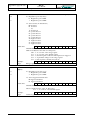
Table of contents
1 Scope of application ................................................................................................................................... 6
1.1 Graphical representation of the application environment .................................................................... 6
1.1.1 Short description....................................................................................................................... 6
2 Device description ...................................................................................................................................... 7
2.1 Features................................................................................................................................................ 7
2.2 Block circuit diagram of modules........................................................................................................ 9
2.2.1 Description of the block circuit diagram of modules ............................................................. 10
3 Functional description ............................................................................................................................. 11
3.1 Functional circuit diagram ................................................................................................................. 11
3.2 Data protection and safety ................................................................................................................. 12
3.3 Program code..................................................................................................................................... 12
3.4 Setting of parameters (programming the DLX)................................................................................. 12
3.4.1 Program protection switch...................................................................................................... 13
3.5 Pulse processing ................................................................................................................................ 14
3.5.1 Pulse inputs ............................................................................................................................ 15
3.5.2 Signal current input ................................................................................................................ 16
3.5.3 Summation registers ............................................................................................................... 16
3.5.4 Pulse outputs .......................................................................................................................... 17
3.5.5 Apparent demand and cos(ϕ) ................................................................................................. 17
3.5.6 Maximum demand calculation ............................................................................................... 17
3.5.7 Maximum demand reset ......................................................................................................... 18
3.5.8 Periodical buffer (billing data) ............................................................................................... 18
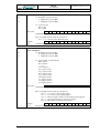
3.6 Time basis.......................................................................................................................................... 19
3.6.1 Setting the real time clock ...................................................................................................... 19
3.6.2 Automatic summertime switching.......................................................................................... 19
3.6.3 Synchronization...................................................................................................................... 19
3.6.4 Registration period ................................................................................................................. 20
3.7 Rate dependent processing................................................................................................................. 20
3.7.1 Rate control ............................................................................................................................ 20
3.7.2 Rate calendar .......................................................................................................................... 20
3.7.3 Rate control inputs.................................................................................................................. 22
3.8 Storage of measurements ................................................................................................................... 23
3.8.1 Internal memory ..................................................................................................................... 23
3.8.1.1 Unit restart (loading of factory default settings)....................................................... 23
3.8.1.2 Unit warm start......................................................................................................... 23
3.8.1.3 Unit cold start ........................................................................................................... 23
3.8.1.4 Erase memory........................................................................................................... 23
3.8.2 Security mechanisms for data storage .................................................................................... 23
3.8.3 Block diagram of internal memory......................................................................................... 24
3.8.4 Capacity of internal memory .................................................................................................. 24
3.8.5 Capacity of backup memory (PC-Card) ................................................................................. 25
3.9 Control inputs .................................................................................................................................... 25
3.10 Outputs .............................................................................................................................................. 26
3.11 Communication ................................................................................................................................. 26
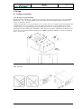
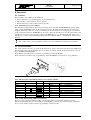
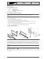
4 Design ........................................................................................................................................................ 27
4.1 Sealing arrangements......................................................................................................................... 27
4.1.1 Housing for panel mounting................................................................................................... 27
4.1.2 19” rack .................................................................................................................................. 27
4.2 Installation diagram ........................................................................................................................... 28
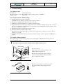
5 Commissioning ......................................................................................................................................... 29
5.1 Delivery state..................................................................................................................................... 29
5.2 Preparation for commissioning.......................................................................................................... 29
5.3 Supply voltage selection .................................................................................................................... 29
DLX
User Manual
Page 3 of 76
Bär Industrie-Elektronik GmbH / Lange Straße 87 / D-90762 Fürth / Phone +49 911 970590⋅Fax +49 911 9705950
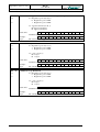
5.4 Terminals ........................................................................................................................................... 30
5.4.1 Location of the terminals........................................................................................................ 30
5.4.2 Connector X1 (Supply voltage) .............................................................................................. 30
5.4.3 Connector X2 (control inputs, relay outputs) ......................................................................... 31
5.4.4 Connector X3 (pulse inputs 1-6, outputs 1-4)......................................................................... 32
5.4.5 Connector X4 (pulse inputs 7-16) .......................................................................................... 33
5.4.6 Connectors X5 and X6 ........................................................................................................... 33
5.4.7 Input and output modules ....................................................................................................... 34
6 Operation .................................................................................................................................................. 36
6.1 Display............................................................................................................................................... 36
6.1.1 Keys........................................................................................................................................ 36
6.1.2 Light emitting diodes (LED) .................................................................................................. 36
6.1.3 Standard display mode ........................................................................................................... 37
7 Menus ........................................................................................................................................................ 38
7.1 Flow diagram ..................................................................................................................................... 38
7.2 Legend of flow diagrams ................................................................................................................... 39
7.3 Password input................................................................................................................................... 39
7.4 Select language .................................................................................................................................. 41
7.5 Scroll list............................................................................................................................................ 42
7.6 Main menu item „Display alarms” ................................................................................................... 43
7.7 Main menu item „Info“...................................................................................................................... 44
7.7.1 Current values......................................................................................................................... 45
7.7.2 Energy values ......................................................................................................................... 46
7.7.3 Load profiles........................................................................................................................... 47
7.7.4 Billing data ............................................................................................................................. 48
7.7.4.1 Energy current .......................................................................................................... 48
7.7.4.2 Energy Cumulative................................................................................................... 49
7.7.4.3 Maximum demand.................................................................................................... 49
7.7.5 Spontaneous events ................................................................................................................ 50
7.7.6 Table address.......................................................................................................................... 50
7.7.7 Version ................................................................................................................................... 51
7.8 Main menu item „Set Parameters“..................................................................................................... 51
7.8.1 Factory settings (unit restart or system restart)....................................................................... 51
7.8.2 Erase memory......................................................................................................................... 52
7.9 Main menu item „Maintenance“........................................................................................................ 53
7.9.1 Set time................................................................................................................................... 54
7.9.2 Register PC-Card.................................................................................................................... 54
7.9.3 Deactivate PC-Card ................................................................................................................ 54
7.9.4 Enter counter values ............................................................................................................... 55
7.9.5 Initiate maximum reset ........................................................................................................... 55
7.9.6 Display test ............................................................................................................................. 55
7.10 Main menu item „Erase Alarms“....................................................................................................... 56
8 Interfaces................................................................................................................................................... 57
8.1 General............................................................................................................................................... 57
8.1.1 Automatic protocol recognition:............................................................................................. 57
8.2 Service interface ................................................................................................................................ 57
8.2.1 Pin allocation of the SUB-D (female) service interface RS232.............................................. 57
8.2.2 Connection PC/Laptop ↔ Service interface .......................................................................... 57
8.3 Data interface (optional, X6) ............................................................................................................. 58
8.3.1 Pin allocation of the data interface RS232 SUB-D (female) .................................................. 58
8.3.2 Pin allocation of the data interface RS232 SUB-D (male) ..................................................... 58
8.3.3 Pin allocation of the data interface RS232 (X6 at 19” rack)................................................... 58
8.3.4 Pin allocation of the M-Bus data interface ............................................................................. 59
8.3.5 Pin allocation of the fiber optic connector.............................................................................. 60
9 Modem (Optional) .................................................................................................................................... 61
Page 4 of 76
DLX
User Manual
Bär Industrie-Elektronik GmbH / Lange Straße 87 / D-90762 Fürth / Phone +49 911 970590⋅Fax +49 911 9705950
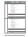
9.1 Default settings for the integrated modem......................................................................................... 61
9.2 Modem interface (X5) ....................................................................................................................... 61
9.2.1 Pin allocation of the modem interface.................................................................................... 61
10 DCF77 receiver (Option) ......................................................................................................................... 62
10.1 Function ............................................................................................................................................. 62
10.2 Setting the parameters for the receiver module ................................................................................. 62
10.3 Commissioning.................................................................................................................................. 62
10.3.1 Connection ............................................................................................................................. 62
10.3.2 Alignment of the receiver module .......................................................................................... 62
11 PC-Card .................................................................................................................................................... 63
11.1 Permitted PC-Card's .......................................................................................................................... 63
11.2 Treatment advice for PC-Cards ......................................................................................................... 63
11.3 Inserting a PC-Card ........................................................................................................................... 63
11.4 Activating a PC-Card......................................................................................................................... 64
11.5 Deactivating a PC-Card ..................................................................................................................... 64
11.6 Removing a PC-Card......................................................................................................................... 64
11.7 Data storage on a PC-Card ................................................................................................................ 64
12 Registration of measurements................................................................................................................. 65
12.1 Factory settings.................................................................................................................................. 66
13 Fault displays............................................................................................................................................ 67
13.1 LC display.......................................................................................................................................... 67
13.2 Light Emitting Diodes ....................................................................................................................... 69
13.2.1 LED AL1 Warning ................................................................................................................. 69
13.2.2 LED AL2 Device fault ........................................................................................................... 69
13.3 Message buffers ................................................................................................................................. 69
13.4 Fault indication output....................................................................................................................... 69
14 Technical data .......................................................................................................................................... 70
15 Glossary .................................................................................................................................................... 74
Appendix A
Data retrieval protocols ...............................................................................................................from A2
SCTM ..........................................................................................................................................from A2
IEC 60870-5-102 .......................................................................................................................from A21
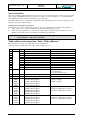
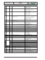
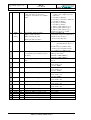
Appendix B
Table addresses............................................................................................................................ from B2
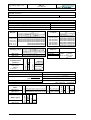
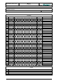
Appendix C
List of parameters and constants.................................................................................................. from C2
DLX
User Manual
Page 5 of 76
Bär Industrie-Elektronik GmbH / Lange Straße 87 / D-90762 Fürth / Phone +49 911 970590⋅Fax +49 911 9705950
Table of figures
Figure 1, Application environment .................................................................................................................... 6
Figure 2, Block circuit diagram of modules....................................................................................................... 9
Figure 3, Functional circuit diagram................................................................................................................ 11
Figure 4, Program protection switch................................................................................................................ 13
Figure 5, Block circuit diagram of impulse processing ................................................................................... 14
Figure 6, Block diagram of internal memory................................................................................................... 24
Figure 7, Dimensions and sealing arrangements for covers............................................................................. 27
Figure 8, Sealing arrangements for 19” rack ................................................................................................... 27
Figure 9, Dimensions of 19” rack .................................................................................................................... 28
Figure 10, Dimensions of mounting points...................................................................................................... 28
Figure 11, Location of the switch .................................................................................................................... 29
Figure 12, Voltage selection switch................................................................................................................. 29
Figure 13, Location of the terminals (Housing for panel mounting) ............................................................... 30
Figure 14, Location of the terminals (19” rack)............................................................................................... 30
Figure 15, Connector X1 (Supply voltage) ...................................................................................................... 30
Figure 16, Connector X2 ................................................................................................................................. 31
Figure 17, Connector X3 ................................................................................................................................. 32
Figure 18, Connector X4 ................................................................................................................................. 33
Figure 19, Layout of operation controls and indicators ................................................................................... 36
Figure 20, Standard display mode ................................................................................................................... 37
Figure 21, Flow diagram of menus .................................................................................................................. 38
Figure 22, Legend of flow diagrams................................................................................................................ 39
Figure 23, Flow diagram for password input ................................................................................................... 39
Figure 24, Entering a password ....................................................................................................................... 40
Figure 25, Flow diagram for menu item „Select Language“ ........................................................................... 41
Figure 26, Flow diagram for the scroll list....................................................................................................... 42
Figure 27, Flow diagram for alarm display...................................................................................................... 43
Figure 28, Flow diagram for menu item “Info” (current values) ..................................................................... 45
Figure 29, Flow diagram for menu item „Info“ (energy values)...................................................................... 46
Figure 30, Flow diagram for menu item „Info“ (load profile values) .............................................................. 47
Figure 31, Flow diagram for menu item „Info” (billing data) ......................................................................... 48
Figure 32, Flow diagram for the menu item „Info“ (spontaneous events) ....................................................... 50
Figure 33, Flow diagram for menu item „Info“ (table addresses).................................................................... 50
Figure 34, Flow diagram for menu item „Info“ (version)................................................................................ 51
Figure 35, Flow diagram for menu „Set Parameters“ ...................................................................................... 51
Figure 36, Flow diagram for menu item „Maintenance“ ................................................................................. 53
Figure 37, Flow diagram for menu item „Erase alarms“ ................................................................................. 56
Figure 38, Service interface ............................................................................................................................. 57
Figure 39, Fiber optic connector ...................................................................................................................... 60
Figure 40, Pin allocation of the telephone cable .............................................................................................. 61
Figure 41, DCF77 receiver module AWS0...................................................................................................... 62
Figure 42, Inserting a PC-Card ........................................................................................................................ 63
Page 6 of 76
DLX
User Manual
Bär Industrie-Elektronik GmbH / Lange Straße 87 / D-90762 Fürth / Phone +49 911 970590⋅Fax +49 911 9705950
1 Scope of application
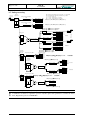
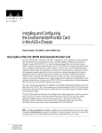
1.1 Graphical representation of the application environment
Figure 1, Application environment
1.1.1 Short description
The DLX was designed as a powerful device for the registration and processing of electrical impulses from
energy meters, flow meters, heat flow processors and similar devices. It is meant for installation in bulk energy supply points, power station injection points, at special contract customers and industrial premises. Load
profiles, calculated values and spontaneous events are processed and stored on the site. This data can be interrogated by hierarchically higher processing devices via a number of interfaces.
•
The direct serial service interface (RS232) can be used to read and program the DLX via the programming software DLXPARA. Compatible data retrieval software (e.g. SIGLON) can be used to read data
on site.
•
The data interface (RS232, M-Bus or RS485) can be used to retrieve data on site via data retrieval software. Alternatively an external modem can be connected (via RS232).
•
The modem interface can be used to connect via the internal modem (optional) to the public switched
telephone network (PSTN) and data can be uploaded to a PC.
An optional PC-Card (backup memory) can be used to store the content of the periodical buffers and the
spontaneous event buffer as well as part of the device parameters. This PC-Card can be read by compatible
data retrieval software via standard card readers and a PC.
Load management (switching off and on of loads) can be realized on site via external load management software, using the control outputs of the DLX.
DLX
User Manual
Page 7 of 76
Bär Industrie-Elektronik GmbH / Lange Straße 87 / D-90762 Fürth / Phone +49 911 970590⋅Fax +49 911 9705950
2 Device description
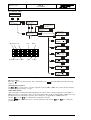
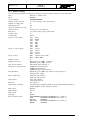
2.1 Features
Display
LCD (illuminated supertwist), 4 lines of 20 characters,
controlled by keypad or control input ANZ
16 / pulse inputs,
7 / control inputs,
6 / outputs,
2 / alarms,
1 / PC-Card (memory card),
3 / interfaces
4 keys (Enter, Exit, Cursor-Up, Cursor-Down)
Service interface (programming/data retrieval): RS232
Data interface (optional): RS232, Fiber-optic, RS485 or M-Bus
Internal modem (optional)
Internal memory: 1MByte (Flash-Memory)
Backup memory: PC-Card (memory card) acc. to JEIDA-Standard,
max. 4MByte (SRAM or Flash)
Real time clock, buffered by GoldCap,
max. deviation 30 sec/month at 25°C (10ppm)
reserve: min. 7 days without auxiliary voltage
Via SYN input or external DCF77 receiver (optional)
6 (standard), optional up to16
S0 (IES), wipe (IEW), bi-current / bi-polar (IED),
analogue (signal current): 0..20mA or 4..20mA
Light emitting diodes
(Number / Usage)
Keypad
Interfaces
Data memory
Clock
Synchronization
Pulse inputs
Input types
Control inputs
1 (standard: SYN),
optional up to 7 (SYN, TR1÷4, RSTX, ANZ, LOG1÷4)
Control input types
S0 (standard), wipe
Outputs
2 mech. relays (change-over for Alarm1÷2/MPA1÷2/RSTA
tariff rates1÷4/LOG1÷4), max.: 250V/2A
4 wipe (IAW/pulse), max.: 250V/100mA (optional)
Digits of energy registers
4, 6, 8 (programmable)
Digits of demand registers
4, 6, 8 (programmable)
Registration periods
2
Period lengths
MP1:
MP2:
1, 2, 3, 4, 5, 6, 10, 12, 15, 20, 30, 60 minutes (programmable)
in addition 2, 3, 6, 12, 24 hours
Load profile types
Register reading, register increment or demand
Totals
1 (standard), optional up to 4
Cos(ϕ) registers (alternatively
apparent energy)
1 (standard), optional 2
Internal tariff calendar
Yes
Max. number of energy and
demand rates
4/4
Demand registration
Yes, with storage of date and time
Number of stored previous demand values
Min. 20
Switching between summer and
winter time.
automatic
Radio clock
optional: external DCF77-Receiver
Event buffer
min. 780 events
DLX
Page 8 of 76
User Manual
Bär Industrie-Elektronik GmbH / Lange Straße 87 / D-90762 Fürth / Phone +49 911 970590⋅Fax +49 911 9705950
Transmission protocols
Internal modem
Transmission speed.
Service:
Data:
Modem:
SCTM, IEC 60870-5-102, automatic protocol recognition
Housing for panel mounting: LGO 834 (9600 Baud), optional
19” rack: UniMod (9600 Baud), optional
9600 Baud
300, 600, 1200, 2400, 4800, 9600 Baud (programmable)
300, 1200, 2400 Baud, 9600 Baud
Transmission mode
Full duplex
Program protection
Via password and protection switch
Remote programming
Not permitted
Auxiliary voltage
100/115VAC or 200/230VAC, internal selection switch
Power consumption
< 20W
Enclosure
Housing for panel mounting or 19” rack
Connectors
Pluggable terminals with screws
Number of terminals
60 (inputs and outputs) + 3 (auxiliary voltage)
Dimensions
Housing for panel mounting: ca. 175mm × 300mm × 150mm
19” rack: ca. 215mm × 130mm × 265mm (W × H × D)
Programming software, programming cable, PC-Card (memory card)
Ancillary equipment
DLX
User Manual
Page 9 of 76
Bär Industrie-Elektronik GmbH / Lange Straße 87 / D-90762 Fürth / Phone +49 911 970590⋅Fax +49 911 9705950
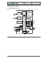
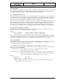
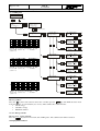
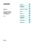
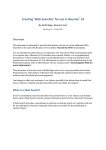
2.2 Block circuit diagram of modules
The block circuit diagram below gives an overview of the individual modules of the DLX.
Figure 2, Block circuit diagram of modules
Page 10 of 76
DLX
User Manual
Bär Industrie-Elektronik GmbH / Lange Straße 87 / D-90762 Fürth / Phone +49 911 970590⋅Fax +49 911 9705950
2.2.1 Description of the block circuit diagram of modules
The DLX has a modular design. It consists of the following modules:
• Power supply module
Converts the external auxiliary voltage (110VAC or 230VAC) into the internal device voltages (5VDC
and 12VDC).
• Connection module
Input pulse signals and control signals are galvanically isolated from the process via input modules and
connected to the processor module. Pulse output signals and control output signals are serviced via the
relay module and an output module.
• Processor module
The processor module controls all functions of the DLX. Apart from the micro controller it contains the
internal program and data memory, a real time clock and capacitors to bridge power failures. The displays
and the keypad are also connected to the processor module.
• Display module
Stored data can be displayed via the LC-Display. The LED display shows the status of individual process
signals. Commands to the micro controller are entered via the keypad. The program protection switch,
which is used to protect the parameters of the DLX from alterations, is located on the inside of the display
module.
DLX
Page 11 of 76
User Manual
Bär Industrie-Elektronik GmbH / Lange Straße 87 / D-90762 Fürth / Phone +49 911 970590⋅Fax +49 911 9705950
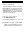
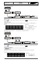
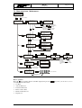
3 Functional description
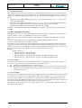
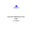
3.1 Functional circuit diagram
The functional circuit diagram below shows and overview of the individual functions of a DLX device.
Input pulse
conditioning,
Totalling.
Cos (ϕ)
Apparent
demand
In7 to In16
Input modules
Inputs
In1 to In6
Keypad
Input
Registers
Alarms
Parameters
Scroll-List
LCD
Firmware
Output modules
Program memory
Out1 to Out4
Rel1 and Rel2
Max. demand
for billing
Events
Gold-Cap
Data
Load profile
MP1, MP2
CPU
Sync.
Ctl*
Clock
Rate
control
Ctl*
Tariffs
Logic
inputs
Ctl*
Aerial
PC-Card
* programmable control inputs Ctl1 to Ctl7
Figure 3, Functional circuit diagram
Voltage
monitor
~
Auxiliary voltage US
Data
retrieval
SCTM
IEC870
LCD, LED
Outputs
Alarms
Power
supply
Parameter
Data
retrieval
SCTM
IEC870
Modem
Registration period
registers
MP1, MP2
Service
Process memory
Communication
Outputs
Page 12 of 76
DLX
User Manual
Bär Industrie-Elektronik GmbH / Lange Straße 87 / D-90762 Fürth / Phone +49 911 970590⋅Fax +49 911 9705950
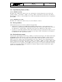
3.2 Data protection and safety
All individual storage cells of the DLX are checked continually:
• RAM memory: All storage cells are tested at least once in every 24 hours. The memory contents are first
written to a safe place, then a number of different bit patterns (A5, 5A, 00, FF) are written and read back
into each memory cell. Finally the original memory content is written back. If a defective memory cell is
detected (bit patterns from read and write operations are not identical), an error message is shown at the
display and the error notification relay is activated. The error message is available for remote data retrieval.
• Firmware memory: The content of the firmware memory is tested on an ongoing basis: a checksum is
calculated over the whole memory content. If a difference is detected between the calculated checksum
and the stored checksum, an error message is shown on the display and the error notification relay is activated. The error message is available for remote data retrieval.
• Data memory: Data for parameters, spontaneous events, reset events and for each registration period are
stored in physically separate areas (sectors). When data is written, the correctness of the write cycle is confirmed for each individual byte of data by an additional read cycle. Additionally a checksum is calculated for
each data set. When data sets are read, another checksum is calculated and compared with the stored checksum.
The data set will only be processed if both checksums are identical.
3.3 Program code
The program code (firmware) is stored in the firmware memory (Flash memory). Program code can be
loaded with a special software application via the service interface. Therefore no change of EPROM is required for firmware updates. Loading of a new firmware is only permitted in non-secured certification mode
(in this mode the unit is not certified and the program protection switch is set to “Disable”). All internal
memory will be cleared and the factory settings (see page 66) will be activated.
3.4 Setting of parameters (programming the DLX)
Parameter settings in the DLX can be altered via the programming software DLXPARA or via the keypad
(only certain registers), however only after entering a valid password. All modifiable values are differentiated
into two groups: programmable and settable (the list of all registers is contained in Appendix B). On each
change of a parameter of the device, the state of the program protection switch on the backside of the display
will be checked. If programming is protected (e.g. after certification), then only settable values can be altered. Modification of programmable values is only possible after removing the certification seal. If relevant
regulations exist, the device must then be re-certified afterwards. Once the program protection switch is deactivated, all variable values can be modified.
For programming of the DLX a PC needs to be connected to the V.24 service interface of the DLX. Programming of the DLX is only possible with the programming software DLXPARA. For details of the programming software please read the user manual shipped with the software.
!
Before setting (or changing) any parameters of the DLX a reset (to factory settings) should be executed. Modification of some parameters (see menu item „Internal memory“, page 23) will cause the
unit to automatically erase the registration period buffers.
During the setting of parameters of a DLX the data retrieval is disabled due to reasons of data security.
DLX
User Manual
Page 13 of 76
Bär Industrie-Elektronik GmbH / Lange Straße 87 / D-90762 Fürth / Phone +49 911 970590⋅Fax +49 911 9705950
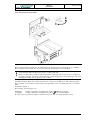
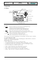
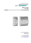
3.4.1 Program protection switch
Figure 4, Program protection switch
Before transferring any parameters to the DLX unit, the program protection switch must be set to “Enable”.
The program protection switch is located on the underside of the display board of the DLX.
!
Disconnect the supply voltage to the DLX before opening the enclosure. Otherwise an accidental pull
on the flat band cable can destroy the memory content of the unit.
Always touch first the grounded (earthed) metal frame of the unit with one hand to force equalization
of voltage potentials. Avoid any contact with other possibly charged parts of the data logger unit when
changing the setting of the program protection switch.
Housing for panel mounting: to achieve access to this switch, the front panel of the unit must be unscrewed
and flipped upwards. Please note that the front panel is connected to the CPU board with a flat band cable.
The program protection switch is located in the lower right hand corner of the DLX and can be operated by
hand.
19” rack: see Figure 4
The meaning of the inscriptions are:
Set Enable:
Setting of parameters is permitted, the symbol " " blinks in the display.
Set Disable:
Setting of parameters is disabled, the symbol " " is shown in the display.
To refuse access to parameter settings to unauthorized persons, the front panel should be sealed.
DLX
Page 14 of 76
User Manual
Bär Industrie-Elektronik GmbH / Lange Straße 87 / D-90762 Fürth / Phone +49 911 970590⋅Fax +49 911 9705950
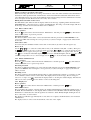
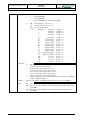
3.5 Pulse processing
Pulses
Momentary
value
Energy
Input 1..16
XIn1
The following registers {REG} are used for results : (see Appendix B)
For register addresses the following sub-addresses are possible:
ee = 01..16 Inputs 1..16
pp = 01..04 Total forwards 1..4 (positive)
nn = 01..04 Total backwards 1..4 (negative)
Energy registers cumulative
total
YIn1
100-ee
190-ee
current
last MP1
AT
Energy registers for current
total
XIn16
250-ee
YIn16
current
220-ee
last MP1
AT
101-ee
102-ee
103-ee
104-ee
191-ee
192-ee
193-ee
194-ee
rate 1
rate 2
rate 3
rate 4
current
last MP1
251-ee
252-ee
253-ee
254-ee
221-ee
222-ee
223-ee
224-ee
rate 1
rate 2
rate 3
rate 4
current
last MP1
REG{110-pp} = ( Σ ±REG{100-ee} ) cumulative
REG{260-pp} = ( Σ ±REG{100-ee} ) current
REG{100-ee} = IEee × REG{30000-ee} ⁄ REG{30100-ee}
REG{250-ee} = IEee × REG{30000-ee} ⁄ REG{30100-ee}
1
Pulses
29200-pp
Energy total
1…4
110-pp
200-pp
current
last MP1
+1
0
-1
Hysteresis: 29300-pp
60
MP1
230-pp
last MP1
AT
current
last MP1
AT
261-pp
262-pp
263-pp
264-pp
231-pp
232-pp
233-pp
234-pp
current
last MP1
AT
121-nn
122-nn
123-nn
124-nn
211-nn
212-nn
213-nn
214-nn
current
last MP1
271-pp
272-pp
273-pp
274-pp
241-pp
242-pp
243-pp
244-pp
1
+1
0
-1
Demand /
Increment
Input 1..16
260-pp
current
29200-pp
Registration period MP1
131-ee
161-ee
current
last MP1
MT
120-nn
210-nn
current
last MP1
201-pp
202-pp
203-pp
204-pp
111-pp
112-pp
113-pp
114-pp
rate 1
rate 2
rate 3
rate 4
IApp +
Momentary
value
Forward
rate 1
rate 2
rate 3
rate 4
Pulses
rate 1
rate 2
rate 3
rate 4
Pulse output
Pulse inputs
In1 to In16
IAnn -
Momentary
value
Backward
rate 1
rate 2
rate 3
rate 4
270-nn 240-nn
current
last MP1
AT
REG{120-nn} = ( Σ±REG{100-ee} ) cum.
current
last MP1
REG{270-nn} = ( Σ±REG{100-ee} ) curr.
Maximum demand
Total
300-ee
301-ee
rate 1
REG{131-ee} = {DIFFMP1} REG{100-ee} × 60 ⁄ MP1
rate 2
302-ee
REG{131-ee} = {DIFFMP1} REG{100-ee}
rate 3
303-ee
rate 4
304-ee
for demand
for increment
Value + Time
Demand /
Increment
Total 1..4
REG{141-pp} = ( Σ±REG{131-ee} )
+1
0
-1
141-pp
current
171-pp
last MP1
MT
Maxima
310-pp
Total
311-pp
rate 1
312-pp
rate 2
313-pp
rate 3
314-pp
rate 4
Value + Time
Forward
Maxima
Total
320-nn
rate 1
321-nn
rate 2
322-nn
rate 3
323-nn
rate 4
324-nn
Value + Time
Backward
Balance: 31000-04
+1
0
-1
132-ee
162-ee
current
last MP2
181-nn
last MP1
MT
REG{151-nn} = ( Σ±REG{131-ee} )
Registration period MP2
60
MP2
151-nn
current
REG{132-ee} = {DIFFMP2} REG{100-ee} × 60 ⁄ MP2
REG{132-ee} = {DIFFMP2} REG{100-ee}
for demand
for increment
REG{142-pp} = ( Σ±REG{132-ee} )
+1
0
-1
142-pp
172-pp
current
last MP2
152-nn
182-nn
current
last MP2
Balance: 31000-04
+1
0
-1
REG{152-nn} = ( Σ±REG{132-ee} )
Figure 5, Block circuit diagram of impulse processing
!
A calculation of values for registration period 2 only takes place if the parameter is set under the menu
item „Registration period“ in DLXPARA.
DLX
Page 15 of 76
User Manual
Bär Industrie-Elektronik GmbH / Lange Straße 87 / D-90762 Fürth / Phone +49 911 970590⋅Fax +49 911 9705950
3.5.1 Pulse inputs
Pulse inputs and control inputs are subject to signal verification implemented in the software, i.e. pulses that
fall short of a minimum period of time are not processed. This period can be programmed separately for
pulse length and pulse interval length in the range from 10ms to 2000ms in steps of 10 ms for all pulse inputs.
Incoming pulses are counted, multiplied with a programmable value between 1/1 and 99999999/99999999 (only
positive values possible) and added to the energy registers separated by rate (see figure 5, block circuit diagram of
pulse processing). Weighting to the correct physical measurement values is done with pulse multiplication factors
(these express the meter and transformer constants). The formula used is as follows:
X
W
=
Y R×K
X, Y
: Numerator and Divisor – no decimal places, 8 digits
W
: Transformer ratio
R
: Meter constant (e.g. Impulses/kWh)
K
: Reading constant (for optimized reading)
The transformer ratio is calculated as the ratio between primary and secondary voltages and currents.
Energy value weighting :
Transformer ratio : W = Uprim/Usec × Iprim/Isec
The reading constant usually has a value of 1 (reading in kWh or kvarh).
Example:
Voltage transformer:
Uprim/Usec = 110kV/100V = 1100
Current transformer:
Iprim/Isec = 300A/5A = 60
Meter constant:
R = 96000 Impulses/kWh
Reading constant:
K = 1
→ Transformer ratio:
W
→ Energy value weighting :
X
Y
= 1100 × 60 = 66000
=
66000
96000
=
66
96
=
11
16
The number of digits for energy register is set to 9 (Version 1.04.00 and higher). This includes digits to the left and
to the right of the decimal point (e.g. with one decimal place : 12345678.9). If an energy register exceeds the value
999999999, it continues at the value 000000000 and a flag will be set in the device status register (of that registration period).
All pulse inputs arrive in two separate energy registers and one pulse register:
• Cumulative register (settable), in which the meter reading of the supplying meter can be adjusted for control
and check purposes.
• Current (cannot be modified externally), which registers the flow of energy since the last reset.
• Pulse register (control register, cannot be modified externally), counts all incoming pulses from the related
input without weighting.
Furthermore the energy increment since the end of the last registration period is calculated for both registration periods (MP1 and MP2). By multiplication with the time factor, these values are converted into demand
values.
Demand value weighting : ZF =
60
Tm
ZF
: Time factor
Tm
: Registration period (in minutes)
The energy increment registers (and therefore also the demand registers) are reset to 0 at the beginning of
each new registration period.
Example:
Registration period:
MP1 = 15 min.
Time factor:
ZF = 60/15 = 4
Energy increment:
∆E = 25 kWh
→ Demand:
P
= ∆E × ZF = 100 kW
DLX
Page 16 of 76
User Manual
Bär Industrie-Elektronik GmbH / Lange Straße 87 / D-90762 Fürth / Phone +49 911 970590⋅Fax +49 911 9705950
3.5.2 Signal current input
A continuous signal current flow is applied to the signal current inputs (e.g. 0 .. 20mA, or 4 .. 20mA). This
current is proportional to the actual demand. By integration of the current over time (i.e. the measuring period) it is possible to calculate the energy consumed, from which the average demand is then calculated.
The signal current input (analogue input) measures power in order to establish energy consumption. The
power is measured over short intervals, multiplied by the time and the result is summated. This sum is
equivalent to the energy consumed. If the sum exceeds a fixed limit value "W", a 25msec internal output
pulse is triggered and "W" is subtracted from the sum. "W" is designated the pulse weighting and is set such
that at maximum demand a pulse frequency of 20Hz (pulse length: 25msec) is reached. The demand is measured via an external transducer that converts the measured demand to an injected current (selectable ranges: 0
to 20mA or 4 to 20mA).
Maximum current (:=20mA)
72000 pulses per hour (:=3600sec × 20)
X
DIF
=
Y 72000 × K
X, Y
: Numerator and Divisor – no decimal places, 8 digits
K
: Reading constant (for optimized reading)
DIF
: Transducer range (max. valueencoder - min. valueencoder) := 20Hz
The reading constant usually has a value of 1 (reading in kWh or kvarh).
Example:
Energy value weighting :
min. value:
0kW (corresponds to 0mA → 0Hz)
max. value:
3500kW (corresponds to 20mA → 20Hz)
→ Transducer range
Reading constant:
DIF = 3500 – 0 = 3500kWh
K = 1
→ Energy value weighting :
X
3500
35
7
=
=
=
Y
72000 720 144
3.5.3 Summation registers
The weighted pulses of all inputs can be totaled in up to 4 total registers (with positive or negative sign):
Totali = Σ kn × En
kn
: sign for input n, where: k = 1 or k = 0 or k = -1
En
: Energy value at input n, where n = 1 … 16
Depending on the sign, the incoming pulses are totaled in a positive or a negative register. In the case of a
simple sum (only positive inputs) the positive register contains the sum and the negative register contains the
value 0.
In the case of frequent changes of the direction of energy flow (e.g. between forward and backward), the
hysteresis (slack) can be used to activate the function “Differential total calculation” (for energy registers
only). Here pulses will only be added to the positive or negative energy registers once they have exceeded a
minimum amount of energy after a change of energy flow direction. The function of the hysteresis is one of
an intermediate storage register. Each pulse in positive direction will increase the value of that register,
whereas each pulse in negative direction will decrease its value. Pulses only appear at the output of the hysteresis register once its programmable maximum content is exceeded in either direction. An integrated energy
direction pointer ensures correct output to either “positive” or “negative” target registers. The purpose of the
hysteresis register is to prevent unnecessary totaling of pulses in the “positive” and “negative” registers,
when the flow of energy in both directions is almost in balance. A meaningful guideline for the content of the
hysteresis is double the sum of the absolute value of all weighted inputs of the related total register.
Example:
Total Energy
Forward (+)
Backward (-)
Result with
Hysteresis = 0 kWh
Hysteresis = 4 kWh
100 kWh
100 kWh
98 kWh
2 kWh
2 kWh
0 kWh
DLX
Page 17 of 76
User Manual
Bär Industrie-Elektronik GmbH / Lange Straße 87 / D-90762 Fürth / Phone +49 911 970590⋅Fax +49 911 9705950
In addition, the energy increment since the end of the last registration period is calculated for both the positive and negative registers of each sum and for each registration period (MP1 and MP2). If the function “balance calculation” is activated (possible only for demand or energy increment), then the difference between
the positive and negative total registers is calculated at the end of the registration period and only the result is
stored in the relevant register. This value is then multiplied with the time factor (ZF = 60/registration period
length), which results in the demand value. At the beginning of each new registration period, the energy
increment register (and therefore also the demand register) will be set to 0.
Example:
Demand
Forward (+)
Backward (-)
Result
Without
balance calculation
With
balance calculation
100 kW
100 kW
98 kW
2 kW
2 kW
0 kW
3.5.4 Pulse outputs
The individual energy totals can be weighted with a separate divisor (defined in kWh/impulse) and forwarded
to pulse outputs. Similar to the pulse inputs, the duration of pulse length and pulse interval can be programmed in the range from 10ms to 1000ms in steps of 10ms. A pulse output can buffer up to 255 pulses. As
soon as this value is exceeded, the unit sets the correlated error bit in the unit status. This error bit can only be
reset manually by the user. It is possible to link an output (Out1 to Out 4) on a software level to a particular
totaling unit. When this link for a pulse output is modified, the pulse buffer of that output is cleared.
Please note that when the function „Differential Total calculation“ is activated (Hysteresis > 0), the relation
between current demand and correlated pulses at the output can temporarily run out of synchronization because of buffered pulses.
3.5.5 Apparent demand and cos(ϕ
ϕ)
The DLX can calculate the apparent demand and the demand factor cos(ϕ) of any input and total registers.
One register each can be defined to hold the active or reactive demand, respectively:
Apparent demand = (reactive demand) 2 + (active demand) 2
cos (ϕ ) =
Active demand
Apparent demand
Up to two calculations of apparent demand and cos(ϕ) are possible. The results are available on the display
and can be stored in the periodic buffer (load profile memory). For the cos(ϕ) the display (and the stored
value) will always contain the first three decimals.
Example:
Active demand:
900 kW
Reactive demand:
120 kvar
→ Apparent demand:
907,965... kVA
→ Display of app. demand:
908 kVA
→ cos(ϕ):
0,99123...
→ Display of cos(ϕ):
991
3.5.6 Maximum demand calculation
At the end of each registration period, the unit compares the current demand value with the highest value
registered so far. If the new value is higher, then it will be stored together with date and time, separate for
each rate. This calculation only takes place for registration period MP1. Current maximum demand values
and register contents can be retrieved via remote data retrieval (currently only possible with SCTM protocol).
Starting from version 1.04.00, a maximum demand is also calculated without regard to rates (in addition to
the rate related values, and considering all days from 00:00 to 24:00).
Page 18 of 76
DLX
User Manual
Bär Industrie-Elektronik GmbH / Lange Straße 87 / D-90762 Fürth / Phone +49 911 970590⋅Fax +49 911 9705950
3.5.7 Maximum demand reset
With a maximum demand reset the values for maximum demand of registration period MP1 and the current
energy register values are transferred into the periodical buffer and then set to zero, to enable a new maximum demand calculation. In addition, the values of the cumulative energy registers will be stored.
The reset can be activated in three ways:
1) Via control input RSTX. The unit will execute the reset approx. 200ms after the change of the voltage level at
RSTX.
2) Via internal clock automatically once per day, week, month or year. The time can be selected without limitation.
3) Manually via the keypad (password protected).
All three methods can be enabled or disabled separately by means of setting the relevant parameters. Only
one reset is allowed for each registration period MP1. After a reset the next reset can be suppressed for a
maximum of 99 registration periods MP1 (so called reset blockage).
3.5.8 Periodical buffer (billing data)
Upon each reset, the DLX unit stores the maximum demand values, the energy increment since the last reset
(from the current energy registers) and the value of the cumulative energy registers at the time of the last
completed registration period MP1. These values are available on the display of the unit. The DLX will store
at least the values of the last 20 resets. Using remote data retrieval (currently only available for SCTM protocol), maximum demand values and register readings for the last 9 reset actions can be retrieved.
DLX
User Manual
Page 19 of 76
Bär Industrie-Elektronik GmbH / Lange Straße 87 / D-90762 Fürth / Phone +49 911 970590⋅Fax +49 911 9705950
3.6 Time basis
The registration and calculation of demand values has to happen in a defined time frame. In order to calculate
the correct tariff-related values, the internal real time clock must be programmed to the valid official time
(e.g. CET = Central European Time or CEST = Central European Summer Time).
3.6.1 Setting the real time clock
The integrated real time clock is buffered by a “GoldCap” capacitor, which provides power for a minimum of
7 days in the event of a power failure. Should the power failure last longer than the capacity of the GoldCap,
then the clock (the system time) will be set 59 minutes and 10 seconds after the date and time of the last
stored value of the main registration period MP1 once the power supply returns.
The time can be set via the keypad, via the service interface or by means of the SCTM message in the case of
remote data retrieval (if this feature was enabled during the setting of parameters). Please note that if summertime switching is activated, the clock cannot be set or synchronized during the time period of the “double” hour, due to the ambiguity of that period. During this period the unit will ignore the command. In order
to not affect time management, the clock should not be set via more than one interface at the same time.
3.6.2 Automatic summertime switching
The DLX unit can perform automatic summertime switching if so desired. The switching times (month
weekday, hour) can be programmed (set) in advance into a table.
Example:
Start of summertime:
last Sunday in March, switch from 2:00 to 3:00
Start of wintertime:
last Sunday in October, switch from 3:00 to 2:00
Please note that when using the table, both times must be programmed as standard time (CET = wintertime),
i.e. if the reverse switching from summer to winter shall take place at 03:00 summertime, the value must be
set as 02:00 in DLXPARA. After a unit reset, summertime switching is activated (factory setting).
3.6.3 Synchronization
The internal real time clock can be synchronized to the closest full minute via a freely programmable SYN
control input (any of Ctl1 to Ctl7). Currently two methods of synchronization are available:
•
Via external contact (e.g. external radio clock)
• Via DCF77 receiver module (type AWS0) from the company Meinberg (Germany)
In both cases the unit is synchronized to a full minute (seconds = 0). The permitted synchronization window
depends on a setting in DLXPARA:
•
SYN window = 0: Synchronization in a window of +/- 30 seconds around each full
minute; synchronization is always possible
•
SYN window > 0: Synchronization in a window of +/- x seconds (max. 29 seconds) around the end of
registration period MP1, any attempt to synchronize outside of the permitted time
window results in the generation (and storage) of an error event.
Example:
SYN window:
10 seconds
Registration period:
MP1 = 15 minutes
→ Synchronization only permitted in a window of +/- 10 seconds around each full 15 minutes
(where minutes = 0 or 15 or 30 or 45).
Page 20 of 76
DLX
User Manual
Bär Industrie-Elektronik GmbH / Lange Straße 87 / D-90762 Fürth / Phone +49 911 970590⋅Fax +49 911 9705950
3.6.4 Registration period
The registration period is the period of time used to calculate demand values (and energy increment values).
At the end of a registration period, the current value of the maximum demand registers will be stored. Subsequently the maximum demand registers will be set to zero. Two independent registration periods can be defined:
•
Registration period MP1: "Billing registration period" programmable in steps of 1, 2, 3, 4, 5, 6, 10, 12,
15, 20, 30 and 60 minutes.
•
Registration period MP2: programmable in steps of 1, 2, 3, 4, 5, 6, 10, 12, 15, 20, 30 and 60 minutes as
well as 2, 3, 6, 12 and 24 hours; if not required, this registration period can be disabled;
registration period MP2 can be programmed to the same value as MP1.
Calculation of maximum demand values and billing data (see page 17) only takes place for registration period MP1.
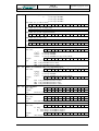
3.7 Rate dependent processing
The DLX can process up to 4 energy and maximum demand rates. Please note that there is a differentiation
between „number of rates“ (programmable) and “rate control” (settable).
With “rate control” one can select the method of switching between different rates. There are two alternatives:
1) The rate is determined by control inputs TR1, TR2, TR3 and TR4 (external rate control).
2) The rate is determined by the internal rate calendar.
The "number of rates" determines how many different rates the unit will differentiate and use. If the unit is
programmed to use less than 4 rates, then the limit used is the highest programmed rate. If, for example the
number of energy rates is programmed to 2, then the energy registration will only allow rates 1 and 2, even if
the rate calendar stipulates rate 4. In this case rate 2 would be used instead of rate 4.
Example:
Number of rates: 2
• AT1 (theoretical) → AT1 (in the unit)
• AT2 (theoretical) → AT2 (in the unit)
• AT3 (theoretical) → AT2 (in the unit) : Limited to the highest programmed rate
• AT4 (theoretical) → AT2 (in the unit) : Limited to the highest programmed rate
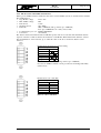
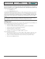
3.7.1 Rate control
The currently active rate can be determined either via the rate control inputs (e.g. radio clock, or ripple control receiver) or via the internal rate calendar. Both are queried all the time:
• AT: Changes have an immediate effect on the energy rate.
• MT: The current maximum demand rate is always determined 5 seconds before the end of the current
registration period and is then valid for this registration period (only one demand rate is possible
per registration period.
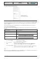
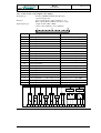
3.7.2 Rate calendar
The device has a rate calendar with a table for up to 100 public holidays. The internal rates can be transmitted
to external devices using the control outputs (Out1 to Out4 or Rel1 and Rel2), e.g. to control other devices.
The rate program (settable) is stored in the form of an internal rate calendar, which is hierarchically structured in three levels. The highest level defines the seasons, the second level defines the weekly programs and
the lowest level defines the daily rate tables with the switching times for rates.
The definition of seasons allows up to six periods within one year (e.g. summertime or wintertime) that can
have different rate structures.
DLX
Page 21 of 76
User Manual
Bär Industrie-Elektronik GmbH / Lange Straße 87 / D-90762 Fürth / Phone +49 911 970590⋅Fax +49 911 9705950
Example:
Season 1: from 01.03 00:00
to 01.10 00:00
Season 2: from 01.10 00:00
to 01.03 00:00 (default value in DLXPARA: 1 ---)
Each active season requires the definition of a weekly program, which assigns the relevant daily rate switching tables (1..15) to weekdays. This can be shown in a table as follows:
Season
1
2
3
4
5
6
Mo
1
2
Tu-Th
1
2
Fr
1
2
Weekdays
Sa
Su
1
1
2
2
PH1
1
2
PH2
1
2
PH3
1
2
In the table, weekdays are abbreviated as follows:
Mo = Monday
Tu-Th = Tuesday/Wednesday/Thursday
Fr = Friday
Sa = Saturday
So
= Sunday
PH1, 2, 3 = Public Holiday Type 1, 2, 3
The three types of public holidays (PH1, 2 or 3) allow you to define single weekdays to have special rates
that are set in a separate definition table. These public holidays have higher priority than normal weekdays
and allow one to consider holidays such as Easter, Christmas or other country specific holidays.
The sample entries in the above shown weekly program mean that in season 1 the daily rate table 1 shall be
used all the time and in season 2 the daily rate table 2 is valid. Of course, different daily rate tables can be
used for each weekday within a season, however only a maximum of 15 daily rate tables are available.
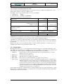
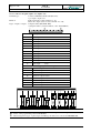
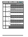
These daily rate tables define which energy rate and maximum demand rate shall be active at what time and
also which control outputs must be used to signal the rates to subsequent external devices. Each daily rate
table can have up to 16 rate switching times.
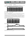
Example:
rate control for 4 energy rates and 2 maximum demand rates:
Switching times
Rates
from
To
Energy (AT)
Demand (MT)
06:00
10:00
AT2
MT2
10:00
12:00
AT3
MT2
12:00
13:00
AT4
MT2
13:00
16:00
AT3
MT2
16:00
22:00
AT2
MT2
22:00
06:00
AT1
MT1
This rate table relates to the following energy and demand rate curves:
Energy rate (AT):
4
3
2
1
00
02
04
06
08
10
12
14
16
18
20
22
00
Demand rate (MT):
4
3
2
1
00
02
04
06
08
10
12
14
16
18
20
22
00
The daily rate tables determine the rate curves that are used for different days within a year. These tables are
linked to seasons by means of the weekly programs.
DLX
Page 22 of 76
User Manual
Bär Industrie-Elektronik GmbH / Lange Straße 87 / D-90762 Fürth / Phone +49 911 970590⋅Fax +49 911 9705950
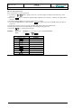
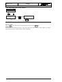
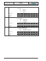
3.7.3 Rate control inputs
The rate control inputs TR1 to TR4 determine (if desired and if present in the customer specific hardware
configuration) the currently active energy rate and maximum demand rate. The usage of inputs and the correlation of input states to rates can be programmed freely (settable).
The factory default settings use TR1 to switch between two energy and demand rates.
TR1
TR2
TR3
TR4
Energy rate mask
Demand rate mask
TR1
0
1
TR2
-
TR3
-
TR4
-
Energy
AT1
AT2
Demand
MT1
MT2
Note: The state of deactivated control inputs (in our example: TR2, TR3 and TR4) has no influence on the
rate control (no matter whether the state is 0 = open or 1 = closed).
If other combinations are desired, they can be programmed (see user manual of DLXPARA).
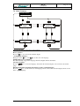
Example:
rate control for 4 energy rates and 2 demand rates, controlled by TR1, TR2 and TR3.
TR1
TR2
TR3
TR4
Energy rate mask
Demand rate mask
TR1
0
1
0
1
0
1
0
1
TR2
0
0
1
1
0
0
1
1
TR3
0
0
0
0
1
1
1
1
TR4
-
Energy
AT1
AT1
AT2
AT2
AT3
AT3
AT4
AT4
Demand
MT1
MT2
MT1
MT2
MT1
MT2
MT1
MT2
DLX
User Manual
Page 23 of 76
Bär Industrie-Elektronik GmbH / Lange Straße 87 / D-90762 Fürth / Phone +49 911 970590⋅Fax +49 911 9705950
3.8 Storage of measurements
3.8.1 Internal memory
All data that needs to be retained during a power failure, is stored in internal memory (Flash technology, non
volatile without backup battery, size of internal memory : 1MByte). These are all device parameters, registration period data (load profile data), spontaneous events and resets (billing data).
Each type of data uses a separate area of memory, which is administered separately. Memory is organized as
a circular buffer, i.e. once a particular storage area is full, the “oldest” information will be overwritten.
The registration period memory area can alternatively contain demand values, energy increments or cumulative counter values, positive and negative totals, apparent energy and cos(ϕ).
3.8.1.1 Unit restart (loading of factory default settings)
After a unit restart (message in the display (“Parameter Reset”) the complete internal memory (device parameters, spontaneous events, resets and registration period data) is erased and the standard parameters will
be loaded (see menu item “Factory settings”, page 66). A unit restart can be executed in the following ways:
•
Via the keypad: menu item „SET PARAMETERS – Factory settings”. This is password protected.
•
Via the programming software DLXPARA (using the service interface. This is password protected.
•
Via hardware reset: switch off the unit and place a jumper onto the pins labeled “Test” (located on the
CPU board under the display), then power up the unit and wait until the display shows “Parameter Reset”, then remove the jumper. This is protected by seals.
!
If parameters defining the buffer usage (number of counters, totals, digits, measurement types or storage allocation) are altered, the registration period buffer and the reset memory are erased automatically.
3.8.1.2 Unit warm start
The DLX unit performs a warm start (message in the display: “System warm start”) under the following
conditions:
•
On return of power supply after a power failure
•
When placing the “Reset” jumper on the CPU board.
Data device parameters and data remain intact. No data will be stored for registration periods during which
the power supply was absent. An event will be stored in the spontaneous event buffer for a unit warm start.
3.8.1.3 Unit cold start
The DLX unit performs a cold start (message in the display: “System cold start” under the same conditions as
above, if the internal RAM memory could not be buffered by the GoldCap (minimum of 7 days without
power supply voltage). In this case all device parameters and the device internal system time need to be reconfigured. All data in the registration period buffer is retained, and the system time is set to 59 minutes and
10 seconds after the timestamp of the last stored entry in the main registration period buffer. An event will be
stored in the spontaneous event buffer.
3.8.1.4 Erase memory
All internal memory (spontaneous events, resets and registration period data) can be erased using the menu
item „SET PARAMETERS – Erase memory“). The device parameters are retained.
An event is stored in the spontaneous event buffer.
3.8.2 Security mechanisms for data storage
All data is secured in a number of ways: when data is stored, each byte written is checked by an additional
read cycle; for each block of data a checksum is stored which is checked for correctness when the block is
read. Data is only used and forwarded when the checksums match.
DLX
Page 24 of 76
User Manual
Bär Industrie-Elektronik GmbH / Lange Straße 87 / D-90762 Fürth / Phone +49 911 970590⋅Fax +49 911 9705950
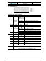
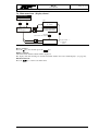
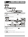
3.8.3 Block diagram of internal memory
Figure 6, Block diagram of internal memory
The internal registration period memory can be divided into two areas for registration periods MP1 and MP2
(if active), using DLXPARA. Each area can contain counter readings, energy increments or demand values
with 4, 6 or 8 digits.
Data stored in internal memory can additionally be stored on a PC-Card (backup memory, see page 63).
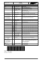
3.8.4 Capacity of internal memory
Depending on parameter settings (DLXPARA) the individual areas of internal memory have the following
capacity:
Device parameters:
1 set of parameters
Spontaneous events:
Min. 780
Resets (billing data):
Min. 20 (depends on the number of defined input channels and
totals)
Registration period MP1:
Min.
Registration period MP2:
Min.
No. of sectors in MP1 × 65522
12 + (No. of bytes in MP1 × No. of entries in MP1)
No. of sectors in MP2 × 65522
12 + (No. of bytes in MP2 × No. of entries in MP2)
where:
No. of bytes in MPx:
4:
for values with 4 stored digits
6:
for values with 6 or 8 stored digits
No. of sectors in
Round (memory share for MPx x 9)
MPx:
(depends on the parameters for internal memory shares in DLXPARA)
e.g. memory share for MP1 = 56% → No. of sectors in MP1 = 5.
No. of entries in MPx: 1..32
(depends on the parameters for storage allocation: number of inputs, totals,
apparent demand and cos(ϕ) in registration period MP1 or MP2)
Note:
Due to the composition of FLASH memory devices a minimum of sectors of 65536 Bytes each is allocated to
each area (the exception being the device parameters with 1 sector).
DLX
Page 25 of 76
User Manual
Bär Industrie-Elektronik GmbH / Lange Straße 87 / D-90762 Fürth / Phone +49 911 970590⋅Fax +49 911 9705950
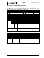
3.8.5 Capacity of backup memory (PC-Card)
Due to technological and administrational reasons the whole memory of a PC-Card is divided into sectors.
Data is always written or erased by complete sectors.
Depending on the card type the following sector sizes are available:
•
SRAM cards:
256Byte
• FLASH cards:
128kByte (:=131072Byte)
The memory is divided into the following areas:
Memory area
SRAM
FLASH
Administration information:
Number of Bytes (Sectors)
768 (3)
131072 (1)
Spontaneous events:
Number of Bytes (Sectors)
Number bytes per event
Number of events
1536 (6)
11
114 to 139
262144 (2)
11
11914 to 23831
Reset buffer:
(cumulative counters,
without rates)
Number of Bytes (Sectors)
9472 (37)
1538
4 to 6
262144 (2)
1538
83 to 170
Registration period MP1:
Registration period MP2:
Intermediate buffer:
Number of days
Programmed via DLXPARA
Number of days
Programmed via DLXPARA
Number of Bytes (Sectors)
0
131072 (1)
The number of stored entries per memory area varies depending on the level of usage in individual sectors.
DLXPARA can determine the required memory capacity of a PC-Card and this information can retrieved
from the unit via SCTM protocol (see appendix A: table addresses 700-80 and 700-81).
Checksums are created for each block of data to protect against corruption. The checksum is the arithmetic
sum total of a block of data and it uses one byte of memory. The amounts carried over from the summation
are discarded.
Each block of data can vary in length. For buffers one block of data is equivalent to one buffer entry. Administration information is also divided into blocks of data.
3.9 Control inputs
The DLX unit can have up to 7 control inputs (Ctl1..Ctl7). These inputs are by default of the S0 type (also
called IES), but optionally they are available in wipe technology (IEW). Control inputs are programmed and
activated by the software application DLXPARA. The following functions are available:
• SYN input:
Synchronization of the internal real time clock via external transmitters or external
DCF77 receiver (see page 62)
• RSTX input:
External maximum demand reset
• ANZ input:
External control for scrolling of the display
• TR1 to TR4:
Rate control via external transmitters (e.g. ripple control receivers)
• Log1 to Log4: Logic inputs that allow connection of the DLX with signal outputs of external devices.
With these inputs the user can create and log events that are relevant to the processing
of meter readings (e.g. defective transformers or external fault messages). The logic inputs are scanned every 10 seconds (second 5, 15, 25, 35, 45, 55). Incoming signals are
stored in the spontaneous events buffer together with date and time. They can additionally be stored (this needs to be enabled by DLXPARA) in the device status data of the
registration period area (L-bit, see appendix A).
Control inputs are subject to a signal detection in software similar to the one used for pulse inputs, i.e. pulses
that fall short of a minimum length are not considered. For control inputs the minimum pulse length and the
minimum pulse interval is set to 30ms.
DLX
Page 26 of 76
User Manual
Bär Industrie-Elektronik GmbH / Lange Straße 87 / D-90762 Fürth / Phone +49 911 970590⋅Fax +49 911 9705950
3.10 Outputs
The DLX data logger (remote metering device) can have up to 6 freely programmable outputs, which are
available in wipe technology (Out1 to Out4, type IAW) and as mechanical relays (Rel1 and Rel2). Corresponding light emitting diodes (LED) in the display show the state of each output (output closed or active:
LED is lit). The following functions are possible:
• Total 1 to 4:
pulse output for total registers (only with Out1 to Out4)
• MPA1 and 2:
output indicating the end of registration period MP1 or MP2
• RSTA:
reset output
• Alarm1 and 2: output for warning messages (Alarm1) and device faults (Alarm2)
• TRA1 to 4:
Rate control outputs. After a unit restart the following factory settings are active:
Energy rate
AT1
AT2
AT3
AT4
TRA1
0
1
0
1
TRA2
0
0
1
1
Demand rate
MT1
MT2
MT3
MT4
TRA3
0
1
0
1
TRA4
0
0
1
1
where: state "1": output is active (closed), output LED is lit.
• Log1 to 4:
logic outputs, used to forward signals to externally connected devices. Control of the
logic outputs is performed via remote data retrieval.
• In1 to 16:
pulse inputs can be redirected (1 to 1) to outputs (Version 1.04.00 and higher). No
conditioning of pulse lengths or signal type is performed.
These functions can allocated to more than one output at the same time (pulse multiplication).
3.11 Communication
The Data logger can communicate (for programming and for data retrieval) via three serial interfaces:
• Service interface
• Data interface
• Modem
The DLX currently supports two different protocols: SCTM and IEC60870 (see appendix A). An exact description of all interfaces is contained in section 8 Interfaces and section 9 Modem (Optional).
DLX
User Manual
Page 27 of 76
Bär Industrie-Elektronik GmbH / Lange Straße 87 / D-90762 Fürth / Phone +49 911 970590⋅Fax +49 911 9705950
4 Design
4.1 Sealing arrangements
4.1.1 Housing for panel mounting
The keypad can be sealed by two sealing screws in the upper left and lower right corner of the keypad. The
sealing wire needs to be fed through the whole in the enclosure and through the sealing screw and a seal
needs to be attached to the wire.
Sealing of the PC-Card cover or the terminal cover is done by means of a sealing screw and the splicing plate
of the PC-Card cover or the terminal cover. After placing and fixing the cover the sealing screw is fixed
through the whole in the splicing plate and then sealing wire needs to be fed through the holes in both the
splicing plate and the sealing screw and finally a seal is attached to the wire. Alternatively the PC-Card cover
can also be secured with a padlock (according to the VDEW requirement definition for electronic watt-hour
meters, Version 2.0).
Figure 7, Dimensions and sealing arrangements for covers
4.1.2 19” rack
Figure 8, Sealing arrangements for 19” rack
DLX
Page 28 of 76
User Manual
Bär Industrie-Elektronik GmbH / Lange Straße 87 / D-90762 Fürth / Phone +49 911 970590⋅Fax +49 911 9705950
Figure 9, Dimensions of 19” rack
4.2 Installation diagram
12
230
7
6
150
Figure 10, Dimensions of mounting points
6,3
20°
12,6
DLX
User Manual
Page 29 of 76
Bär Industrie-Elektronik GmbH / Lange Straße 87 / D-90762 Fürth / Phone +49 911 970590⋅Fax +49 911 9705950
5 Commissioning
5.1 Delivery state
PC Card slot:
no PC-Card inserted
Program protection switch: Programming enabled (switch position: "Set Enable")
Supply voltage:
as per order
5.2 Preparation for commissioning
1) Check the DLX unit for transport damages.
Should there be any damages caused by transport, please contact us.
2) Check that your DLX unit was delivered as per your order.
3) Read this user manual carefully before starting the commissioning.
4) Prepare all electrical connections according to the section “Terminals” (starting from page 30) or according to the accompanying special terminal connection plan. If a special terminal connection plan is present,
the section “Terminals” is invalid!
5) Install the DLX at the designated measurement location.
6) Connect the DLX to the mains supply voltage.
The DLX will start immediately with its operation, based on the factory settings as per section “Factory
settings” (see page 66).
7) Modify the measurement parameters and device parameters with the software application DLXPARA, if
required.
5.3 Supply voltage selection
The supply voltage of the DLX can be changed from 110/115VAC to 200/230VAC inside the device by
means of a sliding switch.
!
The supply voltage must only be changed when the DLX is without power!
Enclosure top
Proceed as follows:
Remove the four screws at the backside of the
DLX and lift the back plate off.
backplate
The switch for changing the supply voltage is
located on the PC-board mounted to the back
plate (see diagram to the left).
Toothed washer (4x)
Screw (4x)
Figure 11, Location of the switch
230V
115V
Figure 12, Voltage selection switch
Move the selector switch to the desired position
The selected voltage will be displayed on the
switch.
DLX
Page 30 of 76
User Manual
Bär Industrie-Elektronik GmbH / Lange Straße 87 / D-90762 Fürth / Phone +49 911 970590⋅Fax +49 911 9705950
5.4 Terminals
5.4.1 Location of the terminals
Figure 13, Location of the terminals (Housing for panel mounting)
Figure 14, Location of the terminals (19” rack)
5.4.2 Connector X1 (Supply voltage)
Type of connector:
Combicon MSTB2,5/3-ST-5,08 (Phoenix)
Function:
DLX mains power supply connector
Supply voltage:
100/115VAC or 200/230VAC; ca. 20VA
(Supply voltage selection see page 29)
Terminal
Description
1
Live (100/115VAC or 200/230VAC)
L1
2
Neutral
N
3
Protective Earth
PE
E lectronics
X1
Figure 15, Connector X1 (Supply voltage)
3
2
1
DLX
Page 31 of 76
User Manual
Bär Industrie-Elektronik GmbH / Lange Straße 87 / D-90762 Fürth / Phone +49 911 970590⋅Fax +49 911 9705950
5.4.3 Connector X2 (control inputs, relay outputs)
Terminal type:
Combicon MSTB2,5/10-ST-5,08 (Phoenix),
2 per In-/Output card
Function:
Control inputs (Ctl1 to Ctl7, terminal 1 to 14)
Relay outputs (Rel1 and Rel2, terminal 15 to 20)
Input/output types:
7 input modules (IES or IEW)
2 mech. relays (IAW me., max. 250V/2A)
Terminal Description
Function (default)
1
Control input Ctl1 -
SYN External Synchronization input
2
Control input Ctl1 +
3
Control input Ctl2-
4
Control input Ctl2+
5
Control input Ctl3-
6
Control input Ctl3+
7
Control input Ctl4-
8
Control input Ctl4+
9
Control input Ctl5-
10
Control input Ctl5+
11
Control input Ctl6-
12
Control input Ctl6+
13
Control input Ctl7-
14
Control input Ctl7+
15
Relay output Rel1
16
Relay output Rel1
feeder (uk)
17
Relay output Rel1
active contact (on, ak)
18
Relay output Rel2
19
Relay output Rel2
feeder (uk)
20
Relay output Rel2
active contact (on, ak)
RSTX External Reset
ANZ Scroll key
TR1 External rate control input 1
TR2 External rate control input 2
TR3 External rate control input 3
TR4 External rate control input 4
idle contact (off, rk) Alarm 2
idle contact (off, rk) Registration period output MPA1
Electronics
Alarm 2
SYN
ANZ
TR2
RSTX
X2
1
2
Figure 16, Connector X2
3
4
TR1
5
6
7
MPA 1
TR4
TR3
8
9
10
11
12
13
14
15
16
17
18
19
20
rk
uk
ak
rk
uk
ak
DLX
Page 32 of 76
User Manual
Bär Industrie-Elektronik GmbH / Lange Straße 87 / D-90762 Fürth / Phone +49 911 970590⋅Fax +49 911 9705950
5.4.4 Connector X3 (pulse inputs 1-6, outputs 1-4)
Terminal type:
Combicon MSTB2,5/10-ST-5,08 (Phoenix),
2 per input / output card
Function:
Pulse inputs (In1 to In6, terminal 1 to 12)
Electronic outputs (Out1 to Out4, terminal 13 to 20)
Types of inputs / outputs: 6 Input modules (IES, IEW, IED)
4 Output modules (solid state IAW el., max. 265V/100mA)
Terminal
Description
1
Pulse input
In1-
2
Pulse input
In1+
3
Pulse input
In2-
4
Pulse input
In2+
5
Pulse input
In3-
6
Pulse input
In3+
7
Pulse input
In4-
8
Pulse input
In4+
9
Pulse input
In5-
10
Pulse input
In5+
11
Pulse input
In6-
12
Pulse input
In6+
IN1
IN2
IN3
IN4
IN5
IN6
Freely programmable outputs
13
Electronic output Out1-
14
Electronic output Out1+
15
Electronic output Out2-
16
Electronic output Out2+
17
Electronic output Out3-
18
Electronic output Out3+
19
Electronic output Out4-
20
Electronic output Out4+
OUT1
OUT2
OUT3
OUT4
Electronics
Out1
IE1
IE3
IE2
X3
1
2
3
IE4
4
5
Out2
Out3
Out4
IE5
6
7
IE6
8
9
10
11
12
13
14
15
16
17
18
19
20
Figure 17, Connector X3
!
When IED (bi-current / bi-polar) Modules are used, then the signal conditioning must be adjusted by
means of the programming software DLXPARA.
When using mixed types of pulse inputs, the IES type modules are located at the left hand side.
DLX
Page 33 of 76
User Manual
Bär Industrie-Elektronik GmbH / Lange Straße 87 / D-90762 Fürth / Phone +49 911 970590⋅Fax +49 911 9705950
5.4.5 Connector X4 (pulse inputs 7-16)
Terminal type
Combicon MSTB2,5/10-ST-5,08 (Phoenix),
2 per input/output card
Function:
Pulse inputs (In7 to In16, terminal 1 to 20)
Input types:
10 input modules (IEW, IES, IED)
Terminal
Description
1
Pulse input
In7-
2
Pulse input
In7+
3
Pulse input
In8-
4
Pulse input
In8+
5
Pulse input
In9-
6
Pulse input
In9+
7
Pulse input
In10-
8
Pulse input
In10+
9
Pulse input
In11-
10
Pulse input
In11+
11
Pulse input
In12-
12
Pulse input
In12+
13
Pulse input
In13-
14
Pulse input
In13+
15
Pulse input
In14-
16
Pulse input
In14+
17
Pulse input
In15-
18
Pulse input
In15+
19
Pulse input
In16-
20
Pulse input
In16+
IN7
IN8
IN9
IN10
IN11
IN12
IN13
IN14
IN15
IN16
Electronics
IE7
IE9
IE11
IE8
X3
1
2
3
IE10
4
5
6
7
8
IE13
IE12
9
10
11
12
IE15
IE14
13
14
15
16
IE16
17
18
19
20
Figure 18, Connector X4
!
When IED (bi-current / bi-polar) modules are used, then the signal conditioning must be adjusted by
means of the programming software DLXPARA.
When using mixed types of pulse inputs, the IES type modules are located at the left hand side.
5.4.6 Connectors X5 and X6
X5 (modem interface): from page 61
X6 (data interface):
from page 58
Page 34 of 76
DLX
User Manual
Bär Industrie-Elektronik GmbH / Lange Straße 87 / D-90762 Fürth / Phone +49 911 970590⋅Fax +49 911 9705950
5.4.7 Input and output modules
Input and output modules convert the pulse types and voltage levels of commonly used signals in metering
technology into TTL signals used by the micro controller (and vice versa). At the same time these signals are
galvanically isolated from the process.
These types of input modules are available:
IES
Pulse input S0
S0 inputs are active inputs, i.e. they not only supply the transmitter with a signal voltage, but also
with an auxiliary voltage. S0 transmitters can contain their own electronic circuitry without the
need to have their own power supply. The relevant current and voltage limits are defined in DIN
43864. S0 inputs are capable to deliver 10mA to an 800Ω transmitter (to supply the transmitter)
and they still recognize a maximum current flow of 2.2mA as an “Off” signal. They are limited to
supplying a maximum voltage of 27V. Therefore S0 inputs are well suited for simple potential free
contacts and passive transmitters using optical couplers or transistors and they are frequently used
for control signals (synchronization, rate control, resets etc.)
IEW
Pulse inputs of type „wipe“
These inputs are passive inputs, i.e. they are supplied by the transmitter. A metering pulse is transmitted
directly as a voltage signal. In practice many different voltages and currents are used.
The input modules used can be operated with DC or AC signals from 24 to 265V. The maximum pulse
frequency is at 10Hz, current consumption is less than 10mA. Indefinite pulses (permanent contact) are
permitted. This makes IEW modules basically suitable for control signals.
IED
Pulse inputs of type „bi-current / bi-polar“
“Bi-current“ inputs are passive inputs, i.e. they are supplied by the pulse transmitter. As such they
are not linked to any voltage. „Bi-current“ pulses are DC voltage pulses of alternating polarity. A
pulse is recognized by the transgression of the 0V level. Instead of DC voltage pulses a permanent
DC voltage that changes its polarity for each pulse, can also be used. The standard voltage is 24V,
but it can vary from 19V to 60V. Our bi-current pulse inputs have an input current of less than
2mA at 24V. As each input pulse is represented by a change of polarity of the input voltage, our
IED modules internally produce a complete pulse of typically 20msec duration for each change of
polarity. This needs to be taken into consideration for the maximum pulse frequency (max. 20Hz).
If desired, IED modules with 90msec are available, which can be used up to 6Hz pulse frequency.
Bi-current transmission lines are highly immune to disturbances and should be used for long distance transmissions. Depending on the environment (neighboring lines, transmission distance) a
shielded cable of sufficient diameter should be used.
Note:
As each pulse is represented by a change of polarity, the signal condition must be
deactivated in DLXPARA.
Analogue Signal current input (analogue input)
A continuous signal current flow is applied to the signal current inputs (e.g. 0 .. 20mA, or 4 ..
20mA). This current is proportional to the actual demand. By integration of the current over time
(i.e. the measuring period) it is possible to calculate the energy consumed, from which the average
demand is then calculated. The signal current input (analogue input) measures power in order to
establish energy consumption. The power is measured over short intervals, multiplied by the time
and the result is summated. This sum is equivalent to the energy consumed. If the sum exceeds a
fixed limit value "W", a 25msec output pulse is triggered and "W" is subtracted from the sum. "W"
is designated the pulse weighting and is set such that at maximum demand a pulse frequency of
20Hz (pulse length: 25msec) is reached. The demand is measured via an external transducer that
converts the measured demand to an injected current (selectable ranges: 0 to 20mA or 4 to 20mA).
Note:
The signal condition must be deactivated in DLXPARA (minimal high phase,0:
10msec).
DLX
User Manual
Page 35 of 76
Bär Industrie-Elektronik GmbH / Lange Straße 87 / D-90762 Fürth / Phone +49 911 970590⋅Fax +49 911 9705950
The following types are used as output modules:
IAW el. Pulse output type „wipe“ (solid state, Out1 to Out4)
Electronic outputs of type wipe behave the same as relay contacts, i.e. they can carry a burden of
up to 265V and 100mA for AC or DC. They combine wear free switching with high switching frequency and are therefore ideal for high pulse frequencies. They can drive S0 inputs directly.
IAW me. Pulse output type „wipe“ (relay contacts, Rel1 and Rel2)
Mechanical relays are currently the only practical solution for the implementation of transmission
lines without auxiliary voltage. Similarly, only mechanical components are available for outputs
with change-over contacts (idle contact and active contact). Due to a life span of approx. 5 x 10⁵
they are not suitable for the transmission of pulses.
Electronic outputs (IAW el.) are generally less problematic.
DLX
Page 36 of 76
User Manual
Bär Industrie-Elektronik GmbH / Lange Straße 87 / D-90762 Fürth / Phone +49 911 970590⋅Fax +49 911 9705950
6 Operation
6.1 Display
LC-Display
Key "Cursor-up"
LED Alarm 1
LED Alarm 2
LED PC-Card
Key "ENTER"
Al1
Al2
EXIT
ENTER
M
Key "EXIT"
Ctl1
Ctl2
Ctl3
Ctl4
Ctl5
Ctl6
Ctl7
Rel1
Key "Cursor-down"
Rel2
Modem
In1
In2
In3
In4
In5
In6
Out1
Out2
Out3
Out4
In7
In8
In9
In10
In11
In12
In13
In14
In15
In16
Data
LED "Modem"
Service
LED "Data"
LED "Service"
3 rows of LEDs
Ctl1 to Ctl7, Rel1 and Rel2
Out1 to Out4, In1 to In16
Figure 19, Layout of operation controls and indicators
6.1.1 Keys
•
Moves the scroll list to the next value (in the standard display mode);
Activates the selected menu item (in menu mode);
Stores the previously set parameter values (in individual menus);
Moves the cursor one position to the right (in individual menus).
•
Exits from the current menu item without storing any parameter values.
• Up (
• Down (
)
Changes from the standard display mode into the menu item „Select language“;
Moves one menu item up or increases a value by one (+1).
) Activates the main menu (in standard display mode);
Moves one menu item down or decreases a value by one (-1).
After pressing any key the background illumination of the LC displays is activated for approx. 15 minutes.
6.1.2 Light emitting diodes (LED)
The LED’s show whether the DLX is receiving or transmitting pulses, whether faults have occurred and
whether the unit is currently using the PC-Card:
The light emitting diode(s)
• "In1" to „In16" represent the state of the corresponding pulse input.
• "Al1" blinks when an alarm of class1 (warning) has occurred (see „Fault displays“, page 67).
• "Al2" blinks when an alarm of class 2 (device fault) has occurred (see „Fault displays”, page 67).
• "M" is active during access to the PC-Card (memory card).
• "Out1" to "Out4" are lit when the corresponding output is closed (active).
• "Rel1" and "Rel2" show the current status of the corresponding relay..
• "Ctl1" to "Ctl7" show the current status of the corresponding control input.
• "Modem", "Data" and "Service" are lit during communication on these interfaces.
DLX
Page 37 of 76
User Manual
Bär Industrie-Elektronik GmbH / Lange Straße 87 / D-90762 Fürth / Phone +49 911 970590⋅Fax +49 911 9705950
6.1.3 Standard display mode
D DM ONYY H H: mm :s s
W t→A T x M T x T m X = Y Y→Z Z
← Line 1
← Line 2
← Line 3
← Line 4
Figure 20, Standard display mode
Interpretation of the standard display mode
Line
1
Digit
1 and 2
3 to 5
Information
Day
Month
Format
01 to 31
JAN, FEB, MAR,
APR, MAY, JUN,
JUL, AUG, SEP,
OCT, NOV, DEC
00 to 99
(no symbol)
6 and 7
8
Year
Summertime
Switching
9 to 11
12 to 14
15 and 16
17
18
Hour
Minute
Second
Reset block
PC-Card
00: to 23:
00: to 59:
00 to 59
(blinking)
(no symbol)
19
Synchronization
(blinking)
(no symbol)
M
20
Program prot.
Switch
(blinking)
2
1 to 3
Weekday
4 to 6
8 to 10
Energy rate
Demand rate
12 to 15
16 to 17
Registr. Period
Registr. Period
length
18
Unit of registr.
period
Time remaining
in registr. period
19 to 20
(blinking)
Mo to Su,
F1 to F3
AT1 to AT4
MT1 to MT4
MP1= or MP2=
1, 2, 3, 4, 5, 6, 10,
12, 15, 20, 30, 60,
2*, 3*, 6*, 12*, 24*
or h
ZZ
Explanation
Date display: Day
Date display: Month
Date display: Year
No switching between summertime and wintertime
Summertime
Wintertime
Hour display
Minute display
Second display
Reset not permitted
No PC-Card inserted or activated
PC-Card inserted and activated
PC-Card registered but not activated
Synchronization not programmed
Manual Synchronization (via terminal)
Synchronization via DCF77 receiver, DCF77 signal valid
No synchronization, DCF77 signal disturbed
Programming not permitted ("Set Disable")
Programming permitted ("Set Enable")
Weekday or public holiday (F1 to F3 from the rate calendar)
Name of the active energy rate
Name of the active demand rate
Registration period identifier
Length of registration period MP1 or MP2 in minutes or in
hours* (if a lowercase „h“ is shown in position 18)
Length of registration period MP1 or MP2 in minutes ( ) or .
in hours* (h).
Time remaining to the end of the registration period in minutes
or in hours (is a lowercase „h“ is shown in position 18)
3
1 to 20
Scroll list : text display
(if programmed via programming software DLXPARA)
4
1 to 20
Scroll list : text display
(if programmed via programming software DLXPARA)
During programming line 4 shows the text “Password is active!”
* only for registration period MP2
Page 38 of 76
DLX
User Manual
Bär Industrie-Elektronik GmbH / Lange Straße 87 / D-90762 Fürth / Phone +49 911 970590⋅Fax +49 911 9705950
7 Menus
7.1 Flow diagram
Figure 21, Flow diagram of menus
The menus
After powering up, the DLX shows the standard display (see page 37). Press
to go to the menu item „Select language“ (see page 41). Press
to go to the main menu (from page 43).
Press
to start the scroll list (if a scroll list has been programmed via DLXPARA) (see page 42).
DLX
User Manual
Page 39 of 76
Bär Industrie-Elektronik GmbH / Lange Straße 87 / D-90762 Fürth / Phone +49 911 970590⋅Fax +49 911 9705950
7.2 Legend of flow diagrams
The following symbols will be used in the next section:
Key on
DLX
Explanation
EXIT key
Exit current menu item, displayed settings are not stored in the DLX
ENTER key
Enter the selected menu item or store the displayed value in the DLX
ARROW UPWARDS key
Move up by one menu item or increase the selected value bye 1 (+1)
ARROW DOWNWARDS key
Move down by one menu item or decrease the selected value bye 1 (-1)
Arrow keys
Indicate the selected menu item and the direction to more menu items
Figure 22, Legend of flow diagrams
7.3 Password input
d
Parameters : Factory settings
Clear memory
Maintenance: Set time, activate and
deactivate PC-Card, Set counters, Reset
Increase value
Back to first digit
Decrease value
Move to next digit
d
Increase value
Decrease value
Move to next digit
d
Enter the menu item
Figure 23, Flow diagram for password input
Several menu items („Set Parameters“: Factory Settings (unit restart) and Clear Memory, as well as “Maintenance”: Set Time, Activate PC-Card, Deactivate PC-Card, Set Counters, Initiate Reset) require a password
for their activation. The following passwords are supported:
•
PARAMETERS: for the protection of parameters (when programming via DLXPARA) and for activation of other menu items in the menus „Maintenance“ and „Set Parameters“ except for a unit restart. The
default password is 00000001
•
SET (Menu "Maintenance"): to protect the unit against unauthorized alterations of time and counter
settings, the default password is 00000002
•
PC-CARD (Menu "Maintenance"): in order to activate and deactivate a PC-Card, the default password is
00000003
•
FACT. SETTINGS (unit restart, Menu "Set Parameters"): to clear the entire memory and load the factory default settings, the default password is 00000004
•
RESET (Menu "Maintenance"): to initiate a maximum demand reset via the keypad, the default password is 00000005
Leading zeros can be ignored when using DLXPARA. The default passwords can only be modified using
DLXPARA.
DLX
Page 40 of 76
User Manual
Bär Industrie-Elektronik GmbH / Lange Straße 87 / D-90762 Fürth / Phone +49 911 970590⋅Fax +49 911 9705950
How to enter a password
Proceed as follows to enter a password:
1) Use the keys
or
until the display shows the correct first digit (a number between 0 and 9) of the
password.
2) Press the
key to confirm the digit. It will be replaced by an asterisk (∗) and the next digit will be
selected.
3) For the remaining digits proceed as described under 1) and 2).
4) Once the last digit has been selected and the
key has been pressed, the DLX checks the entered
password.
5) If the password was entered correctly, the DLX will activate the relevant menu item..
6) If the password was incorrect, input returns to the first digit of the password.
7) Press the
key to cancel password input.
Example:
Password:
Input:
00000001 (you can enter 1 only, if using DLXPARA)
7×
,1× ,
Input/ Key
Starting point
Figure 24, Entering a password
Display
00000000
∗0000000
∗∗000000
∗∗∗00000
∗∗∗∗0000
∗∗∗∗∗000
∗∗∗∗∗∗00
∗∗∗∗∗∗∗0
∗∗∗∗∗∗∗1
Relevant menu
DLX
User Manual
Page 41 of 76
Bär Industrie-Elektronik GmbH / Lange Straße 87 / D-90762 Fürth / Phone +49 911 970590⋅Fax +49 911 9705950
7.4 Select language
Figure 25, Flow diagram for menu item „Select Language“
How to get there
Press the
key once when in the standard display.
„Scrolling“ the languages
Each press of the
key or the
key scrolls to the next language.
Which languages are available ?
The DLX currently supports the languages German, English, French and Dutch.
Selecting a language
Press the
key to select the language. Afterwards the standard display is shown in the selected language.
Exit the menu without changing the language (back to standard display)
Press the
key to exit the menu. No new language will be selected. The standard display will be shown
in the original language.
DLX
Page 42 of 76
User Manual
Bär Industrie-Elektronik GmbH / Lange Straße 87 / D-90762 Fürth / Phone +49 911 970590⋅Fax +49 911 9705950
7.5 Scroll list
Until end of scroll list
last scroll list entry
5th scroll list entry
1st scroll list entry
2nd scroll list entry
3rd scroll list entry
4th scroll list entry
Figure 26, Flow diagram for the scroll list
Selecting the scroll list (if programmed)
The first entry of the scroll list is always shown in line 3 and 4 of the standard display.
Press the
key to show the second entry of the scroll list in the display.
Scrolling the list
There are three ways to scroll through the list:
1) Manual scrolling by pressing the
key:
key shows the next entry of the scroll list in the display. When there are no
Each press on the
further entries in the list, the display returns to the first entry.
2) Automatic scrolling of the list based on a time delay:
In order to activate automatic scrolling of the scroll list, the delay (in seconds) determining the time period for which each entry is displayed, must be stipulated in the programming software. Once this time is
set, the display will scroll automatically (from the time the parameters are programmed into the unit).
Each press of the
key interrupts (and resets) the time delay and moves the display to the next entry. After the delay time has elapsed, automatic scrolling will be resumed.
3) Scrolling by means of the ANZ control input:
Each activation of the ANZ control input activates the next entry of the scroll list in the display. Once the
list is exhausted, the display returns to the first entry.
Other key functions:
key:
if no scroll list was programmed, pressing the
key has no function (other than
activating the display illumination).
- and
keys:
these keys have their usual function during the display of the scroll list (i.e. the
key
displays the Select Language menu and the
key enters the main menu).
Content of the scroll list
Programming of the scroll list can only be done with the programming software DLXPARA. An entry into
the scroll list consists of the scroll list entry text, the related value and a physical unit:
• Line 3 shows the freely programmable text (max. 20 characters)
• Line 4 shows the related value (selected by address) and the programmable unit (5 characters)
Example:
Standard display
E n e r g y - T r a n s 1 1 - H T
0 0 1 7 3 1 1 5
k W h
Input in DLXPARA:
"Energy-Trans11-HT"
Text:
Unit:
"kWh"
DLX
Page 43 of 76
User Manual
Bär Industrie-Elektronik GmbH ⋅ Lange Straße 87 ⋅ D-90762 Fürth ⋅ Telefon 0911/97059-0 ⋅ Telefax +49 911 9705950
7.6 Main menu item „Display alarms”
either
-- Display Alarms --No alarms
-----Main menu-----Display alarms ?
Info ?
Set Parameters ?
-- Display Alarms --xxxxxxxxxxxxxxxxxxxx
xxxxxxxxxxxxxxxxxxxx
or
Next alarm
(until all alarms were displayed)
-- Display Alarms --no further
alarms
Figure 27, Flow diagram for alarm display
How to get there
Press the
key once and then press the
key.
Display of alarms
All occurred and undeleted alarms will be displayed.
The displays and their meaning are described in further detail in the section "Fault displays" (see page 67).
Exit the menu item
key to return to the main menu.
Press the
Page 44 of 76
DLX
User Manual
Bär Industrie-Elektronik GmbH ⋅ Lange Straße 87 ⋅ D-90762 Fürth ⋅ Telefon 0911/97059-0 ⋅ Telefax +49 911 9705950
7.7 Main menu item „Info“
How to get there
Press the
key twice when in the standard display and then press the
key.
What does the display show ?
The display will show the current values (cumulative and current energy, demand and pulses), the measurement values from the registration period (MP1 or MP2: energy values, increments or demand values) as well
as resets (billing data), spontaneous events, table addresses and information about the current firmware version. It is possible to show all values stored in internal memory (load profiles and billing data) in the display.
All values are displayed with 4, 6 or 8 digits and their correct physical units (depending on the parameters set
with DLXPARA). Starting from Version 1.04.00 one or two decimal places are possible.
Item selection
Use the keys on the front panel to select the required value from the internal memory via its parameters:
key :
moves to the next parameter, after the last parameter moves to the first parameters (this
corresponds to a key).
key :
returns to the original menu.
key :
increases the selected parameter to the next higher possible value.
key :
decreases the selected parameter to the next lower possible value.
One digit of the selected parameter blinks in the display. On each change of the parameters the measurement
display will be updated.
If no value is available for the selected parameters, then automatically the next valid entry from the registration period buffer will be displayed. This is an easy method to request the oldest or newest load profile entry:
modify the input field for the year with the
or the
key until there are no further changes of the display:
the display now shows the oldest load profile entry (after using the
key) or the newest load profile entry
(after using the
key).
Invalid values or values incompatible with memory entries cannot be requested.
When displaying energy or demand values from the load profile memory, the unit always shows the total
value (not rate related) together with the active energy and demand rate valid at the end of the registration
period (you cannot edit the rate).
When displaying billing data, the values are shown depending on the rate, which can be selected. Each entry
can only be selected by the secondary reset index (0..99), the primary reset index (1..12, settable) will be
displayed automatically.
The unit differentiates between counters (Z01 to Z06), totals (S01+ to S04-), apparent demand (X01 and
X02) and cos(ϕ) (P01+ to P02-): only the values programmed for the corresponding registration period will
be displayed.
The physical unit displayed must be programmed with DLXPARA.
Display on entry
When entering the menu item the display first shows the newest complete registration period or the last set of
billing data. The cursor (blinking) points to the first character of the first parameter. If the memory is empty,
the display will show “No data available”.
DLX
Page 45 of 76
User Manual
Bär Industrie-Elektronik GmbH ⋅ Lange Straße 87 ⋅ D-90762 Fürth ⋅ Telefon 0911/97059-0 ⋅ Telefax +49 911 9705950
7.7.1 Current values
---CURRENT VALUES--EN-CUM MP1 TOT Z01
CURR: 00000000 kWh
LAST: 00000000 kWh
---CURRENT VALUES--EN-CUM MP1 TOT Z02
CURR: 00000000 kWh
LAST: 00000000 kWh
---CURRENT VALUES--EN-CUM MP1 TOT Z01
CURR: 00000000 kWh
LAST: 00000000 kWh
---CURRENT VALUES--EN-CUM MP1 AT1 Z01
CURR: 00000000 kWh
LAST: 00000000 kWh
Use the arrow keys to
select the desired
counter
To select the counter
To select the rate
Press twice
Press
Use the arrow keys to
select the desired rate
to proceed
---CURRENT VALUES--EN-CUM MP1 TOT Z01
CURR: 00000000 kWh
LAST: 00000000 kWh
---CURRENT VALUES--EN-CUM MP2 TOT Z01
CURR: 00000000 kWh
LAST: 00000000 kWh
---CURRENT VALUES--EN-CUM MP1 TOT Z01
CURR: 00000000 kWh
LAST: 00000000 kWh
---CURRENT VALUES--EN-CURR MP1 TOT Z01
CURR: 00000000 kWh
LAST: 00000000 kWh
Choose between
energy and demand
---CURRENT VALUES--PULSES MP1
Z01
CURR: 00000000
---CURRENT VALUES--DEMAND MP1
Z01
CURR: 00000000 kW
LAST: 00000000 kW
To select the registration period
-----Main menu-----Display alarms ?
Info ?
Set Parameters ?
-------INFO--------Current values ?
Energy values ?
Load profile ?
Press
to proceed
Press
to proceed
Figure 28, Flow diagram for menu item “Info” (current values)
How to get there
Press the
-key while in menu “Info”. The DLX enters the menu item selected (displays and arrow on
each side).
Changing the parameters
The
or
keys can be used to select energy, demand or pulse values, to select the registration period, the
rate, the counter or to select a total value.
What will be shown ?
The display will show the cumulative (settable) and the current (not settable) energy values as well as the
demand values of the DLX for the current and the previous (last) registration period MP1 or MP2 (if present)
for all counters (Z) and totals (S) stored in that registration period.
For the pulse values all pulses recorded since the start of measurement (unweighted) will be shown for all
counters (Z01 to Z16), as well as all pulses forwarded to outputs from totals (S01 to S04).
DLX
Page 46 of 76
User Manual
Bär Industrie-Elektronik GmbH ⋅ Lange Straße 87 ⋅ D-90762 Fürth ⋅ Telefon 0911/97059-0 ⋅ Telefax +49 911 9705950
7.7.2 Energy values
-----Main menu-----Display alarms ?
Info ?
Set Parameters ?
-------INFO--------Current values ?
Energy values ?
Load profile ?
---ENERGY VALUES---No parameters are
set for registration
period MP2 !
---ENERGY VALUES---No parameters are
set for registration
period MP1 !
-------INFO--------Current values ?
Energy values ?
Load profile ?
---ENERGY VALUES---DDMONYYYY hh:mm
MP1 Gsxx ATx Z01
WWWWWWWW
EEEEE
---ENERGY VALUES---DDMONYYYY hh:mm
MP1 Gsxx ATx Z01
WWWWWWWW
EEEEE
Day Month Year
Hour
Minute
---ENERGY VALUES---DDMONYYYY hh:mm
MP1 Gsxx ATx Z01
WWWWWWWW
EEEEE
----ENERGY VALUES--DDMMMYYYY hh:mm
MP
Gsxx
ATx Z
WWWWWWWW
EEEEE
Registration period Value
Unit
Counter
---ENERGY VALUES---DDMONYYYY hh:mm
MP1 Gsxx ATx Z01
WWWWWWWW
EEEEE
---ENERGY VALUES---DDMONYYYY hh:mm
MP1 Gsxx ATx Z01
WWWWWWWW
EEEEE
---ENERGY VALUES---DDMONYYYY hh:mm
MP1 Gsxx ATx Z01
WWWWWWWW
EEEEE
---ENERGY VALUES---DDMONYYYY hh:mm
MP1 Gsxx ATx Z01
WWWWWWWW
EEEEE
Figure 29, Flow diagram for menu item „Info“ (energy values)
How to get there
Press the
key once when in menu “Info” and then press the
key. The DLX enters the menu item
selected.
Changing the parameters
The
or
keys can be used to select the registration period (MP1 or MP2), the counter, the date and time
and to select apparent energy or cos(ϕ).
What will be shown ?
After entering the menu item the DLX will display the energy values of the last registration period MP1 or
MP2 (if present) for all counters (Z01 to Z16), totals (S01 to S04), apparent demand (X01 or X02) and cos(ϕ)
that have been stored. It will also show the device status (Gs, see appendix A, SCTM Addresses).
Use the -key or the -key to switch between registration periods.
Use the
-key to move the cursor to the next parameter, then use the
or the
key to change the
parameter value.
DLX
Page 47 of 76
User Manual
Bär Industrie-Elektronik GmbH ⋅ Lange Straße 87 ⋅ D-90762 Fürth ⋅ Telefon 0911/97059-0 ⋅ Telefax +49 911 9705950
7.7.3 Load profiles
-----Main menu-----Display alarms ?
Info ?
Set Parameters ?
-------INFO--------Current values ?
Energy values ?
Load profile ?
---LOAD PROFILES---No parameters are
set for registration
period MP2 !
---LOAD PROFILES---No parameters are
set for registration
period MP1 !
-------INFO--------Current values ?
Energy values ?
Load profile ?
---LOAD PROFILES---DDMONYYYY hh:mm
MP1 Gsxx MTx Z01
WWWWWWWW
EEEEE
---LOAD PROFILES---DDMONYYYY hh:mm
MP1 Gsxx MTx Z01
WWWWWWWW
EEEEE
Day Month Year
Hour
Minute
---LOAD PROFILES---DDMONYYYY hh:mm
MP1 Gsxx MTx Z01
WWWWWWWW
EEEEE
----LOAD PROFILES--DDMMMYYYY hh:mm
MP
Gsxx
MTx Z
WWWWWWWW
EEEEE
Registration period Value
Unit
Counter
---LOAD PROFILES---DDMONYYYY hh:mm
MP1 Gsxx MTx Z01
WWWWWWWW
EEEEE
---LOAD PROFILES---DDMONYYYY hh:mm
MP1 Gsxx MTx Z01
WWWWWWWW
EEEEE
---LOAD PROFILES---DDMONYYYY hh:mm
MP1 Gsxx MTx Z01
WWWWWWWW
EEEEE
---LOAD PROFILES---DDMONYYYY hh:mm
MP1 Gsxx MTx Z01
WWWWWWWW
EEEEE
Figure 30, Flow diagram for menu item „Info“ (load profile values)
How to get there
Press the
key twice when in menu “Info” and then press the
key. The DLX enters the menu item
selected.
Changing the parameters
The
or
keys can be used to select the registration period (MP1 or MP2), the counter, the date and time
and to select apparent energy or cos(ϕ).
What will be shown ?
After entering the menu item the DLX will display the load profile values (demand values or increments) of
the last registration period MP1 or MP2 (if present) for all counters (Z01 to Z16), totals (S01 to S04), apparent demand (X01 or X02) and cos(ϕ) (P01 or P02) that have been stored. Load profile values that have rolled
over (exceeded the maximum value of the register) are indicated by a leading FF, e.g. a value of 18000 is
shown as FFFF8000 (if 4 digits have been programmed for this value) (see buffer options in DLXPARA
manual). Values for periods of a power failure are shown as “--------“.
Use the -key or the -key to switch between registration periods. Use the
-key to move the cursor
or the
key to change the parameter value.
to the next parameter, then use the
DLX
Page 48 of 76
User Manual
Bär Industrie-Elektronik GmbH ⋅ Lange Straße 87 ⋅ D-90762 Fürth ⋅ Telefon 0911/97059-0 ⋅ Telefax +49 911 9705950
7.7.4 Billing data
Press twice
-----Main menu-----Display alarms ?
Info ?
Set Parameters ?
-------INFO--------Current values ?
Energy values ?
Load profile ?
Press three times
-------INFO--------Energy values ?
Load profile ?
Billing data ?
-BD:CURRENT
R DDMMMYYYY
RST.
WWWWWWWW
Value
Reset Counter
(settable 1..12)
---BILLING DATA----Energy current ?
Energy cumulat.?
Maximum demand ?
-BD: URRENT ENERGY —R DDMMMYYYY hh:mm
RST. /
AT Z
WWWWWWWW
EEEEE
ENERGY-hh:mm
AT
Z
EEEEE
-BD: CURRENT ENERGY —R DDMMMYYYY hh:mm
RST. /
AT Z
WWWWWWWW
EEEEE
Energy rate
Unit
(internal 0…99)
Counter
Reset Counter
---BILLING DATA----Energy current ?
Energy cumulat.?
Maximum demand ?
-BD:CUMULAT. ENERGYR DDMMMYYYY hh:mm
RST.
AT
Z
WWWWWWWW
EEEEE
Value
Reset Counter
Reset Counter
(settable 1..12)
(internal 0…99)
-BD: CUMULAT. ENERGY R DDMMMYYYY hh:mm
RST. /
AT Z
WWWWWWWW
EEEEE
---BILLING DATA----Energy current ?
Energy cumulat.?
Maximum demand ?
Value
Reset Counter
Reset Counter
(settable 1..12)
(internal 0…99)
DEMAND-hh:mm
MT
Z
EEEEE
Energy rate
Unit
Counter
-BD: CUMULAT. ENERGY R DDMMMYYYY hh:mm
RST. /
AT Z
WWWWWWWW
EEEEE
-BD: CUMULAT. ENERGY R DDMMMYYYY hh:mm
RST. /
AT Z
WWWWWWWW
EEEEE
Energy rate
Unit
Counter
-BD:MAXIMUM
M DDMMMYYYY
RST.
WWWWWWWW
-BD: CURRENT ENERGY—R DDMMMYYYY hh:mm
RST. /
AT Z
WWWWWWWW
EEEEE
-BD: MAXIMUM DEMAND—M DDMMMYYYY hh:mm
RST. /
MT Z
WWWWWWWW
EEEEE
-BD: MAXIMUM DEMAND—M DDMMMYYYY hh:mm
RST. /
MT Z
WWWWWWWW
EEEEE
-BD: MAXIMUM DEMAND—M DDMMMYYYY hh:mm
RST. /
MT Z
WWWWWWWW
EEEEE
Figure 31, Flow diagram for menu item „Info” (billing data)
How to get there
Press the
key three times when in menu “Info” and then press the
key. The DLX enters the menu
item selected (the one surrounded by two arrows). There will be three submenu items:
• current energy
• cumulative energy
• Maximum demand
7.7.4.1 Energy current
How to select „energy current”
-key when in menu item „Info: Billing data“. The submenu item will be activated.
Press the
Changing the Parameters
DLX
User Manual
Page 49 of 76
Bär Industrie-Elektronik GmbH ⋅ Lange Straße 87 ⋅ D-90762 Fürth ⋅ Telefon 0911/97059-0 ⋅ Telefax +49 911 9705950
The
or
keys can be used to select values for the internal reset counter, the energy rate, the counter or
the total register. The date shown (the date and time of the reset) will be adjusted automatically.
What will be shown ?
The display will show the current energy values for all counters and totals as of the date and time of the
maximum demand reset. You can use the
or the
key to select the desired reset index.
7.7.4.2 Energy Cumulative
How to get there
Press the
key once when in menu item „Info: Billing data“ and then the
key. The submenu item
will be activated.
Changing the parameters
or
keys can be used to select values for the internal reset counter, the energy rate, the counter or
The
the total register. The date shown (the date and time of the reset) will be adjusted automatically.
What will be shown ?
The display will show the cumulative energy values (also called meter readings) for all counters and totals as
of the date and time of the maximum demand reset. You can use the
or the
key to select the desired
reset index.
7.7.4.3 Maximum demand
How to get there
key twice when in menu item „Info: Billing data“ and then the
key. The submenu item
Press the
will be activated.
Changing the parameters
The
or
keys can be used to select values for the internal reset counter, the energy rate, the counter or
the total register. The date shown (the date and time of the maximum) will be adjusted automatically.
What will be shown ?
The display will show the maximum demand values for all counters and totals as of the date and time of the
maximum demand reset. You can use the
or the
key to select the desired reset index.
DLX
Page 50 of 76
User Manual
Bär Industrie-Elektronik GmbH ⋅ Lange Straße 87 ⋅ D-90762 Fürth ⋅ Telefon 0911/97059-0 ⋅ Telefax +49 911 9705950
7.7.5 Spontaneous events
Press twice
-----Main menu-----Display alarms ?
Info ?
Set Parameters ?
-------INFO--------Current values ?
Energy values ?
Load profile ?
Press four times
-------INFO--------Load profile ?
Billing Data ?
Spontaneous events ?
-SPONTANEOUS EVENTS
No.:
0000
Date: DDMMMYYYY hh:mm
Event: 00/00
Use the and keys as well as the
key to display all the different
spontaneous events.
Figure 32, Flow diagram for the menu item „Info“ (spontaneous events)
How to get there
Press the
key four times when in menu “Info” and then press the
key. The DLX enters the menu
item selected.
What will be shown ?
The DLX will show the spontaneous events on the display. For more information see "Fault displays" on
page 67.
Example:
Explanation:
No:
sequential number
- S P O N T A N E O U S - E V E N T S Date:
date
and time of occurrence
N o . :
0 0 0 0 1
Message:
see
page
67
D a t e :
0 1 A P R 9 9
1 1 : 5 0
e.g.:
03/01:
power
failure
M e s s a g e :
0 3 / 0 1
+
The sign behind the event identifier shows whether the fault or error has occurred (“+”: = event occurred/activated) or was erased (“-“: = event was erased or fault was removed).
7.7.6 Table address
Press twice
-----Main menu-----Display alarms ?
Info ?
Set Parameters ?
-------INFO--------Current values ?
Energy values ?
Load profile ?
Press five times
-------INFO--------Billing Data ?
Spontaneous events ?
Table addresses ?
--TABLE ADDRESSES—
Adr.:00000 Index:00
^
00000
Use the and keys to adjust the
digits. Use the
key to confirm a
digit and move to the next digit.
spontaneous events.
Figure 33, Flow diagram for menu item „Info“ (table addresses)
How to get there
Press the
key five times when in menu “Info” and then press the
key. The DLX enters the menu
item selected.
Changing the parameters
The
or
keys can be used to select values for address and the index.
What will be shown ?
DLX will show the selected table addresses on the display. For more information see appendix B.
Example:
- - - T A B L E - - A D D R E S S - - A d r . : 1 0 0 0 0
I n d e x : 0 1
1 4 3 2
Explanation:
Adr.: desired table address;
see appendix B
1432: value in DLX memory
DLX
Page 51 of 76
User Manual
Bär Industrie-Elektronik GmbH ⋅ Lange Straße 87 ⋅ D-90762 Fürth ⋅ Telefon 0911/97059-0 ⋅ Telefax +49 911 9705950
7.7.7 Version
Press twice
-----Main menu-----Display alarms ?
Info ?
Set Parameters ?
-------INFO--------Current values ?
Energy values ?
Load profile ?
Press six times
-------INFO--------Spontaneous events ?
Table addresses ?
Version ?
_-----VERSION-----Ver. X.XX.XX
Date: MON DD YYYY
Checksum : XXXXXXXX
Figure 34, Flow diagram for menu item „Info“ (version)
How to get there
key six times when in menu “Info” and then press the
key. The DLX enters the menu
Press the
item selected.
What will be shown ?
The DLX will show the firmware version, the release date and the checksum of the firmware.
7.8 Main menu item „Set Parameters“
--SYSTEM RESTART---System restart is
being executed.
Press three times
-----Main menu-----Display alarms ?
Info ?
Set Parameters ?
--SET PARAMETERS---Factory settings ?
Erase memory ?
--SYSTEM RESTART---Reset all parameters
to factory values ?
YES = Enter
--SYSTEM RESTART---------PASSWORD-----00000000
^
Use the and keys to adjust the
digits. Use the
key to confirm a
digit and move to the next digit.
spontaneous events.
--SET PARAMETERS---Factory settings ?
Clear memory ?
----CLEAR MEMORY---------PASSWORD-----00000000
^
----CLEAR MEMORY---All data in internal
memory is being
erased!
----CLEAR MEMORY---Erase all data in
Internal memory ?
YES = Enter
Figure 35, Flow diagram for menu „Set Parameters“
How to get there
Press the
key three times when in standard display and then press the
You can now select between submenu items:
•
Factory settings
•
Clear memory
key.
7.8.1 Factory settings (unit restart or system restart)
How to get there
Press the
-key when in menu item “Set Parameters”. The function “Factory settings” is protected by a
password and can only be selected when programming is enabled (program protection switch is in position
“Set Enable”, see page 13).
Page 52 of 76
DLX
User Manual
Bär Industrie-Elektronik GmbH ⋅ Lange Straße 87 ⋅ D-90762 Fürth ⋅ Telefon 0911/97059-0 ⋅ Telefax +49 911 9705950
Password protection
The function „System Restart“ can be activated with the password for FACT. SETTINGS . After entering the
correct password (see „Password input“ on page 39) the function will be executed.
What is going to happen?
The function „Unit restart/System restart“ will set all parameters to the factory settings (see page 66), clear
the internal memory and erase the internal clock.
Execution of a system restart
After entering the password the display will show the safety question „Reset all parameters to factory settings
?”. Press the
key to confirm. The DLX unit will now check the state of the program protection switch
(see page 13). Only if the switch is in position “Set Enable” will a system restart be executed. If you press the
key, no system restart will be executed.
If the program protection switch is in position "Set Disable" (programming blocked, secured certification
mode), the message “programming disabled” will be displayed. The DLX will exit the menu item without
executing a system restart.
Once a system restart has been activated correctly, the display will show the message “System restart is being
executed”. When the system restart is complete, the LCD will show the standard display.
!
Once a system restart has been activated, it cannot be cancelled.
7.8.2 Erase memory
How to get there
key when in menu item “Set Parameters” and then the
key. The function “Erase
Press the
memory” is protected by a password and can only be selected when programming is enabled (program
protection switch is in position “Set Enable”, see page 13).
Password protection
The function „Erase memory“ can be activated with the password for PARAMETERS . After entering the
correct password (see „Password input“ on page 39) the function will be executed.
What is going to happen ?
The function „Erase memory“ clears all of the internal memory:
•
Registration period memory for MP1 and MP2 (load profiles)
•
Spontaneous event buffer
• Resets and billing data
If the values stored so far in memory need to be processed further elsewhere, then they need to be retrieved
by adequate means from the data logger.
Execution of the function „Clear memory“
After entering the password the display will show the safety question „Clear all data in internal memory ?”.
Press the
key to confirm. The DLX unit will now check the state of the program protection switch
(see page 13). Only if the switch is in position “Set Enable” will the memory be erased. If you press the
key, the memory will not be erased..
If the program protection switch is in position "Set Disable" (programming blocked, secured certification
mode), the message “programming disabled” will be displayed. The DLX will exit the menu item without
erasing the memory.
Once the function has been activated correctly, the display will show the message “All data in internal memory is being erased”. When all data has been erased, the LCD will show the standard display.
!
Once the function “Clear memory” has been activated, it cannot be cancelled.
DLX
Page 53 of 76
User Manual
Bär Industrie-Elektronik GmbH ⋅ Lange Straße 87 ⋅ D-90762 Fürth ⋅ Telefon 0911/97059-0 ⋅ Telefax +49 911 9705950
7.9 Main menu item „Maintenance“
Press four times
-----Main menu-----Info ?
Set Parameters ?
Maintenance ?
----Maintenance----Set Time ?
Activate PC-Card ?
Deactivate PC-Card
-----Set Time ----DD.MMM.YYYY hh:mm
^
Use the and keys to adjust the
digits. Use the
key to confirm a
digit and move to the next digit.
spontaneous events.
Pressing the
key on the last
digit will set the time in the unit.
--Activate PC-Card-PC-Card is being
activated …
----Maintenance----Set Time ?
Activate PC-Card?
Deactivate PC-Card
--Activate PC-Card-PC-Card is already
activated !
-Deactivate PC-CardPC-Card is being
deactivated …
----Maintenance----Set Time ?
Activate PC-Card?
Deactivate PC-Card
-Deactivate PC-CardPC-Card was not
activated !
----Maintenance----Activate PC-Card?
Deactivate PC-Card
Set Counters ?
----Set Counters---Counter : Z
Rate :
Value : 00000000 Wh
----Set Counters---Counter : Z
Rate :
TOT
Value : 00000000 Wh
Use the and keys to adjust
the digits. Use the
key to
confirm a digit and move to the
next digit.
Pressing the
key on the
last digit will set the value in the
unit.
---Initiate Reset--Maximum reset is
still blocked!
----Maintenance----Deactivate PC-Card
Set Counters ?
Initiate Reset ?
----Set Counters---Counter : Z
Rate :
Value : 0000000 Wh
---Initiate Reset--Maximum reset has
been initiated!
Automatically back to
standard display
----Maintenance----Set Counters ?
Initiate Reset ?
Display Test ?
Inclusive of all LEDs
Automatically back to
main menu.
Figure 36, Flow diagram for menu item „Maintenance“
How to get there
Press the
key four times when in standard display then press the
six additional sub menu items:
• Set Time
• Activate PC-Card
• Deactivate PC-Card
• Enter counter values
• Initiate maximum reset
• Display test
key. Now you can choose one of
Page 54 of 76
DLX
User Manual
Bär Industrie-Elektronik GmbH ⋅ Lange Straße 87 ⋅ D-90762 Fürth ⋅ Telefon 0911/97059-0 ⋅ Telefax +49 911 9705950
7.9.1 Set time
How to get there
Press the
-key when in menu item “Maintenance”. The function „Set time“ is password protected.
Password protection
The function „Set time“ can be activated with either the password for PARAMETERS or the password for
SET. After entering the correct password (see „Password input“ on page 39) the function will be executed.
What can be done ?
You can set the date and time of the internal real time clock of the DLX unit.
Setting the time
You can set the day (DD), the month (MMM), the year (YYYY), the hour (hh) and the minute (mm), one
after the other. Use the and
keys to change the selected value (increase or decrease). Use the
key to confirm your input and to move to the next value.
Press
key after setting the minute value to set the time into the DLC unit. The value for the seconds
will be set to zero.
Press the
key to exit the function and to return to the menu item „Maintenance“ without altering the
date and time of the unit.
7.9.2 Register PC-Card
How to get there
Press the -key once when in menu item “Maintenance” and then press the
key. The function "Register PC-Card " is password protected.
Password protection
The function „Register PC-Card“ can be activated with either the password for PARAMETERS or the password for PC-CARD. After entering the correct password (see „Password input“ on page 39) the function will
be executed.
Why do you have to activate a PC-Card ?
If you do not activate the PC-Card, the DLX unit cannot write to the PC-Card. By activating the PC-Card the
virtual interface between the DLX unit and the PC-Card will be activated and the PC-Card will be prepared
for data storage.
During the activation of a PC-Card..
The display will first show the message „Card will be erased on first activation. Continue = ENTER”. Press
the
key to confirm the formatting of the PC-Card. The LED labeled “M” will be lit and the display
will show the message “PC-Card is being activated… DO NOT REMOVE !!“. Once the formatting is complete, the display will show the message „Card is ready for recording DO NOT REMOVE !!“ and the LED
labeled „M“ will go out.
If the PC-Card cannot be activated, a corresponding message will be show, such as:
• Card is not present Please insert again AT ONCE!!
• Card is write protected Please UNLOCK!!
• Wrong card type Try ANOTHER card!!
In this state the LC display will blink with a one second frequency.
7.9.3 Deactivate PC-Card
How to get there
Press the -key twice when in menu item “Maintenance” and then press the
key. The function "Deactivate PC-Card " is password protected.
Password protection
The function „Deactivate PC-Card“ can be activated with either the password for PARAMETERS or the
password for PC-CARD. After entering the correct password (see „Password input“ on page 39) the function
will be executed.
DLX
User Manual
Page 55 of 76
Bär Industrie-Elektronik GmbH ⋅ Lange Straße 87 ⋅ D-90762 Fürth ⋅ Telefon 0911/97059-0 ⋅ Telefax +49 911 9705950
Why do you have to deactivate a PC-Card ?
When deactivating a PC-Card, the recording of information on the card will be terminated, the administration
information will be updated and the virtual interface between the DLX unit and the PC-Card will be deactivated. If the PC-Card is removed from the DLX unit without deactivating it, then the administration information is incomplete and the PC-Card cannot be read by other software.
During the deactivation of a PC-Card..
The LED labeled „M“ will be lit and the display will show the message „Updating admin. Information DO
NOT REMOVE!!“. Once this action is complete, the LED labeled „M“ will go out and the display will show
the message „Card has been deactivated. Please remove NOW!!“.
7.9.4 Enter counter values
How to get there
Press the -key three times when in menu item “Maintenance” and then press the
key. The function
"Enter counter values" is password protected.
Password protection
The function „Enter counter values“ can be activated with either the password for PARAMETERS or the
password for SET. After entering the correct password (see „Password input“ on page 39) the function will
be executed.
What can be done?
You can modify the cumulative initial counter value for all counters (Z) and for all total registers (S).
How to do it
Use the and
keys to select the counter (Z01 to Z16) or the summation unit (S01 + to S04-). Then press
the
key to move the cursor to the rate selection. Use the
and
keys to select the desired rate (rate
1 to 4 or the rateless register). Now press the
key to move the cursor to the register value. Use the
and
keys to modify the individual digits (9 digits for version 1.04.00 and higher) and the
key to
confirm your input and to move to the next digit. Use the
key to abort the function at any stage.
7.9.5 Initiate maximum reset
How to get there
Press the -key four times when in menu item “Maintenance” and then press the
key. The function
"Initiate maximum reset" is password protected.
Password protection
The function „Initiate maximum reset“ can be activated with either the password for PARAMETERS or the
password for RESET. After entering the correct password (see „Password input“ on page 39) the function
will be executed.
Executing a reset
The function will store the maximum demand values (together with the date and time of occurrence) as well
as the cumulative and the current counter values. The display will show the message „Reset is being executed.” for a couple of seconds. Afterwards the display returns to showing the standard display. The first line
will now show the symbol " " for the duration of the reset blocking time.
7.9.6 Display test
How to get there
Press the -key five times when in menu item “Maintenance” and then press the
key.
What will be tested ?
The test includes all segments of the LC display, the background illumination and all light emitting diodes of
the DLX. First the illumination of the display will be switched off and all LEDs will be lit. Then the display
illumination is switched back on and all segments are switched to black. Finally all light emitting diodes are
lit for a short time, one after another.
The display test will take approximately 10 seconds. Once it is complete, the DLX returns to the menu item
“Maintenance”
The display test has no effect on the measurement or the state of the outputs.
DLX
Page 56 of 76
User Manual
Bär Industrie-Elektronik GmbH ⋅ Lange Straße 87 ⋅ D-90762 Fürth ⋅ Telefon 0911/97059-0 ⋅ Telefax +49 911 9705950
7.10 Main menu item „Erase Alarms“
EXIT
-----Main menu-----Set Parameters ?
Maintenance ?
Erase alarms ?
ENTER
----Erase alarms----Erase alarms ?
EXIT
ENTER
All alarms will be cleared
Figure 37, Flow diagram for menu item „Erase alarms“
How to get there
Press the
key five times when in standard display and the press the
key.
Erasing alarms
The user can erase all alarms that have occurred. Possibly active alarm indication relays will be reset and the
light emitting diodes for alarm indication will stop blinking.
DLX
User Manual
Page 57 of 76
Bär Industrie-Elektronik GmbH ⋅ Lange Straße 87 ⋅ D-90762 Fürth ⋅ Telefon 0911/97059-0 ⋅ Telefax +49 911 9705950
8 Interfaces
8.1 General
Three interfaces are available in the DLX unit:
• Service interface for programming purposes and data retrieval
• Data interface for data retrieval on site (optional)
• Modem interface for remote data retrieval (optional)
8.1.1 Automatic protocol recognition:
The DLX unit automatically recognizes the retrieval protocol (currently SCTM, IEC60870 or the programming software DLXPARA). On both direct interfaces (service interface and data interface) the first query
telegram will be lost in the case of a protocol change (the modem interface can change the protocol without
losing a telegram). Therefore DLXPARA can be used to define the default protocol for the data interface (the
default protocol for the service interface is always the IE60870 protocol). The DLX unit will switch to the
default protocol after each programming activity and after 5 minutes with no communication on the relevant
interface.
!
Due to safety reasons the programming software can only communicate with the service interface.
8.2 Service interface
The service interface is used to program the DLX unit and to retrieve data with a fixed baud rate (9600 baud).
It is implemented as a 25 pin SUB-D connector (female) according to ISO2110, the pin allocation is according to V.24/RS232C/DIN 66020.
Programming of the DLX is done using the programming software DLXPARA.
Please read the user manual of the programming software DLXPARA for instructions on programming.
Figure 38, Service interface
8.2.1 Pin allocation of the SUB-D (female) service interface RS232
DLX (25 pins, female)
cable
PC (25 pins, male)
Input/Output Pin No.
Pin No. Input/Output Standard usage
Input
Output
TxD
(transmit data)
2
2
Output
Input
RxD
(receive data)
3
3
Input
Output
RTS
(request to send)
4
4
Output
Input
CTS
(clear to send)
5
5
Output
Input
DSR
(data set ready)
6
6
GND (protective earth)
7
7
Input
Output
DTR
(data terminal ready)
20
20
8.2.2 Connection PC/Laptop ↔ Service interface
For the connection between a DLX and a PC, a programming cable or modem cable (#6998) is required.
Plug the programming cable into a free COM port of the PC/Laptop and into the service interface of the DLX.
Now you can start the required software (programming or data retrieval).
DLX
Page 58 of 76
User Manual
Bär Industrie-Elektronik GmbH ⋅ Lange Straße 87 ⋅ D-90762 Fürth ⋅ Telefon 0911/97059-0 ⋅ Telefax +49 911 9705950
8.3 Data interface (optional, X6)
The optional data interface can be used for data retrieval on site with data retrieval software (e.g. SIGLON)
or to connect to an external modem. The baud rate can be set with DLXPARA to a value between 300 and
9600 baud. It is implemented as a 25 pin SUB-D connector (female) according to ISO2110, the pin allocation
is according to V.24/RS232C/DIN 66020. Alternatively a 25 pin SUB-D male connector, a bus interface (MBus or RS485) or a LWL connector (fiber optic transmission connection) can be used.
8.3.1 Pin allocation of the data interface RS232 SUB-D (female)
The standard pin allocation of the data interface is identical with the service interface. For the connection
between the DLX and a PC, a modem cable is required. For the connection between a DLX and an external
modem a so-called null modem cable (crossed wires) is required.
8.3.2 Pin allocation of the data interface RS232 SUB-D (male)
For the connection between the DLX and a PC, a null modem cable (crossed wires) is required. For the connection between a DLX and an external modem a modem cable is required.
DLX (25 pins, male)
cable
PC (25 pins, male)
Input/Output Pin No.
Pin No. Input/Output Standard usage
Output
Output
TxD
(transmit data)
2
2
Input
Input
RxD
(receive data)
3
3
Output
Output
RTS
(request to send)
4
4
Input
Input
CTS
(clear to send)
5
5
GND (protective earth)
7
7
Input
Input
DSR
(data set ready)
6
6
Output
Output
DTR
(data terminal ready)
20
20
8.3.3 Pin allocation of the data interface RS232 (X6 at 19” rack)
For the connection between the DLX and a PC, a special cable (5 wires) is required.
Identification: Phoenix 5 pins PSC 1,5/5-M.
DLX (5 pins, male)
Input/Output Pin No.
Input
1
Input
2
Output
3
Output
4
5
Baud rate: 300 to 9600 Baud
cable
Pin No.
4
2
3
5
7
PC (25 pins, male)
Input/Output Standard usage
Output
RTS
Output
TxD
Input
RxD
Input
CTS
GND
DLX
User Manual
Page 59 of 76
Bär Industrie-Elektronik GmbH ⋅ Lange Straße 87 ⋅ D-90762 Fürth ⋅ Telefon 0911/97059-0 ⋅ Telefax +49 911 9705950
8.3.4 Pin allocation of the M-Bus data interface
With a passive M-Bus interface module the unit can be used in a M-Bus system, as described in the standard
TC 176/N17 Part 3:
• Typ. M-Bus voltage:
24V to 42V
• Max. M-Bus voltage:
50V
• Idle current:
< 2mA
• Working current:
10 to 20mA
• Baud rate:
300 to 2400 Baud (with good lines up to 4800 Bud)
Note: up to 9600 Baud at 19” rack (connector X6)
• Communication protocol: SCTM or IEC60870
• Connection:
via terminals
The distance between the DLX and the next M-Bus repeater unit can exceed 5 km. The maximum distance
depends on the line conditions and the current burden on the M-Bus. With sufficient line diameter, twisted
lines and limitations on the baud rate, up to double the value of the above mentioned distance can be
achieved.
Pin allocation at housing for panel mounting:
DLX (5 pins, male)
Function
Pin No.
M-Bus
1
M-Bus
2
—
3
Bridge to 1
4
Bridge to 2
5
Baud rate: 300 to 2400 Baud (with good lines up to 4800 Bud)
Note: the two M-Bus terminals 1 and 2 present twice and bridged internally
(with 4 and 5)
Pin allocation at 19” rack (X6):
DLX (5 pins, male)
Function
Pin No.
—
1
M-Bus
2
M-Bus
3
—
4
—
5
Baud rate: 300 to 9600 Baud
Page 60 of 76
DLX
User Manual
Bär Industrie-Elektronik GmbH ⋅ Lange Straße 87 ⋅ D-90762 Fürth ⋅ Telefon 0911/97059-0 ⋅ Telefax +49 911 9705950
8.3.5 Pin allocation of the fiber optic connector
Using the fiber optic connector (for fiber optic transmission), the unit can be read via 820nm optical fiber.
Figure 39, Fiber optic connector
• Wave length:
820nm (fiber optic interface from Hewlett Packard)
• Transmitter (TD):
transmits light
• Receiver (RD):
receives light
• Cable code:
A – 100/140µm
• Connection code:
W – SMA connector
• Baud rate:
300 to 9600 Baud
• Communication protocol: SCTM or IEC60870
•
Note: The idle condition of the fiber optic transmission line has to be configured with the jumpers between
the two connector elements:
• Idle condition „Light off“:
the jumper must be placed on pins 1/2 (delivery condition)
• Idle condition „Light on“:
the jumper must be placed on pins 2/3
The upper row of pins determines the condition of the receiver, the lower row of pins sets the condition for
the transmitter. Jumpers must be placed in both rows!
DLX
User Manual
Page 61 of 76
Bär Industrie-Elektronik GmbH ⋅ Lange Straße 87 ⋅ D-90762 Fürth ⋅ Telefon 0911/97059-0 ⋅ Telefax +49 911 9705950
9 Modem (Optional)
The DLX can be optionally equipped with an internal modem:
• Type: L834 (PSTN modem LGO 834) at housing for panel mounting
MOD (PSTN modem UniMod) at 19” rack
The modem works according to CCITT recommendations and supports the following modes:
• V.21 – Full duplex, 300 Baud
• V.22 – Full duplex, 1200 Baud
• V.22bis – Full duplex, 1200 and 2400 Baud
• V32 – Full duplex: 4800, 7200 and 9600 Baud
• V32bis – Full duplex: 4800, 7200, 9600 and 14400 Baud
9.1 Default settings for the integrated modem
On delivery of the DLX the following settings are active for the modem LGM832:
• &F0
Load factory setting 0
• S0=1
Respond after one ring
• &D0
Ignore DTR
• \N3
Auto-Reliable-Mode with error correction according to V.42/MNP4 and data compression
according to V.42bis/MNP5.
Note: If you use an older modem without error correction at your PC, then it is recommended to use the setting \N0 (normal mode, no error correction), as this will shorten the
time required to establish a connection.
• Q1
No feedback messages
• &W0&W1 Save user settings in non-volatile memory
The modem will respond after the first detected ring (S0=1). The transmission speed between the modems
will be adjusted automatically (\N3 or \N0). These settings are stipulated in DLXPARA as the modem initialization string and can be adjusted at any time.
For more detailed information please consult the manual shipped with the modem.
9.2 Modem interface (X5)
9.2.1 Pin allocation of the modem interface
The connection between the modem interface and a telephone line uses a telephone cable of type RJ12 with a
connector of type TAE6N.
Figure 40, Pin allocation of the telephone cable
In areas with high probability of lightning additional protection needs to be installed. For more information
please consult the manual shipped with the modem.
DLX
Page 62 of 76
User Manual
Bär Industrie-Elektronik GmbH ⋅ Lange Straße 87 ⋅ D-90762 Fürth ⋅ Telefon 0911/97059-0 ⋅ Telefax +49 911 9705950
10 DCF77 receiver (Option)
The DLX can be optionally equipped with a receiver for the signals transmitted by the long wave transmitter
DCF77 (time codes). The type used must the DCF77 aerial/receiver unit AWS0 from the company Meinberg
Funkuhren (Germany). The receiver module requires a +12VDC auxiliary voltage and it can be connected to
a S0 control input of the DLX.
Figure 41, DCF77 receiver module AWS0
10.1 Function
Synchronization of the time to full minutes (seconds = 0), no setting of the time! Prior to using the unit, the
time must have been set to within 30 seconds via the main menu item „Maintenance – Set time“ or by means
of the programming software DLXPARA.
10.2 Setting the parameters for the receiver module
Activate the item “Synchronization via external radio clock” in the menu item “Parameters – Time” in
DLXPARA and allocate the used control input in the menu item “Control Inputs” to the “SYN” function.
!
You must not allocate more than one control input to the SYN function!
The display of the data logger will show the corresponding symbol when the receiver module is active: " ".
10.3 Commissioning
10.3.1 Connection
Co-ax. cable:
Shield to
Wire to
SYN- (Ctl-)
SYN+ (Ctl+)
terminal,
terminal.
10.3.2 Alignment of the receiver module
The receiver module must be aligned to show its long side to the transmitter, which is located in Frankfurt/Main in central Germany.
Minimum distances
min. 1m to computers and monitors
min. 30cm to steel girders, metal plates and other metallic devices.
Checking the alignment
The modulation LED in the aerial enclosure of the AWS0 needs to blink once per second. The corresponding
LED on the DLX (for the control input SYN) needs to blink in the same rhythm. Rotate the receiver module
slowly and select an alignment roughly at the center of the area with good signal reception. If you have good
reception , the DLX display will show a static symbol " " latest after 3 minutes. A blinking symbol " "
indicates disrupted radio clock signal reception.
DLX
User Manual
Page 63 of 76
Bär Industrie-Elektronik GmbH ⋅ Lange Straße 87 ⋅ D-90762 Fürth ⋅ Telefon 0911/97059-0 ⋅ Telefax +49 911 9705950
11 PC-Card
11.1 Permitted PC-Card's
•
Standard:
JEIDA/PCMCIA
•
Type:
SRAM battery backed
Flash Memory-Card (AMD, D Series)
•
Capacity:
up to 4MByte
11.2 Treatment advice for PC-Cards
!
Noncompliance with the following advice can lead to destruction of the PC-Card.
• Do not bend or fold the PC-Card or subject it to similar conditions.
• Do not drop the PC-Card.
• Always keep the PC-Card dry and free of dust.
• Do not expose the PC-Card to high temperature or high humidity.
• To avoid static charges, always store the PC-Card in its original packing when it is not in use.
• Do not touch the connections of the PC-Card.
• Never use force when inserting a PC-Card. Only insert the card into slots designed for them.
• Do not remove the PC-Card from the unit until it has been deactivated.
11.3 Inserting a PC-Card
Figure 42, Inserting a PC-Card
Please ensure that you always insert the side of the PC-Card with the connector into the PC-Card slot. Also
ensure that the guiding grooves on the card match those of the slot, as shown in the above picture. The PCCard is guided in the slot by two guide rails that prevent the card from twisting. Slide the card into the slot
and press carefully until the PC-Card reaches the final position (PC-Card and ejection button are aligned, see
arrow ).
!
After inserting the PC-Card it needs to be activated by the DLX in order to use it for storage purposes.
The display will show the symbol " " in position 18 of line 1 after the card has been inserted and successfully
activated by the DLX unit.
If the card is not activated by the unit, the symbol will blink and the display will show the message “PC Card
is not activated!”.
DLX
Page 64 of 76
User Manual
Bär Industrie-Elektronik GmbH ⋅ Lange Straße 87 ⋅ D-90762 Fürth ⋅ Telefon 0911/97059-0 ⋅ Telefax +49 911 9705950
11.4 Activating a PC-Card
Use the menu item „Activate PC-Card“ (see page 54) to activate a PC-Card. After activation the symbol " "
will appear in the first line of the LC display.
Activation includes the following actions:
1) The DLX determines type and capacity of the PC-Card.
2) The DLX checks whether the capacity of the card is sufficient for the programmed number of counters
and days for the registration period buffer.
3) Once the PC-Card has been found to be suitable, it will be formatted to ensure that recording always takes
place on an empty PC-Card.
4) Afterwards the administration information will be stored on the PC-Card.
11.5 Deactivating a PC-Card
A PC-Card needs to be deactivated before it may be removed from the DLX. The deactivation updates the
administration information on the PC-Card. Use the menu item “Deactivate PC-Card” (see page 54) to deactivate a PC-Card. Once this is done, the symbol " " disappears from the first line of the LC display.
11.6 Removing a PC-Card
Press the eject button
move the card.
!
(see Figure 42, Inserting a PC-Card) on the right hand side of the PC-Card to re-
Only after deactivation via the keypad (see menu item "Deactivate PC-Card" page 54) the PC-Card
may be removed from the PC-Card slot.
If the PC-Card is removed from the DLX without prior deactivation, it cannot be read by other processing software! The " " symbol starts to blink and a corresponding alarm message will be created.
11.7 Data storage on a PC-Card
The following information will always automatically be stored on a PC-Card (independent from the program
parameters of the unit):
Spontaneous events:
the PC-Card will always contain at least the last 100 events.
Billing data:
the PC-Card will always contain at least cumulative rateless counter values of the
last 4 reset instances.
By default (if nothing else was programmed with DLXPARA) the demand values of counters 1 through to 16
for registration period MP1 will be stored for the last 35 days. The PC-Card will be used as a circular buffer,
i.e. once the buffer is full, the newest incoming value overwrites the oldest value.
You can use the programming software to activate storage of data for registration period MP2. In addition,
you can select which values shall be stored and what the storage depth in days will be. For more information
see page 25.
!
The PC-Card will only ever store values that have been registered or calculated after the time when
the card was insert and activated.
DLX
User Manual
Page 65 of 76
Bär Industrie-Elektronik GmbH ⋅ Lange Straße 87 ⋅ D-90762 Fürth ⋅ Telefon 0911/97059-0 ⋅ Telefax +49 911 9705950
12 Registration of measurements
The device starts to register measurements immediately after the power supply is switched on. This data will
be stored together with timestamps and device status in the registration period buffer according to the selected parameters (the factory settings will be used when the unit starts for the first time).
Setting the time during measurement
If the time is set backwards during measurement, all registration period buffer entries with a timestamp after
the newly set time are marked as invalid and they are then no longer accessible via data retrieval.
If the time is set forwards, all registration periods in the skipped period are treated like entries during „power
down“ condition and are displayed as „--------„.
Memory overflow:
Once the memory capacity of the registration period storage has been exhausted, the oldest entries will be
automatically overwritten (due to the storage technology used this affects at least one sector = 64kByte in the
buffer).
Power failures:
Should a power failure include the end of a registration period, then all registered measurements up that point
in time will be stored at the end of the first incomplete registration period. This period will then be marked as
incomplete.
Registration periods without power:
Should the device not have been supplied with power for one or more complete registration periods, then
these are called „power down“. These registration periods do not use memory. If values are requested from
these periods for display purposes, they are shown as “--------“.
Storage during programming:
The device continues to register measurements during the period of programming without interruption. Once
programming is terminated, it checks which parameters have been modified. If the storage allocation or the
registration period length was altered, all of the registration period storage area will be cleared.
Page 66 of 76
DLX
User Manual
Bär Industrie-Elektronik GmbH ⋅ Lange Straße 87 ⋅ D-90762 Fürth ⋅ Telefon 0911/97059-0 ⋅ Telefax +49 911 9705950
12.1 Factory settings
List of the most important factory settings (basic settings and software settings) on delivery or after a unit restart:
Date:
Thursday, 1. January 1998
Time:
00:00:00
Device identifier:
0000000000000000
Number of input channels:
6 or 16 (according to order, all activated)
Number of totaling units:
0
Differential totals:
Off
Apparent demand reg./cos(ϕ):
0
Operation mode:
2 energy rates, 2 demand rates
Pulse ratios:
1:1 for all counters (energy and demand)
Counter values:
0
Totaling units:
Inactive
Usage of control inputs:
Ctl1:
SYN
Clt2:
RSTX
Clt3:
ANZ
Clt4:
TR1
Clt5:
TR2
Clt6:
TR3
Clt7:
TR4
Usage of control outputs:
Out1: unused
Out2: unused
Out3: unused
Out4: unused
Usage of relays:
Rel1: Alarm 2 (device fault)
Rel2: MPA1 (MP1)
Number of resets:
0
Registration periods:
Registration period MP1: 15 minutes
Registration period MP2: inactive
Start of measurement:
Immediately after switching on
Baud rates for data retrieval:
9600 Baud (modem interface)
9600 Baud (data interface)
9600 Baud fixed (service interface)
Periodic buffers:
Registration period MP1: max. number of inputs activated
demand values, 4 digits
Pulse conditioning:
30ms min. pulse duration
30ms min. pulse interval
Output pulses:
90 ms pulse duration
110 ms pulse interval
PC-Card:
Not registered
Summer time switching:
On (switching from 02:00 to 03:00 on the last Sunday in March and from
03:00 to 02:00 on the last Sunday in October)
Rate control:
External
Rate calendar:
Inactive
Radio clock:
Off
Language:
English
Passwords after restart:
PARAMETERS: 00000001 (in DLXPARA also possible: 1)
SET:
00000002 (in DLXPARA also possible: 2)
PC-Card:
00000003
RESTART:
00000004 (in DLXPARA also possible: 4)
RESET:
00000005
DLX
Page 67 of 76
User Manual
Bär Industrie-Elektronik GmbH ⋅ Lange Straße 87 ⋅ D-90762 Fürth ⋅ Telefon 0911/97059-0 ⋅ Telefax +49 911 9705950
13 Fault displays
Should the DLX notice an internal fault, then these are stored as alarm messages and shown on the display.
Two fault classes and one information class are differentiated:
• Warnings (operational faults) are non critical faults that can be removed on site and cleared using the
main menu item „Main menu – Erase alarms“. Warnings are indicated by a blinking LED “AL1” on the
front panel.
• Device faults (hardware faults) are critical faults that can only be removed by the manufacturer. This
requires opening of the certification seal and afterwards the device needs to be re-certified, if relevant
regulations exist. These error messages can only be cleared when programming of the unit is enabled.
Device faults are indicated by a blinking LED „AL2” on the front panel.
• Information messages are used to indicate changes of conditions to the user that happen during normal
operation. These are not alarms. The information message will be stored as a spontaneous event, but does
not cause a fault display. The light emitting diodes „AL1“ and „AL2“ are not influenced.
13.1 LC display
Use the menu item „Main menu item „Display alarms“ (see page 43) to display all warnings and device
faults that have occurred. The DLX uses line 3 and 4 to display relevant information.
- -- DISP LA Y
← Line 1
← Line 2
← Line 3
← Line 4
AL AR MS -- -
The unit recognizes and displays the following alarms and information events (W = warning/AL1, F = device
faults/AL2, I = information):
System cold start
!
"
#
CPU-EPROM
Checksum wrong
"
# #
Parameter memory
Checksum error
%
# (
Data memory
Checksum error
%
# !(
PC-Card
Checksum error
%
(
( #
1!
Power failure
Voltage dip
PC-Card:
Battery low
"
"
2
Data memory:
Data erased
%
4 --- 5
#$ 2
-- 5 1$ 2
-- 5 ! -$ 6
; #
" #.
$
%&'
$
%&'
)
%&'
"+,+
$ "+,+
; 1
3
;
; =
3
Switching from
winter → summer
Switching from
winter → summer
Setting the time
Radio clock
not synchronizing
PC-Card
removed
"+,+
- #
$3
"+,+
.
7"
89
:
/
/
<
<
<
#1
*
$
= #
/
"+,+
$6
3
.
#
Sync attempt outside of prog. window
; (
*
$
<
"+,+
$3
"+,+
/
<)
0
DLX
Page 68 of 76
User Manual
Bär Industrie-Elektronik GmbH ⋅ Lange Straße 87 ⋅ D-90762 Fürth ⋅ Telefon 0911/97059-0 ⋅ Telefax +49 911 9705950
= (
PC-Card faulty
"+,+
= 1
Wrong type of
PC-Card inserted
+
$3
"+,+
/
$
PC-Card: insuff.
capacity
=
"+,+
"+,+
$
Pulse error
! --- 5
+ --- 5 1 11
-- 5
1
9 --- 5
-- 5 1 11
-- 5
1
@
@
-)5
3
3
3
--- 5
=# #
)--$
$
4*
3
1
&
& 1
Pulse output
overflow
?
Energy register
overflow
?
Program change
Table address
changed
"
)
Counter value
changed
Logic input
changed
CPU-EPROM
Faulty
9
=#
CPU real time clock 9
Faulty
$
==
Card is
write protected
"+,+
$
== #
PC-Card changed
Please insert
Previous card
PC-Card
(de)activated
Summation
Overflow
"+,+
Demand register
Overflow
%
-)5
4*
Internal program
Error
*
)
*
%&'
$3
"+,+
"+,+
3
)
$
>
-- )
B
9
$
Example:
- - - D I S P L A Y
A L A RM S - - #
0 3 / 0 1
P o w e r
f a i l u r e
Explanation
# 03/01: Alarm number
Description of the alarm
)
<
$
*
*
+"A,
%&'
+"A @
$
%&'
+"A 9" ?
$
%&'
C
-)5
*
$
#
=@ --- 5
%&'"
)3
=# 1
=9 --- 5
-- 5 1 11
-- 5
1
-- 5 4 .4#
4*
6+
6+
9
6
6 1
>
/
CPU-Flash-Memory
Faulty
1
4*
<
-- )
=# (
=+ --- 5
.
)--
9
3
>
*
CPU-RAM
faulty
== #
,
3
4*
$
-)5
"+,+
"+,+
/
>
4*.
* -- ) 1*
DLX
User Manual
Page 69 of 76
Bär Industrie-Elektronik GmbH ⋅ Lange Straße 87 ⋅ D-90762 Fürth ⋅ Telefon 0911/97059-0 ⋅ Telefax +49 911 9705950
13.2 Light Emitting Diodes (LED’s)
13.2.1 LED AL1 Warning
The LED „AL1“ blinks after a fault of class „W“ (warning) has occurred. Exceptions to this rule are the
warnings „03/01 – power failure“, „03/02 – power dip“, „06/xx – Data memory: data erased” and “8E/xx –
Energy register overflow”, where the LED “AL1” will be automatically cleared after the end of a registration
period (MP1).
13.2.2 LED AL2 Device fault
The LED „AL2“ blinks after a fault of class „F“ (device fault) has occurred.
13.3 Message buffers
All internal messages are stored in two different message buffers:
•
Alarm buffer: in addition to the LED display all alarms (faults) that have occurred and that are not
cleared are stored permanently in the internal alarm buffer. The contents of this buffer can be shown via
the „Main menu - Display alarms“. The buffer can be cleared via “Main menu – Erase alarms“.
•
Spontaneous event buffer: all alarms (faults) and information messages (at least the last 780) are stored
permanently in the internal buffer for spontaneous events. The contents of this buffer can be displayed
via „Main menu – Info – Spontaneous events“.
13.4 Fault indication output
Apart from the optical display you have the possibility to forward error messages to the outside via the freely
programmable outputs (mech. relays or solid state outputs). The assignment of faults to outputs is done in
DLXPARA. Faults of class „W“ (warnings) correspond to alarm 1 (AL1) and faults of class „F“ (device
faults) correspond to alarm 2 (AL2). The fault indications are active until the corresponding fault has been
cleared. Exceptions to this rule are the warnings „03/01 – power failure“, „03/02 – power dip“, „06/xx – Data
memory: data erased” and “8E/xx – Energy register overflow”, where the LED “AL1” will be automatically
cleared after the end of a registration period (MP1). These messages are stored in the alarm buffer and in the
spontaneous event buffer. During power failures the solid state outputs are inactive and the relay outputs
return to their default (idle) state.
Page 70 of 76
DLX
User Manual
Bär Industrie-Elektronik GmbH ⋅ Lange Straße 87 ⋅ D-90762 Fürth ⋅ Telefon 0911/97059-0 ⋅ Telefax +49 911 9705950
14 Technical data
Connections
In-/Outputs.................................................3 pluggable terminal groups of 20 poles each
Power supply .............................................pluggable terminal group of 3 poles
Interfaces ...................................................service interface V.24: RS232 SUB-D 25 poles
data interface V.24: RS232 SUB-D 25 poles
or M-Bus or fiber optic terminal or RS485 (optional)
Modem.......................................................RJ11/12
Power supply
Nominal voltage UN...................................115 or 230V∼ (internally selectable)
Nominal frequency fN ................................50/60Hz
Voltage range ............................................90..132V~ or 180..264V∼
Power consumption ...................................max. 20VA
Fuse ...........................................................T 500mA 250V (slow fuse)
Inputs
Pulse inputs................................................galvanically isolated
Type ...............................................S0, Wipe or bi-current (± 24V)
Number...........................................max. 16
Control inputs, logic inputs .......................galvanically isolated
Type ...............................................S0 or Wipe
Number...........................................7, programmable to be SYN, TR1, TR2, TR3, TR4, RSTX,
LOG1, LOG2, LOG3, LOG4, ANZ
S0-input (IES)............................................acc. to DIN 43864
Pulse transmitter supply .................min. 10mA to 800Ω, U=12V
Switching current (threshold).........2,2mA < I < 9mA
Contact impedance .........................≤ 800Ω
Cable length ...................................max. 0,5m
Wipe pulse input (IEW).............................24..264V≅
Pulse definition...............................1 pulse = pulse length plus pulse interval
Pulse frequency ..............................max. 10 pulses/second
Pulse length ....................................min. 40milisecond
Bi-current pulse input (IED)
Pulse definition...............................1 pulse = 1 change of polarity
Pulse frequency ..............................max. 25 pulses/second
Signal current input (0..20mA)
Current ...........................................min.: 0mA (:= 0Hz)
max.: 20mA (:=20Hz)
Frequency.......................................max. 20 pulses/second
Signal current input (4..20mA)
Current ...........................................min.: 4mA (:= 0Hz)
max.: 20mA (:=20Hz)
Frequency.......................................max. 20 pulses/second
DLX
User Manual
Page 71 of 76
Bär Industrie-Elektronik GmbH ⋅ Lange Straße 87 ⋅ D-90762 Fürth ⋅ Telefon 0911/97059-0 ⋅ Telefax +49 911 9705950
Outputs
Wipe outputs (electronic contacts, solid state) Pulse outputs or control outputs
Number...........................................4
max. permitted voltage Umax ...........265V≅
max. permitted current Imax .............100mA
Relay outputs (mech. contacts)..................Control outputs
Number...........................................2 (with idle contact and active contact)
max. switching voltage Umax ..........250V≅
max. permitted current Imax .............2A
Switching cycles.............................105
Central processing unit
CPU ...........................................................Motorola processor 68000
Clock rate...................................................14,7456MHz
Program memory .......................................Flash-EPROM, 1MByte
Internal CPU memory................................RAM, 256kByte
Data memory: ............................................Flash-EPROM 1MByte
Control elements
Keypad.......................................................4 keys(Enter, Exit, Cursor-Up, Cursor-Down)
LC display .................................................4 lines of 20 characters,
character height 4.15mm
LED display...............................................2 LED’s for alarms (red)
1 LED for PC-Card (green)
31 LED’s for signal state indications (yellow)
3 LED’s for interface state indications (yellow)
Backup memory (optional)
PC-Card .....................................................max. 4MByte
Standard .............................................. JEIDA/PCMCIA
Type .................................................... SRAM battery backed
or Flash-Memory-Card (AMD, D Series)
Internal real time clock
Basic clock rate..........................................32,768kHz
Calendar features .......................................Leap years, summer-/wintertime
day, month, year, hour, minute, second
Accuracy/ deviation...................................max. 30sec./month
Power failure reserve .................................min. 7 days (GoldCap)
External radio clock(optional)
Type...........................................................DCF77 receiver module AWS0
Manufacturer .............................................Fa. Meinberg, Bad Pyrmont, Germany
Display.......................................................Modulation LED
Connection.................................................to SYN control input (S0)
Page 72 of 76
DLX
User Manual
Bär Industrie-Elektronik GmbH ⋅ Lange Straße 87 ⋅ D-90762 Fürth ⋅ Telefon 0911/97059-0 ⋅ Telefax +49 911 9705950
Internal modem (optional)
Type...........................................................LGO 834 or UniMod
Display.......................................................LED on front panel
Connection to telephone network ..............RJ11/12
max. transmission speed ............................9600 baud
M-Bus interface (optional)
Standard.....................................................TC 176/N17 Part 3
Typ. M-Bus voltage...................................24 to 42V
Max. M-Bus voltage..................................50V
Idle current ................................................< 2mA
Active current ............................................10 to 20mA
Baud rate ...................................................300 to 9600 baud
Max. M-Bus distance.................................5km
Connection.................................................via terminals
Optical fiber connection (optional)
Wavelength................................................820nm
Cable Code ................................................A – 100/140µm (optical fiber)
Connection/Terminal Code........................W – SMA connector
Environmental conditions
Permissible environment temperature:
During operation.......................0°C to +40°C
During transport and storage ....-10°C to +50°C
Humidity:
During operation.......................max. 95% relative humidity
During transport and storage ....max. 95% relative humidity
Condensing ...............................not permitted
DLX
User Manual
Page 73 of 76
Bär Industrie-Elektronik GmbH ⋅ Lange Straße 87 ⋅ D-90762 Fürth ⋅ Telefon 0911/97059-0 ⋅ Telefax +49 911 9705950
Protection against voltage and other disturbances
Protective measures according to VDE 0701:
Protective earth impedance.......≤ 300mΩ
Insulation measurements ..........protective class II, ≥ 2MΩ
Earth leakage current ................with protection capacitor ≤ 7mA
Insulation strength according to DIN 43863
Electro static discharge according to EN 61000-4-2:
Discharge with contact .............4kV
Discharge through air ...............8kV
Electro magnetic HF protection according to EN 61000-4-3 and ENV 50204:
Frequency range .......................80MHz to 1000MHz
Severity level ............................3
Test field strength .....................10V/m
Fast transient protection according to EN 61000-4-4:
Power supply ............................2kV
Inputs & outputs .......................2kV
Serial interfaces & modem .......2kV
Voltage peaks according to EN 61000-4-5:
Live to Neutral..........................2kV
Live and Neutral to PE ............4kV
Asymmetric high frequency, modulated amplitudes according to EN 61000-4-6:
Severity level ............................3
Inject currents ...........................0,15MHz to 80MHz; 80 % AM, 1kHz
Magnetic field with energy frequency according to EN 61000-4-8:
Severity level ............................4
Magnetic field strength .............30A/m
Supply outages, dips and variations according to EN 61000-4-11
Modulation of supply current according to EN 61000-3-2:
Threshold value ........................acc. to class A
Voltage range according to EN 61000-3-3
Mechanical properties
Enclosure type/ mounting ..........................Housing for panel mounting
or 19” rack
Material .....................................................Steel sheet metal
Sealing options ..........................................Keypad (Protection against parameter changes)
Covers for PC-Card and service interface
Terminal cover
Protection level..........................................IP52
Dimensions (Height × Width × Depth)......Housing for panel mounting: 175mm × 300mm × 150mm
19” rack: 215mm × 130mm × 265mm
Colour ........................................................Housing for panel mounting: RAL 7035 (light grey)
19” rack: RAL 7330 (grey)
Page 74 of 76
DLX
User Manual
Bär Industrie-Elektronik GmbH ⋅ Lange Straße 87 ⋅ D-90762 Fürth ⋅ Telefon 0911/97059-0 ⋅ Telefax +49 911 9705950
15 Glossary
Active demand
That part of the demand used to perform work at the load (see also
reactive demand).
Alarm
Unusual event during operation of the device (e.g. power failure,
register overflow etc.).
Alarm class
Differentiation of alarms by importance. The DLX knows the alarm
classes “warning” for non critical or operational disturbances and
“device fault” for grave errors.
Alarm group
Division of alarms into functional groups, e.g. the alarm group “energy register overflow” has alarms for each individual register.
Apparent demand
Is the hypotenuse of the right angled triangle constructed from active
demand and reactive demand. The calculation of apparent demand
in the data logger requires the definition of at least one input each
for active demand and reactive demand.
Billing period
Period of time covered by an invoice from the energy supplier. Usually one month, corresponds to one reset.
Cold start
When the unit performs a cold start, parameters and register contents
are retained. However, the device time will be set to time of the last
stored registration period plus 59 minutes and 10 seconds (see also
“unit restart” and “warm start”).
Configuration
Definition of basic properties of the data logger (e.g. number of
inputs, totaling units, etc.). Configuration is done by the manufacturer and cannot be modified by the user. Configuration data is
stored in a non volatile memory such as EEPROM or FLASH
EPROM.
Cos(ϕ)
The cosine of the arc between the apparent demand pointer and the
active demand pointer. A cos(ϕ) of 1.0 indicates flow of active energy only, a value of 0.0 indicates flow of reactive energy only.
Counter input
Receives energy and demand values from a meter in numerical form
(e.g. via a serial interface of type RS485).
DCF77
Long wave transmitter for the official time of Germany.
Carrier frequency: 77,5 kHz.
Demand register
Contains the average demand values per registration period in physical units (e.g. MW, kvar, etc.).
Digit
A number representing a value from 0..9 in a decimal numbering
system. Energy values are often processed with 8 digits, i.e. resulting in a value range from 0 to 99999999.
Energy register
Contains measured energy values in physical units, e.g. kWh, varh, °C,
etc.
Energy value, cumulative
The amount of energy registered (or measured) by an input since its
activation.
Energy value, current
The amount of energy registered (or measured) by an input or register since the start of measurement (or the last reset).
Input
Receives signals from the outside into the data logger unit. These
can be pulses from meters, control signals (e.g. for maximum demand reset or events). In the case of internal counter inputs, the values can also be numeric values.
Jumping registration period
In this operational mode each registration period starts at the end of
the previous one. In difference to the rolling registration period, individual registration periods are strictly separated from each other.
DLX
User Manual
Page 75 of 76
Bär Industrie-Elektronik GmbH ⋅ Lange Straße 87 ⋅ D-90762 Fürth ⋅ Telefon 0911/97059-0 ⋅ Telefax +49 911 9705950
Logic input, alarm input
Input that is monitored permanently. Changes of the input signal are
stored in memory.
Logic output, alarm output
Output, the status of which can be altered by the remote metering
center.
Main memory module
Used for storage of measured and registered values and for data
transmission to the remote metering central. Optionally data can be
stored on a PC-Card.
Maximum (demand)
The highest average demand value during a billing period. The data
logger not only stores the value as such, but also the timestamp of its
occurrence.
Meter
Electro-mechanic or electronic device for the measurement of energy in an electricity, gas or heat distribution network.
Output
Transmits signals of the data logger unit to the outside, e.g. pulses or
rate signals.
Power dip, voltage dip
Event created after a very short failure of supply power (max.
200ms). Internal power supply is bridged (secured) by means of integrated buffer capacitors. All data stored in the unit is retained.
Data processing and the internal real time clock are not affected.
Pulse weighting
Converts pulses into physical units, e.g. by using transformer ratios
and meter constants.
Pulse input
Receives pulses transmitted by meters. Different pulse types are
possible, e.g. S0, wipe or bi-current.
Radio clock
Component of the data logger unit that receives the current time via
radio from an official transmitter and adjusts the device time accordingly.
Radio clock receiver/Receiver module Contains only the receiver of the radio clock. The interpretation of
the time telegrams is done by the central unit of the data logger. The
current implementation can only synchronize the device, but cannot
receive the full time telegram form the transmitter.
Reactive demand
That part of the demand that is transmitted from the generator to the
load, but cannot be used. Reactive demand is caused by inductive or
capacitive loads and is usually undesired.
Register, counter
Is connected to a pulse input or a counter input and measures (registers) the flow of energy. In addition the average demand over the
registration period will be calculated.
Registration period
The time span used to calculate the average demand value. A data
logger has several registration periods that can be active simultaneously.
Registration / Measurement
State of the data logger, where it measures and stores demand values
and calculates maximum demand values. During registration a number of parameters of the unit must not be altered.
Registration period buffer
Storage area for the measured values of a registration period, which
is used as a circular buffer, i.e. the newest entry overwrites the oldest
entry once the storage area is full.
Reset, maximum demand reset
Maximum demand values and other energy values are stored together with timestamps. The maximum demand register is reset to
the value zero and hence prepared for a new maximum demand
measurement.
Seite 76 von 76
DLX
User Manual
Bär Industrie-Elektronik GmbH ⋅ Lange Straße 87 ⋅ D-90762 Fürth ⋅ Telefon 0911/97059-0 ⋅ Telefax +49 911 9705950
Restart, unit restart
Resets all parameters to factory settings. The storage area for measured values is cleared on restart. (see also „cold start“ and „Warm
start“)
Rolling registration period
Operational mode in which the registration periods overlap each
other. Example: the average maximum demand value of the last 15
minutes is calculated every 5 minutes. This is meaningful for more
accurate maximum demand calculations.
RS232
Interface definition according to EIA (USA-Norm), corresponds to
V.24.
Scroll display/scroll list
Operational mode of the display, where either automatically or triggered by the ANZ control input a predetermined list of parameters
and measured values is scrolled over the display.
Spontaneous event buffer
Storage area for „unusual“ events. (e.g. alarms, parameter changes).
This is organized as a circular buffer.
Standard display
This is shown on the LC display when no keys are pressed. It shows
amongst other things date, time, active rate and registration period
length.
Synchronization
Adjusts the device time synchronously to an external time standard.
Synchronization only affects the seconds. If the second value is
smaller than 30, it will be reset to zero, if not the minute value will
be incremented in addition. Synchronization can be done using the
SYN control input or via command from the remote metering central.
Synchronization window
Limits synchronization of the unit to a time window surrounding the
end of a registration period. Any attempt to synchronize the unit outside of this window results in an alarm.
Totaling unit, summation unit
Adds up (totals) the energy amounts of a number of pulse or counter
inputs, then calculates the average demand value over the registration period.
V.24
Interface definition according to CCITT (European standard).
Warm start
A warm start is performed after a short period of power failure (less
than 7 days). All data stored in the unit will be retained. The internal
real time clock is not affected.
Subject to change without notice !
Appendix A, page 1 of 34
Appendix A
Data Retrieval Protocols
E114005204052
Appendix A, page 2 of 34
DLX
User Manual
Bär Industrie-Elektronik GmbH / Lange Straße 87 / D-90762 Fürth / Phone +49 911 970590⋅Fax +49 911 9705950
Data stored in the unit (device parameters, counter values, alarms, parameter changes, etc.) can be retrieved
using either the SCTM protocol or the IEC 60870-5-102 protocol. The communication uses a serial link (via
RS232, modem, RS485, optic fiber or M-Bus) with adjustable baud rate (300, 600, 1200, 2400, 4800 or 9600
baud) and following transmission settings:
•
7, e, 1 for SCTM protocol
•
8, e, 1 for IEC 60870-5-102 protocol
The DLX unit automatically detects the retrieval protocol. When using the direct interfaces (service interface
or data interface) the first telegram will be lost in the case of a protocol change ( the modem interface can
change the protocol without losing a telegram). For this reason you can use DLXPARA to define the default
protocol for the data interface (the service interface always uses the IEC protocol as the default). After each
parameter change or after 5 minutes with no communication the concerned interface returns to its default
protocol.
This appendix describes all the addresses available for the data retrieval protocols. Due to varying
configurations of units it is possible that some of them are not supported in your unit.
!
SCTM protocol
The following sections describe the data format of telegrams during communication using the SCTM protocol
(Serial Coded Telemetering). The following conditions have to be observed:
•
transmission settings: 7 (bits), e (even parity), 1 (stop bit)
•
the sub device number (US-Number) has 5 digits (can be programmed using DLXPARA)
•
no point-to-point connection is possible without US-Number
•
the length of the header is constant (14 bytes)
•
broadcast commands and priority telegrams are not supported
•
a maximum of two registration periods (MP1 and MP2) is supported
The following data can be retrieved:
•
load profile data from registration period buffers (PP-01 for MP1 and PP-02 for MP2) with a maximum of 16 channels (demand, increments or energy values) per buffer and registration period
•
spontaneous event data, including alarm messages, status messages and parameter changes
•
table data (between 000-00 and 999-99)
DLX
Appendix A, page 3 of 34
User Manual
Bär Industrie-Elektronik GmbH / Lange Straße 87 / D-90762 Fürth / Phone +49 911 970590⋅Fax +49 911 9705950
Device status in the registration period data block
The DLX stores the device status for each completed registration period; this data contains general information about the unit for that period. It consists of 4 ASCII characters, representing 2 bytes (2 characters per
byte). Each character is coded in the hexadecimal system and contains 4 bits. The following table describes
the relations between the hexadecimal notation and the binary notation:
Hex
Binary
Hex
Binary
Hex
Binary
Hex
Binary
0
0000
4
0100
8
1000
C
1100
1
0001
5
0101
9
1001
D
1101
2
0010
6
0110
A
1010
E
1110
3
0011
7
0111
B
1011
F
1111
In the DLX unit the device status is contained in 2 bytes:
Byte 1
Character 1
Character 2
T-Bit U-Bit
M-Bit
A-Bit S-Bit
0
NP-Bit
L-Bit
Byte 2
Character 3
0
1
0
Character 4
0
0
0
0
0
Meaning of individual bits:
Byte-Nr. Bit-Nr. Content
Byte 1
Bit 7
T-Bit
Bit 6
U-Bit
Bit 5
M-Bit
Bit 4
A-Bit
Bit 3
S-Bit
Bit 2
0
Bit 1
NP-Bit
Bit 0
L-Bit
Explanation
Summertime switching, setting the time
Shortened registration period due to power failure or time change
Parameter change
Alarm or error message (collective message)
Transmitted during summertime (MESZ)
Unused
Power failure during the whole registration period
Unused by default
if enabled via DLXPARA: change of state of LOG control inputs
Byte 2
0100 0000
Default value $40 (hexadecimal notation);
or
aaaa mmmm only if enabled via DLXPARA: rate status AT-MT, however only the
energy rate (if energy values are transmitted) or the demand rate (if demand values or energy increments are transmitted) will be set.
Note: S-Bit not marked(:=0) → Wintertime (:=MEZ)
Examples for the device status in the registration period:
Device status Bit pattern
Explanation
00 40
0000 0000 0100 0000 No events, wintertime
02 40
0000 0010 0100 0000 Power failure during whole period(NP-Bit=1), wintertime
08 40
0000 1000 0100 0000 No events, summertime (S-Bit=1)
0A 40
0000 1010 0100 0000 Summertime (S-Bit=1), power failure during whole period (NP=1)
10 40
0001 0000 0100 0000 Alarm (A-Bit=1), wintertime
20 40
0010 0000 0100 0000 Parameter was changed (M-Bit=1), wintertime
50 40
0101 0000 0100 0000 Shortened period (U-Bit=1), Alarm (A-Bit=1), wintertime
01 40
0000 0001 0100 0000 Logic input has changed, wintertime
00 00
0000 0000 0000 0000 No events, AT1 or MT1
00 10
0000 0000 0001 0000 No events, AT2
00 02
0000 0000 0000 0010 No events, MT3
DLX
Appendix A, page 4 of 34
User Manual
Bär Industrie-Elektronik GmbH / Lange Straße 87 / D-90762 Fürth / Phone +49 911 970590⋅Fax +49 911 9705950
Register status in the registration period data block
In each registration period the DLX stores a register status of 1 byte (2 characters) for each entry in the periodic buffer. This status is stored in the same format as the device status (hexadecimal notation):
Byte 1
Character 1
Character 2
Bit 7
Bit 6
0
Bit 4
0
0
0
0
Meaning of individual bits:
Byte-Nr. Bit-Nr. Description
Byte 1
Bit 7
The measurement value was set by the user
Bit 6
Power failure
Bit 4
Overflow of this register
Retrieval of events (spontaneous event buffer : 051-xx)
The messages have the following format:
PL
PL:
ETYPE:
ETYPE
ETIME
EADR
OSTATE
NSTATE
Packet length (24 or 43 bytes)
Type of event. The following event types are possible:
A1 – Alarm has occurred
A3 – Power outage
C1 – Parameter or value changed on site
C2 – Parameter or value changed via remote connection
D1 – Time was set on site
D2 – Time was set via remote connection
D3 – Change from wintertime to summertime
D4 – Change from summertime to wintertime
ETIME:
EADR:
OSTATE:
NSTATE:
Timestamp of the event: YY MM DD hh mm (Year Month Day Hour Minute)
Address of the information affected by the event (not applicable for messages such as “Time
was set” or “Power failure”): 051xx, xx: number of the entry in the spontaneous event buffer
modulo 100.
Old state of the information affected by the event (not applicable for messages such as “Time
was set” or “Power failure”), see the table in section 13 „Fault displays“.
New state of the information affected by the event, see the table in section 13 „Fault displays“.
DLX
User Manual
Appendix A, page 5 of 34
Bär Industrie-Elektronik GmbH / Lange Straße 87 / D-90762 Fürth / Phone +49 911 970590⋅Fax +49 911 9705950
List of addresses for SCTM
000
000
000
000
000
000
-00 Current date and time (resolution of minutes)
Table value:
Y
Y M M D
D
W
h
h
m
m
YYMMDD: Year Month Day
W:
Weekday (1:= Monday, 7:= Sunday)
hhmm:
Hour Minute
Example:
9
8
0
2
0
1
7
0
3
0
2
Expl.:
Date:
01. February 1998
Weekday:
Sunday
Time:
03:02
-01 Settings for change from wintertime to summertime
Table value:
M M
W
P
h
h
MM:
Month
W:
Weekday (1:=Monday, 7:= Sunday)
P:
Position of the weekday in the month:
1- first
2- second
3- third
4- fourth
5- last
hh:
hour
Example:
0
3
7
5
0
2
Expl.:
The change from wintertime to summertime will take place on the last Sunday in
March at 02:00 hours.
-02 Settings for change from summertime to wintertime
Table value:
M M
W
P
h
h
see table value 000-01
Example:
1
0
7
5
0
2
Expl.:
The change from wintertime to summertime will take place on the last Sunday in
October at 02:00 hours.
-03 Wintertime/summertime flag
Table value:
S
S: Flag:
1- Summertime active
2- Wintertime active
Example:
1
Expl.:
Summertime
-04 Summertime switching active
Table value:
A
A:
1- active
0- inactive (the device always works in wintertime)
Example:
1
Expl.:
Summertime switching is active.
-05 Receive time from radio clock
Table value:
R
R: Radio clock flag
0- Do not receive time from radio clock
1- Receive time from radio clock
Example:
1
Expl.:
Time will be received from radio clock
Appendix A, page 6 of 34
DLX
User Manual
Bär Industrie-Elektronik GmbH / Lange Straße 87 / D-90762 Fürth / Phone +49 911 970590⋅Fax +49 911 9705950
000
-06
000
-07
000
-08
000
-09
000
-10
109
-rr
Reserved for future use
Table value:
U: Flag
U
Example:
0
Expl.:
Reserve
Synchronization mode
Table value:
S
S: Synchronization flag
0- Synchronization not possible
1- SYNC input active
2- Synchronization via radio clock receiver
Example:
1
Expl.:
Synchronization is done via SYNC input
Synchronization window surrounding the end of a registration period
Table value:
F
F
FF: Length of the synchronization window in seconds
Exception: if the value is 0, synchronization can happen at any time
Example:
0
5
Expl.:
Synchronization is possible in a window of +/- 5 seconds at the end of the registration period
Synchronization tolerance: if the synchronization changes the system time by more than
this number of seconds, it will be marked in the device status
Table value:
T
T
TT:
Synchronization tolerance
Note: If the value is 0, synchronization is never marked in the device status
Example:
0
2
Expl.:
If synchronization changes the system more than 2 seconds, the event will be
marked in the device status.
Rate control mode
Table value:
T
T:
0- Rates are controlled by control inputs
1- Rates are controlled by the tariff calendar
Example:
0
Expl.:
Rates are controlled by control inputs
Reset index and corresponding timestamp
rr: requested reset (rr:=00 to 99):
00 last reset
01 second last reset
... and so on
Table value:
n
n
M M
D
D
h
nn:
internal reset index (nn:=01 to 12)
MM-DD: Month - Day
hh:mm:
hour : minute
Example:
0
1
0
3
1
5
1
Expl.:
The reset with index 01 took place on 15. March at 10:00.
h
:
m
m
0
:
0
0
DLX
Appendix A, page 7 of 34
User Manual
Bär Industrie-Elektronik GmbH / Lange Straße 87 / D-90762 Fürth / Phone +49 911 970590⋅Fax +49 911 9705950
1mt
-xx
Cumulative energy counter reading at the end of the last registration period (MP1 or
MP2)
m: Registration period (m:=0, 1)
0 Registration period MP1
1 Registration period MP2
t:
Energy rate ( t:=0, 1, 2, 3, 4 )
0 Total
1 Energy rate 1
2 Energy rate 2
... etc.
xx: desired value( Counter/Total)
00 Counter 1
01 Counter 2
... etc.
15 Counter 16
64 positive Total 1
65 positive Total 2
66 positive Total 3
67 positive Total 4
80 negative Total 1
81 negative Total 2
82 negative Total 3
83 negative Total 4
Table value:
d
d
d
D
d
d
d
d
0
0
0
0
0
Counter reading at the end of the last registration period: 20
0
2
0
dddddddd: Counter reading
Example:
Expl.:
130
-xx
Pulse count for an input
xx: pulse input (xx:= 0 to 15)
00 In1
01 In2
... etc.
Table value:
d
d
d
d
D
d
d
d
d
0
0
0
The input has counted 4 pulses.
0
0
0
0
0
0
0
4
ddddddddddd:
Example:
Expl.:
d
d
Pulse count
DLX
Appendix A, page 8 of 34
User Manual
Bär Industrie-Elektronik GmbH / Lange Straße 87 / D-90762 Fürth / Phone +49 911 970590⋅Fax +49 911 9705950
20m -xx
m:=0
to
m:=1
Demand values of the current registration period
m: Registration period (m:=0, 1)
0 Registration period MP1
1 Registration period MP2
xx: desired value ( Counter/Total )
00 Counter 1
01 Counter 2
... etc.
15 Counter 16
64 positive Total 1
65 positive Total 2
66 positive Total 3
67 positive Total 4
80 negative Total 1
81 negative Total 2
82 negative Total 3
83 negative Total 4
Table value:
d
d
d
d
d
d
d
d
0
0
0
0
0
0
1
2
d
d
d
d
d
d
d
d
0
0
0
0
0
0
1
2
S
d
d
d
d
dddddddd: cos( )
S = space for positive values‚ „-„ for negative values
d
d
d
d
1
0
0
0
dddddddd: demand
Example:
Expl.:
20m -xx
m:=3
to
m:=4
Current demand is 12
Apparent demand of current registration period
m: Registration period (m:=3, 4)
3 Registration period MP1
4 Registration period MP2
xx: Apparent demand value (xx:=0,1)
00 Apparent demand 1
01 Apparent demand 2
Table value:
dddddddd: Apparent demand
Example:
Expl.:
20m -xx
m:=6
to
m:=7
The apparent demand is 12
cos( ) of current registration period
m: Registration period (m:=6, 7)
6 Registration period MP1
7 Registration period MP2
xx: cos( ) (xx:=0, 1)
00 cos( )1
01 cos( )2
Table value:
Example:
Expl.:
0
The cos( ) is 1
0
0
0
DLX
Appendix A, page 9 of 34
User Manual
Bär Industrie-Elektronik GmbH / Lange Straße 87 / D-90762 Fürth / Phone +49 911 970590⋅Fax +49 911 9705950
21m -xx
Demand of the last registration period
m: Registration period (m:=0, 1)
0 Registration period MP1
1 Registration period MP2
xx: desired value ( Counter/Total )
00 Counter 1
01 Counter 2
... etc.
15 Counter 16
64 positive Total 1
65 positive Total 2
66 positive Total 3
67 positive Total 4
80 negative Total 1
81 negative Total 2
82 negative Total 3
83 negative Total 4
Table value:
d
d
d
d
d
d
d
d
0
0
0
The demand in the last registration period was 12
0
0
0
1
2
dddddddd: Demand
Example:
Expl.:
Appendix A, page 10 of 34
DLX
User Manual
Bär Industrie-Elektronik GmbH / Lange Straße 87 / D-90762 Fürth / Phone +49 911 970590⋅Fax +49 911 9705950
22m -xx
m:=0
to
m:=1
Current counter status( this table address exists for version 1.04.00 and higher)
m: Registration period (m:=0,1)
0 Registration period MP1
1 Registration period MP2
xx: desired value ( Counter/Total )
00 Counter 1
01 Counter 2
... etc.
15 Counter 16
64 positive Total 1
65 positive Total 2
66 positive Total 3
67 positive Total 4
80 negative Total 1
81 negative Total 2
82 negative Total 3
83 negative Total 4
Table value:
b7
b6
b5
b4
b3
b2
b1
b0
b7b6b5b4b3b2b1b0: Status
b0 bis b7 usually have the value “0”. Exceptions:
b0 = ‘1‘ on over flow of the energy register
b1 = ‘1‘ on over flow of the demand register
b2 = ‘1‘ when the signal condition monitoring has been triggered
b3 = ‘1‘ on parameter change for the energy register
b4 = ‘1‘ if the register is currently in test mode
Example:
Expl.:
22m -xx
m:=3
to
m:=4
0
0
0
0
0
0
0
1
Energy register has flown over.
Current status for apparent demand (this table address exists for version 1.04.00 and
higher)
m: Registration period (m:=3,4)
3 Registration period MP1
4 Registration period MP2
xx: desired apparent demand value
00 Apparent demand 1
01 Apparent demand 2
Table value:
b7
b6
b5
b4
b3
b2
b1
b0
0
0
1
0
b7b6b5b4b3b2b1b0: Status
b0 to b7 usually have the value „0“. Exception:
b1 = ‘1‘ on over flow of the demand register
Example:
Expl.:
0
Demand register has flown over
0
0
0
DLX
Appendix A, page 11 of 34
User Manual
Bär Industrie-Elektronik GmbH / Lange Straße 87 / D-90762 Fürth / Phone +49 911 970590⋅Fax +49 911 9705950
22m -xx
M:=6
to
m:=7
Current status for cos( ) (this table address exists for version 1.04.00 and higher)
m: Registration period (m:=6,7)
6 Registration period MP1
7 Registration period MP2
xx: desired cos( )
00 cos( )1
01 cos( )2
Table value:
b7
b6
b5
b4
b3
b2
b1
b0
0
0
0
1
0
b7b6b5b4b3b2b1b0: Status
b0 to b7 usually have the value „0“. Exception:
b1 = ‘1‘ on over flow of the demand register
Example:
Expl.:
23m -xx
m:=0
to
m:=1
0
0
0
Demand register has flown over.
Counter status for the previous registration period (this table address exists for version
1.04.00 and higher)
m: Registration period (m:=0,1)
0 Registration period MP1
1 Registration period MP2
xx: desired value ( Counter/Total )
00 Counter 1
01 Counter 2
... etc.
15 Counter 16
64 positive Total 1
65 positive Total 2
66 positive Total 3
67 positive Total 4
80 negative Total 1
81 negative Total 2
82 negative Total 3
83 negative Total 4
Table value:
b7
b6
b5
b4
b3
b2
b1
b0
b7b6b5b4b3b2b1b0: Status
b0 to b7 usually have the value “0”. Exceptions:
b0 = ‘1‘ on over flow of the energy register
b1 = ‘1‘ on over flow of the demand register
b2 = ‘1‘ when the signal condition monitoring has been triggered
b3 = ‘1‘ on parameter change for the energy register
b4 = ‘1‘ if the register is currently in test mode
Example:
Expl.:
0
Energy register has flown over.
0
0
0
0
0
0
1
Appendix A, page 12 of 34
DLX
User Manual
Bär Industrie-Elektronik GmbH / Lange Straße 87 / D-90762 Fürth / Phone +49 911 970590⋅Fax +49 911 9705950
24m -xx
m:=0
to
m:=1
Total cumulated apparent demand for the current registration period
m: Registration period (m:=0, 1)
0 Registration period MP1
1 Registration period MP2
xx: Apparent demand (xx:=0, 1)
00 Apparent demand 1
01 Apparent demand 2
24m -xx
m:=3
to
m:=4
Table value:
d
d
dddddddd: Total cumulated apparent demand
d
d
d
d
d
d
Example:
Expl.:
0
0
The total cumulated apparent demand is 12
0
0
0
0
1
2
d
d
d
d
d
d
d
0
0
0
1
0
0
0
Table value:
d
d
dddddddd: Cumulated cos( ) (Backward)
d
d
d
d
d
d
Example:
Expl.:
0
The cumulated cos( ) (Backward) is 1
0
0
1
0
0
0
Cumulated cos( ) (Forward)
m: Registration period (m:=3, 4)
3 Registration period MP1
4 Registration period MP2
xx: cos( ) (xx:=0, 1)
00 cos( ) 1
01 cos( ) 2
Table value:
Example:
Expl.:
24m -xx
m:=6
to
m:=7
d
dddddddd: Cumulated cos( ) (Forward)
0
The cumulated cos( ) (Forward) is 1
Cumulated cos( ) (Backward)
m: Registration period (m:=6, 7)
6 Registration period MP1
7 Registration period MP2
xx: cos( ) (xx:=0, 1)
00 cos( ) 1
01 cos( ) 2
0
DLX
Appendix A, page 13 of 34
User Manual
Bär Industrie-Elektronik GmbH / Lange Straße 87 / D-90762 Fürth / Phone +49 911 970590⋅Fax +49 911 9705950
3rt
-xx
t:=1
to
t:=4
Reset: Maximum of apparent demand, Minimum of cos( )
r: Reset index ( r:=0 to r:=9)
0 current maximum / current minimum
1 last reset
2 second last reset
... etc.
t:
Demand rate (t: =1 to t:=4)
1 Demand rate MP1
2 Demand rate MP 2
... etc.
xx: desired value( apparent demand / cos( ))
00 Apparent demand 1
01 Apparent demand 2
08 cos( )1 (Forward)
09 cos( )2 (Forward)
16 cos( )1 (Backward)
17 cos( )2 (Backward)
Table value:
d
d
Example:
0
Expl.:
3rt
t:=6
to
t:=9
-xx
0
d
d
dddddddd:
DD:
hh:mm:
d
d
D
d
D
value of the maximum/minimum
Day
hour minute
D
h
h
m
m
0
0
0
0
1
2
2
5
1
0
1
5
A maximum value of 12 was recorded for apparent demand on the 25th of the
month at 10:15
Reset : cumulated maximum for apparent demand, cumulated minimum for cos( )
r: Reset index ( r:=0 to r:=9)
0 current maximum / current minimum
1 last reset
2 second last reset
... etc.
t:
Demand rate (t: =6 to t:=9)
6 Demand rate MP1
7 Demand rate MP 2
... etc.
xx: desired value( apparent demand / cos( )
00 Apparent demand 1
01 Apparent demand 2
08 cos( )1 (Forward)
09 cos( )2 (Forward)
16 cos( )1 (Backward)
17 cos( )2 (Backward)
Table value:
d
d
Example:
0
Expl.:
0
d
d
dddddddd:
DD:
hhmm:
d
d
d
d
cumulated maximum value
Day
hour minute
D
D
h
h
m
m
0
0
0
0
1
2
2
5
1
0
1
5
A cumulated maximum of 12 was recorded for apparent demand on the 25th day
of the month at 10:15
Appendix A, page 14 of 34
DLX
User Manual
Bär Industrie-Elektronik GmbH / Lange Straße 87 / D-90762 Fürth / Phone +49 911 970590⋅Fax +49 911 9705950
4rt
t:=0
to
t:=4
-xx
Reset: Maximum and timestamp for t:=0 to t:=4 (modified from Version 1.04.00 up)
r: desired reset index (r:=0 or r:=1 to 9):
0 current maximum
1 last reset
2 second last reset
... etc.
t: demand rate (t:=0 to 3 for rate 1 to 4) up to version 1.03.08
0 demand rate MP1
1 demand rate MP2
... etc.
t: demand rate (t:=1 to 4 for rate 1 to 4) from version 1.04.00 up
0 total maximum (without rate)
1 demand rate MP1
2 demand rate MP2
... etc.
xx: desired value ( Counter/Total )
00 Counter 1
01 Counter 2
... etc.
15 Counter 16
64 positive Total 1
65 positive Total 2
66 positive Total 3
67 positive Total 4
80 negative Total 1
81 negative Total 2
82 negative Total 3
83 negative Total 4
Table value:
d
d
d
d
d
d
d
d
D
D
h
h
m
dddddddd: maximum demand value
DD:
Day
hhmm:
hour minute
Example:
0
0
0
0
0
1
2
3
1
2
1
0
1
Expl.:
A maximum demand of 123 was recorded on the 12th day of the month
m
5
DLX
User Manual
Appendix A, page 15 of 34
Bär Industrie-Elektronik GmbH / Lange Straße 87 / D-90762 Fürth / Phone +49 911 970590⋅Fax +49 911 9705950
4rt
t:=5
to
t:=9
-xx
Reset: counter value at the time of the reset for t:=5 to t:=9 (modified from version
1.04.00 up)
r: desired reset index (r:=0 or r:=1 to 9):
0 current counter values
1 last reset
2 second last reset
... etc.
t: energy rate (t:=4 for total and t:=5 to 8 for rate 1 to 4) up to version 1.03.08
4 Total (Sum of all rate values)
5 energy rate 1
6 energy rate 2
... etc.
t: energy rate (t:=5 for total and t:=6 to 9 for rate 1 to 4) from version 1.04.00
5 Total (sum of all rate values)
6 energy rate 1
7 energy rate 2
... etc.
xx: desired value ( Counter/Total )
00 Counter 1
01 Counter 2
... etc.
15 Counter 16
64 positive Total 1
65 positive Total 2
66 positive Total 3
67 positive Total 4
80 negative Total 1
81 negative Total 2
82 negative Total 3
83 negative Total 4
Table value:
d
d
d
d
d
d
d
d
dddddddd: The counter value at the time of the reset
Example:
1
2
3
4
5
6
7
8
Expl.:
At the time of the reset the counter value was 12345678.
Appendix A, page 16 of 34
DLX
User Manual
Bär Industrie-Elektronik GmbH / Lange Straße 87 / D-90762 Fürth / Phone +49 911 970590⋅Fax +49 911 9705950
5rt
t:=1
to
t:=4
-xx
Reset: cumulated maximum
r: desired reset index (r:=0 or r:=1 to 9):
0 current counter values
1 last reset
2 second last reset
... etc.
t: demand rate (t:=1 to 4)
1 demand rate 1
2 demand rate 2
... etc.
xx: desired value ( Counter/Total )
00 Counter 1
01 Counter 2
... etc.
15 Counter 16
64 positive Total 1
65 positive Total 2
66 positive Total 3
67 positive Total 4
80 negative Total 1
81 negative Total 2
82 negative Total 3
83 negative Total 4
Table value:
d
d
d
dddddddd: cumulated maximum demand
Example:
0
0
0
Expl.:
The cumulated maximum demand value is 12345
d
d
d
d
d
1
2
3
4
5
DLX
User Manual
Appendix A, page 17 of 34
Bär Industrie-Elektronik GmbH / Lange Straße 87 / D-90762 Fürth / Phone +49 911 970590⋅Fax +49 911 9705950
5rt
t:=5
to
t:=9
600
600
-xx Reset: current register values
r: desired reset index (r:=0 or r:=1 to 9):
0 actual current register value
1 at last reset
2 at second last reset
... etc.
t: Demand rate (t:=5 to t:=9)
5 Total
6 Demand rate 1
7 Demand rate 2
... etc.
xx: desired value ( Counter/Total )
00 Counter 1
01 Counter 2
... etc.
15 Counter 16
64 positive Total 1
65 positive Total 2
66 positive Total 3
67 positive Total 4
80 negative Total 1
81 negative Total 2
82 negative Total 3
83 negative Total 4
Table value:
d
d
d
d
dddddddd: current register value
Example:
0
0
0
1
Expl.:
The current register value is (was) 12345
-00 Number of counters (number of pulse inputs defined in the DLX)
Table value:
nn: Number of counters
Example:
Expl.:
The DLX is currently programmed to use 16 pulse inputs.
d
d
d
d
2
3
4
5
n
n
1
6
-01 Number of totals (number of totaling units defined in the DLX)
Table value:
s: Number of totals
Example:
Expl.:
The DLX is currently programmed to use 4 totaling units.
s
4
600
-02 Number of rates (energy and demand)
Table value:
a
l
a: Number of energy rates
l: Number of demand rates
Example:
2
2
Expl.:
The DLX is currently programmed to use 2 energy rates and 2 demand rates.
600
-03 Number of apparent demand calculations
Table value:
s: Number of apparent demand calculations
Example:
Expl.:
The DLX is currently programmed to calculate 2 apparent demand values.
s
2
DLX
Appendix A, page 18 of 34
User Manual
Bär Industrie-Elektronik GmbH / Lange Straße 87 / D-90762 Fürth / Phone +49 911 970590⋅Fax +49 911 9705950
600
602
-04
-xx
Balance calculation (yes/no)
Table value:
S: 0- without balance calculation
1- with balance calculation
Example:
Expl.:
with balance calculation
S
1
Pulse weighting for energy (numerator)
xx= 00 for pulse input 1
xx= 01 for pulse input 2
.
.
xx= 15 for pulse input 16
Table value:
Z
Z
Z
Z
Z
Z
Z
Z
Z
Z
Z
Z
Example:
603
-xx
1
Pulse weighting for energy (divisor)
xx= 00 for pulse input 1
xx= 01 for pulse input 2
.
.
xx= 15 for pulse input 16
Table value:
N
N
N
N
N
N
N
N
N
N
N
Example:
606
-xx
3
Pulse weighting for totaling units: common divisor of the positive register
xx= 00 for totaling unit 1
xx= 01 for totaling unit 2
:
xx= 03 for totaling unit 4
Table value:
Z
Z
Z
Z
Z
Z
Z
Z
Z
Z
Example:
607
-xx
Z
Z
Z
Z
Z
Z
Z
Z
Z
Z
Example:
-xx
Z
Z
1
0
Z
Z
1
0
N
N
Pulse weighting for totaling units: common divisor of the negative register
xx= 00 for totaling unit 1
xx= 01 for totaling unit 2
:
xx= 03 for totaling unit 4
Table value:
608
N
Pulse weighting for totaling units: common divisor of the positive pulse output
xx= 00 for totaling unit 1
xx= 01 for totaling unit 2
:
xx= 03 for totaling unit 4
Table value:
Example:
Note: value:=0
N
N
N
N
N
N
N
N
N
N
3
the pulse output is disabled
DLX
Appendix A, page 19 of 34
User Manual
Bär Industrie-Elektronik GmbH / Lange Straße 87 / D-90762 Fürth / Phone +49 911 970590⋅Fax +49 911 9705950
609
-xx
Pulse weighting for totaling units: common divisor of the negative pulse output
xx= 00 for totaling unit 1
xx= 01 for totaling unit 2
:
xx= 03 for totaling unit 4
Table value:
N
Example:
Note: value:=0
61y
650
-xx
-xx
- nn
N
N
N
N
N
N
N
N
N
N
3
the pulse output is disabled
Pulse weighting for totaling units: numerator for inputs
y= Index of the totaling unit
y= 00 for totaling unit 1
y= 01 for totaling unit 2
:
y= 03 for totaling unit 4
xx= Index of the input
xx= 00 for input 1
xx= 01 for input 2
:
xx= 15 for input 16
Table value:
Z
Z
Z
Z
Z
Z
Z
Z
Z
Z
Z
Note: The numerator can have a negative value
Terminal assignment (this table address exists only from Version 1.03.08 and up)
xx= 00 Out1
xx= 01 Out 2
xx= 02 Out 3
xx= 03 Out 4
xx= 04 Rel 1
xx= 05 Rel 2
Z
Table value:
Example:
Note:
660
N
N
N
N
N
N
N
N
N
N
N
N
N
R
E
L
2
:
M
P
The following values are possible:
S1+, S2+, S3+, S4+ positive pulse output for totaling unit 1 to 4
S1-, S2-, S3-, S4- negative pulse output for totaling unit 1 to 4
MPA1, MPA2 outputs for registration periods MP1 and MP2
RSTA reset output
AL1, AL2 alarm output 1, 2
TRA1, TRA2, TRA3, TRA4 rate control output 1 to 4
Log1, Log2, Log3, Log4 logic outputs
In1, In2,... to In16 pulse input forwarded directly to output
....no function
A
1
State of logic inputs
nn: logic input
00 logic input 1
01 logic input 2
... etc.
Table value:
b
b: state of the logic input (0 or 1)
Example:
Expl.:
0
The state of the logic input is 0
Appendix A, page 20 of 34
DLX
User Manual
Bär Industrie-Elektronik GmbH / Lange Straße 87 / D-90762 Fürth / Phone +49 911 970590⋅Fax +49 911 9705950
661
-nn
State of logic outputs
Condition: the logic output is assigned to a terminal
nn: 00 for the 1. logic output
01 for the 2. logic output
02 for the 3. logic output
03 for the 4. logic output
Table value:
Z : State of the logic output (0:=off or 1:=on)
Example:
Expl.:
Note:
Z
0
The state of the logic output is 0 (the output is inactive or switched off).
Use the command TABSET1 (S1) to set the state of a logic output during
remote data retrieval or remote programming
DLX
Appendix A, page 21 of 34
User Manual
Bär Industrie-Elektronik GmbH / Lange Straße 87 / D-90762 Fürth / Phone +49 911 970590⋅Fax +49 911 9705950
700
-00
Protocol name of the DLX
Table value:
S
C
T
M
D
L
X
Expl.:
The protocol name of the DLX is SCTM-DLX
700
-01
Version of the DLX
Table value:
Example:
Expl.:
700
-02
V
e
r
.
x
.
y
y
.
z
z
1
.
0
0
.
0
0
M M M
D
D
Y
Month
Day
Year
J
a
n
9
1
The version date of the DLX is the 9th of January 1998
Y
Y
Y
9
9
8
G
m
b
H
S3
S2
S1
S0
V
e
r
.
The version of the DLX is Ver. 1.00.00
Version date
Table value:
MMM:
DD:
YYYY:
Example:
Expl.:
700
700
-03
-2y
Manufacturer name
Table value:
B
a
e
R
Device status of the registration period (from Version 1.03.08 and up)
y:
desired registration period
1
MP1
2
MP2
Table value:
S15 S14 S13 S12 S11 S10
S9
S8
S7
S6
S5
S4
S0: Restart
S1: Parameter change
S2: Manual change of register (counter) values
S3: Power failure
S4: Warning
S5: Fault
S6: Manual Change of time or corrected by radio clock by more than 1 minute
S7: Test mode
S8: Change of state of a logic input
S9: Summer/Wintertime switching
Example:
0
Expl.:
700
-80
-81
0
0
0
0
0
0
0
0
0
1
1
0
0
1
In this registration period a power failure of more than 200 ms has occurred. The
bits S0 (Restart), S3 (Power failure) and S4 (Warning) are marked (set).
Required memory capacity for SRAM cards
Table value:
S
S
S
S
Example:
Expl.:
700
0
S
S
S
S
S
S
2
5
4
2
When a SRAM card is used, 254208 byte will be written to the card:
must have a minimum capacity of 256 kByte.
Required memory capacity for FLASH cards
Table value:
S
S
S
S
S
S
S
S
S
S
Example:
Expl.:
S
S
0
8
the card
S
S
1
1
7
9
6
4
8
When a FLASH card is used, 1179648 byte will be written to the card: the
card must have a minimum capacity of 2 MByte.
Appendix A, page 22 of 34
DLX
User Manual
Bär Industrie-Elektronik GmbH / Lange Straße 87 / D-90762 Fürth / Phone +49 911 970590⋅Fax +49 911 9705950
700
-82
Type and capacity of the successfully activated PC-Card
Table value:
t
t
t
T
t
t t t t t:
card type: SRAM or FLASH
k k k:
Capacity
*:
k for kilobyte; m for Megabyte
k
k
k
*
B
Example 1:
Expl.:
S
R
A M
2
5
6
K
B
The currently inserted and successfully activated card in the DLX is of type
SRAM and has a capacity of 256 kByte.
Example 2:
S
R
A M
0
0
4
M
B
Expl.:
The last card that was successfully activated in the DLX was of type SRAM and
had a capacity of 4 MByte.
If no card has been successfully activated the DLX will send:
700
-83
State of the PC-Card in the DLX
Table value:
n
n
nn: 70- No card activated
71- Card activated but not present
72- Card activated but write protected.
73- Card activated, unit busy determining type and capacity
74- Unit is busy calculating the number of sectors that need to be buffered during
an update of the administration information.
75- Unit is busy writing administration information to the card.
76- Unit is busy determining the number of the last DEF file.
77- Unit is busy formatting the card.
78- Card is of the wrong type (neither SRAM nor FLASH from AMD)
79- Capacity of the card is not sufficient
7A- The currently inserted card was activated successfully. All is in order!
7B- Unit is busy updating the administration information
7C- Unit is busy deactivating the card
7D- The currently inserted card is not the one that was last activated.
700
-84
Date and time of PC-Card activation (from Version 1.03.08 up)
Table value:
Y
Y M M D
D
Z W
h
h
m
YYMMDD: Year Month Day
Z:
„W“ for CET, „S“ for CEST (summertime)
W:
Weekday( 1-Monday, 7-Sunday)
hhmm:
hour minute
Example:
0
0
1
2
0
6
W
3
1
5
3
Expl.:
The PC-Card was activated on Wednesday, 6th of December 2000 at 15:38
hours (CET).
701
-00
Registration period length (in minutes)
Table value:
D1 D1
D2 D2 D2 D2
D3 D3
1
1
D D
Registration period MP1
D2 D2 D2 D2 Registration period MP2
D3 D3 D3 D3 Registration period MP3 (not implemented in DLX)
Example:
1
5
0
0
3
0
0
0
Expl.:
Registration period MP1: 15 minutes
Registration period MP2: 30 minutes
m
8
D3
D3
0
0
DLX
Appendix A, page 23 of 34
User Manual
Bär Industrie-Elektronik GmbH / Lange Straße 87 / D-90762 Fürth / Phone +49 911 970590⋅Fax +49 911 9705950
804
-01
Number of stored and transmitted digits per value
Table value:
d1 d1 d1
d2
d1d1d1:
d2d2d2:
d3d3d3:
Example:
Expl.:
d2
d2
d3
d3
d3
for load profile buffer MP1
for load profile buffer MP2
for load profile buffer MP2 (not implemented in DLX)
0
0
4
0
0
8
0
0
4
The following number of digits were programmed for the load profiles:
For MP1: 4 digits
For MP2: 8 digits
For MP3: 4 digits (not supported by DLX)
804
-02
Type of load profile values( demand, energy, energy increment)
Table value:
t1
t1
t2
t2
t3
t3
1 1
t t : value type for load profile buffer MP1
t2t2: value type for load profile buffer MP2
t3t3: value type for load profile buffer MP3 (not supported by DLX)
The following types are possible: 10=demand, 20=energy, 30=increments
Example:
1
0
2
0
0
0
Expl.:
Load profile MP1 stores demand values, load profile MP2 stores energy values
805
-00
Load profile storage depth on the PC-Card
Table value:
n1 n1 n1
n1n1n1:
n2n2n2:
n3n3n3:
Example:
Expl.:
805
-0y
-05
n2
n2
n3
n3
n3
Number of programmed days on PC-Card for load profile MP1
Number of programmed days on PC-Card for load profile MP2
Number of programmed days on PC-Card for load profile MP3
0
3
5
0
0
0
0
0
0
The following number of days of storage on the PC-Card have been programmed:
For MP1: 35 days
For MP2: 0 days
For MP3: 0 days
Load profile storage depth in internal memory
Note: this table address only exists from Version 1.03.08 up
y=2 for load profile MP1
y=3 for load profile MP2
y=4 for load profile MP3 (always 0, the DLX does not have a third load profile)
Table value:
t
t
t
t
t
t
t
t
t
T
t
Example:
Expl.:
805
n2
8
The load profile storage depth in internal memory is at least 89 days.
Buffer capacity of internal memory in sectors (including clearing sector !)
Note. : from Version 1.03.08 up
Table value:
n1 n1 n1
n2 n2 n2
n3 n3
n1n1n1:
n2n2n2:
n3n3n3:
Number of sectors for MP1
Number of sectors for MP2
Number of sectors for MP3
n3
t
9
DLX
Appendix A, page 24 of 34
User Manual
Bär Industrie-Elektronik GmbH / Lange Straße 87 / D-90762 Fürth / Phone +49 911 970590⋅Fax +49 911 9705950
82x
-yy
Assignment of load profile storage areas
x:
1
Load profile MP1
2
Load profile MP2
3
Load profile MP3: not implemented in DLX
yy:
00 for the first three codes (0, 1, 2)
01 for the next three codes (3, 4, 5)
:
K/3 for codes K, K+1, K+2
Code
0 stands for
Counter 1 (yy=00 1--)
1
Counter 2 (yy=00 -2-)
2
Counter 3 (yy=00 --3)
3
Counter 4 (yy=01 1--)
:
:
15
Counter 16 (yy=05 1--)
64
positive total 1 (yy=21 -2-)
65
positive total 2 (yy=21 --3)
66
positive total 3 (yy=22 1--)
67
positive total 4 (yy=22 -2-)
80
negative total 1 (yy=26 --3)
81
negative total 2 (yy=27 1--)
82
negative total 3 (yy=27 -2-)
83
negative total 4 (yy=27 --3)
96
apparent demand 1 (yy=32 1--)
97
apparent demand 2 (yy=32 -2-)
104
Cos ϕ 1+ (yy=34 --3)
105
Cos ϕ 2+ (yy=35 1--)
112
Cos ϕ 1- (yy=37 -2-)
113
Cos ϕ 2- (yy=37 --3)
Table value:
t
t
d
t
t
d
t
t
d
tt: 00 if no value is stored
10 for storage of the demand value
20 for storage of the total energy value
21 for storage of the energy value for rate 1
22 for storage of the energy value for rate 2
23 for storage of the energy value for rate 3
24 for storage of the energy value for rate 4
d:
number of digits for storage and transmission for this value. If tt = 00 this
position contains a blank (“ “).
Example:
Query to table address 821-00 (the first three codes for load profile MP1):
0
0
2
0
8
1
0
4
Expl.:
00: The value of code 0 will not be stored in load profile MP1,
208: The value of code 1 will be stored as a total energy value with 8 digits in load
profile MP1
104: The value of code 2 will be stored as a demand value with 4 digits in load
profile MP1
DLX
Appendix A, page 25 of 34
User Manual
Bär Industrie-Elektronik GmbH / Lange Straße 87 / D-90762 Fürth / Phone +49 911 970590⋅Fax +49 911 9705950
82x
-yy Assignment of load profile storage (fast access)
x:
4 for load profile MP1
5 for load profile MP2
6 for load profile MP3
Table value: (for yy = 00 Counter)
Z1
Z2
Z3
Z4
Z5
Z6
Z7
Z8
Z9
Z10 Z11 Z12 Z13 Z14 Z15
Z16
S2-
S3-
S4-
S5-
S6-
S7-
S8-
C2-
C3-
C4-
C5-
C6-
C7- C8-
Table value: (for yy = 01 Totaling units)
S1+ S2+ S3+ S4+ S5+ S6+ S7+ S8+ S1-
Table value: (for yy = 02 Apparent demand)
SL1 SL2 SL3 SL4 SL5 SL6 SL7 SL8
Table value: (for yy = 03 cosϕ)
C1+ C2+ C3+ C4+ C5+ C6+ C7+ C8+ C1-
Example:
1
Expl.:
830
Query to table address 824-00: Counters in load profile MP1
0
1
Example:
Expl.:
901
0
0
0
1
0
0
for load profile MP1
for load profile MP2
for load profile MP3 (not supported by DLX)
0
1
8
0
0
8
-01 Number of transmitted values per registration period
Table value:
Z1 Z1 Z1
Z2 Z2
Example:
Expl.:
832
0
0
0
0
0
Z3
0
0
0
Z3
Z3
Z3
0
0
0
018: load profile MP1 stores 18 values,
008: load profile MP2 stores 8 values,
000: load profile MP3 stores no values.
Z1Z1Z1:
Z2Z2Z2:
Z3Z3Z3:
832
0
-00 Number of stored values per registration period (from version 1.03.08 up)
Table value:
Z1 Z1 Z1
Z2 Z2 Z2
Z3 Z3
Z1Z1Z1:
Z2Z2Z2:
Z3Z3Z3:
830
1
The counters Z1, Z3, Z4 and Z10 will be stored in load profile MP1
Z2
for load profile MP1
for load profile MP2
for load profile MP3 (not supported by DLX)
0
1
6
0
0
8
016: load profile MP1 transmits 16 values,
008: load profile MP2 transmits 8 values,
000: load profile MP3 transmits no values.
-00 Device identifier
Table value:
Z
Z
Z
Z
Z
Z
Example:
0
0
0
0
0
0
Expl.:
The device identifier is 0000000000000001.
Z
0
Z
0
Z
0
Z
0
Z
0
Z
1
-01 Serial number
Table value:
Z
Z
Z
Z
Z
Example:
0
0
0
0
0
Expl.:
The serial number is 0000000000000123.
Z
0
Z
0
Z
0
Z
1
Z
2
Z
3
Z
0
-01 Enable time changes via SCTM
Table value:
Z: Flag
0: time changes via SCTM are disabled
1: time changes via SCTM are enabled
Example:
Expl.:
time changes via SCTM are disabled
Z
0
Appendix A, page 26 of 34
DLX
User Manual
Bär Industrie-Elektronik GmbH / Lange Straße 87 / D-90762 Fürth / Phone +49 911 970590⋅Fax +49 911 9705950
901
-02
Reset blockage in number of registration periods MP1
Table value:
RR: Reset blockage in number of registration periods MP1
Example:
Expl.:
At least 3 registration periods MP1 need to pass between two resets
R
R
R
0
0
3
901
-03
Automatic Reset (yes/no)
Table value:
A
A: Flag
0- automatic resets are disabled
1- automatic resets are enabled
Example:
0
Expl.:
Automatic reset is disabled. Resets are initiated via the keypad on the front panel or
via the RST input.
901
-04
Frequency of automatic resets
Table value:
F: Frequency
0- daily
1- weekly
2- monthly
3- annually
Example:
Expl.:
One reset per month will be initiated automatically.
F
2
901
-05
Date and time of automatic resets
Table value:
M M
D
D
h
h
m
m
MM:
Month (unused for daily, weekly and monthly resets)
DD:
Day (unused for daily resets; for weekly resets: weekday; for monthly
resets: day of the month)
hh mm: hour minute
Example:
0
1
0
0
0
0
Expl.:
The reset will take place on the first day of each month at 00:00.
901
-08
Use device status of a registration period to mark status changes of logic inputs
Table value:
Z
Z: Flag
0: Bit0 in the device status of a registration period is always 0
1: Bit0 in the device status of a registration period is set to 1, if the state of
a logic input has changed during that registration period..
Example:
0
Expl.:
Bit0 in the device status of a registration period is always 0
901
-09
Device identifier
Table value:
G G G G G G G G G
Device identifier
Example:
1 2
3
4
5
6
7 8
9
Expl.:
The device identifier is 1234567890123456.
G
G
G
G
G
G
G
0
1
2
3
4
5
6
DLX
Appendix A, page 27 of 34
User Manual
Bär Industrie-Elektronik GmbH / Lange Straße 87 / D-90762 Fürth / Phone +49 911 970590⋅Fax +49 911 9705950
902
902
902
902
910
911
-00
-01
-02
-03
-xx
-xx
Currently active rate (demand, energy)
Table value:
er: energy rate
dr: demand rate
Example:
Expl.:
Energy rate 1, demand rate 3
er
dr
1
3
Current reset indices ( Cnt12 and Cnt99)
Table value:
ct12 ct12
ct99
ct12ct12: external reset index (1 to 12), can be set using DLXPARA
ct99ct99: internal reset index modulo 100 (0 to 99)
Example:
0
1
1
Expl.:
01: current month (e.g. January);
12 resets have occurred since the last unit restart.
Position of the program protection switch
Table value:
f-Flag:
0
Programming is disabled
1
Programming is enabled
Example:
Expl.:
Programming is enabled
Radio clock signal
Table value:
f- State of the radio clock signal interpretation
0
Radio clock is not active
1
No minute signal received yet
2
First minute signal received
3
Synchronization is active
Example:
Expl.:
Synchronization is active
Number of decimal places for energy registers
xx: register (input or counter)
01
Register 1
02
Register 2
...
etc.
15
Register 16
Table value:
n:
Number of decimal places
Example:
Expl.:
The register has 3 decimal places
ct99
2
F
1
F
3
n
3
Number of decimal places for totaling units for energy
xx: totaling unit
00
totaling unit 1
01
totaling unit 2
02
totaling unit 3
03
totaling unit 4
Table value:
n
n:
Example:
Expl.:
Number of decimal places
1
The totaling units for energy have 1 decimal place.
DLX
Appendix A, page 28 of 34
User Manual
Bär Industrie-Elektronik GmbH / Lange Straße 87 / D-90762 Fürth / Phone +49 911 970590⋅Fax +49 911 9705950
912
-xx
Number of decimal places for demand registers
xx: Register
01
Register 1
02
Register 2
...
etc.
15
Register 16
Table value:
n
n:
Example:
Expl.:
913
-xx
Number of decimal places
1
Demand registers have 1 decimal place.
Number of decimal places for totaling units for demand
xx: totaling unit
00
totaling unit 1
01
totaling unit 2
02
totaling unit 3
03
totaling unit 4
Table value:
n
n:
Example:
Expl.:
914
-xx
Number of decimal places
1
The totaling units for demand have 1 decimal place
Number of decimal places for apparent demand registers
xx: Apparent demand register
00
Apparent demand register 1
01
Apparent demand register 2
Table value:
n
n:
Example:
Expl.:
Number of decimal places
1
The apparent demand registers have 1 decimal place.
DLX
User Manual
Appendix A, page 29 of 34
Bär Industrie-Elektronik GmbH / Lange Straße 87 / D-90762 Fürth / Phone +49 911 970590⋅Fax +49 911 9705950
The DLX supports the following SCTM telegrams:
BUFENQ1 (E4)
Retrieval of individual buffer entries.
NEXTi (E5)
Retrieval of the following buffer entry.
BUFENQ2 (E6)
Retrieval of a continuous block of data from a load profile buffer.
NEXTBLOCK (HEADER) Retrieval of the following data block.
TABENQ1 (E1)
Retrieval of listed table addresses.
TABENQ3 (E3)
Retrieval of date and time (resolution in seconds)
SETTIME (T1)
Sets the time to be programmed into the DLX.
This command only works if it was previously enabled by using DLXPARA
SSYNC (T2)
Change the time in the DLX to the previously set time.
Year, month, day, hour and minute will be changed to the values set with the
SETTIME command, seconds will be set to 0. This command only works if it
was previously enabled using DLXPARA.
MSYNC (T4)
Synchronize
The seconds will be set to 0. If the second value was between 30 and 59, the minute value will be increased. This command only works if it was previously enabled using DLXPARA.
TABSET1 (S1)
Remote program change (set table addresses).
Currently only the logic outputs can be set (address 661-nn).
DLX
Appendix A, page 30 of 34
User Manual
Bär Industrie-Elektronik GmbH / Lange Straße 87 / D-90762 Fürth / Phone +49 911 970590⋅Fax +49 911 9705950
Changing between summertime and wintertime
The following paragraphs illustrate the changes in system time and device status of a registration period when
switching from wintertime to summertime (and vice versa) and subsequently retrieving data using the SCTM
protocol.
•
•
*
Switching from wintertime to summertime
Example: Data registered on 28.03.99 is being retrieved, registration period length is 15 minutes.
CET
Central European
Time
01:30
01:45
02:00
CEST
Central European
Summertime
01:30
01:45
03:00
02:15
02:30
03:15
03:30
S-Bit
T-Bit*
0
0
1
0
0
1
1
1
0
0
Explanation
Wintertime
Wintertime
Summertime ( S-Bit is 1,
the change from wintertime to summertime has taken place T-Bit is 1
Summertime
Summertime
Switching from summertime to wintertime
Example: Data registered on 31.10.99 is being retrieved, registration period length is 15 minutes
CET
Central European
Time
00:30
00:45
01:00
01:15
01:30
01:45
02:00
CEST
Central European
Summertime
01:30
01:45
02:00
02:15
02:30
02:45
02:00
02:15
02:30
02:15
02:30
S-Bit
T-Bit*
1
1
1
1
1
1
0
0
0
0
0
0
0
1
0
0
0
0
Explanation
Summertime
Summertime
Summertime
Summertime
Summertime
Summertime
Wintertime ( S-Bit is 0,
the change from summertime to wintertime has taken place T-Bit is 1
Wintertime
Wintertime
: The T-Bit will be set in each registration period where the time was modified.
DLX
User Manual
Appendix A, page 31 of 34
Bär Industrie-Elektronik GmbH / Lange Straße 87 / D-90762 Fürth / Phone +49 911 970590⋅Fax +49 911 9705950
IEC 60870 protocol
Apart from the SCTM protocol, the protocol according to IEC 60870-5-102 can also be used for data retrieval.
Telegram processing
•
Transmission settings: 8, E, 1 (1 start bit, 8 data bits, even parity, 1 stop bit)
•
Only telegrams according to IEC 60870-5-1 format FT 1.2 are supported.
•
Only asymmetrical transmission procedures according to section 5 of IEC 60870-5-2 are applied.
The basic polling procedure uses the request/respond service with function code 11 for data retrieval
of class 2. Data of class 1 is indicated by the ACD bit. Values of the most recent registration period
are assigned to class 2, whereas values from previous registration periods and all information requested by the polling ASDU are assigned to class 1.
•
The link address (address field of the link or connection layer) must have 2 bytes ( fixed system parameter)
•
The counter address (the common ASDU address) must have 2 bytes ( and can be identical to the
link address).
•
The maximum telegram length is 256 byte.
•
Telegrams with wrong link address, wrong checksum or wrong format are discarded.
Date retrieval (Periodic buffers MP1 & MP2)
You can retrieve current data (from the most recent registration period := class 2), data from the oldest registration period and any complete registration period, data from a selected time period as well as the manufacturer information.
The following selection was made from the user standard IEC 60870-5-3/4:
•
All values are transferred per buffer either as „Billing data“ or as „operational data“ (You can program this using DLXPARA).
•
A maximum of two registration periods (MP1 and MP2) are supported.
•
The register addresses are entered in ascending numerical order (the sequence is defined by the device parameters set using DLXPARA: inputs are entered before totals).
•
Under the heading „periodically reset readings“ either energy increments (e.g. kWh) or demand values (e.g. kW) will be transferred, depending on the parameters set with DLXPARA.
DLX
Appendix A, page 32 of 34
User Manual
Bär Industrie-Elektronik GmbH / Lange Straße 87 / D-90762 Fürth / Phone +49 911 970590⋅Fax +49 911 9705950
Retrieval of messages (spontaneous event buffer)
The section „Fault displays“ contains a table with all event types supported, including the corresponding
explanations.
Events and alarms can only be cleared on site. It is not possible to acknowledge errors.
!
After switching from one protocol to another the complete spontaneous event buffer will be transmitted from start.! (up to firmware version 1.03.08)
Compatibility list
The following section lists all parameter selections and functions supported by the DLX that are defined in
the user standard DIN EN 60870-5-102 (international standard IEC 60870-5-102) from September 1997. The
implementation in the DLX however does not include the full functionality but only a subset.
Empty fields (boxes) are for your choices, you need to make your own selections in these fields.
•
Network configuration
Point-to-point connection
Point-to-point dial-up connection
Multiple drop line configuration (DLX with RS485 module)
• Physical layer
Transmission speed (control and monitoring direction)
Asymmetric interface
Asymmetric interface
V.24/V.28 recommended
V.24/V.28 Standard
for more than 1200 bit/s
300 bit/s
600 bit/s
1200 bit/s
2400 bit/s
4800 bit/s
9600 bit/s
• Link layer
Only telegrams according to FT 1.2 (IEC 60870-5-1) are permitted:
• Telegram with variable length (68Hex ... 16Hex)
• Telegram with fixed length (10Hex ... 16Hex)
• Single characters (E5Hex)
Link address (address field of the link layer)
2 Octets
not structured
Maximum length L (number of octets)
Link address
Service functions of the link layer
Query for data class 2 is present (meter readings or data of the most recent registration period)
Query for data class 1 is present (data of previous registration periods and other data)
Reset of the application process is not present
Send / No Reply is not present
Request status of link is present (FC9): Respond status of link (FC11)
Reset of remote link is present (FC0): Confirm ACK (FC0), the next FCB-bit must be set
• Application layer
Transmission mode for application data
Mode 1 is used exclusively: least significant octet first according to IEC 60870-5-4, section 4.10.
DLX
User Manual
Appendix A, page 33 of 34
Bär Industrie-Elektronik GmbH / Lange Straße 87 / D-90762 Fürth / Phone +49 911 970590⋅Fax +49 911 9705950
ASDU address
2 Octets
ASDU address
Signature
with signature (default for billing data)
List address (list number)
<0> := basic data
<11> := Reg. Period 1
<12> := Reg. Period 2
Rate information (programmable)
with rate information
without signature (for operational data)
Single events (default if no other value was defined)
MP1: ___
(default: 15min.)
MP2: ___
(default: off)
without rate information (default)
Selection of standardized ASDU
Process information in monitoring direction: reply(from the DLX to the central unit)
<1> := Single event with timestamp
<2> := Billing data, 4 octets each (default)
<3> := Billing data, 3 octets each
<4> := Billing data, 2 octets each
<5> := Periodically reset billing data, 4 octets each
<6> := Periodically reset billing data, 3 octets each
<7> := Periodically reset billing data, 2 octets each
<8> := Operational data, 4 octets each
<9> := Operational data, 3 octets each
<10> := Operational data, 2 octets each
<11> := Periodically reset operational data, 4 octets each
<12> := Periodically reset operational data, 3 octets each
<13> := Periodically reset operational data, 2 octets each
System information in monitoring direction: reply(from the DLX to the central unit)
<70> := End of initialization
<71> := Manufacturer and product codes: 41Hex 42Hex 11Hex 00Hex 00Hex 00Hex
System information in control direction: Request (from the central unit to the DLX)
<100> := Request of manufacturer and product codes
<104> := Request for billing data of the oldest registration period (default)
<106> := Request for billing data of a particular registration period in the past (default)
<108> := Request for periodically reset billing data of the oldest registration period
<110> := Request for periodically reset billing data of a particular registration period in the past
<112> := Request for operational data of the oldest registration period
<114> := Request for operational data of a particular registration period in the past
<116> := Request for periodically reset operational data of the oldest registration period
<118> := Request for periodically reset operational data of a particular registration period in the
past
<120> := Request for billing data of a selected time period and a selected address range (default),
from version 1.03.08 and up
<121> := Request for periodically reset billing data of a selected time period and a selected address
range (default), from version 1.03.08 and up
<122> := Request for operational data of a selected time period and a selected address range (default), from version 1.03.08 and up
<123> := Request for periodically reset operational data of a selected time period and a selected
address range (default), from version 1.03.08 and up
DLX
Appendix A, page 34 of 34
User Manual
Bär Industrie-Elektronik GmbH / Lange Straße 87 / D-90762 Fürth / Phone +49 911 970590⋅Fax +49 911 9705950
Basic application functions
Transmission of meter readings: programmable number, max. 30
No.
MP1 MP2
Signature
Number of billing data values
Number of periodically reset billing data values
–
Number of operational data values
–
Number of periodically reset operational data values
Data addresses in ascending order (starting from input 1)
Registration period MP1
1 01Hex Input 1
2 02Hex Input 2
3 03Hex Input 3
4 04Hex Input 4
5 05Hex Input 5
6 06Hex Input 6
7 07Hex Input 7
8 08Hex Input 8
9 09Hex Input 9
10 0AHex Input 10
11 0BHex Input 11
12 0CHex Input 12
13 0DHex Input 13
14 0EHex Input 14
15 0FHex Input 15
16 10Hex Input 16
65 41Hex Totaling unit 1+
66 42Hex Totaling unit 2+
67 43Hex Totaling unit 3+
68 44Hex Totaling unit 4+
81 51Hex Totaling unit 1–
82 52Hex Totaling unit 2–
83 53Hex Totaling unit 3–
84 54Hex Totaling unit 4–
97 61Hex Apparent demand 1
99 62Hex Apparent demand 2
105 69Hex Cos 1+
106 6AHex Cos 2+
113 71Hex Cos 1–
114 72Hex Cos 2–
Registration period MP2
1 01Hex Input 1
2 02Hex Input 2
3 03Hex Input 3
4 04Hex Input 4
5 05Hex Input 5
6 06Hex Input 6
7 07Hex Input 7
8 08Hex Input 8
9 09Hex Input 9
10 0AHex Input 10
11 0BHex Input 11
12 0CHex Input 12
13 0DHex Input 13
14 0EHex Input 14
15 0FHex Input 15
16 10Hex Input 16
65 41Hex Totaling unit 1+
66 42Hex Totaling unit 2+
67 43Hex Totaling unit 3+
68 44Hex Totaling unit 4+
81 51Hex Totaling unit 1–
82 52Hex Totaling unit 2–
83 53Hex Totaling unit 3–
84 54Hex Totaling unit 4–
97 61Hex Apparent demand 1
99 62Hex Apparent demand 2
105 69Hex Cos 1+
106 6AHex Cos 2+
113 71Hex Cos 1–
114 72Hex Cos 2–
Subject to change without notice!
Appendix B, page 1 of 6
Appendix B
Table addresses
E114005204052
Appendix B, page 2 of 6
DLX
User Manual
Bär Industrie-Elektronik GmbH / Lange Straße 87 / D-90762 Fürth / Phone +49 911 970590⋅Fax +49 911 9705950
Service interface
The service interface underneath the keypad can be used to read or modify register contents via the programming software DLXPARA (after input of a password). This is a serial connection (8, e, 1) with fixed baud
rate (9600 baud) using a standard serial cable (e.g. modem cable).
All register addresses have 5 digits plus a 2 digit index. The following table lists all of the registers. Use the
keypad to query these values directly.
Meaning of special symbols in the table
The column „Stat.“ Shows whether this register can be set or programmed in a certified and sealed unit:
S
Value can be set (i.e. it can be modified at any time after entering a password)
P
Value can be programmed (i.e. it can only be modified if the program protection switch is set to „Set
Enable“), these values cannot be modified in a certified and sealed unit!
Important! All locations marked with gray background indicate registers that cannot be modified
from outside in a certified and sealed unit!
Table addresses for menu item "Info – Table addresses"
The table address consists of a 5 digit address and a 2 digit index.
When querying an invalid address, the value will be displayed as „???“.
Stat. Address Index Meaning
S
00000
01 Summer time switching
S
02 Summertime start : month
S
03 Summertime start : weekday
S
04 Summertime start : hour
S
05 Wintertime start : month
S
06 Wintertime start : weekday
S
07 Wintertime start : hour
S
08 Day to switch to wintertime
S
09 Day to switch to summertime
S
10 Current date and time
S
00002
01 Synchronization
S
S
S
S
S
00004
00005
10000
10001
10002
10003
10004
10100
10101
10102
10103
10104
10200
10201
10202
10203
10204
01
01
ee
pp
nn
Interpret radio clock telegram
Set time via remote communication
Cumulative Energy Total (current)
Cumulative Energy Rate 1
Cumulative Energy Rate 2
Cumulative Energy Rate 3
Cumulative Energy Rate 4
Cumulative Energy Total (current)
Cumulative Energy Rate 1
Cumulative Energy Rate 2
Cumulative Energy Rate 3
Cumulative Energy Rate 4
Cumulative Energy Total (current)
Cumulative Energy Rate 1
Cumulative Energy Rate 2
Cumulative Energy Rate 3
Cumulative Energy Rate 4
:=Value → Explanation/Note
0:=Off; 1:=On
0:=Jan; 1:=Feb; ... 11:=Dec
0:=Monday; ... 6:=Sunday
0 to 23
0:=Jan; 1:=Feb; ... 11:=Dec
0:=Monday; ... 6:=Sunday
0 to 23
0:=last; 1:=first; 2:=second; ...
0:=last; 1:=first; 2:=second; ...
Display:=YYYY-MM-DD.HH:MM:SS
0:=no synchronization
1:=via SYN input
2:=via external radio clock
0:=Off; 1:=On
0:=Off; 1:=On
→ee from 01 to 6;
→ee=01 for input1
→ee=02 for input 2
...
→pp from 01 to 04;
→pp=01 for totaling unit 1 positive
→pp=02 for totaling unit 2 positive
...
→nn from 01 to 04;
→nn=01 for totaling unit 1 negative
→nn=02 for totaling unit 2 negative
...
DLX
User Manual
Appendix B, page 3 of 6
Bär Industrie-Elektronik GmbH / Lange Straße 87 / D-90762 Fürth / Phone +49 911 970590⋅Fax +49 911 9705950
P
11000
11001
11002
11003
11004
11100
11101
11102
11103
11104
11200
11201
11202
11203
11204
20000
Ee
P
20100
Ee
P
20200
Ee
P
20300
Ee
S
Ee
S
21000
21001
21002
21003
21100
Pp
P
28100
Pp
P
28101
Nn
P
28102
Mm
P
P
28103
28104
01
Aa
P
28105
Tt
P
28106
01
P
28107
01
P
P
28108
28109
01
aa
Pp
nn
ee
Current Energy Total (current)
Current Energy Rate 1
Current Energy Rate 2
Current Energy Rate 3
Current Energy Rate 4
Current Energy Total (current)
Current Energy Rate 1
Current Energy Rate 2
Current Energy Rate 3
Current Energy Rate 4
Current Energy Total (current)
Current Energy Rate 1
Current Energy Rate 2
Current Energy Rate 3
Current Energy Rate 4
Min. pulse length at input ee
→ee from 01 to 6;
→ee=01 for input1
→ee=02 for input 2
...
→pp from 01 to 04;
→pp=01 for totaling unit 1 positive
→pp=02 for totaling unit 2 positive
...
→nn from 01 to 04;
→nn=01 for totaling unit 1 negative
→nn=02 for totaling unit 2 negative
...
Length:=Display*10 ms;
→see also 10000
Min. pulse interval at input ee
Length:=Display*10 ms;
→see also 10000
Max. pulse length at input ee,
Length:=Display*10 ms;
pulse length monitoring
0: = pulse length monitor deactivated
→see also 10000
Input signal inversion
0:=not inverted; 1:=inverted;
→see also10000
Assignment to: Total 1
→ee=01 for input 1;
Total 2
→Value needs to contain the actual
Total 3
assignment ratio
Total 4
→see also 21100
Assignment to totals : common divisor of →pp from 01 to 04;
the total
→see also 10100 and 21000
Output for positive part of the total
Hexadecimal bit mask:
0:= no output;
1:=Out1; 2:=Out2; 4:=Out3;
8:=Out4; 16:=Rel1; 32:=Rel2;
→pp from 01 to 04;
→see also 10100
Output for negative part of the total
→nn from 01 to 04;
→see 28100
Output for registration period
→mm=01 for MP1 (MPA1);
→mm=02 for MP2 (MPA2);
→see also 28100
Output for maximum demand reset
→see also 28100
Output for alarms
→aa=01 for alarm1;
→aa=02 for alarm2;
→see also 28100
Output for rates
→tt from 01 to 04
→tt=01 for rate output TRA1
Length of the registration period output
length:=display*200 ms;
pulse
→value from 1 to 100
Length of the reset output pulse
length:=display*200 ms;
→value from 1 to 100
Mode of RSTA (reset output)
0:=pulse; 1:=switch
Length of alarm output pulse
→aa=01 for alarm1;
→aa=02 for alarm2;
→Display in seconds from 1 to 254
Appendix B, page 4 of 6
DLX
User Manual
Bär Industrie-Elektronik GmbH / Lange Straße 87 / D-90762 Fürth / Phone +49 911 970590⋅Fax +49 911 9705950
P
28110
aa
P
28111
ll
P
28112
ee
S
28700
cc
S
28701
cc
P
29000
pp
P
29100
pp
P
29200
pp
P
P
S
S
P
29300
29400
30000
30100
30200
pp
pp
ee
ee
ee
P
P
P
P
30201
30202
30203
30204
pp
ee
pp
cc
P
P
P
P
P
P
P
S
S
31000
31001
64001
64002
01
02
03
04
05
06
01
01
01
S
S
64003
64004
01
01
S
64005
01
Mode of alarm outputs
0:=pulse; 1:=switch
→aa=01 for alarm1;
→aa=02 for alarm2
Output assignment for logic outputs
→ll from 01 to 04
→ll=01 for logic output Log1
→see also 28100
Output assignment for pulse inputs
→ee from 01 to 16
→ee=01 for input 1
→ee=02 for input 2
...
→see also 28100
Active input for calculation of apparent
Display:=Z1 to Z16: input 1 to 16
demand and cos (ϕ)
:=S1+ to S4+: pos. total 1 to 4
:=S1- to S4-: neg. total 1 to 4
→cc:=01 for cos1(ϕ)
→cc:=02 for cos2(ϕ)
Reactive input for calculation of apparent →see 28700
demand and cos (ϕ)
Output pulse for totaling unit: HIGHLength:=display*10 ms;
time
→pp from 01 to 04;
→see also 10100
Output pulse for totaling unit: LOW-time Length:=display*10 ms;
→see 29000
Divisor for totaling unit pulse output
→pp from 01 to 04;
→see also 10100
Hysteresis for outputs of totaling units
→see 29200
Totaling unit output inversion
→see 29200
Input pulse weighting: Numerator
→see 10000
Input pulse weighting: Divisor
→see 10000
Decimals for energy counters
Display: 0- no decimals
1- one decimal
2- two decimals
→see also 10000
Decimals for energy totals
→see 30200 and 10100
Decimals for demand counters
→see 30200
Decimals for demand totals
→see 30201
Decimals for apparent demand
→cc:=01 for Cos1(ϕ)
→cc:=02 for Cos2(ϕ)
→see 30200
Number of counters
Number:=1 to 16
Number of totaling units
Number:=0 to 4
Separate totals (differential totals)
1:=always active
Saldo calculation
0:=Off; 1:=On
Number of energy rates
Number:=1 to 4
Number of demand rates
Number:=1 to 4
Number of apparent demand calcs.
Number:=0 to 2
Reset blockage in registration periods
Number:=1 to 99
Time for automatic scolling of the scroll Time:=seconds for automatic scrolling
list (in seconds)
0:=manual scrolling
Time window for SYN input
Time:=seconds
Polarity of SYN input signal
0:=positive (rising) edge
1:=negative (falling) edge
Internal (settable) reset index
value:=1 to 12
DLX
User Manual
Appendix B, page 5 of 6
Bär Industrie-Elektronik GmbH / Lange Straße 87 / D-90762 Fürth / Phone +49 911 970590⋅Fax +49 911 9705950
S
64006
S
S
S
S
S
01
Mode of automatic time controlled reset
02
03
04
05
06
Time controlled reset: month
Time controlled reset: day
Time controlled reset: hour
Time controlled reset: minute
Time controlled reset: weekday
S
64100
01
Input assignment for SYN signal
S
64101
tt
Input assignments for rate control inputs
S
S
64102
64103
01
ll
Input assignment for RSTX input
Input assignments for logic inputs
S
P
64104
64202
01
rr
Assignment for ANZ input
Scroll list: address
S
64300
tt
Rate control inputs: demand rate mask
S
S
64301
64310
tt
kk
Rate control inputs: energy rate mask
Rate control combinations for demand
S
S
64311
64400
kk
01
Rate control combinations for energy
Rate control via...
S
S
P
64401
64402
70100
tt
tt
mm
Text for demand rate
Text for energy rate
Registration period length
P
S
70101
71000
01
xx
Starting hour for MP2, if MP2=24 hrs
Rate calendar: start of season
0:=Off;
1:=Daily; 2:=Weekly;
3:=Monthly; 4:=Yearly
Month:=1 to 12
Day:=1 to31
Hour:=0 to 23
Minute:=0 to 59
0:=Monday .... 5:=Saturday;
6:=Sunday
Hexadecimal bit mask:
0:= function disabled;
1:=Ctl1; 2:=Ctl2; 4:=Ctl3; 8:=Ctl4;
16:=Ctl5; 32:=Ctl6; 64:=Ctl7
→tt from 01 to 04
→tt=01 for rate input TR1
→see 64100
→see 64100
→ll from 01 to 04
→ll=01 for logic input Log1
→see 64100
→see 64100
Display:=list of addresses
0:=end of scroll list
→rr from 01 to 40
→rr=01: first entry
Display: 0:=Input disabled
1:=Input enabled
→tt from 01 to 04
→tt=01 for rate control input TR1
→see 64300
Display:=rate 1 to 4
→kk from 01 to 16;
→kk=01: TR1-4 no rate active
→kk=02: TR1 rate 1 active
→kk=03: TR2 rate 2 active
→kk=04: TR1+TR2 rate 1 & 2 active
...
→kk=16: TR1-4 all rates active
→see 64310
0:=external rate control inputs
1:=internal rate calendar
→tt from 01 to 04
→see 64310
Display:
0:=Off; 1:=1min; 2:=2min;
3:=3min; 4:=4min; 5:=5min;
6:=6min; 7:=10min; 8:=12min;
9:=15min; 10:=20min; 11:=30min;
12:=60min; 13:=2hrs; 14:=3 hrs;
15:=6 hrs; 16:=12 hrs; 17:=24 hrs;
→mm=01 for MP1; mm=02 for MP2
Display:=hour 0 to 23
Display:=DD.MON (Day.Month)
→xx=01 for season 1 to xx=06
Appendix B, page 6 of 6
DLX
User Manual
Bär Industrie-Elektronik GmbH / Lange Straße 87 / D-90762 Fürth / Phone +49 911 970590⋅Fax +49 911 9705950
S
71001
xx
Rate calendar: Assignment of weekdays
to daily rate tables for all seasons;
Description of rate tables→see 71002 to
71016
S
71002
to
71016
xx
S
72000
xx
Rate calendar: daily rate tables
71002: 1st daily rate table
71003: 2nd daily rate table
....
71016: 15th daily rate tables
Rate calendar : public holidays
P
80400
mm
S
80404
01
P
82100
ee
P
82101
pp
P
82102
nn
P
82103
cc
P
82104
cc
P
82105
cc
P
P
P
P
P
P
82200
82201
82202
82203
82204
82205
ee
pp
nn
cc
cc
cc
Display:=aabbccddeeffgghh
8 values of two digits for the rate
table used
aa: rate table for Monday
bb: rate table for Tuesday to Thursday
cc: rate table for Friday
dd: rate table for Saturday
ee: rate table for Sunday
ff: T-T for public holiday type 1
gg: T-T for public holiday type 2
hh: T-T for public holiday type 3
→xx=01 for season 1 to xx=06
Display:=SS:MM A M
(hour:minute energy rate demand rate)
→xx=01 for the 1st entry to
xx=16 for the 16th entry
Display:=YYYY-MM-DD Type T
(Year-Month-Day Type 1 to
3)
→xx=01 for the 1st public holiday
xx=02 for the 2nd public holiday
bis xx=00 for the 100th holiday
Buffer options: Function of stored values 0:=Demand; 1:=Energy;
in a registration period buffer (load pro- 2:=Energy increment;
file values)
→mm=01 for MP1 (MPA1);
→mm=02 for MP2 (MPA2);
Store changes in logical inputs in device 0:=don’t store;
status
1:=store
Load profile MP1 for inputs
0:=not used; 1:= used;
→ee from 01 to 16;
→see also 10000
Load profile MP1 for positive totals
0:=not used; 1:= used;
→ee from 01 to 16;
→see also 10100
Load profile MP1 for negative totals
0:=not used; 1:= used;
→ee from 01 to 16;
→see also 10200
Load profile MP1 for apparent demand
0:=not used; 1:= used;
→cc from 01 to 02
Load profile MP1 for posistive Cosine
0:=not used; 1:= used;
→cc from 01 to 02
Load profile MP1 for negative cosine
0:=not used; 1:= used;
→cc from 01 to 02
Load profile MP2 for inputs
→see 82100
Load profile MP2 for positive totals
→see 82101
Load profile MP2 for negative totals
→see 82102
Load profile MP2 for apparent demand
→see 82103
Load profile MP2 for positive cosine
→see 82104
Load profile MP2 for negative cosine
→see 82105
Subject to change without notice!
Appendix C, Page 1 of 6
Appendix C
List of parameters
and
constants
E114005204052
DLX
Appendix C, Page 2 of 6
User Manual
Bär Industrie-Elektronik GmbH / Lange Straße 87 / D-90762 Fürth / Phone +49 911 970590⋅Fax +49 911 9705950
Installation location:
Author:
Date:
Equipment identification:
Typ: IES0
IEW
Balance: Y N
IED
1 min.
2 min.
3 min.
4 min.
5 min.
6 min.
10 min.
12 min.
15 min.
20 min.
30 min.
60 min.
2 hours
3 hours
6 hours
12 hours
24 hours
off
SCTM Protocol
MP1:
MP2:
MP1 (Tm1)
MP2 (Tm2)
1
1
2
2
3
3
4
4
SYN
TR1
TR2
TR3
TR4
RSTX
Log1
Log2
Log3
Log4
ANZ
... (n.c.)
Controls
Ctl1 (IES0/IEW)
Ctl2 (IES0/IEW)
Ctl3 (IES0/IEW)
Ctl4 (IES0/IEW)
Ctl5 (IES0/IEW)
Ctl6 (IES0/IEW)
Ctl7 (IES0/IEW)
MD reset
Rst counter:
Rst disabl.:
auto
RSTX
keyboard
daily
weekly
monthly
yearly
Link address:
(Hex decimal)
Unit address:
(Hex decimal)
Number of bytes:
2
3
4
Typ of meter value: MP1: billing
operating
MP2: billing
operating
Inputs
1
2
3
4
5
6
7
8
9
10
11
12
13
14
15
16
Decades
4
6
8
Buffer options
Meter value
power
energy
energy fd.
MP1 (Tm1)
MP2 (Tm2)
Energy rates:
MD rates:
IEC Protocol
Transmit tariff:
Mark change of LOG input:
Periodic
buffer
Cosine phi
1+
2+
12-
Unit identification:
Identification for MP:
Baud rate
Default
protocol
Service (RS232)
Data (RS232)
Modem
or directly (______)
300
600
1200
2400
4800
9600
auto.
SCTM
IEC
MP1 (Tm1)
MP2 (Tm2)
Communications
parameter
Out1 (IAW)
Out2 (IAW)
Out3 (IAW)
Out4 (IAW)
Rel1 (mech.)
Rel2 (mech.)
Measurig period
App. energy
1
2
Sums
1+
2+
3+
4+
1234-
Outputs
Sum1+
Sum1Sum2+
Sum2Sum3+
Sum3Sum4+
Sum4MPA1
MPA2
RSTA
Alarm1
Alarm2
TRA1
TRA2
TRA3
TRA4
Log1
Log2
Log3
Log4
... (n.c.)
Number of inputs:
Number of sums:
Number of cosine phi:
DLX
Appendix C, Page 3 of 6
User Manual
Bär Industrie-Elektronik GmbH / Lange Straße 87 / D-90762 Fürth / Phone +49 911 970590⋅Fax +49 911 9705950
Installation location:
Author:
Date:
Pulse rates (quantization):
Pulse inputs
Xw, Yw:
W:
R:
K:
w:
Pmax:
Xw
W
=
Yw R × K
Reading constant
Pmax
K
Numerator and divisor (no decimal), 8 digits
Transformer ratio (Uprim/Usec × Iprim/Isec)
Meter constant [pulses/kWh]
Reading constant
Energy („work“)
Maximum of demand value
Meter & transformer ratio
R [puls./kWh]
W
Energy
Xw
Yw
1
2
3
4
5
6
7
8
9
10
11
12
13
14
15
16
Sums intergration
IA:
K:
s:
Pmax:
fmax:
Maximum pulse frequecy for output:
Input 1
Input 2
Input 3
Input 4
Input 5
Input 6
Input 7
Input 8
Input 9
Input 10
Input 11
Input 12
Input 13
Input 14
Input 15
Input 16
Sum
fmax[Hz] = Pmax [kW] / IAs [kWh/puls] × 1 / 3600
Output [kWh/puls]
Reading constant
Sum
maximum of demand value
maximum puls frequency for output
Output Maximum Readin Hysteresis Max.
value constante
frequency
IAs
[kWh/puls] Pmax [kW]
Ks
Hs [kWh] fmax [Hz]
Σ1:
Σ2:
Σ3:
Σ4:
Apparent demand and cosine phi
1
Active demand:
Reactive demand:
2
Input
Sum+
SumInput
Sum+
Sum-
Input
Sum+
SumInput
Sum+
Sum-
Appendix C, Seite 4 of 6
DLX
User Manual
Bär Industrie-Elektronik GmbH / Lange Straße 87 / D-90762 Fürth / Phone +49 911 970590⋅Fax +49 911 9705950
Installation location:
Author:
Date:
Scroll list
Address
Text
Unit
1
2
3
4
5
6
7
8
9
10
11
12
13
14
15
16
17
18
19
20
21
22
23
24
25
26
27
28
29
30
31
32
33
34
35
36
37
38
39
40
Tariff
T1
T2
T3
T4
Public holydays
Comment
DLX
User Manual
Appendix C, Page 5 of 6
Bär Industrie-Elektronik GmbH / Lange Straße 87 / D-90762 Fürth / Phone +49 911 970590⋅Fax +49 911 9705950
Installation location:
Author:
Device up to 6 inputs
Device up to 16 inputs
Date:
Appendix C, Page 6 of 6
DLX
User Manual
Bär Industrie-Elektronik GmbH / Lange Straße 87 / D-90762 Fürth / Phone +49 911 970590⋅Fax +49 911 9705950
Subject to change without notice!