1
DocUReader 2
DocUReader 2 Pro
Urine Analyzer
Operator’s Manual
77 ELEKTRONIKA KFT.
© 2011 77 Elektronika Kft.
All rights reserved
Origin: Hungary, EU
77 Elektronika Kft.
H-1116 Budapest, Fehérvári út 98., Hungary
www.e77.hu
The information in this manual was correct at the time of printing.
However, 77 Elektronika Kft. continues to improve its products and reserves
the right to change specifications, equipment, and maintenance procedures at
any time without notice.
Companies, names and data used in examples are fictitious unless otherwise
noted. No part of this document may be reproduced or transmitted in any form
or by any means, electronic, mechanical or otherwise, for any purpose,
without the express written permission of 77 Elektronika. 77 Elektronika may
have patents or pending patent applications, trademarks, copyrights or other
intellectual or industrial property rights covering this document or subject
matter in this document. The furnishing of this document does not give a
license to these property rights except as expressly provided in any written
license agreement from 77 Elektronika.
If this instrument is used in a manner differently than specified in this manual,
the protection provided by the equipment may be impaired.
UD2-9201-1 Rev. E (2012-03)
Table of Contents
A
B
C
D
E
F
G
H
I
J
K
Introduction
A.1 How to use this manual
Quickstart
System description
C.1 Measuring principle
C.2 Components and Functions
C.3 Instrument and Labeling Symbols
Unpacking & Set Up
D.1 Unpacking
D.2 Setting up
D.3 Analyzer software updates
Use of the instrument
E.1 Screens
E.2 Interacting with the touch screen
E.3 Data input: Barcode reader, keyboard
E.4 Flow-chart of the menu structure
Start-Up Wizard
Testing
G.1 Quick Test
G.2 Test features and customization
G.3 Full Test
G.4 Latest result
G.5 Worklist management
Recall Results
H.1 List view
H.2 Result view
H.3 Filtering: How to find specific results
H.4 Modifying the active selection of results
H.5 Action with selected items
Quality Control Testing
I.1
QC Options
I.2
QC Testing
I.3
Recall QC Results
Options menu
J.1
Registration Code
J.2
Strip LOT
J.3
View Settings
J.4
User Options
Instrument Settings
K.1 Language
K.2 Date, time
K.3 Printout
K.4 Output (Connectivity: Transfer/Export)
K.5 Measurement
K.6 Strip options
K.7 Database management
5
6
8
10
10
11
12
14
14
14
18
20
20
20
23
25
27
28
28
31
35
37
37
40
40
41
41
42
43
44
45
47
48
49
49
49
50
50
52
53
53
53
54
56
56
57
K.8 QC options (PRO only)
K.9 Power management
K.10 Log export
K.11 Editing color and clarity list (PRO only)
K.12 Ethernet interface configuration (PRO only)
K.13 Update
K.14 Operators (PRO only)
L
Cleaning & Maintenance
L.1
Cleaning the analyzer
L.2
Cleaning the test strip tray
M
Troubleshooting
M.1 List of Errors and Information Messages
M.2 Problem Checklist
N
Appendices
N.1 Appendix A: Results table
N.2 Appendix B: Specifications
N.3 Appendix C: Analyzer Default settings
N.4 Appendix D: Safety information
N.5 DocUReader 2 Intended Use and Indications for Use
57
58
58
58
59
59
60
66
66
66
68
69
78
79
79
81
82
83
85
A Introduction
A Introduction
Due to software changes, some screens on the instrument may appear
slightly different from those in this manual.
What does the analyzer do?
The DocUReader 2 analyzer is a lightweight instrument for reading LabStrip
U11 Plus urinalysis strips. It is a reflectance photometer that analyzes the
intensity and color of light reflected from the reagent areas of the strip. It is
designed for In Vitro Diagnostic (IVD) use by qualified physicians and
laboratory staff; however no special training is required to operate the
instrument.
The analyzer can be set up to be as simple or sophisticated as you prefer. You
may simply insert a dipped urinalysis strip into the analyzer and the result will
be reported. By modifying the user options the measurements can be
automatically started, printed and transferred.
Alternatively, you have the option to enter the Sample ID, Patient ID, and
color, clarity of the specimen manually. This added information will be reported
along with the test results. The system also allows full customization to
determine which fields appear on the printouts. You can also enable the user
management features, thus the Operator ID is also recorded with the test
results. The advanced security functions may also prevent unauthorized use
through configurable settings. Remember, these features can be set
independently.
The touch screen displays instructions and prompts you through the operation
of the analyzer. In addition, you enter information through the touch screen.
The optional barcode reader and external keyboard are also available for
accurate data entry to reduce transcription errors.
Do I have to calibrate?
You do not have to do anything to calibrate. The instrument performs a system
test each time it is turned on. Then, each time a test is run, the instrument
automatically checks and corrects its performance through the independent
internal sensor.
5 / 85
A Introduction
A.1
How to use this manual
The Operator’s Manual contains the directions you need to unpack the
analyzer, safely use it for your daily urinalysis and keep it in good working
condition.
Symbols
Symbols are used to help quickly locate and interpret information in this
manual. This section explains the formatting conventions used in this manual.
The following symbols are used throughout this document:
Symbol/Sign
Explanation
CAUTION: Indicates a potentially hazardous situation that if not
avoided could result in personal injury or damage to the instrument.
This symbol is also used to highlight situations that can compromise
results. Cautions appear in bold type.
BIOHAZARD: Indicates a potentially dangerous situation involving the
presence of biohazardous material. All safety precautions must be
taken to prevent personal injury or damage to the equipment.
NOTE: Contains important information or useful tips on using the
analyzer. Notes appear in italicized type.
The sign labels a cross-reference inline the text. In the manual, you will
notice some text is in bold/italic or bold. The bold/italic text identifies
screen names, while simple bold text identifies a button (touch sensitive area)
on the screen.
Safety precautions
Before operating the DocUReader 2 analyzer, it is essential that the warnings,
cautions, and safety requirements contained in this manual are read and
understood by the user.
Detailed safety information can be found in N.4 Appendix D: Safety
information section.
User qualification: Only appropriately trained operators are qualified to
operate the analyzer.
Correct use: Any disregard of the instructions in the Operator’s Manual
may result in a safety risk. Use the DocUReader 2 analyzer to analyze
urine samples only. It is not intended for any other application.
Environmental conditions: The DocUReader 2 analyzer is approved for
indoor use only.
Strip waste is potentially biologically hazardous. Always wear personal
protective equipment when handling and disposing of samples of human
origin. Use universal precautions. Consult your facility’s infection control
policy. See N.4.1 Protecting yourself from biohazards section for more
information.
6 / 85
A Introduction
Abbreviations
The following abbreviations are used:
Abbreviation
Definition
AC
Alternating Current
arb
arbitrary
ASTM
American Society for Testing Material
conv
conventional
csv
comma separated values
DC
Direct Current
EN
European Standard
ID
identification number
LED
Light Emitting Diode
neg
negative
norm
normal
SI
Standard International
7 / 85
B Quickstart
B Quickstart
Unpack the instrument and place it on an even, hard surface (for detailed
installation instructions see D. Unpacking & Set Up). Load the strip tray and
the printer paper.
Connect the power supply and turn the reader on with the On/Off-switch (See
Picture 9: Powering up).
After the boot-up procedure and self-test the
Measurement screen will appear on the
display.
Strip
waste
is
potentially
biologically hazardous. Always wear
personal protective equipment when
handling and disposing of samples of
human origin. Use universal precautions.
Consult your facility’s infection control
policy. See N.4.1 Protecting yourself
from biohazards section for more
information.
Screen 1: Measurement
•
Dip a test stick (LabStrip U11 Plus) into the urine sample for approx.
one second.
•
Blot by touching the edge of the strip to a paper towel to remove
excess urine.
•
Place the strip on the strip holder
•
Slide or push the strip to the end of the channel. Do not touch the
reagent pads on the test strip.
The instrument will automatically detect an applied strip. The measurement
cycle will be started. A progress bar on the display shows the remaining
incubation time.
If „Autostart“ (see G.2.2) is deactivated, the measurement must be started
by pressing the Start button.
8 / 85
B Quickstart
After approx. 60 seconds the pad results will
be displayed on the screen.
If Autostart is ON: The result screen will be
displayed until you remove the test strip
from the tray. Once the strip is removed, the
display
automatically
returns
to
the
Measurement screen.
If Autostart is OFF: The result screen will be
displayed for approximately 5 seconds –while
displaying a circle animation– then the display
will return to the Measurement screen (if no
error occurred during the readout). If you
touch the display while the circle animation is
running, the system will not automatically
return back.
Screen 2: Result
On the Result screen:
•
By pressing the
Delete button the result can be deleted
•
By pressing the
Printer symbol the result can be printed
•
By pressing the
Transfer button the result can be transferred
•
By pressing the Meas. button the system goes back to the
measurement
•
By pressing the right
additional fields of the
showed
arrow the
result are
o
Color, clarity, Patient ID, Strip
LOT and comment
o
On the second result screen
the result can be edited by
pressing the
Edit button
(if it wasn’t printed or sent
already)
Screen 3
At the Measurement screen another analysis may be started by applying the
next test strip.
The latest result can be reviewed by selecting the Latest button on the
Measurement screen.
9 / 85
C System description
C System description
C.1
Measuring principle
The test strip is moved below a fixed measurement unit on a slide called test
strip tray with an embedded reference pad. The analyzer reads the reference
pad, followed by each of the test pads on the strip.
The optical unit contains four LEDs that emit light at various wavelengths.
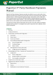
Reading is done electro-optically, as follows:
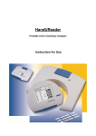
Figure 1: Principle of measurement
The LEDs (1) subsequently emit light of a defined wavelength onto the surface
of the test pad (2) from directly above the test zone. The light hitting the test
zone is reflected more or less intensely depending on the degree of color
change of the test pad (directly related to the concentration of the particular
constituent in the urine), and is picked up by the detectors, photodiodes (3)
positioned at optimum angles. The phototransistors send analogue electrical
signal to an A/D converter (4), which changes it to digital form. The
microprocessor (5) then converts this digital reading to a relative reflectance
value by referring it to a calibration standard.
Finally, the system compares the reflectance value with the defined range
limits (reflectance values that are programmed into the analyzer for each
parameter) and outputs a semi-quantitative result (6).
Each test pad is read photometrically after a lead (incubation) time of about
55–65 seconds.
10 / 85
C System description
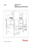
C.2
Components and Functions
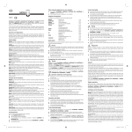
Picture 1 : Front view
Component
1. Printer cover
2. Printer cover button
3. Display
4. Test strip tray
5. Power inlet socket
6. PS2 socket
7. Serial interface
8. USB B socket
9. Ethernet socket
(PRO)
10. USB A sockets
11. On/Off switch
Picture 2: Rear view
Function
Flips up for insertion of printer paper
Push to open the printer cover
LCD touch screen for interfacing with the user
Holds the strip
Socket used to connect the analyzer to the
mains adapter
For connecting a barcode reader or a keyboard
For connecting a personal or host computer
Socket used for serial-USB
Socket used to connect the analyzer to an
Ethernet network
Multifunctional socket used to connect USB
devices
Powers the unit on. May be used to power the
unit off.
The standard power off procedure should be
started from the user interface.
Only connect the intended devices to the corresponding interface. If
you connect another device to the corresponding interface, the device or
the analyzer may be damaged e. g. because of wrong voltage. Be sure to
check all cables you are using to make sure they are operational. Verify
the proper connection.
11 / 85
C System description
C.3
Instrument and Labeling Symbols
This section describes the symbols that appear on the exterior of the
DocUReader 2 analyzer, the power supply provided with the instrument, the
packaging in which the instrument was delivered and the supplies of reagent
strips which you will use with the instrument.
Double insulated product
or transformer may also
identify class 2 equipment
(power supply only)
Identifies
that
the
instrument is listed by
Underwriters Laboratories
as
meeting
U.S.
and
Canadian requirements for
safety
Indoor use only
The CE mark identifies that
the product complies with
the applicable directives of
the European Union
This product has been
tested to the requirements
of
CAN/CSA-C22.2
No.
61010-1, second edition,
including Amendment 1, or
a later version of the same
standard incorporating the
same level of testing
requirements.
12 / 85
This
system
contains
certain toxic or hazardous
substances or elements.
The
environmental
protection use period for
this system is 10 years.
The system can be used
safely
during
its
environmental
protection
use period. The system
should
be
recycled
immediately
after
its
environmental
protection
use period has expired.
Indicates
that
this
equipment is classified as
Waste
Electrical
and
Electronic
Equipment
under the European WEEE
Directive. It must be
recycled or disposed of in
accordance with applicable
local requirements.
In vitro diagnostic medical
device
Caution, consult
accompanying documents
C System description
Manufacturer
Catalog number
Consult instructions for use
Serial number
Indicates a power on/off
button
USB port symbol
Ethernet port symbol
DC
Adaptor
Centre Positive
Do not use if package is
damaged
Keep this way up
Handle with care
Stack no more than 4
Temperature limitation
Humidity limitation
Polarity
Atmospheric pressure
limitation
Batch code
Use by date
The number of items that
the contents of the pack is
sufficient for
Do not reuse
Protect from sunlight and
heat
Keep dry
13 / 85
D Unpacking & Set Up
D Unpacking & Set Up
D.1
Unpacking
Read the DocUReader 2 Operator’s Manual carefully before
installation, so as to ensure proper operation of the analyzer from the
outset.
Follow the specified installation instructions carefully. Otherwise,
inaccurate results or damage to the analyzer may occur.
Check the carton and instrument for visible signs of damage; if seen, contact
the carrier immediately.
Carefully remove the contents of the shipping carton, remove each of the
wrappings and check for the following items:
List of delivered parts:
• DocUReader 2 analyzer
• Power supply
(AC Adapter 100V–240V, 50/60 Hz)
• Power supply cord
If the power cord is not the style
you need, Contact your service
representative
• Operator's Manual CD
• Quick Reference Guide
• Test strip tray
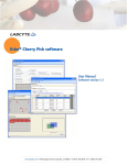
Picture 3: Contents
Do not touch the reference pad
• Roll of printer paper
• Check strip
Do not touch the check area, hold it by the handle
D.2
Setting up
Place the instrument on a solid, level surface where the temperature and
humidity are fairly constant.
Make sure the instrument is allowed to acclimatize to room temperature prior
to use.
Make sure that you
•
•
•
14 / 85
Do not place the instrument in close proximity to sources of strong
electromagnetic radiation or vibration sources
Do not place the instrument near heater devices, ovens or air
conditioners
Do not expose the instrument to strong light sources (e.g. direct
sunlight)
D Unpacking & Set Up
D.2.1
Plugging analyzer in
Only use the power supply adapter included with the unit. Connect
the analyzer to grounded power outlets only.
1. Plug the cable of the power supply
into the power inlet socket located
on the rear of the DocUReader 2
analyzer.
2. Plug the appropriate end of the
power cord into the power supply.
3. Plug the other end of the power
cord into a readily accessible AC
electrical wall outlet.
Picture 4: Analyzer plugged in
D.2.2
Inserting test strip tray
Do not touch the reference pad.
Insert the test strip tray into the analyzer by holding it by the end with the
opening (opposite the reference pad) and with the channel facing up. Push the
test strip tray into the analyzer, pushing it in until the reference pad
disappears into the housing.
Picture 5: Loading test strip tray
15 / 85
D Unpacking & Set Up
D.2.3
Loading the paper roll
Open the printer cover by pushing the printer cover button. The cover can then
be lifted back.
The printer head may be hot, do not touch it.
Place the paper roll in the compartment and pull out the first few centimeters
of paper just beyond the edge of the compartment. The thermosensitive side of
the paper (the outer surface of the paper roll) should be facing downwards.
Close the cover again by pressing until it locks audibly into position.
Picture 6: Opening the printer cover
Picture 7: Loading the printer paper
Picture 8: Analyzer loaded with paper
To remove the printed test report, tear off the paper by pulling it towards the
front across the edge.
The analyzer is set up to print the results automatically (to turn off the
automatic print function see G.2.2).
16 / 85
D Unpacking & Set Up
D.2.4
Interfacing to a computer
The instrument can send results to a computer via the serial port located on
the back of the analyzer. This requires a D-sub, 9-pin serial cable (male on
instrument side, female on PC side).
Connections:
DocUReader 2
Host(PC pinout 9-pin)
1
1
2 _____________ TxD _____________ 2
3 _____________ RxD _____________ 3
4
4
5 ____________ GND ____________ 5
6
6
7
7
8
8
9
9
Connected PC must satisfy the electrical safety requirements laid down in EN
60950.
D.2.5
Powering up
Press the On/Off button located at the rear of the instrument. The system
starts with an audible beep.
Picture 9: Powering up
17 / 85
D Unpacking & Set Up
D.2.6
Powering down
Do not remove the power cable while the instrument is operating, otherwise
the data may be corrupted or the system may be compromised.
Before turning the analyzer off, always ensure that there is no strip on the test
strip tray and that the tray is clean.
Screen 4: Powering down
The analyzer is switched off by pressing the
button on the Main or on the
Login (PRO) screen. The test strip tray will retract into the analyzer.
We recommend that the analyzer be switched off at the end of each working
day and that the mains adapter be unplugged from the AC wall socket.
If necessary, the analyzer can also be switched off by holding down the
On/Off button for at least 5 seconds. Please note that this feature should be used
in case of system freeze or LCD failure. In this case the test strip tray will not be
retracted.
D.3
Analyzer software updates
From time to time 77 Elektronika will add new
improvements to the DocUReader 2 analyzer software.
features
and
make
Updating the software is a simple procedure, but for the upgrade to work
properly, it is important to follow the instructions below precisely.
A previously prepared USB flash drive is required for the upgrade.
Either you will receive an already prepared USB flash drive from your local
distributor or you will have to upload the update files manually to a USB flash
drive if you received the software update in electronically distributed package.
Instructions for preparation of the USB flash drive can be found in the next
chapter.
1 Power on the instrument and wait until the system is ready to use.
18 / 85
D Unpacking & Set Up
2 Plug the USB flash drive into one of the USB A connectors on the back of the
device. Wait until the
disk icon appears in the status line. The icon shows
that the USB flash drive was recognized by the system.
3 Go to Settings (2)»Update screen. The analyzer recognizes that a software
update package is available and verifies the integrity of the package. If the
package is verified, the Update button will be available.
If no update source was found by the system, the button name is changed to
Refresh. Push the Refresh button to force the system to check again all update
peripherals.
4 To start the process, press the Update button. The update will be performed
automatically.
5 After the update is finished successfully, press the Restart button and
remove the USB flash drive.
Please note that the update process will not overwrite or delete the existing
database or your settings.
D.3.1
Preparation of the USB flash drive
If you received the software update in electronically distributed format, please
follow these instructions for preparation of the USB flash drive.
To copy the update package on the USB drive you will need a PC and some
basic knowledge of the operating system.
1)
2)
Create an ’update’ directory in the root of the USB drive.
Unzip and copy the content of the whole package into the ’update’
directory.
The file names will be similar to these: udr2base_x.x.x.tar.gz,
udr2base_x.x.x.tar.gz.chk, iUD2vX, iUD2vX.chk (x, X are replaced with numbers).
In case of DocUReader 2 Pro 'base' is replaced with 'pro'.
D.3.2
Available sources for software updated
The software update is possible from various sources:
•
•
•
USB flash drive,
microSD card,
code chip.
If you receive an updated description with the software update,
please follow those instructions.
The sockets for external microSD card and code chip are located under the
printer cover and are on the right-hand side of the printer when you face the
front of the instrument. The code chip socket is above the microSD card
socket.
Special instructions for updating the software on your instrument from
microSD card or code chip will be supplied with them.
19 / 85
E Use of the instrument
E
Use of the instrument
All inputs are done via the touch screen (if no external keyboard or barcode
reader is attached).
E.1
Screens
The touch screen guides you through the operation of the DocUReader 2
analyzer. The screen displays messages, instructions and options to which you
respond by touching the appropriate area on the screen.
The screen layout can be divided into three main areas:
(1) Header: Displays important system
information, like date&time, user ID (PRO),
queue and status line messages.
The color background of the status bar
changes with the state of the system. Yellow
means warning, red means error.
The active errors and warnings can be
listed by pressing the status bar area.
(2) Content navigation: Indicates the main
and subsections in which you are working. It
gives you a way to keep track of your location
within the program. The » sign serves as
hierarchy separator.
Screen 5: Layout
(3) Content area: Main operation area
The first main screen you see is the Measure screen. In the work area you can
facilitate a measurement, review the last result, handle the worklist, cycle
through the worklist items and go to the QC, Main and Data screens.
In some cases, the screen will also display instructions, messages or error
messages.
E.2
Interacting with the touch screen
How to touch the display
The screen needs to be touched gently, but firmly in the touch-sensitive area
to activate a response. The touch-screen can be operated while wearing
gloves.
Never use a hard or sharp object to operate the touch screen as they
can damage the screen.
A separate foil layer is attached to screen in order to prevent liquid leakage
into the system.
By default the sound is switched on. A successful touch event is also
confirmed with a short beep signal.
20 / 85
E Use of the instrument
Where to touch the screens
Generally the framed areas respond to touching the screen: buttons, checkbox
buttons, round radio buttons and text input fields.
Buttons
The rectangular buttons are used to trigger action and to navigate in the
menu. The boxed areas vary in size. To show clearly that a button is also used
for navigation purposes, it has an additional button indicator.
Indicator in the bottom left corner: The button closes a screen and
moves back to an upper level in the menu hierarchy.
Indicator in the top right corner: The button opens a new screen and
moves down in the menu hierarchy.
Special buttons
Apply
Drop
Inactive buttons are grayed
out.
Down
Left
Selection buttons
Up
Right
Up and down buttons are also used to scroll through
Left and right buttons are also used to cycle through values.
a
list.
Navigation buttons
Back
Drop modifications and Back
(Drop&Back)
Next
Apply modifications and Next
(Apply&Next)
Back
(Return)
Forward
(More)
Confirmation of changes
To confirm the performed changes on the User
options or a Settings screen first press the
Apply and leave the screen with the Back.
To cancel the modifications simply press the
Drop&Back before applying changes.
Changes
are
still not saved
No changes or
changes
are
saved
Drop
&Back
Apply
Back
Checkbox buttons
Check boxes are used when an option can be enabled or
21 / 85
E Use of the instrument
disabled (e.g. Autostart) or the user can select one or more options from a
set of alternatives (e.g. QC options: forced QC, L2, L3)
Round radio buttons
These buttons typically appear on screens that require a
selection from several items. The button with a filled circle is
the current selection.
To change your selection, touch an unfilled circle. The newly selected circle
(button) will now be highlighted.
Input fields
Input fields are used for alphanumeric data input. To edit the field value, press
the input area. If the input area is active, the cursor sign (|) appears in it.
Entering information directly on the instrument
When the screen prompts you to enter information, a numeric or alphabetical
keyboard appears on the screen.
Numerical input
Character input
selection
Character input
Numbers can be entered easily. To enter an alphabetical character first select
the button representing the character group, and then select the lowercase or
upper case character. To enter special characters use the special selection
.,;-:+*… or ()[] buttons to go to the selection list. To switch between the
numeric and alphabetic keyboard, use the 123 and abc buttons .
Wrong entries may be erased by pressing backspace . To move the cursor
left and right use the movement buttons . To cancel entering a character
from the actual selection list, press button . Once you have finished entering
the information, touch Apply or Apply&Next.
22 / 85
E Use of the instrument
E.2.1
Touch screen calibration
When touch screen calibration is required?
The instrument’s touch screen is properly calibrated in the factory. However it
may be necessary to recalibrate the touch screen. If you go to touch a
particular button of the screen and nothing happens, or another menu pops up,
your touch screen is not calibrated correctly.
How to calibrate the touch screen of the DocUReader 2?
While the instrument starts (during the boot sequence), a progress bar shows
the boot procedure. When the green signs appear, press the display and hold it
until the yellow screen appears to start the calibration process.
To calibrate the touch screen you have to touch the screen at the center of
each crosshair subsequently at each corner and finally the center of the screen.
Background information
Touch screen input devices are actually entirely separate devices from the
display screens that they overlay. As a result, there is no built-in relationship
between the coordinates of a spot on the display screen and the coordinates
sensed when someone touches directly over that spot. Instead, the software
for the touch screen interface must learn which spots on the touch sensor
overlay which spots on the screen. This is called touch screen calibration.
E.3
Data input: Barcode reader, keyboard
External accessories, like keyboard and barcode reader may not only speed up
the sample management process, but the accurate data entry reduces the
transcription errors as well.
Using a barcode reader: connect the barcode reader to the PS2 jack or USB
port at the rear side of the instrument. The barcode reader can be used to
enter the following information: sample ID, patient ID, QC LOT number,
registration code, strip LOT number. Power is supplied by the barcode reader
interface. The barcode reader shall support ALT mode.
Before using the barcode please do not forget to set its interface selection to
ALT mode. The following types were successfully tested with DocUReader 2:
•
•
•
•
CipherLab CL1000
DataLogic QuickScan I QD2100
Datalogic Touch 65 Pro
Intermec Scanplus 1800 SR
Using a standard PC-keyboard: Connect the keyboard to the PS/2 jack or
USB port at the rear side of the instrument.
User inputs on the keyboard may not only serve to enter data into sample
fields (i.e. sample ID, patient ID, etc.).
23 / 85
E Use of the instrument
Entering data for input fields (Sample ID, Patient ID, Operator ID, etc.)
When an input field is active enter the data directly with the keyboard, no
shortcut button is required. To delete a character, use backspace. To
cancel the input and move back to the previous screen, press Escape. To
accept the entered value and to move to the next screen press Enter.
You can also use keys to navigate between
screens or to perform actions as an alternative
to using the touch-screen.
To show the shortcuts on the screen press Ctrl,
the shortcut key will be displayed on the top left
corner of each button.
To execute the command, press the desired
character on the keyboard (you may keep the Ctrl
button pressed or release it before, the system
will work both ways).
Another option to cycle through the buttons is to
use the Tab key. When the Tab key is pressed the
'focus' cycles through the buttons forward. To
cycle backward, use Shift+Tab key together.
24 / 85
Screen 6: Keyboard shortcuts
displayed above buttons
E Use of the instrument
E.4
Flow-chart of the menu structure
Figure 2: Menu structure
25 / 85
E Use of the instrument
Figure 3: Menu structure (continued)
26 / 85
F Start-Up Wizard
F
Start-Up Wizard
The first time your DocUReader 2 analyzer is turned on, it will take you
through a quick set up procedure. This procedure will allow you to select the
basic functions of the analyzer so you can use the analyzer with your choice of
settings.
The Start-Up Wizard will allow you to select the following settings:
•
Language
•
Date and time ( K.2 Date, time)
•
System security ( K.14.2 Modifying security settings)
o
Change ‘supervisor’ operator password
(optional: depends on selected security level)
•
Testing workflow ( G.2.2 Customization of testing)
•
Printout ( K.3 Printout)
•
QC ( I.1QC Options)
o
Add operators ( K.14.5 User management)
(optional: depends on selected security level)
If you wish to skip the wizard and perform it another time, press Skip on the
second screen.
If you require further instructions regarding how to change the settings see
K Instrument Settings.
At the end of wizard press Start to finish the wizard.
You can review all settings on the 'Options » View' settings screen. All
settings, including connectivity ('Output') can be changed at 'Options »
Settings' screens.
27 / 85
G Testing
G Testing
The analyzer can be set up to be as simple or sophisticated as you prefer. You
may simply insert a dipped urinalysis strip into the analyzer and the result will
be reported. By modifying the user options the measurements can be started,
printed and transferred automatically.
Alternatively, you have the option to enter the Sample ID, Patient ID, and
color, clarity of the specimen manually (See G.2 Test features and
customization). The walkthrough for full testing is found in G.3 Full Test.
The analyzer can be operated in two different modes:
1.
In normal mode, the system automatically waits for the strip to
incubate for 1 minute before it reads the first test pad. This is the
default mode and the throughput in this mode is approximately 50
strips per hour.
2.
In fast mode, which can be selected at User Options, the test strip is
measured directly after starting the test. In this case, it is up to the
user to time the incubation period outside the analyzer (see G.2.1).
If you require more information regarding use and storage of test strips,
please refer to the strip’s instructions of use.
G.1
Quick Test
After switching on the instrument starts with the Measurement screen.
The Measurement screen can also be directly reached from the Main and
Database screens
The test strip tray has to be correctly loaded into the reader. Have the test
strip, urine sample and paper towel ready too.
Do not use damaged strip.
1 Dip the reagent strip 2 Drag the edge of the 3 Blot by touching the
into the urine sample, strip against the side of edge of the strip to the
wetting
all
pads. the sample container as paper towel to remove
Immediately remove the you remove it.
excess urine.
strip from the urine.
28 / 85
G Testing
Place the reagent strip in the 5 The instrument will automatically
channel of the table with the test detect
an
applied
strip.
The
pads facing up. Slide the strip to end measurement cycle will be started.
of the channel.
If "Autostart" feature is deactivated,
the measurement must be started
using the Start button.
4
Do not push or pull the test strip tray.
DocUReader 2 will perform a sequence of checks (reference pad, strip
detections (position of, slipped strip, dry strip, etc.) each time a test is run. See
G.2.3 Strip checking events for more information
A warning message displays if you are not using LabStrip U11 Plus,
or the strip is not positioned correctly or the strip is (partially) dry. See
0
29 / 85
G Testing
Strip checking events for more information
6 The strip position is 7 A timer will count 8 The analysis of the
checked
before down the time remaining strip pads will begin.
measurement.
for analyzing the strip.
To abort a measurement press the Back
icon on the Analyzing screen and
press Stop/Drop on the Measurement screen.
Comment can be also added during the countdown time.
After approximately 60 seconds the pad results will be displayed on the screen
and the test strip tray is automatically moved out of the analyzer.
The buttons remain inactive until the tray is fully moved out.
If Autostart is ON: The result screen will be displayed until you remove the
test strip from the tray. Once the strip is removed, the display automatically
returns to the Measurement screen.
If Autostart is OFF: The result screen will be displayed for approximately 5
seconds –while displaying a circle animation–, than the display will return to
the Measurement screen (if no error occurred during the readout). If you
touch the display while the circle animation is displayed, the system will not
automatically return back.
30 / 85
G Testing
9 Result Page 1/2
10 Result Page 2/2
Picture 10: Printed result
The pad results are displayed on the first page. Positive findings are clearly
marked with red text on the display. To view the remaining test results, touch
the Right
icon on the screen.
The printout is light-sensitive and may turn yellow when exposed to light
during storage. Test results which diverge from negative or normal values are
flagged with an asterisk before the parameter concerned. The printout can be
fully customized, see K.3 Printout for more details. For archiving purposes
the printouts should be kept in a dark place (patient file) or as a photocopy.
Functions on the result screen
•
By pressing Delete
button the result can be dropped.
•
By pressing the Printer
•
By pressing the Transfer
•
To go back to the Measurement, press the Meas. button.
button the result can be printed.
button the result can be transferred.
How to modify the result?
Results can be modified by pressing the Edit button on the second result page,
before the record is printed or sent.
All fields can be modified except date and pad results, even if the particular
field was not available during the acquisition.
Before performing the next measurement
From the test table, remove the used urinalysis strip and dispose of it
according to your standard laboratory procedures. Wipe the table insert, if
necessary.
G.2
Test features and customization
The testing process can be customized to the need of the laboratory. The
measurement feature settings define what activities related to testing process
(start) are automatically performed by the instrument. The measurement
31 / 85
G Testing
settings define the activities performed by the analyzer and the collected
information.
G.2.1
Features: Autostart, -print, -transfer and fast mode
The
measurement
features
can
Main»Options»User Options screen.
be
modified
on
the
Autostart: if enabled, measurement is automatically started (without further
user interaction) if a strip is placed on the test strip tray. By using this feature
the instrument can operate “touchless” (if all the additional data fields are
disabled). Default value: enabled.
Auto print: if enabled, the analyzer automatically prints the report of each
measurement. Default value: enabled.
Auto transfer: if enabled the analyzer automatically transfers the result to the
defined output (i.e. through the serial port to an LIS). Default value: disabled.
NOTE: These features can be modified by any operator and stored separately for
each operator (PRO)
Fast mode (serial reading): if enabled, the test strip is measured directly after
Measure is pressed on the Measurement screen (note: in fast mode the
large start button is renamed to Measure and the background is changed to
orange).
In this case, it is up to the user to time the incubation period outside the
analyzer. When working in Fast Mode, ensure that you have a foolproof system
for matching sequence numbers to samples.
The status of fast mode cannot be saved. After logout or system restart the
analyzer always starts in Normal mode.
When performing serial measurements in Fast Mode, allow the strips
to react for approximately 60 seconds before inserting them in the
analyzer and pressing MEASURE. False-low or false-negative results may
be obtained for some parameters if the reaction time is too short.
Likewise, false-high results may be obtained for some parameters if the
incubation time outside the analyzer is too long.
The option to enable Fast mode only appears on the User options screen, if this
option is enabled on the Settings»Measurement screen.
32 / 85
G Testing
G.2.2
Customization of testing
On the Settings»Measurement screen you can
customize which fields are enabled during
acquisition, to disable fast mode at the system
level or to allow analysis of (partially) dry strips
and modify the settings. You can set the display
units here as well.
By default all extra fields are disabled and the
display unit is set to conv-arbitr.
Screen 7: Settings » Measurement
Sample ID: The system by default assigns each reading with a consecutive
sequence number having a maximum of 7 digits. If the sample ID is enabled,
you have the option to replace the automatic ID and manually set the sample
ID during the test.
Patient ID: If enabled, you can set the patient ID during the test.
Color: If enabled, you can set the visually observed color of the sample during
the test.
Clarity: If enabled, you can set the visually observed clarity of the sample
during the test.
Fast mode enabled: If enabled, the Fast mode button is operational, so fast
mode can be enabled in User Options. If disabled, the analyzer is not allowed
to operate in fast mode.
Dry strip only warning: If enabled, the result of a (partially) dry strip with
pad values is saved in the database with a warning comment. If disabled,
(partially) dry strip results are only saved with an error code.
Display units: changes the display units on system level. Selectable options:
conv-arbitr, SI-arbitr, conv, SI, arbitr. Use the left and right arrows to change
the value.
33 / 85
G Testing
G.2.3
Strip checking events
Errors in sample handling and testing procedure may lead to false results. In
order to further improve the diagnostic decision making process advanced strip
recognition features were introduced in DocUReader 2.
The outcome of these features is categorized into three groups:
R1. Measurement is not started
R2. Result is saved with a warning flag
R3. Result is saved with an error code
The analyzer automatically recognizes the following events during testing:
Feature
Outcome
When
slipped strip
R3
3 times
(partially) dry strip
R2
R3
after testing
upside-down strip
R3
before incubation period
background light too strong
R2
R3
during measurement
If the result is saved with a flag, the pad values are listed and the code and the
description of the flag is inserted into a new comment field of the result. To
search for results with a warning flag, use the "with comment" extra filter in
the database (see H.3 Filtering: How to find specific results). Please note
that this filter will also list results with comments inserted by the user.
If the result is saved with an error, only the error code is visible. To search for
results with an error code, use the "false meas." extra filter in the database.
Slipped strip
The front of the test strip has to be at the leading edge of the test strip tray.
Systems checks for misposition:
1.
2.
3.
Before the incubation time: warning window is displayed with two
choices: 1. drop testing and restart with new strip; 2. reposition strip
and repeat measurement. Choice is available during the incubation
time.
Before the measurement: warning window is displayed with two
choices, but repeating is limited for 10 seconds. In case of successful
repositioning the result will be flagged as ’Overincubate’ (R2). After 10
seconds only 'cancel testing' option is available.
After the measurement (R3): result is stored with an error code
(’Measurement error: strip position error’).
Partially dry strip
The evaluation takes place after the measurement based on the reflectance
data of the last pad. Based on the configuration settings (see G.2.2
Customization of testing) the result is saved either with a flag (R2) or an error
code (R3).
34 / 85
G Testing
G.3
Full Test
The description of the required preparations and the testing process can be
found at G.1 Quick Test.
This section only provides additional information on the data input process
presuming that all additional fields (sample ID, patient ID, color and clarity)
are enabled.
The data input is started after strip position check. The first screen appears
when the test strip tray is moved back to the home position.
The sequence of the data input is Sample ID Patient ID Color Clarity.
If a field is disabled at Settings»Measurement, the input screen won’t
appear for it.
Sample ID: unique sample ID is
assigned by default. To change it,
use the onscreen keyboard, the
attached keyboard or the barcode
reader. Maximum 14 characters.
Sample ID must not be empty.
Sample ID: Automatic ID was
changed, you can either cancel
the change (press Drop&Back) or
apply it and proceed to the next
screen (press Apply&Next)
Reading a sample ID or patient ID with barcode will automatically take you to
the next screen.
If you require further instruction regarding barcode reader or keyboard usage
see E.3 Data input: Barcode reader.
35 / 85
G Testing
Patient ID: Use the onscreen
keyboard, the attached keyboard or
the barcode reader to enter the
patient ID. The Patient ID field can
be left empty. In this case press
Next button at the bottom right
corner to move to next screen.
Maximum 32 characters.
Patient ID: Touch Apply&Next,
when you have finished entering the
patient ID and proceed to the next
screen. To select a new character,
Color:
To
select
the
visually
determined color of the urine sample
press the appropriate button. This
will also take you to the next screen.
Clarity: To select the visually
determined clarity of the urine
sample press the appropriate button.
This will also take you to the next
screen.
press . To abort and go back to the
Sample
ID
screen,
press
Drop&Back1.
You can select only one color and clarity type for a urine sample
In PRO version you may customize the predefined color and clarity selection
lists.
1
Drop&Back icon is not show on the sample screen because the character
input is active
36 / 85
G Testing
After all data have been entered the next screen displayed will either be:
Analyzing …
— if the strip is still being analyzed
Result
— if analyzing the strip has been completed
It is not required to input all data during the
incubation time, the system will analyze the strip
in the background and move out the test strip
tray.
Once you have finished the data input, the Result
screen will appear.
If Autostart is ON:
The result screen will be displayed until you
remove the test strip from the tray. Once the
strip is removed, the display automatically
returns to the Measurement screen.
If Autostart is OFF:
The result screen will be displayed for
approximately 5 seconds –while displaying a
circle animation– then the display will return to
the Measurement screen (if no error occurred
during the readout). If you touch the display
while the circle animation is displayed, the
system will not automatically return back.
Picture 11: Printed report of a Full
Test
G.4
Latest result
If a measurement was performed since the analyzer was switched on, the
latest result can be easily reviewed from the Measurement screen with the
Latest button.
Here you not only have the possibility to edit the fields if necessary, but even
to revoke the result.
G.5
Worklist management
The worklist is a predefined sequence of samples and contains the sample IDs
and patient IDs in the sequence of planned evaluation.
The worklist can be generated:
•
•
manually through the touchscreen, or a connected external keyboard
or barcode reader,
or automatically by downloading the worklist items from the LIS.
The sample ID is a maximum 15 character long numeric string.
The patient ID is a maximum 33 character long string containing either
numeric, alphabetic or special characters.
37 / 85
G Testing
Push the Worklist button on the Measurement screen to go to the worklist
management.
In the Worklist menu you can:
1)
2)
3)
4)
5)
6)
Manually add, modify, delete the worklist items
Download the worklist from the LIS
Modify the sequence of the items
Search for a sample ID in the worklist
Print the worklist
Delete the whole worklist
Legend
1. Worklist items
2. Delete active item
3. Delete all items
2
3
5
4
4. Download worklist from LIS
5. Search for sample ID
6
1
6. Move up by one record in the list
7
7. Modify item
8. Move down by one record in the list
8
9. Add new item
10. Action: select actual item
11. Print worklist
12
11
9
10
Screen 8: Worklist
12. Return to Measurement menu
If the worklist is empty, only the
and
buttons are active. The
button is active, if the worklist contains at least 2 items.
Use the
Add item button to add a new entry to the list. Set the sample
and patient ID as described in the testing procedure. By using external
keyboard or barcode reader the editing process can be speeded up
considerably. The new item will be added to the end of the list. Use the
Modify button to modify an already existing record.
To change the position of the active item in the list, press the
Move
button. The button background is changed to orange
and the item can be
moved up and down in the list by using the arrows on the right side. To finish
movement, press the Move button again, so it becomes inactive.
The
Delete button removes the actual item without confirmation, while
the
Delete all button deletes the whole worklist. The deletion of all items
requires user confirmation.
38 / 85
G Testing
G.5.1
Worklist window in the Measurement menu
When you return the Measurement screen with the
worklist item will be active in the list window.
Back button, the first
If you need to manually change the order in the Measurement screen, use the
left and right buttons to cycle through the worklist.
If you also have to measure a new sample immediately, which is not in the list,
use the left or right arrow to cycle to the beginning or end of the list, so an
automatically generated sample ID will appear in the window. In this case the
(generated) text will appear under the sample ID.
39 / 85
H Recall Results
H Recall Results
The DocUReader 2 has memory for 1000 (PRO 3000) measurements. Every
result is automatically saved after the analysis in an indexed database. The
database enables you to search, view, print and transfer patient test results.
By default the analyzer warns the user to free up memory (erase data) 30
records before the limit. The analyzer can also be set up to use circular memory.
For more information on database settings see K.7 Database management.
You can access the database either
a.) from the Measurement screen by pressing Data,
b.) from the Main screen by pressing Database.
H.1
List view
The Database screen shows the results in chronological order. The most recent
test result is displayed at the bottom of the screen. Use the up and down arrow
keys to scroll through the list of tests. To move the position in the list by 100
records use the
buttons.
Legend
1. Results list
2. Actions with selected records
3. Switch: Select records by movement
2
3
4
5
4. Filter
5. Move up by 100 records in the list
6
1
6. Move up by 1 record in the list
7
7. View item
8. Move down by 1 record in the list
8
9. Move down by 100 records in the list
10. Action: select actual record
11. Go to Main menu
12
11
10
9
Screen 9: Database - List view
12. Go to Measurement menu
Color coding of the results in the list:
Black:
Negative result
Red:
Positive result
Ochre:
Failed result
If you enter from the Measurement screen, an automatic predefined filtering
is applied and only the results measured on that day are listed. This is marked
with the button. If you enter from the main menu, no filtering is automatically
executed.
40 / 85
H Recall Results
To view details of a patient result, touch the View button. The first page of the
patient’s result will be displayed on the screen.
H.2
Result view
Screen 10: Result 1/2
Screen 11: Result 2/2
The pad results are listed on the first page. You can use the up and down
navigation buttons to move between the results. Press Return to go back to
the list view. To view the second page of the result, press the More button.
On the second page the actions buttons are displayed for the record: Edit,
Print, Send for output.
The Edit button is only available, if the result has not been printed or
transferred yet.
H.3
Filtering: How to find specific results
To narrow down the list of results DocUReader 2 features a sophisticated
filtering engine. The following parameters can be used to set filtering criteria:
•
Date&Time
•
Sample ID
•
Patient ID
•
Status:
•
o
not printed,
o
not transferred
Values:
o
negative,
o
positive,
o
sediment
recommendation,
o
false,
Screen 12 and 13: Database » Filter
41 / 85
H Recall Results
o
with comment,
o
self measured
To activate a filter, press the desired button.
Active filters are labeled with orange background.
On the first page of the Filter screen, the active
filters from the second page are listed above the
navigation buttons.
To switch off filtering press the Filter OFF button.
To return to the list of results, press Return.
Screen 14: Active filters
Selecting the Date&Time
To select the filtering period, you can define the start and end Date&Time
separately on the Filter»Start time and Filter»End time screens.
When entering, the Day field is active. To change the value of the active field
use + and – buttons. To modify which field is active use up and down arrows.
Today button will set the beginning/end of the current day.
Switch on button will set the exact time when the analyzer was switched on.
Press Cancel to discard the changes and return to the filtering overview screen
preserving the previous filtering value.
Press Apply to apply the changes and return to the filtering overview screen
Press Clear to clear the start/end filter and return to the filtering overview
screen.
H.4
Modifying the active selection of results
If a record is selected:
•
in list view its background is blue,
•
in result view the background of Sample
ID’s row is blue.
The count of the selected results is displayed in
parenthesis at the content navigation bar
(breadcrumb) in the list and selection view.
Single selection
Use the
42 / 85
button to select/deselect a single record in the list view.
H Recall Results
Multiple selection
Press the
button to activate the 'select with movement' feature. If this
button is activated (its background is changed to orange
) the state of the
records will be modified (will be selected/deselected) by moving up and down
in the list view according to the state of the selection button.
Select all
To select all records press the Select all button on the Database»Selected
screen.
Invert selection
To invert the actual selection, press the Invert selection button on the
Database»Selected screen.
Remove selection
To remove all selections, press the Remove selection button on the
Database»Selected screen.
H.5
Action with selected items
If no record is selected, the action buttons are grayed out.
Delete
To delete the selected records, press the Delete button on the
Database»Selected screen. In order to prevent accidental deletion, a
confirmation dialog is presented on the screen.
Print
To print the selected records,
Database»Selected screen.
press
the
Print
button
on
the
Send for output
To send the selected records for output, press the Output button on the
Database»Selected screen.
43 / 85
I
I
Quality Control Testing
Quality Control Testing
The performance of the system (analyzer and reagent test strips) should be
monitored regularly to ensure reliable results are obtained. To determine the
frequency of quality control, consult your facility’s quality control policy.
The following possibilities are offered to perform QC tests:
Type
Controls
Check strip
Urine Control
2 or 3 levels
Available
Analyzer
Reagent test strips
Analyzer
PRO only
Several commercial controls are available. Controls may vary in number of
levels or components, necessity for reconstitution or ready to use, type and
volume of container. 77 Elektronika Kft. supports the use of Quantimetrix
Corporation Dipstick Controls as these controls provide the necessary color
development with LabStrip U11 Plus strip. Other manufacturers’ controls may
provide abnormal results due to non-specific colorations of the test pads.
After the occurrence of an accidental event (drops, spills, splashes),
even if visible damage is not seen, verify the performance of the reader
with the check strip.
The supplied check strip can be used only as a mechanism to confirm the
functionality of the analyzer. This is the only QC functionality offered for the
base DocUReader 2.
The use of urine controls is highly recommended particularly in the following
situations:
a)
b)
c)
d)
monthly on each open bottle,
if a new bottle of test strips is opened,
if test results are in doubt,
if new operators are trained on the system.
The urine control solutions are analyzed using a regular urine test strip in an
identical manner to a patient sample.
The QC procedure can be divided into 3 phases:
1.
Configuring the system: setting urine control level, forced QC, QC
lockout.
2.
Setting the urine control LOT number and the acceptance limits.
3.
Performing QC testing at defined intervals.
In order to perform the necessary steps:
1.
To configure the system QC settings select
Options»Settings»QC Options. I.1 QC Options
The urine control LOT number and acceptance limits can be set at the
same place. I.1.1 Editing QC
2.
44 / 85
The QC measurement screen can be reached by the QC button from
the Measurement screen or by the QC Meas button from the Main
screen. I.2 QC Testing
I
3.
I.1
Quality Control Testing
All QC measurements are stored in a separate database, to reach
them press the QC results button on the QC measurement screen.
I.3 Recall QC Results
QC Options
At the Options»Settings»QC Options screen
the analyzer Quality Control settings can be
configured:
•
•
•
•
•
enable/disable QC lockout,
set the QC lockout interval in days,
type of QC lockout (warning or forced),
define the type of control solution (2 or 3
levels),
edit the QC solutions LOT data.
The lockout mode offers the opportunity to
ensure a QC-check latest every determined
interval using control solutions.
If the lockout mode is activated, the instrument
will be released for measurements for the
determined timeframe once a successful QC check
has been performed.
Screen 15: QC Options
To enable the QC lockout and set the interval:
•
•
use the right and left arrows, or
press the grey input area, use the numeric input and apply.
If you apply changes to the QC lockout period, a popup window appears with
the modified lockout time.
The lockout mode can be
•
warning
If the limit is passed, the status bar
background is changed to orange and a
warning message is displayed.
•
forced
If the time limit is passed, the status bar
background is changed to red and an
error message is displayed. In this case
the measurement feature will be blocked
until a new successful QC check has been
performed.
Screen 16: Forced L2 QC
45 / 85
I
Quality Control Testing
The QC check can be set for
1)
2)
two level urine control solutions (L2: negative/normal and
positive/abnormal),
three level urine control solutions (L3: negative/normal, low and high
positive/abnormal).
If strong user security is applied ( K.14.2 Modifying security settings) the
normal users are not able to modify the QC settings, so the QC policy determined
by the system administrator will be forced. However if the analyzer is locked out
and you need to make a measurement immediately without performing the QC
check first, the lockout mode can be switched off only by an Administrator.
I.1.1
Editing QC LOT information
The QC evaluation relies on the manually inputted data. Verify the
values prior usage.
Press the Edit QC LOT button on the QC options
screen to set the QC Urine Control solution LOT
numbers and their acceptance limits.
1) On the next screen select the control level
(L1, L2, L3) and press the
Next button.
2) On the next screen set the LOT code (you
may also include the expiry date) and press
the
Next button. If a LOT code is
already stored for the actual level, its value
will appear in the input field.
3) On the last screen set the acceptance limits
for the selected level of the LOT.
Please note that the software does not
validate against the expiry date of the QC LOT
Screen 17: Select QC Level
Modifying the limits
The selected level appears in the top left corner of
the table. The LOT code is shown in the
navigation bar. The columns of the table are:
parameter, lower limit, higher limit, unit.
The selected cell is marked with black borders
(see pH higher limit on Screen 18: QC Limits).
Use the arrows to navigate and change the actual
selection. The value of the lower and higher limit
of the selected item can be increased or
decreased with the
and
buttons.
When you have finished, press the
OK button
to store the values. The analyzer returns to the
QC options screen.
Repeat the previous steps for all levels.
46 / 85
Screen 18: QC Limits
I
I.2
Quality Control Testing
QC Testing
To perform a quality control measurement go to the Measurement»QC
screen. The color coding of the QC measurement buttons is the following:
A.
QC lockout is disabled:
o grey: not measured,
o green: valid measurement was performed while in the QC Meas
menu
o red: invalid measurement was performed while in the QC Meas
menu
B.
QC lockout is enabled:
o grey: not measured,
o green: valid measurement was performed within the time limit
o red: invalid measurement was performed within the time limit
You can start either with a negative or with a positive control. Apply the control
to the strip according to the instructions of the control solutions and the
LabStrip U11 Plus test strips.
We recommend using the Dipper, the Dropper or the Dip&Spin control
solution kits from Quantimetrix Inc. to carry out the QC-Check. Controls of other
manufacturers may provide abnormal results due to non-specific colorations of the
test pads.
Place the strip on the tray and press
•
•
•
"… Solution 1" for negative control,
"… Solution 2" for positive control,
or "… Solution 3" in case of Level 3 for high positive control,
depending on the control you are currently testing.
If the QC LOT and its limits were already set at the QC settings, the analyzer
offers the QC LOT code. Press the Next button.
The QC LOT code can be modified here as well. If a new LOT code is given, its
acceptance limits have to be set as well, so the limits table will appear on the next
screen.
After measurement, the QC result is displayed with the result of the evaluation.
•
•
If the QC measurement is successful, PASSED text is displayed after
the QC result Id. Returning back to the main QC screen, the measured
solution’s button background is changed to green.
If the QC measurement has failed, red FAILED text is displayed after
the QC result Id. Returning back to the main QC screen, the measured
solution’s button background is changed to red.
Repeat the same procedure with the other solution(s).
After all required solution levels have been successfully measured (all
"…Solution…" buttons are green), the analyzer is released until the lockout
time is reached and a popup window appears with the modified lockout time.
The remaining lockout time together with the date is displayed in the
information windows of the Main screen.
47 / 85
I
Quality Control Testing
The maximum displayed negative value is -90. It may mean that more than
90 days has passed since the limit or a successful QC was never performed.
I.3
Recall QC Results
All QC measurements are stored in the QC memory, which is separated from
the memory for the patients’ measurements. The DocUReader 2 has memory
for 500 (PRO 1000) QC measurements.
See H. Recall Results for more information on how to recall and view results
from a database.
Only the additional information specific to QC the database is described in this
chapter.
In the list view the good results have black text, while any failed results have
red text.
In the QC result screen PASSED text is displayed after the good QC result Id,
while red FAILED text is displayed after the failed QC result Id. For failed QC
solution results the out of range pad results are also marked in red.
The QC solution results have a second page, where the set limits are listed.
48 / 85
J Options menu
J
Options menu
The Options
information:
•
•
screen
displays
the
following
strip type and LOT code information,
output settings.
The following functions can also be reached from
this screen:
•
•
•
•
•
Registration Code,
Strip LOT,
View Settings,
User Options (auto features; fast mode;
sound; LCD brightness),
Instrument Settings.
Screen 19: Options
J.1
Registration Code
The encoded registration code contains strip related information allowing the
DocUReader 2 analyzer to control the evaluation precisely:
•
•
•
expiry date of LOT,
calibration information for the particular LOT (possible sensitivity
adjustment for each pad determined by the manufacturer),
maximum counts of measurements allowed with the given calibration.
Calibration is required to obtain proper results.
Please note, that a vial of test strips and calibration are co-related.
The Registration Code screen shows the expiry date and the remaining
counts.
When opening a new shipment or a vial of strip, the registration/calibration
card can be found in the package. The unique registration code is affixed to the
registration card and it is valid for 1/10/20 vials.
To enter the numeric code on the card press New Registration Code button.
Either type in the 15 digit number or input the information using a barcode
reader. After successful registration the number of available tests is set to the
value of the registration code.
Please note, that the remaining quantity from the previous code will be
disabled! If later you want to re-use a previous code, you only have to enter it
again and the remaining quantity will be restored again.
J.2
Strip LOT
Push the Strip LOT button on the Options screen to set the LOT information of
the strip. It is also possible to set the expiry date after the LOT code.
49 / 85
J Options menu
The following special characters are allowed for input together with numbers:
hyphen '-', dot '.', forward slash '/', space '_' and round brackets '(' ')'.
This information is stored with every measurement, until it is changed
manually.
Please note that the LOT code and expiry date values are semantically not
checked by the software. Also as the registration code does not contain the strip
LOT code, the software cannot check if the LOT code is correct. Please double
check the LOT code in order to avoid typos.
J.3
View Settings
The View settings screen shows all settings including user options as well.
Use the down and up buttons to scroll through the settings. The analyzer
settings can be printed out using the
J.4
button.
User Options
Most of the settings on the User options screen are related to the testing
procedure except Sound and LCD brightness.
Autostart: if enabled, measurement is automatically started (without further
user interaction) if a strip is placed on the test strip tray. By using this feature
the instrument can operate “touchless” (if all the additional data fields are
disabled). Default value: enabled.
Auto print: if enabled the analyzer automatically prints the report of each
measurement. Default value: enabled.
Auto transfer: if enabled the analyzer automatically transfers the result to the
defined output (i.e. through the serial port to an LIS). Default value: disabled.
NOTE: These features can be modified by any operator and stored separately for
each operator (PRO)
Fast mode (serial reading): if enabled, the test strip is measured directly after
Measure is pressed on the Measurement screen (note: in fast mode the
large start button is renamed to Measure and the background is changed to
orange).
In this case, it is up to the user to time the incubation period outside the
analyzer. When working in Fast Mode, ensure that you have a foolproof system
for matching sequence numbers to samples.
The status of fast mode cannot be saved. After logout or system restart the
analyzer always starts in Normal mode.
When performing serial measurements in Fast Mode, allow the strips
to react for approximately 60 seconds before inserting them in the
analyzer and pressing MEASURE. False-low or false-negative results may
be obtained for some parameters if the reaction time is too short.
Likewise, false-high results may be obtained for some parameters if the
incubation time outside the analyzer is too long.
The option to enable Fast mode only appears on the User options screen, if this
option is enabled on the Settings»Measurement screen.
50 / 85
J Options menu
Sound: if enabled the analyzer confirms the touching actions with a short beep
sound
LCD brightness: Use the left and right buttons to change the brightness of
the LCD display or click on the input field to set the LCD brightness value from
a numeric keyboard.
Change passw.: (PRO only) the active operator may change the password by
pressing the Change passw. button. First the system asks for the current
password, than the new password has to be repeated twice. The system
confirms the successful change.
The change passw. button appears only if an operator with a password is
logged in to the system. In case of 'autologin' operator this button does not
appear.
The minimum password length is 3 characters.
51 / 85
K Instrument Settings
K Instrument Settings
Your DocUReader 2 analyzer allows you to change settings to suit your
workplace requirements. Instrument settings can be reached from
Main»Options»Settings.
The list of available settings may vary according to authenticated user level.
Screen 20: Settings 1/2
Screen 21: Settings 2/2
To navigate between settings pages use the back and forward arrows.
Confirmation of changes
To confirm the performed changes on the User options or a Settings screen
first press Apply and leave the screen with Back.
No changes or changes are saved
Changes are still not saved
To cancel the modifications simply press Drop&Back before applying
changes.
Restoring default values
On each settings screen there is a button (named Restore Default or DEF.),
which can be used to restore the default value(s) for that screen.
To restore ALL settings on the system level go to Manage Settings.
At system level the settings cannot be restored while printing or transfer is in
progress.
For PRO only: The settings can be restored based on the settings of supervisor
user, if the 'Default by "supervisor" settings' switch is active on Manage
settings page.
52 / 85
K Instrument Settings
K.1
Language
To change the operating language select the desired language from the list and
apply change.
If the translation is partially done in the selected language, the non-transleted
texts appear on English.
K.2
Date, time
The date and time are displayed on the header
and are recorded with the test results.
To Modify which field is active use the up and
down arrows.
To change the value of the active field use the +
and – buttons.
Available date formats:
YYYY-MM-DD (default, ISO 8601
standard)
MM-DD-YYYY (US format)
DD-MM-YYYY (EU format)
Available delimiters: '-', '/', '.'
Screen 22: Settings » Date/Time
K.3
Printout
Printout Header: custom string
Patient ID:
If ON, ~ appears on the printout
Operator ID:
If ON, ~ appears on the printout
Device S/N:
If ON, ~ appears on the printout
Sediment rec: If ON, sediment recommendation
information appear on the printout
Strip LOT:
If ON, ~ appears on the printout
Empty always: Always print the field, even if it is
empty
Units selection: changes the display units of the
printouts. Selectable options: conv-arbitr, SIarbitr, conv, SI, arbitr. Use the left and right
arrows to change the value.
Screen 23: Settings » Printout
53 / 85
K Instrument Settings
K.4
Output (Connectivity: Transfer/Export)
At the Output settings you can define how the DocUReader 2 will connect to
other systems or storage devices.
The analyzer supports many possibilities for
transferring the results through an interface
(serial, USB or file):
1.
bidirectional protocol based on NCCLS
LIS2-A2 standard protocol,
2.
unidirectional protocol, when the data
are sent out in a one-way data flow,
either in the format of
a.
comma-separated values, or
b.
UTF8 text.
Screen 24: Settings » Output
The Output type input field is used to define the communication port (the
available selection is based on the output protocol) on the Output screens.
Press the Left and Right arrow to scroll through the list.
Serial
(RS232)
TCP/IP
Ethernet
Bidir: LIS2 (ASTM+)
⊕
⊕
Unidir: CSV
⊕
⊕
⊕
Unidir: UTF8 text
⊕
⊕
⊕
File
USB B
⊕
For serial port the selectable baud rates are 2400, 4800, 9600, 19200, 38400,
57600, 115200. The value defines the speed of the serial communication. The
serial interface specification: 1 stop bit, no parity.
For file output the transferred data will be saved directly to files, if
"Output: file" is selected. The default file name is udr2(%Y%m%d-%H%M%S).
In the file name the signs are replaced with values: %Y: year; %m: month;
%d: day; %H: hour; %M: minute; %S: second. The file extension depends on
the selected output protocol.
Make sure to configure properly the communication ports, otherwise data
transfer will not work.
54 / 85
K Instrument Settings
K.4.1
Bidirectional protocol (LIS2-A2)
The two-way digital transmission protocol of
DocUReader
2
analyzer
regarding
remote
requests and results between DocUReader 2 and
information systems is based on the NCCLS
LIS2-A22 approved standard.
It enables DocUReader 2 and any standard LIS
system,
to
establish
a
logical
link
for
communicating text to send results and requests
in a standardized and interpretable form.
You can set a custom header and at the Output
type input field you can define
1.
the output type: serial, USB B, TCP/IP
(Ethernet)
2.
the
speed
of
serial
(only for serial port).
communication
Screen 25: Output » LIS2
If TCP/IP (Ethernet) is selected, please set the server’s IP address and port
separated with ':' symbol.
K.4.2
Comma-separated value output
Separator: tabulator, semicolon, comma
2
NCCLS LIS2-A2: Specification for Transferring Information Between Clinical
Laboratory Instruments and Information Systems; Approved Standard—
Second Edition (Volume 24 Number 33)
55 / 85
K Instrument Settings
K.4.3
K.5
UTF8 unidir text (STUB)
Measurement
The detailed description of the Measurement screen can be found in
G.2.2 Customization of testing.
K.6
Strip options
The main strip options screen shows the available
strip types. To modify the strip settings select the
appropriate strip type and press the order,
sensitivity button.
The next screen Settings»Strip»Pads lists the
pads of the strip.
The active pad is marked with a rectangular black
frame.
To change the active pad, use the up and down
arrows.
To change the sensitivity of the pad press
or
to increase or decrease the sensitivity of the
pad.
Screen 26: Settings » Strip » Pads
The sensitivity can be set between -2 and +2 from the user interface.
PRO only: To set sediment recommendation press the SED button. If the pad
is labeled with SED, all results containing positive value of the selected pad will
receive a "sediment examination is recommended" flag in the database. The
information may be also presented in the printout. The flag value is stored in
the database, so the database may be filtered for this option as well (See H.3
Filtering: How to find specific results).
56 / 85
K Instrument Settings
To modify the displayed pad order:
1 Select the pad.
2 Press the Move
button. It will be active and
its background will be changed to orange.
3 Use the up and down arrows to move the
position of the selected pad. If it is at the desired
position, press the Move button to deactivate the
movement and release it.
If you want to exclude a specific pad from the
results view, move the pad below the —Invisible—
line. The pads below this line won’t be listed in
the results.
Screen 27: Invisible pads
Please note that the invisible pads will be always analyzed as well and the
results are also stored for these in the database. So if you change the visibility
settings later, information will therefore be available for these too.
K.7
Database management
At the Database management screen you can define how the DocUReader 2
manages the storage of the records.
You can specify the following:
•
•
•
•
K.8
The automatic Sample ID counter can be
reseted by pressing the Counter reset
button. The execution requires confirmation.
Circular memory on or off. Circular memory
on will continuously record, writing over old
data when memory is full. Circular memory
off will stop recording when memory is full.
Warning at…: If it is on, you receive a
warning before old data is overwritten.
Prewarning: define the amount of records
when you receive warning before the
memory is full. Adding new records is still
possible but you are advised to free up
Screen 28: Settings » Database
database memory by erasing data.
QC options (PRO only)
The detailed description of the QC options screen can be found in I.1 QC
Options.
57 / 85
K Instrument Settings
K.9
Power management
At the Power Management screen you can enable
and set the value in minutes for the following
options:
•
•
•
LCD off time (starts screensaver)
Logout time (logs out the active user)
Power off time (switches off the
analyzer)
The analyzer will perform these activities if it has
been inactive for the given time.
Use the left, right arrows to change the values:
•
LCD off time:
Disabled, 5, 10, 15, …, 60
•
Logout time:
Disabled, 10, 20, 30, …, 120
•
Power off time:
Disabled, 20, 40, 60, …, 180
Screen 29: Power Management
screen
The screensaver mode and the automatic power-off feature helps to reduce the
unnecessary power usage, thus reducing the economic footprint of the
analyzer.
The automatic logout feature however gives an additional layer of security
(available for Pro units only).
K.10 Log export
To export the log files, analyzer settings and version information for diagnostic
purposes:
1)
2)
3)
4)
Plug the USB flash drive into one of the USB A connectors on the back
of the device. Wait until the
disk icon appears in the status line.
The icon shows that the USB flash drive was recognized by the
system.
Push the Log Export button in the Settings (2) screen.
An information window appears (Log export is in progress. Please
wait.). When the information disappears, when the log export is
finished.
Remove the USB flash drive.
K.11 Editing color and clarity list (PRO only)
The DocUReader 2 Pro units allow the possibility to customize the urine color
and clarity list values according to standard lists determined by your facility’s
policy.
The color list can be edited at the Settings»Color list screen, while the clarity
list can be edited at the Settings»Clarity list screen.
To modify a value:
58 / 85
K Instrument Settings
1)
2)
press the item’s button (e.g. straw-yellow or clear),
edit the text,
3)
when you set the new name, press the
you back to the list.
OK button, which takes
The modified items will be marked with an orange background.
To accept the changes, press the
Apply button.
To restore the original list, press the Restore Default button.
K.12 Ethernet interface configuration (PRO only)
To connect the DocUReader 2 Pro analyzer to the
network via Ethernet interface through TCP/IP,
you have to configure the Ethernet interface.
The values should be provided by your
facility’s IT system administrator.
The configuration can be performed:
•
•
automatically (DHCP),
manually.
For automatic configuration select the auto
(DHCP) checkbox.
By using DHCP, TCP/IP configuration is done
dynamically and automatically when the analyzer
is started. Dynamic configuration requires a Screen 30: Eth. interface config.
properly configured DHCP server on your network.
screen
For manual configuration uncheck the auto (DHCP) checkbox and manually
assign
•
•
•
the IP address / subnet mask
(i.e. 192.168.1.5/24 or 192.168.1.5/255.255.255.0),
the gateway,
the DNS server.
To confirm the changes, press the
Apply button after modification.
K.13 Update
The detailed description of the
D.3 Analyzer software updates.
update
procedure
can
be
found
in
59 / 85
K Instrument Settings
K.14 Operators (PRO only)
The operators screen is used to manage the system security settings and to
manage the active operators.
Legend
1. List of operators
2. Delete active operator
3. System security settings
(accessible for Supervisor group members)
4. Move up by one record in the list
2
3
1
4
5. Modify operator rights
5
6. Move down by one record in the list
7. Add new operator
6
8. Activate/deactivate movement3
9. Print operators list
10. Go to Settings menu
10
9
8
7
Screen 31: Operators
By definition the user means someone who is operating the analyzer. By
definition operator means a user identified by the analyzer, with a login name.
Usually each user is identified by an operator (login name and password).
Each operator’s access level can be defined separately. All operators are stored
in a database.
To add a new operator, press the Add new button.
Selected operator: Displayed information
In the list of operators the selected operator is marked with black borders and
the operator’s user group is also displayed. Operators belonging to the
Administrator or higher group are marked with red text.
The user group of the selected operator is also displayed, followed with further
information in parenthesis. The meaning of the abbreviations is:
S: display self result only
L: may login without password (password is not mandatory for this
operator)
D: login name may be displayed on the login screen
To modify the user rights of the selected operator press the Edit button.
Listing operators on the login screen
If enabled, a maximum of four operators can be listed on login screen. The
operators who can be displayed on the login screen are marked with a blue
background. Use the Move
button to grab the selected operator and use
the up and down buttons to modify the order
3
Move button is used only for ordering the operator list on the login screen
60 / 85
K Instrument Settings
K.14.1 Concept: Operator levels
Each consecutive level inherits the rights of the previous level.
User groups
Rights
User
This is the standard user group. Members of this group can perform
routine actions such as
•
•
•
•
•
Admin
worklist management,
perform test,
run control,
report results (printing, exporting),
modify user options.
Members of the secondary user group can perform all actions of the
primary user group. Additionally they can
• configure the system (modify settings),
• manage users,
• install software updates.
Supervisor
Members of the third user group can perform all actions of the
second user group. Additionally they can
• modify the system security settings.
Certain tasks and user controls can be reached and are visible only based on
user rights.
K.14.2 Modifying security settings
The main security settings of the analyzer can be modified on the
»Operators»Security screen. This screen is only accessible for the
Supervisor group.
The DocUReader 2 offers 5 different pre-configured security levels, although it
offers an expert mode to fulfill special security requirements and system
usage.
1. Open system
Automatic login without identification and password, free modification of
settings. No security applied: Anyone can perform tests and modify the
settings using the 'autologin' operator.
2. Anonymous usage
Automatic login without identification and password for measurement; system
settings are protected. Users can add themselves as 'user' level operators.
3. Self-add
Users can add themselves as 'user' level operators at login.
4. Self-add with password
Login with operator password for measurement; system settings are protected.
Users can add themselves as 'user' level operators at login, however it is
mandatory for them to select a password. Audit trail applies.
5. Secure
Full security applied: only registered users may login. Users can be registered
by administrators ('admin'). Audit trail applies.
61 / 85
K Instrument Settings
K.14.3 Custom security settings (Advanced topic)
To enable full customization for security settings select Custom on the
»Operators»Security screen and press the Customize button, which takes
you to the »Operators»Custom screen
The definitions of the switches are the following:
auto login:
If active, the user may use the 'auto login' feature to operate the analyzer
without logging into the system. Identification of the user is not forced in this
case as the 'autologin' operator can be used by anyone.
If active, the granted right level of the 'auto login' mainly determines the
security level of the system applied.
To login with 'autologin' operator, leave blank the login name field ('Enter
Operator name') and simply press the Apply button.
self add operators at login:
If active, the user can create a new arbitrary operator name at login (if the
login name does not already exist in the user database).
login without password:
If active, no password usage is automatically forced for each operator. New
operators login into the system without a password (the system does not ask
to set it).
If, however, a password has been already set for a particular operator, that
operator can only be logged in with her/his login name & password
combination.
operators on login screen:
If active, a maximum of four operators’ names are displayed on the login
screen.
Supervisor group operators cannot be listed on the login screen.
LIS2 operator list check4:
If active, the operators defined on the LIS can be used also too.
LIS2 only:
If active, only the operators defined on the LIS can be used (except the
operators with supervisor level).
If active, the following switches are automatically disabled: 'auto login', ' self
add operators at login', ' login without password '.
These switches can be mixed to create the desired security level.
If enabled, the 'login without password' and 'operators on login screen' can be
separately modified for each operator.
4
LIS2 operators: experimental feature
62 / 85
K Instrument Settings
In custom security mode further information is displayed in parenthesis after
the user group of the selected operator. The meaning of the abbreviations is:
S: display self result only
L: may login without password (password is not mandatory for this
operator)
D: login name may be displayed on the login screen
Predefined special operators
The user rights of the autologin and self operators can be modified
only by the Supervisor group.
autologin:
The 'autologin' operator is a special predefined operator without a password,
if enabled, any user can operate the analyzer logging in with the 'autologin'
operator.
To login with 'autologin' operator, leave blank the login name field ('Enter
Operator name') and simply press the Apply button.
self add:
The 'self add' operator rights define what kind of rights an operator created
by a user will receive, when the 'self add operators at login' feature is
enabled. All self-added operators will inherit the right of the 'self add'
operator.
supervisor:
The 'supervisor' operator is currently not listed in the operator list, however
you login it by typing the login name from the login screen. The supervisor’s
default password is ’1234’.
Currently its password cannot be reset, do not forget the password. Later
there will be a special user which can be used to reset the whole system
(erase users, DB). The service user will also have the right to reset the
supervisor password.
Full database and config clear.:
Special user to reset the whole system.
Can be used in case of system lock-out (i.e. lost supervisor password),
corrupted database or to create a fresh system.
If you enter this name in the login name field, the software will erase all
data, settings, users (excluding registration code). Don’t forget to include the
dot at the end ("Full database and config clear."). The process requires
confirmation.
Prior erase make sure that all previously collected data is already
archived! This step will erase all existing information from the system!
63 / 85
K Instrument Settings
K.14.4 Understanding security levels (Advanced topic)
1
2
3
Open
system
Anonymous
usage
4
Self-add
with
password
5
Self-add
On
On
Off
Off
Off
Secure
auto login
auto login
rights
admin
user
N/A (user)
N/A (user)
N/A (user)
self add
Off
On
On
On
Off
N/A (user)
user
user
user
N/A (user)
On
On
On
Off
Off
self add rights
password not
required (*)
perform test
modify
settings
modify
security
add user
anyone
anonymous
anyone
anonymous
supervisor
(default
passwd)
anyone
anonymous
anyone
anyone
registered
users
admins
admins
admins
admins
supervisor
(default
passwd)
supervisor
(default
passwd)
supervisors
supervisors
N/A (anyone)
anyone
anyone
anyone
admins
selfregistered
users with
password
protection
users
registered by
admins with
password
protection
login
autologin
autologin
selfregistered
users w/o
password
protection
user
management
N/A (anyone)
admins
admins
admins
admins
identification
not forced
not forced
yes
yes
yes
password
usage
not forced
not forced
not forced
yes
yes
real audit trail
no
no
no
yes
yes
64 / 85
K Instrument Settings
K.14.5 User management
To add a new user, push the Add new operator
button at the right-bottom corner on the
Operators screen.
1.
On the next screen set the Operator ID.
2.
On the second screen
a.
determine the rights of the operator:
user, admin, supervisor.
Please note that based on the level of the actual
supervisor the available selection changes (e.g.
an admin is able to add a new operator only with
user or admin level).
The availability of the following switches is based
on the applied security level.
Screen 32: Operators»Rights
b.
view only own results on or off: If on,
the operator can only see her/his own
results in the database.
c.
login without password on or off: If on, the user can login with the
operator without password.
To modify the settings of an existing operator, push the Modify operator
rights button on the Operators screen.
Setting password for the operator
After the operator is created and password usage is mandatory for it
(determined by the settings) the system will ask for a new password at the
first login. The password input has to be repeated twice. After setting the new
password, the user will be returned to the login screen to input again its
operator name and password to actually log in to the system.
Lost password
The operators may change their passwords at the
User Options screen. However if the password is
lost, the administrator cannot recover the
password, as the passwords are encrypted.
However the password can be cleared by
administrators on the Operators»Rights screen.
To reset the password, press the Clear passw.
button; its background will change to orange.
To confirm the password reset press the Apply
button.
Screen 33: Clearing password
65 / 85
L Cleaning & Maintenance
L
Cleaning & Maintenance
As a general preventive action, always keep the outside of the DocUReader 2
analyzer clean and free of dust.
L.1
Cleaning the analyzer
When the analyzer is turned off, wipe the outside (including the display) with a
damp (not wet) cloth and a mild detergent. Be sure that no liquid enters the
analyzer.
Do not use any type of solvent, oil, grease, silicone spray, or
lubrication on the analyzer.
Care should
compartment.
be
taken
to
avoid
liquid
entering
the
printer
Recommended, tested cleaning agents: Isorapid (20 g Ethanol, 28 g 1Propanol, 0.1 g Quaternary ammonium compounds), Trigene Advance Laboratory
0.5, 1% solution, Barrycidal 33 2%
L.2
Cleaning the test strip tray
The test strip should be kept clean if the analyzer is to operate properly.
The reference pad (1) is integrated into the tray,
the transparent optical window (2) serves for
automatic strip recognition purpose.
Always wear protective gloves when
handling the test strip tray.
Picture 12: Test strip tray
At the end of each day, clean the tray using the following procedure:
1 Turn off the DocUReader 2 and slowly pull the
test strip tray out of the analyzer.
2 Rinse the contaminated parts of the test strip
tray under running water and then clean it with 70
% isopropyl alcohol.
Care should be taken not to scratch the
grey reference pad.
3 Dry the tray with a lint-free wipe.
4 Reinsert the test strip tray into the analyzer by
the opposite the grey reference pad, with the
reference pad facing upwards. Push the tray firmly
but slowly, just over when the reference pad
disappears in the housing.
66 / 85
Picture 13: Rinsing tray
L Cleaning & Maintenance
Ensure that the tray is completely clean and dry before reinserting.
Do not push the tray fully into the analyzer as the tray may become
jammed and prevent the use of the analyzer.
5 When the analyzer is turned on the self-check begins automatically and
verifies that the reference pad is in good condition. If not, an error message
will be displayed.
L.2.1
Reference pad check
In normal use, the grey reference pad should not become dirty or discolored.
When the test strip tray is removed, visually inspect the reference pad during
the routine cleaning procedure.
If it is dirty or discolored, gently wipe and clean it with a new cotton-tipped
stick or lint-free cloth moistened with distilled water.
Allow the calibration bar to air dry and then inspect the surface for foreign
material, scratches or scuffs. If the calibration bar cannot be cleaned or is still
marked, obtain a new test table.
67 / 85
M Troubleshooting
M Troubleshooting
Your DocUReader 2 analyzer will operate properly if you follow the directions
for using and cleaning the instrument.
Advisory messages will be displayed when your attention is required on any
disorder or result of a performed action.
The user interface messages can be categorized into the following groups:
1.
2.
3.
Error messages
Warning messages
Information messages
The active errors and warnings can be listed by pressing the status bar area at
any screen.
Error messages
If an error prevents the instrument from being used, certain selection areas on
the screen will be disabled and testing procedure cannot be started. The
background of the status bar changes to red. Performing the displayed
corrective action will remove the error and allow you to use the instrument and
enable testing.
Warning messages
Errors of less importance are categorized into the warning messages group.
These kinds of errors do not prohibit testing, but may limit certain functionality
(i.e. transfer, printing) of the system. The background of the status bar
changes to orange. These errors do not compromise the testing and the
measurement performance of the system. The resolution of these errors may
include the restart of the system. When you have taken the corrective action,
the message will be removed from the system.
Information messages
Provides a feedback about the successful execution of an action and/or
provides additional information for the operator.
Based on the presentation the display type of the messages are the following:
1.
2.
3.
4.
68 / 85
Status line: appears permanently in the status bar
Timed pop-up window: a pop-up window is displayed only for a few
seconds, then disappears automatically without operator interaction
Pop-up window: a pop-up window requiring confirmation by the
operation to clear up disappears after the confirmation of the operator
Result view: message appears on the standard content area
M Troubleshooting
M.1 List of Errors and Information Messages
In case of an error, try to solve it according to the below trouble-shoot guide
first. If the failure remains, please contact your service representative.
Irregular or slow movement of test strip tray
If movement of the test table is irregular or slow, this may be caused by the
heavy buildup of dried urine on the test table. Clean the test strip tray and
insert as described in L.2 Cleaning the test strip tray.
Analyzer does not switch on
Only use the power supply adapter included with the unit.
Check all power connections:
a)
b)
the DC plug is correctly inserted into the analyzer,
the AC plug is correctly inserted into the external power supply (the
blue LED is switched on).
The reader doesn’t print or the printout is not visible
a)
b)
Paper is out (error: W30) or paper cover is not closed (error: W31):
Replace paper and close paper cover.
Wrong paper (not thermal paper) is loaded:
Insert the right type of paper correctly
Legend
Categories (C.):
1.
2.
3.
E
W
I
Type (T.):
Error messages
Warning messages
Information messages
1.
2.
3.
4.
S
TP
P
R
Long text
Status line
Timed pop-up window
Pop-up window
Result view
ID
C.
T.
Text
E99
E
S
Head HW Head hardware error. Please Contact your servicerepresentative
call Service.
Action
E98
E
S
Printer
HW
Printer hardware error.
Please call Service.
Contact your service
representative.
E97
E
S
Head
voltage
Head voltage value is out of
range. Please call Service.
Contact your service
representative.
E96
E
S
Power
voltage
Power voltage value is out of Contact your service
range. Please call Service.
representative.
E90
E
S
Referenc Failure of reference pad
e pad
check. Reference pad value
of the tray is out of range.
See User's Manual for further
instructions.
Reference pad is contaminated or
damaged.
Clean the test strip tray and its
reference pad (Chapter L.2 on
Page 66).
If the error remains, replace the
test strip tray with a spare one or
request a new one.
If the error remains, Contact your
service representative.
69 / 85
M Troubleshooting
ID
C.
T.
Text
Long text
Action
E89
E
S
QC
lockout
Go to „QC measurement” to
perform QC check.
Perform QC check measurements
to remove the QC lockout.
E88
E
S
Memory
limit
Database limit exceeded,
Free up memory by erasing old
please delete results to free data!
up space.
W69
W
S
Output
port
Output port not open.
Please restart the system!
Restart analyzer.
W68
W
S
Output
internal
Output internal error.
Please restart the system!
Restart analyzer.
W67
W
S
Output
init
Output not inited.
Please restart the system!
Restart analyzer.
W66
W
S
Output
closed
Output closed.
Please restart the system!
Restart analyzer.
W65
W
S
Output
Not enough memory for
memory output.
Please restart the system!
Restart analyzer.
W64
W
S
Output
write
Cannot write output.
Please change file name or
(re)insert USB pendrive.
Use alphanumeric characters only
or ensure if the USB pendrive is
connected properly and recognized
by the system.
If required, re-initialize the USB
port by pressing the 77E logo on
the top right corner.
W63
W
S
Output
aborted
Output aborted.
Please start again.
Restart transfer.
W62
W
S
Output
limit
Output reached internal
limit. Please check protocol.
Check and verify output settings.
W61
W
S
Output
Protocol failure.
protocol Please check connection
type.
Check and verify output settings.
W60
W
S
Output
failure
Output failure.
Please wait and try again in
a minute. In case of
repeated failure please check
connection type.
The system continuously tries to
deliver the output. In case of
success, the error will
automatically disappear.
If the error persists, check and
verify output settings.
W59
W
S
Output
busy
Output line busy.
Please wait and try again in
a minute.
The system continuously tries to
deliver the output. In case of
success, the error will
automatically disappear.
If the error persists, check and
verify output settings.
W58
W
S
Output
file
Output file not open.
Please change file name or
insert pendrive.
Change the file name / destination
or ensure if the USB pendrive is
connected properly and recognized
by the system. If required, reinitialize the USB port by pressing
the 77E logo on the top right
corner.
70 / 85
M Troubleshooting
ID
C.
T.
Text
Long text
Action
W57
W
S
Output
link
Output link lost.
Please wait a minute. In
case of persistent failure
please check connection and
connection parameters.
The system continuously tries to
deliver the output. In case of
success, the error will
automatically disappear.
If the error persists, please verify
the connections and the
presence/status of the destination
W56
W
S
Output
connect
Output port cannot connect
to server. Please check
ethernet cable, ethernet
configuration in settings and
server IP address and port
number.
The system continuously tries to
deliver the output. In case of
success, the error will
automatically disappear.
If the error persists, please verify
the connections and the
presence/status of the destination
W38
W
S
Head
version
Measure head SW version is Contact your service
unknown. Please call
representative
Service.
W37
W
S
Temperature
Temperature out of allowed
range.
W35
W
S
Data lost Database limit exceeded.
(limit)
Earlier results will be
dropped.
W34
W
S
Memory Database counter is reaching Free up memory by erasing old
near full its limit. Please delete some data!
results.
W33
W
S
QC
lockout
Go to „QC measurement” to
perform QC check.
Perform QC check measurements
to remove the QC lockout.
W32
W
S
Stripholder
Stripholder error.
Can't go to home position.
Please check it!
Check if the test strip tray is
placed properly in the housing or
remove any obstacles from the
path (D.2.2 on Page 15).
W31
W
S
Door
open
Printer door is open.
Please close it!
Check if the paper roll is correctly
loaded in the printer bay and close
the printer door.
W30
W
S
Paper
out
Paper out.
Please replace the printer
paper!
Open printer door and load a fresh
paper roll in the printer.
E199
E
P
DB failure: cannot write
result. Please call Service!
Contact your service
representative.
Either see Page 63 for 'full
database clear'.
E198
E
P
DB failure: cannot modify
result. Please call Service!
Contact your service
representative.
Either see Page 63 for 'full
database clear'.
E197
E
P
DB failure: cannot delete
result. Please call Service!
Contact your service
representative.
Either see Page 63 for 'full
database clear'.
Ensure the proper environmental
conditions.
Free up memory by erasing old
data (circular memory option is
enabled, so old data will be
overwritten by new data).
71 / 85
M Troubleshooting
ID
C.
T.
Long text
Action
E196
E
P
DB failure: configuration is
corrupted. Please check the
configuration settings.
Contact your service
representative.
Either see Page 63 for 'full
database clear'.
E195
E
P
Worklist DB failure: cannot
write new item.
Contact your service
representative.
Either see Page 63 for 'full
database clear'.
E194
E
P
Worklist DB failure: cannot
insert or modify item.
Contact your service
representative.
Either see Page 63 for 'full
database clear'.
E193
E
P
Worklist DB failure: cannot
delete item.
Contact your service
representative.
Either see Page 63 for 'full
database clear'.
E171
E
TP
Cannot export log.
Ensure the USB pendrive is
connected properly and recognized
by the system. If required, reinitialize the USB port by pressing
the 77E logo on the top right
corner.
E170
E
TP
Sample ID already exists,
please change it.
Verify and repeat the input or use
another Sample ID!
E169
E
TP
Registration Code is already
used.
Verify and repeat the input or use
another RegCode.
E168
E
TP
Registration Code is not
valid.
Verify and repeat the input or use
another RegCode.
E167
E
TP
Operator ID already exists,
please change it.
Enter another Operator ID.
E166
E
TP
Password check failed,
please try again.
Enter the valid password
E165
E
TP
Password is too short, please Enter a new password min. 3
try again!
characters long.
(minimum length is 3
characters)
E164
E
TP
Password does not match,
please try again.
Re-enter password.
E163
E
TP
Operator does not exist,
please try again.
Enter another Operator ID.
E162
E
TP
Password check failed,
please try again.
Enter the valid password
E161
E
TP
Sample ID required.
Please set it.
Enter Sample ID
E160
E
TP
LOT Code required.
Please set it.
Enter LOT Code
W169
W
TP
Cannot open serial port for
output!
Check serial port connection.
W158
W
TP
Cannot open file for output!
Check the output port and
presence of the output storage.
W156
W
TP
Cannot connect to server for Check output server settings.
output.
72 / 85
Text
M Troubleshooting
ID
C.
T.
W139
W
TP
W138
W
W137
Text
Long text
Action
Previous "strip pads"
settings lost. Press "OK"
(apply) before strip change.
Press Apply button to save
changes, otherwise the special
strip settings (pad order, sediment
rec., etc.) won’t be saved.
P
Server IP address or mask
format not right. (ex.:
192.168.1.12:4130)
Check and correct server IP
address or mask input.
W
P
IP address or subnet mask
Check and correct the analyzer’s
format is not correct. (i.e.
IP address or mask input.
192.168.1.5/24 or
192.168.1.5/255.255.255.0)
W136
W
P
IP address format is not
correct. (i.e. 192.168.1.12)
Check and correct the analyzer’s
IP address.
W135
W
TP
Cannot export log, because
USB drive does not exists.
Please insert it.
Ensure the USB pendrive is
connected properly and recognized
by the system.
If required, re-initialize the USB
port by pressing the 77E logo on
the top right corner.
W134
W
P
Worklist DB failure: possible
data loss! Trying to repair.
May take some minutes,
please wait.
Database failure.
The system is trying to repair it,
action is in progress. May take
some minutes, please wait.
W134
W
P
Worklist DB failure: possible Possible data loss, check worklist.
data loss!
If problem occurs multiple times,
Contact your service
representative.
W133
W
P
Config DB failure: possible
data loss! Trying to repair.
May take some minutes,
please wait.
Data loss probably occurred.
System is trying to repair itself.
W133
W
P
Config DB failure: possible
data loss!
Possible configuration loss, check
database. If problem occurs
multiple times, Contact your
service representative.
W132
W
P
Config DB is recreated.
Previous configuration is
lost!
System settings are regenerated.
Set the configuration options
again.
If problem occurs multiple times,
Contact your service
representative.
W131
W
P
DB failure: possible data
loss! Trying to repair. May
take some minutes, please
wait.
Data loss probably occurred.
System is trying to repair itself.
W131
W
P
DB failure: possible data
loss!
Possible data loss, check database.
If problem occurs multiple times,
Contact your service
representative.
W130
W
P
DB is recreated. All previous All existing data was lost. If
data is lost!
problem occurs multiple times,
Contact your service
representative.
73 / 85
M Troubleshooting
ID
C.
T.
Long text
Action
I115
I
TP
Text
Measure head SW update in
progress. May take some
seconds, please wait.
N/A
I114
I
TP
Connection is in progress.
Please wait.
N/A
I113
I
TP
Output is paused while in
N/A
"Settings » Ethernet" screen.
I112
I
TP
Log exported.
N/A
I111
I
TP
Log export in progress.
Please wait.
N/A
I110
I
TP
Output paused
while navigating in settings
menu.
N/A
I109
I
TP
Unused QC LOTs and limits
deleted.
N/A
I107
I
TP
No password set. Please set
your password on login!
N/A
I106
I
TP
Operator added.
N/A
I105
I
TP
Selection was sent for
printing.
N/A
I104
I
TP
Selection was sent for
output.
N/A
I103
I
TP
Selection is inverted.
N/A
I102
I
TP
All samples are selected.
N/A
I101
I
TP
Sample ID was not found,
please try again or cancel
the search.
N/A
M.1.1
Testing / Measurement Result Errors
These error codes are stored together with the results in the database
permanently and are also displayed after the testing procedure.
ID
C.
T.
Long text
E299
E
R
Head HW error: some LEDs Head hardware error.
may be defective. Please call Contact your service representative.
Service.
E298
E
R
Head HW error: voltage out Head hardware error.
of range. Please call Service. Contact your service representative.
E297
E
R
Head HW error: software
check failed. Please call
Service.
Head hardware error.
Contact your service representative.
E296
E
R
Head communication failed.
Please restart the system.
Communication with the head failed after
the measurement.
Restart analyzer and repeat the test with a
new test strip.
If the error remains, Contact your service
representative.
74 / 85
Testing: Error Source &
Action
M Troubleshooting
ID
C.
T.
Long text
Testing: Error Source &
Action
E282
E
R
Database error. Stored item Corrupted data.
is corrupted. Please delete
Restart analyzer and repeat the test with a
item from database.
new test strip.
If the error remains, Contact your service
representative.
E281
E
R
Database error. Missing strip Corrupted data.
configuration data. Please
Restart analyzer and repeat the test with a
delete item from database.
new test strip.
If the error remains, Contact your service
representative.
E280
E
R
Configuration error. System
configuration (or database)
failed.
E270
E
R
Strip tray reference pad
Reference pad is contaminated or damaged.
error. Measured value out of Clean the test strip tray and its reference
acceptable range!
pad (Chapter L.2 on Page 66) repeat the
test with a new test strip.
If the error remains, replace the test strip
tray with a spare one or request a new one.
If the error remains, Contact your service
representative.
E269
E
R
Backlight is too strong.
External light was too strong during testing.
Measurement is not possible! Reduce the intensity of the external light or
do not expose the tray directly with a strong
light source (i.e. direct sunlight or lamp).
Repeat the test with a new test strip.
E268
E
R
Mechanical error. Stripholder Testing failed due to mechanical error.
can't go to home position.
A.) Check if the test strip tray is placed
properly in the housing or remove any
obstacles from the path (Chapter D.2.2 on
Page 15).
B.) Clean the test strip tray (Chapter L.2on
Page 66) and replace.
Repeat the test with a new test strip.
E267
E
R
Home position error. Step
failure detected after
measurement.
Position count check failed after testing.
Check if the test strip tray is placed properly
in the housing or remove any obstacles from
the path (Chapter D.2.2 on Page 15).
Make sure that you do not push or pull the
tray during its movement.
Repeat the test with a new test strip.
E266
E
R
Strip type mismatch while
calculating the results of
measurement.
Not the proper test strip type was used.
Ensure that the strip type selected in
settings is being used (Chapter K.6 on Page
56). Repeat the test with a new test strip.
Corrupted data.
Restart analyzer and repeat the test with a
new test strip.
If the error remains, Contact your service
representative.
75 / 85
M Troubleshooting
ID
C.
T.
Long text
E265
E
R
Measured value out of valid Non-realistic data was collected.
range for one or more pads. A.) Ensure that the strip type selected in
settings is being used (Chapter K.6 on Page
56).
B.) Check strip quality
Check the expiry date of the strip.
Remove the defective strip and discard.
Probably the strip was not shipped or stored
in the proper humidity, temperature, or light
conditions.
Repeat the test using a new test strip from a
new vial.
E264
E
R
Strip position error. Strip
position check failed after
the measurement.
Strip moved from its initial position during
testing.
Repeat the test ensuring the strip is
correctly positioned on the test strip tray:
slide strip to the end of the channel.
E263
E
R
Temperature was out of
allowed range during
measurement.
Test was performed outside the operation
range.
Ensure the proper environmental conditions.
Repeat the test using a new test strip
E262
E
R
Flipped strip error. Strip is
put backside top on
stripholder.
Test strip was placed downwards.
Repeat the test ensuring the strip is
correctly positioned on the test strip tray
with the test pads facing up.
E261
E
R
Strip is (partially) dry.
Strip was (partially) dry.
Repeat the test ensuring that the new strip
including the nearest pad to the handle (the
last pad) has been in contact with the
sample
E260
E
R
No strip is present. Storing
commented item without
real values.
No strip was presented during
measurement.
Result is only saved to enable comment
input.
M.1.2
Software Update: List of Errors and Information Messages
SW Update
ID
C.
I502
I
T.
U
I503
I
U
I504
I
U
E596
E
U
E597
E
U
E572
E
U
76 / 85
Testing: Error Source &
Action
Long text
Action
The system is already up to
date.
SW update is not found.
Please insert USB drive with
SW package.
Software update package
was found. Press "Update"
button to start process.
Update was failed.
N/A
According to the description.
According to the description.
Check and verify the software update
sources on the media. Restart update.
Internal configuration
Restart update. If problem remains, Contact
failure! (Please call Service) your service representative.
Failed install: ……
Corrupted or missing files. Check and verify
the software update sources on the media.
Restart update.
M Troubleshooting
SW Update
ID
C.
E562
E
Long text
Action
T.
U
Failed backup: ……
……
Restart update. If problem remains, Contact
your service representative.
Corrupted or missing files. Check and verify
the software update sources on the media.
Restart update. If problem remains, Contact
your service representative.
Corrupted or missing files. Check and verify
the software update sources on the media.
Restart update.
Restart update. If problem remains, Contact
your service representative.
Check and verify the software update
sources on the media. Restart update.
Corrupted or missing files. Check and verify
the software update sources on the media.
Restart update.
Corrupted or missing files. Check and verify
the software update sources on the media.
Restart update. If problem remains, Contact
your service representative.
N/A
E561
E
U
Missing: ……
E5XX
E
U
Package error: ……
E5XX
E
U
Internal error: ……
E5XX
E
U
Missing source: ……
E5XX
E
U
Source check failure: ……
E5XX
E
U
Unpack failed: ……
I5XX
I
U
O5XX
I
U
……
N/A
77 / 85
M Troubleshooting
M.2 Problem Checklist
Serial Number:
______________________
Installation Date: ______________________
1.
Have you reviewed the error messages on pages 69 to
74?
2.
Please record any error messages that have been
displayed:
YES
NO
____________________________________________
____________________________________________
____________________________________________
3.
Does the test strip tray move out to the "home"
position when the analyzer is first turned on?
4.
If Question #3 is NO
Is the power cord plugged into a live electrical outlet,
into the transformer, and then into the analyzer?
Is the officially supplied external power supply is used?
5.
Does the display work as expected?
•
Does the display show the screen correctly?
•
Does the touchscreen work properly? When you
touch the screen the cross-hair appears at the
right place?
6.
Does the test strip tray move into and out of the
analyzer?
7.
Is the grey reference pad on the test strip tray dirty,
scratched or damaged?
8.
Does the display or printout show the correct test
names and expected results?
9.
Is the name of the urinalysis strip shown on the display
the same as the product being used?
10. Does a quality control solution give the expected
result?
11. Additional problem observations, please describe:
____________________________________________
____________________________________________
____________________________________________
If you send the report in electronic format, please export and include the logfile
of the analyzer as well.
If you send this report on paper by fax or mail, please attach the printed
system information to your report.
78 / 85
N Appendices
N Appendices
N.1
Appendix A: Results table
The DocUReader
concentration:
Parameter
BIL
(Bilirubin)
UBG
(Uribilinogen)
KET
(Ketone)
ASC
(Ascorbin)
GLU
(Glucose)
PRO
(Protein)
ERY
(Erythrocytes)
2
prints
the
results
Conventional
Units (Conv.)
neg
0.5
1
3
6
norm
2
4
8
12
neg
5
15
50
150
neg
20
40
100
norm
30
50
150
500
1000
neg
15
30
100
500
neg
5-10
50
300
mg/dl
mg/dl
mg/dl
mg/dl
mg/dl
mg/dl
mg/dl
mg/dl
mg/dl
mg/dl
mg/dl
mg/dl
mg/dl
mg/dl
mg/dl
mg/dl
mg/dl
mg/dl
mg/dl
mg/dl
mg/dl
mg/dl
mg/dl
mg/dl
Ery/µl
Ery/µl
Ery/µl
in
the
following
SI Units
(SI)
neg
8.5
17
50
100
norm
35
70
140
200
neg
0.5
1.5
5
15
neg
20
40
100
norm
1.7
2.8
8
28
56
neg
0.15
0.3
1
5
neg
5-10
50
300
µmol/l
µmol/l
µmol/l
µmol/l
µmol/l
µmol/l
µmol/l
µmol/l
mmol/l
mmol/l
mmol/l
mmol/l
mg/dl
mg/dl
mg/dl
g/l
g/l
g/l
g/l
Ery/µl
Ery/µl
Ery/µl
gradation
of
Arbitrary
Units
(Arb.)
neg
(+)
1+
2+
3+
neg
1+
2+
3+
4+
neg
(+)
1+
2+
3+
neg
1+
2+
3+
norm
(+)
1+
2+
3+
4+
neg
(+)
1+
2+
3+
neg
1+
2+
3+
79 / 85
N Appendices
Parameter
Conventional
Units (Conv.)
SI Units
(SI)
pH
5
5.5
6
6.5
7
7.5
8
8.5
9
neg
pos
neg
25 Leu/µl
75 Leu/µl
500 Leu/µl
1.000
1.005
1.010
1.015
1.020
1.025
1.030
1.035
5
5.5
6
6.5
7
7.5
8
8.5
9
neg
pos
neg
25 Leu/µl
75 Leu/µl
500 Leu/µl
1.000
1.005
1.010
1.015
1.020
1.025
1.030
1.035
NIT
(Nitrite)
LEU
(Leukocytes)
SG
(Specific Gravity)
80 / 85
Arbitrary
Units
(Arb.)
5
5.5
6
6.5
7
7.5
8
8.5
9
neg
1+
neg
1+
2+
3+
1.000
1.005
1.010
1.015
1.020
1.025
1.030
1.035
N Appendices
N.2
Appendix B: Specifications
Type:
reflectance photometer with 4 discrete wavelengths
505, 530, 620, 660nm
Throughput:
maximum 50 strips/hour (in normal mode)
Display:
3.5” QVGA touch-screen LCD (resolution: 240x320)
Memory:
1000 test results / 500 QC results
PRO: 3000 test results / 500 QC results
Printer:
internal thermo printer (roll diameter max. 60mm)
Dimensions:
Width:
Depth:
Height:
Weight:
cc. 1-2 kg (unpacked, without power supply)
Power supply:
100...240V AC ± +10% -15%, 50/60Hz ± 5%
external mains adapter
190mm (7.4 inches)
236mm (9.2 inches)
77mm (3 inches)
Operating conditions: Optimum
Operating
Temperature:
20°C to 26°C
15°C to 32°C
Relative humidity:
35% to 55%
20% to 80%
(non-condensing)
Altitude:
3000 m (9842 ft)
Interfaces:
In storage
–10°C to +60°C
20% to 85%
PS2 (external keyboard, barcode reader)
serial RS232
USB Type B
USB Type A
PRO: Ethernet
microSD card holder
81 / 85
N Appendices
N.3
Appendix C: Analyzer Default settings
User options:
Autostart: ................................... ON
Output:
unidir text (UTF8)
Auto print: ................................. ON
Header: ................................. empty
Auto transfer: ............................ OFF
Frame+CHKSUM: ........................ ON
Sound: ...................................... ON
Output units: ................... conv-arbitr
LCD brightness (%):.................... 100
Measurement:
Baud rate: .............................. 9600
QC options:
color: ....................................... OFF
QC Lockout (day): ..........................0
clarity: ..................................... OFF
L2: .......................................... OFF
Set Sample ID: .......................... OFF
Set Patient ID: .......................... OFF
Display units: .................. conv-arbitr
Strip:
LabStripU11Plus
Bil............................................... 0
Ubg ............................................ 0
L3: .......................................... OFF
Power management options:
LCD off time (min): ........................5
Logout time (min): ....................... 10
Power off time (min): ................... 60
Database management options:
Circular memory: ....................... OFF
Ket ............................................. 0
Warning at circ.mem. limit: ......... OFF
Asc ............................................. 0
Prewarning: ................................ 30
Glu ............................................. 0
Authent. general settings:
Pro ............................................. 0
Auto login: ................................ OFF
Ery ............................................. 0
Self add operators at login: ......... OFF
pH .............................................. 0
Login without password: ............. OFF
Nit .............................................. 0
Operators on login screen: .......... OFF
Leu ............................................. 0
LIS operator list check: ............... OFF
SG .............................................. 0
LIS operator list only: ................. OFF
Printout:
Header:
Operator ID: .............................. ON
Patient ID: ................................. ON
Device S/N: ............................... ON
Sediment rec.: ............................ ON
Strip LOT: .................................. ON
Empty always: ........................... OFF
Printout units: ................. conv-arbitr
82 / 85
Note: Authentication general
settings are not changed when
restoring default settings
N Appendices
N.4
Appendix D: Safety information
The DocUReader 2 was designed and manufactured to comply with the
following international regulations, and left the factory in a safe condition. To
keep the analyzer in a safe condition, you must observe all instructions and
warnings included in this manual.
The
instrument
complies
with
the
protection
requirements
of
EN 61010-1:2001,
EN
61010-2-101:2002
and
EN
61326-1:2006,
EN 61326-2-6:2006.
The instrument is certified as meeting the EMC requirements and safety
specifications of the In Vitro Diagnostic Directive (98/79/EC). Per IEC 61326-26 it is the user’s responsibility to ensure that a compatible electromagnetic
environment for this instrument is provided and maintained in order that the
device will perform as intended. Do not use this device in close proximity to
sources of strong electromagnetic radiation (e.g. unshielded intentional RF
sources), as these may interfere with the proper operation. The
electromagnetic environment should be evaluated prior to operation of device.
This equipment has been designed and tested to CISPR 11 Class A. In a
domestic environment it may cause radio interference, in which case, you may
need to take measures to mitigate the interference.
The analyzer must be operated only with the prescribed power supply unit
(Class II protection).
Opening covers or removing parts of the instrument, except where this can be
achieved manually without the use of any tools, may expose voltage-carrying
components. Connectors can be live, too. Never try to maintain or repair an
open instrument which is carrying voltage.
If you suspect that the instrument can no longer be operated safely, turn it off
and take steps to ensure that no one will subsequently attempt to use it. Make
sure that only trained members of staff operate the DocUReader 2 analyzer.
Any personal computer to which the analyzer is connected must meet the EN
60950, UL 60950/CSA C22.2 No. 60950 requirements for data processing
equipment.
Only connect the intended external devices with safety low voltages to the
corresponding interfaces (serial, PS2, USB, Ethernet) to avoid the risk of
electrical shock or the risk of damaging the devices or the analyzer.
If the instrument is to be taken out of operation entirely and disposed of, it
must be disposed of in conformity with the relevant legal regulations and in coordination with your local authority, if appropriate.
Please note that the instrument may potentially be infectious. Equipment must
be decontaminated before repair, maintenance, or removal from the
laboratory.
The data and information contained in this manual are accurate at the
time of printing. Any substantial changes will be incorporated in the next
edition. In case of conflict between this manual and information given in
package inserts, the package inserts shall take precedence.
83 / 85
N Appendices
N.4.1
Protecting yourself from biohazards
This information summarizes the established guidelines for handling laboratory
biohazards. Use this summary for general information only. It is not intended
to replace or supplement your laboratory or hospital biohazard control
procedures.
Urine specimens should be handled at Biosafety Level 2 as recommended for
any potentially infectious material in the Centers for Disease Control and
Prevention manual, Biosafety in Microbiological and Biomedical Laboratories,
20095. Universal (or standard) precautions may apply if the urine is
contaminated with blood or if required by the infection control policy of your
facility.
To prevent accidental contamination in a clinical laboratory, strictly adhere to
the following procedures:
•
•
•
•
•
•
•
•
•
•
•
5
Wear gloves to protect hands from exposure to hazardous materials.
Change gloves when contaminated, glove integrity is compromised, or
when otherwise necessary. Do not wash or reuse disposable gloves.
Remove gloves and wash your hands after working with potentially
hazardous materials and before leaving the laboratory.
Wear personal protective laboratory equipment, such as coats, gowns,
smocks, or uniforms when working with possible hazardous
contaminants. Remove protective clothing before leaving for nonlaboratory areas
Wear eye and face protection when splatter or aerosol formation are
possible.
Do not eat, drink, some, handle contact lenses, apply cosmetics or
store food while in the laboratory.
Do not mouth pipet any liquid; only use mechanical pipetting devices.
Always handle sharp items with precautions.
Perform procedures carefully to minimize the creation of splashes or
aerosols.
Decontaminate work surfaces after completion of work and after any
spill or splash of potentially infectious material with appropriate
disinfectant.
Dispose of contaminated materials including used personal protective
equipment according to your laboratory’s biohazard control
procedures. Potentially infectious materials must be placed in a
durable, leak proof container during collection, handling, processing,
storage, or transport within a facility.
The laboratory supervisor must ensure that laboratory personnel
receive appropriate training regarding their duties, the necessary
precautions to prevent exposures, and exposure evaluation
procedures.
http://www.cdc.gov/biosafety/publications/bmbl5/
84 / 85
N Appendices
N.5
DocUReader 2 Intended Use and Indications for Use
Intended Use
The DocUReader 2 urine analyzer designed specially for professional use, as an
In Vitro Diagnostic Device (IVDD), is designed specifically to improve accuracy
and safety of LabStrip U11 Plus urine strip evaluation by using light and
photometric reader in order to detect the colour changes on test strips. The
analyzer also helps in test data handling and reports generation by offering
data storage and automated data processing features in medical laboratories.
The DocUReader 2 compact size urine analyzer works exclusively with LabStrip
U11 Plus multi-reagent strip and provides semi-quantitative reagent
concentration values in urine. Tested ingredients are as follows: Bilirubin,
Urobilinogen, Ketones, Ascorbic Acid, Glucose, Protein (Albumin), Blood
(Hemoglobin), pH, Nitrite, Leucocytes and Specific Gravity.
Indications for Use
The DocUReader 2 urine analyzer easy to use, bench top instrument which is
intended for in vitro diagnostic use with LabStrip U11 Plus reagent strips
manufactured by 77 Elektronika. This system performs semi-quantitative
detection of the following analytes in urine: Bilirubin, Urobilinogen, Ketones,
Ascorbic Acid, Glucose, Protein (Albumin), Blood (Hemoglobin), pH, Nitrite,
Leucocytes and Specific Gravity.
The DocUReader 2 urine analyzer is for use in professional facilities and
centralized laboratory locations. The analyzer is intended for use in screening
at-risk patients to assist diagnosis in the following areas:
•
Kidney function
•
Urinary tract infections
•
Metabolic disorders
•
Carbohydrate metabolism
•
Liver function
85 / 85