1
Chapter 4: Display
4−11: Waveform Windows
The waveform window is able to display simulation output and cross−probe it to the layout or schematic.
This simulation output can come from external simulators (such as Spice and Verilog) or from built−in
simulators (such as ALS and IRSIM). When displaying the results of external simulators, it reads the
simulation output and shows it. When internal simulators are displayed, you have the additional capability of
changing the stimuli.
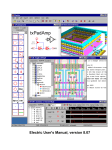
The waveform window looks like the picture below. Note that there is a side bar with a cell explorer in the
window, just like in all windows, but the explorer has a "SIGNALS" section that lists the signals found in the
simulation (and optionally a "SWEEPS" section if swept data was found). When reading HSpice data, the
signals and sweeps sections may be further qualified by analysis, for example "TRANS SIGNALS", "DC
SIGNALS", etc.
Panels
The waveform window contains a set of panels, each with one or more signals. There is a "current panel"
which is identified with a thicker vertical axis (the top panel in the above picture). In a panel, signal names
are shown on the left, and their waveform on the right. Above the signal names in each panel are a number of
controls:
Using the Electric VLSI Design System, version 9.04
137