1
V Series
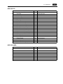
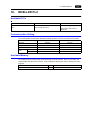
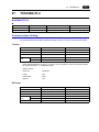
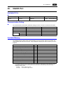
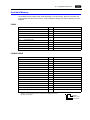
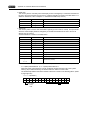
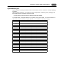
Record of Revisions
Reference numbers are shown at the bottom left corner on the back cover of each manual.
Printing Date
Reference No.
Revised Contents
February, 2004
2200NE0
First edition
October, 2004
2200NE0a
only in PDF file
Preface
Thank you for selecting the MONITOUCH V7 series.
For correct set-up of the V7 series, you are requested to read through this manual to understand more about the
product.
For more information about the V7 series, refer to the following related manuals.
Manual Name
Contents
Reference No.
Reference Manual (Operation)
The V-SFT operating procedure is described.
1043NE
Reference Manual (Function)
The functions and instructions of the V7/V6 series are
explained.
1044NE
V7 Hardware Specifications
Notes on usage and hardware specifications for the
V7 series are described.
2010NE
V706 Hardware Specifications
Notes on usage and hardware specifications for the
V706 are described.
2012NE
Temperature Control Network
The temperature control network function is
explained.
1033NE
Specifications for CC-LINK
Communication Unit
Instructions for CC-LINK are contained.
1028NE
Specifications for PROFIBUS
Communication Unit
Instructions for PROFIBUS are contained.
1036NE
Connection with AB Control Logix
The connection, communication parameters and tag
setting for AB Control Logix are explained.
1041NE
M-CARD SFT Operation Manual
The operating procedure of the memory card editor is
described.
1023NE
V-SFT Additional Specifications
Additional specifications for the Reference Manual are
explained.
5044NE
Ladder Monitor Specifications
Instructions for the ladder monitor function are
contained.
1045NE
For further details about PLCs (programmable logic controllers), see the manual attached to each PLC.
Notes:
1. This manual may not, in whole or in part, be printed or reproduced without the prior written consent of
Hakko Electronics Co., Ltd.
2. The information in this manual is subject to change without prior notice.
3. Windows and Excel are registered trademarks of Microsoft Corporation in the United States and other
countries.
4. All other company names or product names are trademarks or registered trademarks of their
respective holders.
5. This manual is intended to give accurate information about MONITOUCH hardware. If you have any
questions, please contact your local distributor.
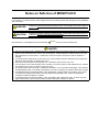
Notes on Safe Use of MONITOUCH
In this manual, you will find various notes categorized under the following levels with the signal words “DANGER,”
and “CAUTION.”
DANGER
Indicates an imminently hazardous situation which, if not avoided, will result in death or
serious injury.
CAUTION
Indicates a potentially hazardous situation which, if not avoided, may result in minor or
moderate injury and could cause property damage.
Note that there is a possibility that the item listed with
CAUTION
may have serious ramifications.
DANGER
• Never use the input function of MONITOUCH for operations that may threaten human life or to damage the
system, such as switches to be used in case of emergency. Please design the system so that it can cope
with malfunction of a touch switch. A malfunction of the touch switch will result in machine accident or
damage.
• Turn off the power supply when you set up the unit, connect cables or perform maintenance and inspection.
Otherwise, electrical shock or damage may occur.
• Never touch any terminals while the power is on. Otherwise, electric shock may occur.
• You must put a cover on the terminals on the unit when you turn the power on and operate the unit. Without
the terminal cover in place, an electric shock may occur.
• The liquid crystal in the LCD panel is a hazardous substance. If the LCD panel is damaged, never swallow
the leaked liquid crystal. If the liquid crystal spills on your skin or clothing, use soap and wash off thoroughly.
• For MONITOUCH using a lithium battery, never disassemble, recharge, deform by pressure, short-circuit,
nor reverse the polarity of the battery, and never dispose of the battery in fire. Failure to follow these
conditions will lead to explosion or ignition.
• For MONITOUCH using a lithium battery, never use a battery that is deformed, leaks, or shows any other
signs of abnormality. Failure to follow these conditions will lead to explosion or ignition.
CAUTION
• Check the appearance of the unit when it is unpacked. Do not use the unit if any damage or deformation is
found. Failure to do so may lead to fire, damage or malfunction.
• For use in a facility or for a system related to nuclear energy, aerospace, medical, traffic equipment, or
mobile installations, please consult your local distributor.
• Operate (or store) MONITOUCH under the conditions indicated in this manual and related manuals. Failure
to do so could cause fire, malfunction, physical damage or deterioration.
• Understand the following environmental limits for use and storage of MONITOUCH. Otherwise, fire or
damage to the unit may result.
- Avoid locations where there is a possibility that water, corrosive gas, flammable gas, solvents, grinding
fluids or cutting oil can come into contact with the unit.
- Avoid high temperature, high humidity, and outside weather conditions, such as wind, rain or direct
sunlight.
- Avoid locations where excessive dust, salt, and metallic particles are present.
- Avoid installing the unit in a location where vibration or physical shock may be transmitted.
• Equipment must be correctly mounted so that the main terminal of MONITOUCH will not be touched
inadvertently. Otherwise, an accident or electric shock may occur.
• Tighten the fixtures of the MONITOUCH with a torque in the specified range. Excessive tightening may
distort the panel surface. Loose tightening may cause MONITOUCH to come off, malfunction or be
short-circuited.
• Check periodically that terminal screws on the power supply terminal block and fixtures are firmly tightened.
Loosened screws may result in fire or malfunction.
• Tighten terminal screws on the power supply terminal block equally to a torque of 0.5 N•m. Improper
tightening of screws may result in fire, malfunction, or trouble.
• MONITOUCH has a glass screen. Do not drop or give physical shock to the unit. Otherwise, the screen
may be damaged.
• Connect the cables correctly to the terminals of MONITOUCH in accordance with the specified voltage and
wattage. Over-voltage, over-wattage or incorrect cable connection could cause fire, malfunction or damage
to the unit.
• Be sure to establish a ground of MONITOUCH. Ground FG terminal which must be used for the unit.
Otherwise, electric shock or a fire may occur.
• Prevent any conductive particles from entering into MONITOUCH. Failure to do so may lead to fire, damage
or malfunction.
• After wiring is finished, remove the paper used as a dust cover before starting to operate MONITOUCH.
Operation with the cover attached may result in accident, fire, malfunction, or trouble.
• Do not attempt to repair MONITOUCH at your site. Ask Hakko or the designated contractor for repair.
• Do not disassemble or modify MONITOUCH. Otherwise, it may cause a malfunction.
• Hakko Electronics Co., Ltd. is not responsible for any damages resulting from repair, overhaul or
modification of MONITOUCH that was performed by an unauthorized person.
• Do not use a sharp-pointed tool when pressing a touch switch. Doing so may damage the screen.
• Only experts are authorized to set up the unit, connect the cables or perform maintenance and inspection.
• For MONITOUCH using a lithium battery, handle the battery with care. The combustible materials such as
lithium or organic solvent contained in the battery may generate heat, explode, or catch fire, resulting in
personal injury or fire. Read related manuals carefully and handle the lithium battery correctly as instructed.
• When using a MONITOUCH that has analog switch resolution with resistance film, do not press two or more
points on the screen at the same time. If there is a switch between the two pressed points, it may be
activated.
• Take safety precautions during such operations as setting change during running, forced output, start, and
stop. Any misoperation may cause unexpected machine motions, resulting in machine accident or damage.
• In facilities where a failure of MONITOUCH could lead to accident threatening human life or other serious
damage, be sure that the facilities are equipped with adequate safeguards.
• At the time of disposal, MONITOUCH must be treated as industrial waste.
• Before touching MONITOUCH, discharge static electricity from your body by touching grounded metal.
Excessive static electricity may cause malfunction or trouble.
[General Notes]
• Never bundle control cables and input/output cables with high-voltage and large-current carrying cables such
as power supply cables. Keep these cables at least 200 mm away from the high-voltage and large-current
carrying cables. Otherwise, malfunction may occur due to noise.
• Plug connectors or sockets of MONITOUCH in the correct orientation. Otherwise, it may cause a malfunction.
• Do not use thinners for cleaning because they may discolor the MONITOUCH surface. Use alcohol or benzine
commercially available.
• If a data receive error occurs when MONITOUCH and the counterpart (PLC, temperature controller, etc.) are
started at the same time, read the manual for the counterpart unit and handle the error correctly.
• Avoid discharging static electricity on the mounting panel of the MONITOUCH. Static charges can damage the
unit and cause malfunctions. Otherwise, malfunction may occur due to noise.
• Avoid prolonged display of any fixed pattern. Due to the characteristics of the liquid crystal display, an
afterimage may occur. If a prolonged display of a fixed pattern is expected, use the auto OFF function of the
backlight.
Contents
Preface
Notes on Safe Use of MONITOUCH
1.
Before Connecting to PLC
Types of Connection............................................................................................................................ 1-1
Interface............................................................................................................................................... 1-5
Wiring (1 : 1 Connection) .................................................................................................................... 1-8
V-SFT Setting (1 : 1 Connection) ...................................................................................................... 1-10
2.
Allen-Bradley PLC
Available PLCs .................................................................................................................................... 2-1
Communication Setting ....................................................................................................................... 2-1
Available Memory ................................................................................................................................ 2-2
PLC-5 Series: Switch Setting .............................................................................................................. 2-3
SLC500 Series, Micro Logix 100: Transmission Parameter Setting.................................................... 2-5
Wiring .................................................................................................................................................. 2-6
3.
Automationdirect PLC
Available PLCs .................................................................................................................................... 3-1
Communication Setting ....................................................................................................................... 3-1
Available Memory ................................................................................................................................ 3-2
Wiring .................................................................................................................................................. 3-2
4.
Baldor PLC
Available PLCs .................................................................................................................................... 4-1
Communication Setting ....................................................................................................................... 4-1
Available Memory ................................................................................................................................ 4-1
Wiring .................................................................................................................................................. 4-2
5.
DELTA PLC
Available PLCs .................................................................................................................................... 5-1
Communication Setting ....................................................................................................................... 5-1
Available Memory ................................................................................................................................ 5-1
Wiring .................................................................................................................................................. 5-2
6.
FANUC PLC
Available PLCs .................................................................................................................................... 6-1
Communication Setting ....................................................................................................................... 6-1
Available Memory ................................................................................................................................ 6-1
Wiring .................................................................................................................................................. 6-2
7.
FATEK AUTOMATION PLC
Available PLCs .................................................................................................................................... 7-1
Communication Setting ....................................................................................................................... 7-1
Available Memory ................................................................................................................................ 7-1
Wiring .................................................................................................................................................. 7-2
8.
Fuji Electric PLC
Available PLCs .................................................................................................................................... 8-1
Communication Setting ....................................................................................................................... 8-1
MICREX-F Series, SPB (N Mode) & FLEX-PC Series: Switch Setting ............................................... 8-2
Available Memory ................................................................................................................................ 8-3
Wiring .................................................................................................................................................. 8-5
9.
GE Fanuc PLC
Available PLCs .................................................................................................................................... 9-1
Communication Setting ....................................................................................................................... 9-1
Available Memory ................................................................................................................................ 9-2
Wiring .................................................................................................................................................. 9-3
10.
Hitachi PLC
Available PLCs ..................................................................................................................................
Communication Setting .....................................................................................................................
HIDIC-H: Switch Setting ....................................................................................................................
Available Memory ..............................................................................................................................
Wiring ................................................................................................................................................
11.
IDEC PLC
Available PLCs ..................................................................................................................................
Communication Setting .....................................................................................................................
Available Memory ..............................................................................................................................
Wiring ................................................................................................................................................
12.
14-1
14-1
14-2
14-4
Matsushita Electric Works PLC
Available PLCs ..................................................................................................................................
Communication Setting .....................................................................................................................
MEWNET: Link Unit Switch Setting...................................................................................................
Available Memory ..............................................................................................................................
Wiring ................................................................................................................................................
16.
13-1
13-2
13-2
13-3
13-5
LG PLC
Available PLCs ..................................................................................................................................
Communication Setting .....................................................................................................................
Available Memory ..............................................................................................................................
Wiring ................................................................................................................................................
15.
12-1
12-2
12-4
12-5
KOYO ELECTRONICS PLC
Available PLCs ..................................................................................................................................
Communication Setting .....................................................................................................................
Available Memory ..............................................................................................................................
Switch Setting....................................................................................................................................
Wiring ................................................................................................................................................
14.
11-1
11-1
11-1
11-2
KEYENCE PLC
Available PLCs ..................................................................................................................................
Communication Setting .....................................................................................................................
Available Memory ..............................................................................................................................
Wiring ................................................................................................................................................
13.
10-1
10-1
10-2
10-2
10-4
15-1
15-1
15-2
15-2
15-3
MITSUBISHI ELECTRIC PLC
Available PLCs .................................................................................................................................. 16-1
Communication Setting ..................................................................................................................... 16-3
A Series Link, QnA Series Link: Switch Setting ................................................................................ 16-5
Available Memory .............................................................................................................................. 16-6
Wiring ................................................................................................................................................ 16-8
A Link + Net10................................................................................................................................. 16-13
V-MDD (Dual Port Interface) ........................................................................................................... 16-15
Ladder Transfer Function ................................................................................................................ 16-15
17.
MODICON PLC
Available PLCs ..................................................................................................................................
Communication Setting .....................................................................................................................
Available Memory ..............................................................................................................................
Wiring ................................................................................................................................................
18.
MOELLER PLC
Available PLCs ..................................................................................................................................
Communication Setting .....................................................................................................................
Available Memory ..............................................................................................................................
Wiring ................................................................................................................................................
19.
17-1
17-1
17-1
17-2
18-1
18-1
18-1
18-2
OMRON PLC
Available PLCs ..................................................................................................................................
Communication Setting .....................................................................................................................
Available Memory ..............................................................................................................................
Wiring ................................................................................................................................................
SYSMAC CS1/CJ1 DNA ...................................................................................................................
19-1
19-2
19-3
19-4
19-8
20.
SAIA PLC
Available PLCs .................................................................................................................................. 20-1
Communication Setting ..................................................................................................................... 20-1
S-BUS Configuration ......................................................................................................................... 20-1
Available Memory .............................................................................................................................. 20-1
Wiring ................................................................................................................................................ 20-2
21.
SAMSUNG PLC
Available PLCs .................................................................................................................................. 21-1
Communication Setting ..................................................................................................................... 21-1
Available Memory .............................................................................................................................. 21-1
Wiring ................................................................................................................................................ 21-2
22.
SHARP PLC
Available PLCs .................................................................................................................................. 22-1
Communication Setting ..................................................................................................................... 22-1
JW Series: Link Unit Switch Setting .................................................................................................. 22-1
JW100/70H COM Port, JW20 COM Port: System Memory Setting .................................................. 22-2
Available Memory .............................................................................................................................. 22-2
Wiring ................................................................................................................................................ 22-3
23.
SHINKO ELECTRIC PLC
Available PLCs .................................................................................................................................. 23-1
Communication Setting ..................................................................................................................... 23-1
Available Memory .............................................................................................................................. 23-1
Wiring ................................................................................................................................................ 23-2
24.
Siemens PLC
Available PLCs .................................................................................................................................. 24-1
Communication Setting ..................................................................................................................... 24-1
Available Memory .............................................................................................................................. 24-4
Wiring ................................................................................................................................................ 24-7
25.
TAIAN PLC
Available PLCs .................................................................................................................................. 25-1
Communication Setting ..................................................................................................................... 25-1
Available Memory .............................................................................................................................. 25-1
Wiring ................................................................................................................................................ 25-2
26.
Telemecanique PLC
Available PLCs .................................................................................................................................. 26-1
Communication Setting ..................................................................................................................... 26-1
Available Memory .............................................................................................................................. 26-1
Wiring ................................................................................................................................................ 26-2
27.
TOSHIBA PLC
Available PLCs .................................................................................................................................. 27-1
Communication Setting ..................................................................................................................... 27-1
Available Memory .............................................................................................................................. 27-2
Wiring ................................................................................................................................................ 27-3
28.
TOSHIBA MACHINE PLC
Available PLCs .................................................................................................................................. 28-1
Communication Setting ..................................................................................................................... 28-1
Available Memory .............................................................................................................................. 28-1
Wiring ................................................................................................................................................ 28-2
29.
Toyoda Machine Works PLC
Available PLCs .................................................................................................................................. 29-1
Communication Setting ..................................................................................................................... 29-1
Switch Setting.................................................................................................................................... 29-1
Available Memory .............................................................................................................................. 29-2
Screen Editing (Memory Input) .......................................................................................................... 29-2
Wiring ................................................................................................................................................ 29-3
30.
VIGOR PLC
Available PLCs .................................................................................................................................. 30-1
Communication Setting ..................................................................................................................... 30-1
Available Memory .............................................................................................................................. 30-1
Wiring ................................................................................................................................................ 30-2
31.
Yamatake PLC
Available PLCs ..................................................................................................................................
Communication Setting .....................................................................................................................
Available Memory ..............................................................................................................................
Wiring ................................................................................................................................................
32.
Yaskawa Electric PLC
Available PLCs ..................................................................................................................................
Communication Setting .....................................................................................................................
Available Memory ..............................................................................................................................
Wiring ................................................................................................................................................
33.
31-1
31-1
31-1
31-2
32-1
32-1
32-2
32-3
Yokogawa Electric PLC
Available PLCs ..................................................................................................................................
Communication Setting .....................................................................................................................
Available Memory ..............................................................................................................................
Wiring ................................................................................................................................................
Appendix 1
33-1
33-2
33-3
33-4
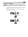
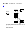
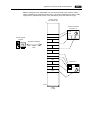
PLC2Way
PLC2Way ..................................................................................................................................... App1-1
Limitations on Connection at PLC2Way ....................................................................................... App1-2
PLCs Compatible with PLC2Way Connection at MJ Port ............................................................ App1-3
Wiring ........................................................................................................................................... App1-4
V-SFT Setting: System Setting..................................................................................................... App1-6
V-SFT Setting
When the Temperature Control Network/PLC2Way Table is Used:........................................... App1-10
Indirect Memory Designation...................................................................................................... App1-17
User Log Read for YOKOGAWA’s PLC ..................................................................................... App1-17
Processing Cycle........................................................................................................................ App1-18
Notes on Screen Data Transfer.................................................................................................. App1-19
System Memory ......................................................................................................................... App1-20
Appendix 2
n : 1 Connection (Multi-link 2)
Multi-link 2 ....................................................................................................................................
Wiring ...........................................................................................................................................
V-SFT Setting ...............................................................................................................................
Communication Error ...................................................................................................................
Appendix 3
App2-1
App2-2
App2-6
App2-7
n : 1 Connection (Multi-link)
Multi-link ....................................................................................................................................... App3-1
Wiring ........................................................................................................................................... App3-2
V-SFT Setting ............................................................................................................................... App3-5
Appendix 4
1 : n Connection (Multi-drop)
1 : n Connection ...........................................................................................................................
Wiring (RS-422/485).....................................................................................................................
V-SFT Setting ...............................................................................................................................
Notes on Communication Errors ..................................................................................................
Appendix 5
App4-1
App4-2
App4-2
App4-3
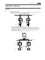
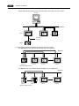
Ethernet
Ethernet ........................................................................................................................................ App5-1
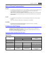
Notes on Ethernet Communications............................................................................................. App5-3
IP Address for the V7 Series ........................................................................................................ App5-3
Communication Interface Unit CU-03-2 ....................................................................................... App5-3
Option Unit DU-01 ........................................................................................................................ App5-5
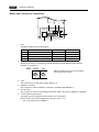
Wiring ........................................................................................................................................... App5-6
Transferring Screen Data ............................................................................................................. App5-9
V-SFT Setting: PLC Type/Communication Parameter ............................................................... App5-12
V-SFT Setting: Network Table Editing........................................................................................ App5-16
V-SFT Setting: Macro ................................................................................................................. App5-21
System Memory ......................................................................................................................... App5-24
Ethernet Access Functions (HKEtn10.DLL) ............................................................................... App5-28
Server Communication Procedure ............................................................................................. App5-41
Error Display ............................................................................................................................... App5-42
Appendix 6
Universal Serial Communications
Interface ....................................................................................................................................... App6-1
System Setting ........................................................................................................................... App6-14
Standard Type Protocol.............................................................................................................. App6-21
1-byte Character Code List ........................................................................................................ App6-43
Memory Map .............................................................................................................................. App6-44
Appendix 7
V-Link
V-Link ........................................................................................................................................... App7-1
Wiring ........................................................................................................................................... App7-2
V-SFT Setting ............................................................................................................................... App7-4
Protocol ........................................................................................................................................ App7-5
NAK: Error Codes......................................................................................................................... App7-9
1-byte Character Code List......................................................................................................... App7-10
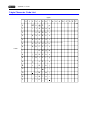
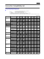
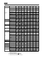
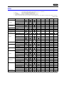
Connection Compatibility List
V712/V710/V708/V706+DU-01........................................................................................................ List-1
V706 ................................................................................................................................................ List-3
1. Before Connecting to PLC
1.
1-1
Before Connecting to PLC
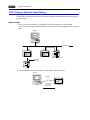
Types of Connection
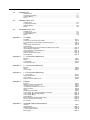
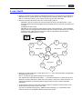
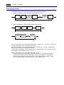
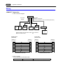
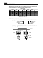
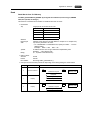
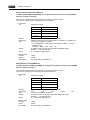
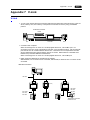
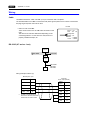
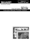
There are four types of connection between MONITOUCH(es) and PLC(s).
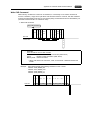
1 : 1 Connection
Outline
One set of the V7 series is connected to one PLC (1 : 1 connection).
The wiring diagrams and the description of settings for connection to PLCs in 1 : 1 connections can be
found from Chapter 2 onward.
V7 series
PLC
CN1
RS-232C or RS-422 (RS-485)
The host link unit of the PLC or the CPU port is used and the V7 series (master station) establishes
communications according to the protocol of the PLC. Consequently, it is not necessary to have the
dedicated communication program on the PLC (slave station). The V7 series reads the PLC memory
for screen display. It is also possible to write switch data or numerical data entered through the keypad
directly to the PLC memory.
V7 series
PLC
Read
Write
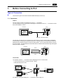
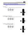
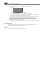
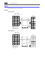
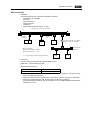
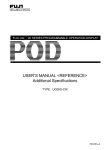
Connection
The interface used for 1 : 1 connection varies depending on the V7 series model.
• CN1 (D-sub 25-pin) for V7 series and V706 + DU-01
• MJ2 (RJ-45 8-pin) for V706
V7 series
PLC
CN1
RUN
STOP
...
...
...
...
...
...
...
...
...
...
...
...
...
...
...
...
V706
MJ2
CN1
V706 + DU-01
For details on wiring and settings for 1 : 1 connection, refer to page 1-8.
1-2
1. Before Connecting to PLC
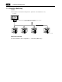
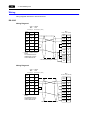
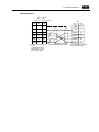
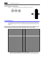
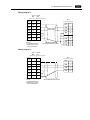
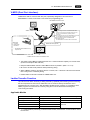
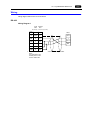
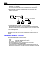
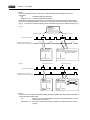
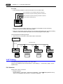
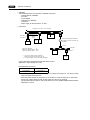
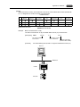
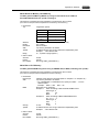
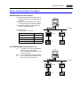
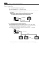
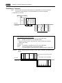
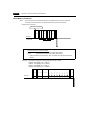
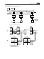
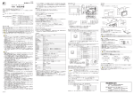
1 : n Connection (Multi-drop)
Outline
One V7 series is connected to multiple PLCs. (Maximum connectable PLCs: 31)
V7 series
CN1
Maximum length (V7 series to the terminating PLC) = 500 m
RS-422/RS-485 connection
PLC1
PLC2
PLC3
Notes on Connection
For more information, refer to “Appendix 4, 1 : n Connection (Multi-drop).”
PLCn (n = 1 to 31)
1-3
1. Before Connecting to PLC
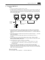
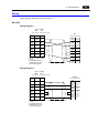
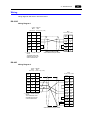
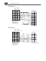
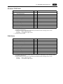
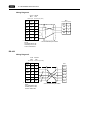
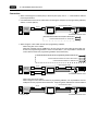
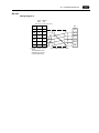
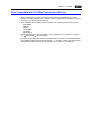
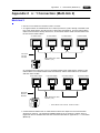
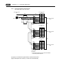
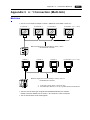
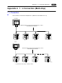
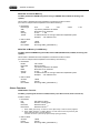
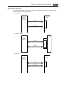
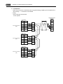
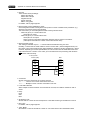
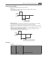
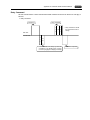
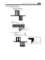
n : 1 Connection (Multi-link 2)
Outline
• One PLC is connected to a maximum of four V7 series.
• An original network is created where the V7 series (Local Port 1) that is directly connected to the
PLC is the master station, and other three V7 series are slave stations. Only the master station
makes communications directly with the PLC, and the slave stations make communications with
the PLC via the master station.
V7 master station
V7 slave station
V7 slave station
V7 slave station
Local port 1
Local port 2
Local port 3
Local port 4
CN1
CN1
CN1
CN1
MJ2
RS-232C
RS-422
RS-485
Hakko Electronics’ cable
“V6-MLT” (3 m)
RS-485 connection
PLC
• Communications between the V7 master station and the PLC depend on the communication
speed set on the PLC. The maximum available speed for the V7 series is 115 kbps, which is
higher than the one available with multi-link connection described in “n : 1 Connection (Multi-link)”
(page 1-4).
• This multi-link connection is available with almost all the PLC models that support 1 : 1 connection
(refer to the “Appendix”).
The connection between the master station and the PLC is the same as the one for 1 : 1
connection.
• Use the RS-485 2-wire connection between stations of the V7 series. Please use Hakko
Electronics’ multi-link 2 master cable (V6-MLT) for connection between the master station (Local
Port 1) and the slave station (Local Port 2).
• In the following cases, multi-link 2 connection is not available.
1. A communication interface unit (example: OPCN-1, CC-LINK, Ethernet, etc.) is used.
2. The V6 series (master or slave station) is used for the temperature control network or
PLC2Way function.
• The V7 and V6 series can be used together. The V6 series can be the master station.
(However, when V606/V606i is the master station, the slave station must be V606/V606i. Also,
depending on the hardware version of the V6 series, multi-link 2 connection may not be supported.
Refer to the V6 Hardware Specifications.)
Notes on Connection
For more information, refer to “Appendix 2, n : 1 Connection (Multi-link 2).”
1-4
1. Before Connecting to PLC
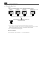
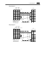
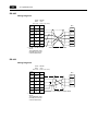
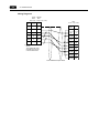
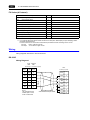
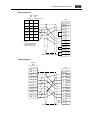
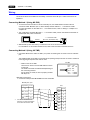
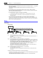
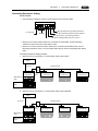
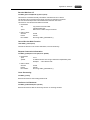
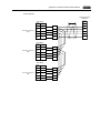
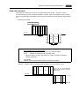
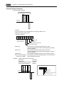
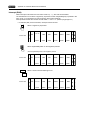
n : 1 Connection (Multi-link)
Outline
• One PLC is connected to multiple V7 series. (Maximum connectable V series: 31)
V7 series No. 1
V7 series No. 2
V7 series No. 3
CN1
CN1
CN1
V7 series No. “n” (n = 1 to 31)
CN1
Maximum length (PLC to the terminating V7 series) = 500 m
RS-422/RS-485 connection
PLC
• The PLC must be of the type of signal level RS-422/RS-485 with port numbers.
For the available PLC models, refer to “Connection Compatibility List” at the back of this manual.
RS-422 connection between the V7 series ↔ PLC must be in 2-wire connection.
• The V7 and V6 series can be used together.
Notes on Connection
For more information, refer to “Appendix 3, n : 1 Connection (Multi-link).”
1-5
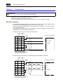
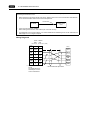
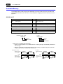
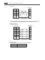
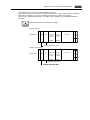
1. Before Connecting to PLC
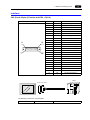
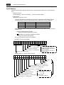
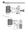
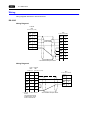
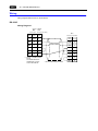
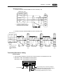
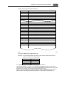
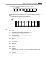
Interface
CN1 (D-sub 25-pin) (V7 series and V706 + DU-01)
CN1 (D-sub 25-pin, female)
Pin No.
Signal Name
Contents
1
FG
Frame ground
2
SD
RS-232C send data
3
RD
RS-232C receive data
4
RS
RS-232C RS request to send
5
CS
RS-232C CS clear to send
6
7
Not used
SG
Signal ground
9
+5 V
Use prohibited
10
0V
Use prohibited
+SD
RS-422 send data (+)
8
14
25
Not used
11
12
1
13
Not used
13
−SD
RS-422 send data (−)
14
+RS
RS-422 RS send data (+)
15
Not used
16
17
Not used
−RS
RS-422 RS send data (−)
18
−CS
RS-422 CS receive data (−)
19
+CS
RS-422 CS receive data (+)
21
−
Use prohibited (V708: not used)
22
−
Use prohibited (V708: not used)
24
+RD
RS-422 receive data (+)
25
−RD
RS-422 receive data (−)
20
Not used
23
Not used
PLC
D-sub 25-pin (male)
The following connector is recommended.
Recommended connector
DDK-make 17JE23250-02 (D8A)
D-sub 25-pin, male, metric thread, with hood
1-6
1. Before Connecting to PLC
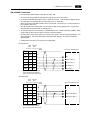
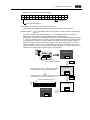
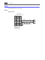
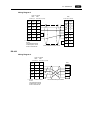
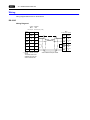
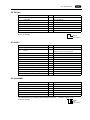
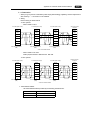
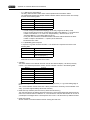
MJ2 (V706 only)
MJ2
Pin No.
1 *1
2 *1
12345678
3
4
5
6
7 *1
8 *1
*1
*2
Signal Name
Contents
Not used
Not used
+SD
RS-422 + send data
Not used
Not used
−SD
RS-422 − send data
+5 V
Externally supplied +5 V
Max. 150 mA *2
SG
Signal ground
RD
RS-232C receive data
+RD
RS-422 + receive data
SD
RS-232C send data
-RD
RS-422 − receive data
Switch between RS-232C and RS-422 for pin Nos. 1, 2, 7, and 8 with the slide switch on the MONITOUCH.
For more information, refer to “Slide Switch.”
The maximum current for the output power supply (+5 V) is 150 mA when MJ1 or MJ2 is used.
Pin arrangement on
the MONITOUCH Pin arrangement
on the cable
12345678
PLC
87654321
* The pin arrangement shown above assumes
the cable is viewed as shown in the figure.
RJ-45 8-pin
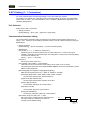
Slide Switch
• Whether MJ2 is used as an RS-232C or RS-422 (4-wire) port is selected with the slide switch.
Before connecting a V706 to a PLC, check that the switch is set to the correct side.
• The slide switch is adjacent to the DIP switch on the side of the V706.
The switch is factory-set to RS-422. When RS-422 is selected, the slide switch is in the lower
position. To select RS-232C, slide the switch to the upper position.
Side View
Slide switch
Lower position: RS-422 (4-wire)
Upper position: RS-232C
1-7
1. Before Connecting to PLC
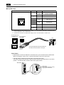
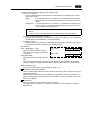
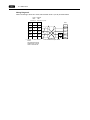
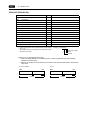
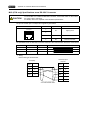
Connection between MJ2 and PLC
There are two connection methods.
• With MJ2-PLC
One method uses an adaptor MJ2-PLC for connection between MJ2 and the D-sub 25-pin
connector plus a PLC communication cable.
For connection of a PLC communication cable, refer to the CN1 pin arrangement.
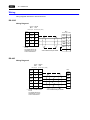
Example: Connecting to MITSUBISHI A1SJ71UC24-R2
V series PLC communication cable
D-sub 25-pin (male)
MJ2-PLC
MJ2
FG
1
PLC
D-sub 9-pin (male)
SD
2
CD
1
RD
3
RD
2
RS
4
SD
3
CS
5
SG
5
SG
7
DR
6
RS
7
CS
8
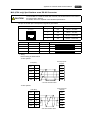
• With V6-TMP
Refer to the PLC wiring diagram and the MJ2 pin arrangement.
Example: Connecting to MITSUBISHI A1SJ71UC24-R2
MJ2
RJ-45 8-pin
SG SHELL
V6-TMP
PLC
D-sub 9-pin (male)
SD
8
CD
1
RD
7
RD
2
SG
5
SD
3
SG
5
DR
6
RS
7
CS
8
1-8
1. Before Connecting to PLC
Wiring (1 : 1 Connection)
Electric shock hazard
Shut the power off before connecting cables.
DANGER
Prepare the communication cable with the PLC on your side.
Refer to the following information for the cable.
For more information on the connection to respective PLCs, refer to “Chapter 2” and later.
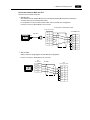
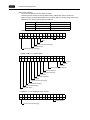
RS-232C Connection
• Connect the shielded cable either to the V7 series or PLC side. This connection diagram shows
the case where the shielded cable is connected on the V7 series side.
When connecting the shielded cable to the V7 series side, connect it to pin 1 of the connector or
the connector case cover.
The metal shell of the modular jack 2 on the V706 is used as SG (signal ground). Connect the
shielded cable to the metal shell of modular jack 2.
• Twisted pairs of 0.3 mm sq. or above are recommended.
V706 V Series
MJ2
CN1
RJ-45 8-pin
Signal
Name
D-sub 25-pin (male)
To the PLC’s RS-232C port
Shield
Pin No. Pin No.
*1
SHELL
1
SD
8
2
Receive data
RD
7
3
Send data
RS
4
CS
5
SG
5
7
SG
*1 Pin No. 1 of CN1 is used as FG.
The metal shell of the modular jack
2 on the V706 is used as SG.
• If noise disturbs communications, use twisted pairs between SD/SG and RD/SG.
V706 V Series
MJ2
CN1
RJ-45 8-pin
D-sub 25-pin (male)
Shield
To the PLC’s RS-232C port
Signal
Name
Pin No.
Pin No.
*1
SHELL
1
SD
8
2
RD
7
3
SG
RS
4
Send data
CS
5
SG
5
7
*1 Pin No. 1 of CN1 is used as FG.
The metal shell of the modular jack
2 on the V706 is used as SG.
Receive data
SG
1. Before Connecting to PLC
1-9
RS-422/485 Connection
• Connect twisted pairs between +SD/−SD and +RD/−RD.
• If the PLC has the terminal for signal ground (SG), be sure to connect a wire.
• Connect the shielded cable either to the V7 series or PLC side. This connection diagram shows
the case where the shielded cable is connected on the V7 series side.
When connecting the shielded cable to the V7 series side, connect it to pin 1 of the connector or
the connector case cover.
The metal shell of the modular jack 2 on the V706 is used as SG (signal ground). Connect the
shielded cable to the metal shell of modular jack 2.
• To use a terminal block for connection, use Hakko Electronics’ “TC485” optionally available. When
using TC485 on the V706, the option unit DU-01 must be installed.
• The DIP switch on the side or back of V7 series units is used to set the terminating resistors. For
more information, refer to the description of the DIP switch setting in the relevant Hardware
Specifications.
• Twisted pairs of 0.3 mm sq. or above are recommended.
<4-wire system>
V706 V Series
MJ2
CN1
RJ-45 8-pin
D-sub 25-pin (male)
Shield
To the PLC’s RS-422 port
Signal
Name
Pin No.
Pin No.
*1
SHELL
1
SG
5
7
+SD
1
12
Receive data (+)
-SD
2
13
Receive data (−)
+RD
7
24
Send data (+)
-RD
8
25
Send data (−)
SG
*1 Pin No. 1 of CN1 is used as FG.
The metal shell of the modular
jack 2 on the V706 is used as SG.
<2-wire system>
V706 V Series
MJ2
CN1
RJ-45 8-pin
D-sub 25-pin (male)
Shield
To the PLC’s RS-422 port
Signal
Name
Pin No.
Pin No.
*1
SHELL
1
SG
5
7
+SD
1
12
Send/receive data (+)
-SD
2
13
Send/receive data (−)
+RD
7
24
-RD
8
25
*1 Pin No. 1 of CN1 is used as FG.
The metal shell of the modular
jack 2 on the V706 is used as SG.
SG
1-10
1. Before Connecting to PLC
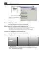
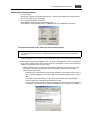
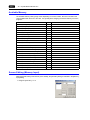
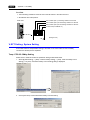
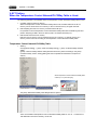
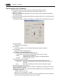
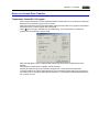
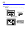
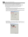
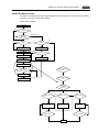
V-SFT Setting (1 : 1 Connection)
For serial communications, the following settings on the V-SFT editor are required.
The settings in the [Select PLC Type] and [Comm. Parameter] dialogs are shown on the Main Menu
screen of the V7 series. (For more information, refer to “Chapter 6, MONITOUCH Operations” in V7
Hardware Specifications.)
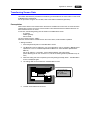
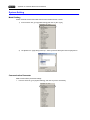
PLC Selection
Select the PLC that is connected.
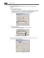
• Setting Procedure
[System Setting] → [PLC Type] → [Select PLC Type] dialog
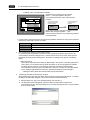
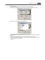
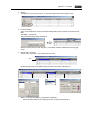
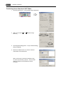
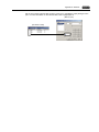
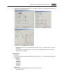
Communication Parameter Setting
The communication parameter setting is essential for successful communications between the V7
series ↔ PLC. Check the communication parameter setting on the PLC before making the setting on
MONITOUCH.
• Setting Procedure
[System Setting] → [Comm. Parameter] → [Comm. Parameter] dialog
• Setting Items
[Connection] (1 : 1 / 1 : n / Multi-Link / Multi-Link 2)
Select the type of connection between the V7 series and the PLC. There are four types
available. Depending on the selected type, the setting items in the [Comm. Parameter] dialog
or those for the memory vary.
Select [1 : 1] for 1 : 1 connection.
[Local No.]
Set the port number of the PLC.
[Trans. Mode] (Trans. Mode 1 / Trans. Mode 4)
When the PLC has a transmission mode setting, set the same on the V7 series.
This setting must be used for PLCs of MITSUBISHI, OMRON, HITACHI, YOKOGAWA, Toyoda
Machinery and YASKAWA.
[Baud Rate] [Signal Level] [Data Length] [Stop Bit] [Parity]
Make the same setting as the PLC. (Refer to “Chapter 2” and later.)
[Baud Rate] (4800, 9600, 19200, 38400, 57600, 76800, 115 kbps)
Set the same communication speed as the PLC.
[Signal Level] (RS-232C/RS-422)
Set the same communication interface as the PLC.
[Data Length] (7-bit/8-bit)
Choose either data length for communication.
[Stop Bit] (1-bit/2-bit)
Choose either stop bit for communication.
[Parity] (None/Odd/Even)
Choose any of the parity options for communication.
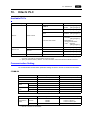
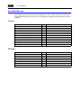
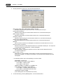
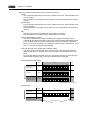
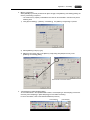
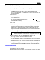
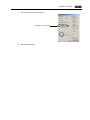
[Send Delay Time] (0 to 255) (Unit: ×1 msec)
Set a time delay in sending the next command to the
PLC after receipt of a response from the PLC.
Normally use the default setting.
PLC
MONITOUCH
Send delay
time “t”
1-11
1. Before Connecting to PLC
Choose the action to be taken against communication errors.
[Comm. Err. Handling]
Set error handling routine in the case that a communication error between the V7 series
and the PLC occurs.
[Stop]
If any communication error has arisen, the communications are stopped.
When restoring, use the Retry switch (found on the error screen of the V7
series).
[Continuous] If any communication error has arisen, it is indicated at the top left corner
on the V7 screen. The V7 series conducts polling of the PLC, and if OK,
the error state is automatically reset.
Supplemental Information:
Polling
“Polling” means to constantly monitor and check the state of the other station.
[Time-out Time] (0 to 999) (Unit: ×10 msec)
Specify a time for monitoring the receiving of a response from the PLC. If no response is
received within the specified time, a retrial is attempted.
[Retrials] (1 to 255)
Specify the number of retrial times. When the problem persists even after as many retrials
as specified, the system will start the error handling routine.
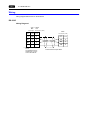
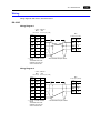
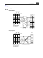
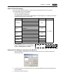
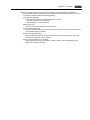
[Text Process]
(LSB → MSB / MSB → LSB)
When processing characters, choose
either option for arranging 1st/2nd bytes
in one word.
15
[LSB → MSB]
0
MSB
LSB
2nd byte
1st byte
MSB
LSB
1st byte
2nd byte
15
[MSB → LSB]
[Code] (DEC/BCD)
0
Choose the code for entering numerical
data.
For some numerical data, such as those for data displays or data sampling in the sampling
mode, this setting is not applied because BCD or DEC should be chosen for [Input Format].
[Read Area] [Write Area]
For more information, refer to “System Memory” (page 1-12).
[
Read/Write Area GD-80 Compatible]
When converting screen data files created on GD-80 into those of the V7 series, this option is
automatically checked.
When this option is checked, GD-80 compatibility is supported by securing 2 words each for
[Read Area] and [Write Area] in the same format as GD-80. For more information, refer to the
GD-80 User’s Manual.
[
Use Ethernet]
When using Ethernet communications, check this option.
For details, refer to “9. Ethernet” in “Chapter 5, Connections” in the separate V7 Hardware
Specifications.
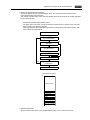
1-12
1. Before Connecting to PLC
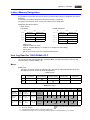
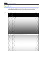
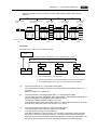
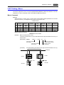
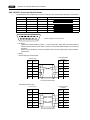
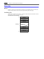
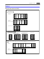
System Memory
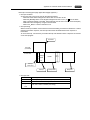
[Read Area] and [Write Area] must be secured for communications between the V7 series and the
PLC.
• Setting Procedure
[System Setting] → [Comm. Parameter] → [Comm. Parameter] dialog
• Setting Items
[Read Area] (3 words or more)*
- This is the area where commands from the PLC are received for screen display changes.
Consecutive three words from the specified memory address are used as “read area.”
Address
Name
Contents
n
RCVDAT
Sub command/data
n+1
SCRN_COM
Screen status command
n+2
SCRN_No
Screen number command
* When you have created screens with the following function, the number of required memory
addresses vary.
• When the sampling function is used:
Refer to the Reference Manual (Function).
• [
Read/Write Area GD-80 Compatible] is checked:
Refer to the GD-80 User’s Manual.
- Set “0” for all the bits not used in the read area.
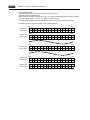
• RCVDAT (n) Sub command/data
15 14 13 12
0
0
0
0
11 10 09 08 07 06 05 04 03 02 01 00
0
0
0
0
0
0
0
0
0
Free
BZ0 ([0 → 1] leading edge)
BZ1 ([0 → 1] leading edge)
System reserved (setting [0])
Calendar setting ([0 → 1] leading edge)
System reserved (setting [0])
To forcibly change the bits for “free”
area, the same data is written to
CFMDATA in [Write Area] after the
screen is displayed.
Use this function for watch dog or
display scanning.
• SCRN_COM (n + 1) Screen status command
15 14 13 12
0
11 10 09 08 07 06 05 04 03 02 01 00
0
0
0
0
0
Overlap 0
Overlap 1
Overlap 2
System reserved (setting [0])
Global macro execution ([0 → 1] leading edge)
Data sheet output ([0 → 1] leading edge)
Screen hard copy ([0 → 1] leading edge)
Backlight (level)
System reserved (setting [0])
Screen internal switching (level)
Screen forced switching ([0 → 1] leading edge)
Data read refresh ([0 → 1] leading edge)
Normal overlap or call-overlap:
0 → 1: ON
1 → 0: OFF
Multi-overlap:
Level (with exceptions)
1. Before Connecting to PLC
1-13
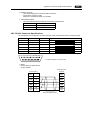
• SCRN_No. (n + 2) Screen number command
15 14 13 12 11
0
0
10 09 08 07 06 05 04 03 02 01 00
0
Screen number
System reserved (setting [0])
Use example: To specify a screen number from the PLC:
When “D0” is set for [Read Area], the screen number is written in “D2” of the PLC.
Problem example: The screen display does not change when a screen number is specified from
the PLC.
If the same number as the one specified for “n + 2” is already contained in this memory
address, the screen display does not change even if it is specified again.
For example, if screen No. 5 is specified from the PLC and it was once changed to screen No.
2 → No. 0 by internal switches, normally it cannot be returned to the former screen No. 5 that
was specified by an external command, because the external screen command number (5)
remains the same as before in the memory address (“D2” in the read area) for the screen
number command. In such a case, it is possible to forcibly switch the screen to the screen
number contained in “D2” in the read area at the leading edge [0 → 1] of bit 14 of the memory
address for the screen status command (“D1” in the read area).
Screen No. 5
D000
D001
D002
5
No. 2
Read area “n + 2”
= Screen number command
Data in the read area “n + 2” remains the same even
if the actual screen has been switched internally.
No. 2
Screen No. 2
No. 0
To show screen No. 5 again using an external screen
command, set [0→1] to bit 14 of read area “n + 1.”
No. 0
Screen forced switching (bit 14)
15
14
13
12
11
10
09
08
07
06
05
04
03
02
01
00
D000
D001 0 1 0 0
D002 0 0 0
0
0
0
0
0
0
5
0
0
0
0
0
0
Screen No. 0
No. 3
Screen No. 5
No. 2
1-14
1. Before Connecting to PLC
[Write Area] (3 words)*
This is an area where the screen status is written.
Consecutive three words from the specified memory address are used as “write area.”
* When you have converted GD-80 data to the V7 series data, the number of required memory
addresses vary. Refer to the GD-80 User’s Manual.
Address
Name
Contents
n
CFMDAT
Same as data in read area “n”
n+1
SCRN_COM
Screen status
n+2
SCRN_No
Displayed screen number
• CFMDAT (n)
15 14 13 12 11
10 09 08 07 06 05 04 03 02 01 00
0
0
0
0
0
0
0
0
0
0
0
0
0
Free
BZ0
BZ1
System reserved (setting [0])
Calendar setting
System reserved (setting [0])
• SCRN_COM (n + 1) Screen status
15 14 13 12
11 10 09 08 07 06 05 04 03 02 01 00
0
0
0
0
0
Overlap 0
Overlap 1
Overlap 2
System reserved (setting [0])
Serial extension I/O
Global macro execution
Printer busy
Print data transferring
Backlight
System reserved (setting [0])
Screen internal switching
Screen forced switching
Data read refresh
• SCRN_No. (n + 2) Displayed screen number
15 14 13 12 11
0
0
10 09 08 07 06 05 04 03 02 01 00
0
Screen number
System reserved (setting [0])
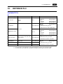
2. Allen-Bradley PLC
2.
2-1
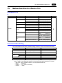
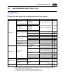
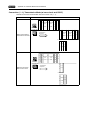
Allen-Bradley PLC
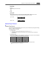
Available PLCs
Select PLC Type
PLC-5
PLC
Unit/Port
RS-232C
[Wiring Diagram 1]
1770-KF2
RS-232C
RS-422
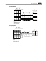
[Wiring Diagram 2]
[Wiring Diagram 6]
CPU (processor module)
RS-232C channel
RS-232C
[Wiring Diagram 3]
1747-KE
RS-232C
RS-422
[Wiring Diagram 4]
[Wiring Diagram 7]
PLC-5
SLC500
Connection
1785-KE
SLC 5/03 and later
Micro Logix 1000
Micro Logix 1000
Port on CPU
A•B’s RS-232C
Ladder transfer cable*1
+
RS-232
[Wiring Diagram 5]
Control Logix
Control Logix 1756 system
Logix5550
*2
*1
*2
When using RS-232C ladder transfer cable made by Allen-Bradley, connect the cable shown in [Wiring
Diagram 3] to the D-sub 9-pin side of the ladder transfer cable for communications with the V7 series.
For more information on connection to A•B Control Logix, refer to “Connection with A•B Control Logix”
separately provided.
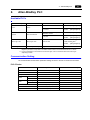
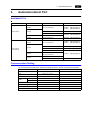
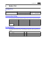
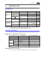
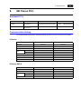
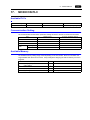
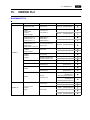
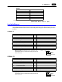
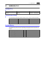
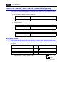
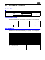
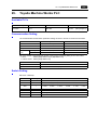
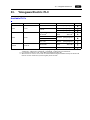
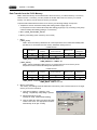
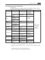
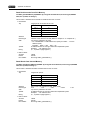
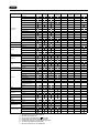
Communication Setting
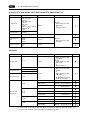
The recommended communication parameter settings of the PLC and the V7 series are as follows:
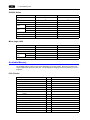
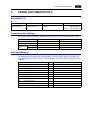
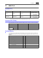
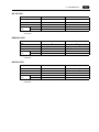
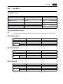
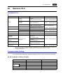
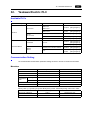
PLC-5 Series
Item
Baud rate
Port
Parity
Setting on PLC
V7 Comm. Parameter Setting
19200 bps
19200 bps
0
0
Even
Even
−
−
1785-KE not supported
−
Transmission
mode
RS-232C
Transmission
code
Data length
8
8
Stop bit
1
1
Full duplex (fixed)
−
BCC (fixed)
−
NO (fixed)
−
Protocol
Error check
Reponse
RS-422
2-2
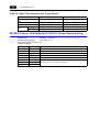
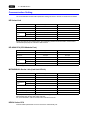
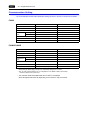
2. Allen-Bradley PLC
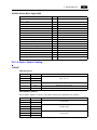
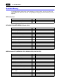
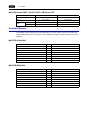
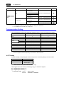
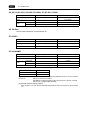
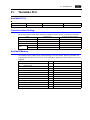
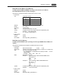
SLC500 Series
Item
Baud rate
Port
Parity
Setting on PLC
V7 Comm. Parameter Setting
19200 bps
19200 bps
0
0
Even
Even
−
−
Channel 0 not supported
−
Transmission
mode
RS-232C
Transmission
code
Data length
8
8
Stop bit
1
1
Full duplex (fixed)
−
BCC (fixed)
−
NO (fixed)
−
Setting on PLC
V7 Comm. Parameter Setting
9600 bps
9600 bps
RS-422
Protocol
Error check
Reponse
Micro Logix 1000
Item
Baud rate
Port
Parity
Transmission
code
0
0
None (fixed)
Not provided
Data length
8 (fixed)
8
Stop bit
1 (fixed)
1
CRC (fixed)
−
Error check
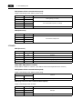
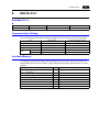
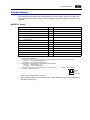
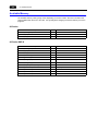
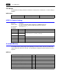
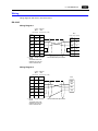
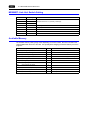
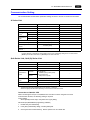
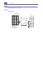
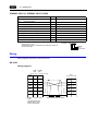
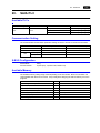
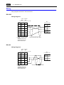
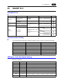
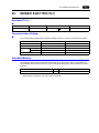
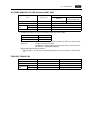
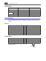
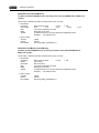
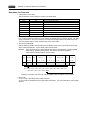
Available Memory
The available memory setting range varies depending on the PLC model. Be sure to set within the
range available with the PLC to be used. Use [TYPE] when assigning the indirect memory for macro
programs.
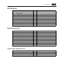
PLC-5 Series
Memory
TYPE
N
(integer)
0
B
(bit)
1
T.ACC
(timer/current value)
2
T.PRE
(timer/set value)
3
C.ACC
(counter/current value)
4
C.PRE
(counter/set value)
5
I
(input)
6
O
(output)
7
S
(status)
8
T
(timer/control)
9
C
(counter/control)
10
R
(control)
11
R.LEN
(control/data length)
12
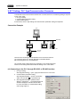
R.POS
(control/data position)
13
D
(BCD)
14
A
(ASCII)
15
Remarks
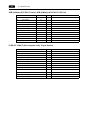
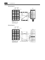
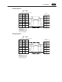
2. Allen-Bradley PLC
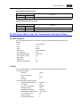
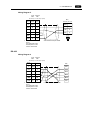
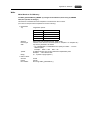
SLC500 Series, Micro Logix 1000
Memory
TYPE
N
(integer)
0
B
(bit)
1
T.ACC
(timer/current value)
2
T.PRE
(timer/set value)
3
C.ACC
(counter/current value)
4
C.PRE
(counter/set value)
5
I
(input)
6
O
(output)
7
S
(status)
8
T
(timer/control)
9
C
(counter/control)
10
R
(control)
11
R.LEN
(control/data length)
12
R.POS
(control/data position)
13
D
(BCD)
14
A
(ASCII)
15
F
(FLOAT)
16
ST
(STRING)
17
Remarks
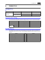
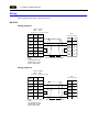
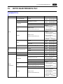
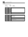
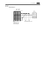
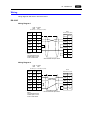
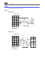
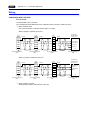
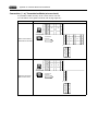
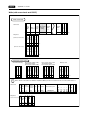
PLC-5 Series: Switch Setting
1785-KE
SW1 (Protocol)
No
Setting
1
ON
2
OFF
3
OFF
Contents
BCC, even, no
4
ON
5
OFF
Duplicated message unacceptable
Handshaking signal ignored
6
ON
Execution of diagnosis command
SW2 (Station number)
Set the station number of 1785-KE. (This station should not be duplicated in the network.)
No
Setting
1
ON
2
ON
3
ON/OFF
4
ON/OFF
5
ON/OFF
6
ON/OFF
7
ON/OFF
8
ON/OFF
Contents
1st digit (octal)
2nd digit (octal)
3rd digit (octal)
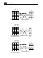
2-3
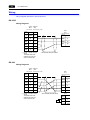
2-4
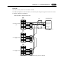
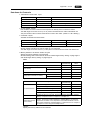
2. Allen-Bradley PLC
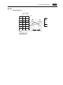
SW3 (Network link communication speed)
Adjust to the settings of the network you are using.
No
Setting
Contents
1
ON
2
ON
3
ON
4
ON
5
ON
6
ON
Local/remote selection
No
Setting
Contents
1
OFF
2
OFF
3
OFF
4
OFF
Data highway (57.6 kbps)
Link communication speed (19.2 kbps)
SW4 (Reserved)
For extension, always OFF
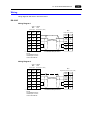
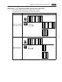
1770-KF2
SW1 (Protocol)
No
Setting
Contents
1
ON
Protocol
2
OFF
Protocol
3
ON
Duplicated message unacceptable
4
OFF
Handshaking signal ignored
5
OFF
Protocol
SW2, SW3, SW4 (Station number)
Set the station number of 1770-KF2. (This station should not be duplicated in the network.)
SW5 (Network link communication speed)
Adjust to the settings of the network you are using.
Switch Setting
1
2
ON
ON
Contents
57.6 kbps
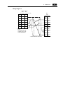
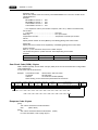
SW6 (Asynchronous link communication speed)
Adjust to the settings of the V7 series.
No
Setting
1
OFF
2
ON
3
ON
4
ON
Contents
9600 bps
Execution of diagnosis command
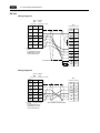
2. Allen-Bradley PLC
SW7 (Network link selection)
Switch Setting
1
2
ON
OFF
Contents
Peer transmission link
SW8 (RS-232C/RS-422 selection)
Switch Setting
1
Contents
2
OFF
ON
RS-232C
ON
OFF
RS-422
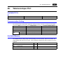
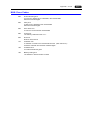
SLC500 Series, Micro Logix 100: Transmission Parameter Setting
CPU Port Channel 0
Set up the parameters for CPU port channel 0 using the software specifically designed for this
purpose.
Driver
: DF1 Full Duplex
Baud
: 19200
Parity
: EVEN
Control Line
: No Handshaking
Error Detection
: BCC
Embedded Responses
: Auto Detect
ACK Timeout (×20 ms)
: 20
NAK Retries
:3
ENQ Retries
:3
Duplicate Packet Detect
: ON
1747-KE
Set up the parameters for 1747-KE using the software specifically designed for this purpose.
DF1 Port Setup Menu
Baudrate
: 19200
Bits Per Character
:8
Parity
: Even
Stop Bits
:1
DF1 Full-Duplex Setup Parameters
Duplicate Packet Detection
: Enabled
Checksum
: BCC
Constant Carrier Detect
: Disabled
Message Timeout
: 400
Hardware Handshaking
: Disabled
Embedded Response Detect
: Auto Detect
ACK Timeout (×5 ms)
: 90
ENQuiry Retries
:3
NAK Received Retries
:3
2-5
2-6
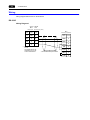
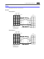
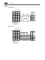
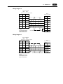
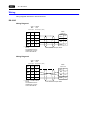
2. Allen-Bradley PLC
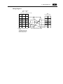
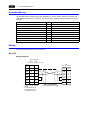
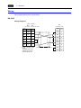
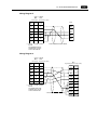
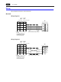
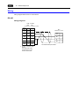
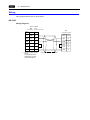
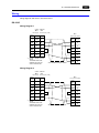
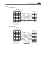
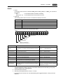
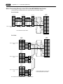
Wiring
Wiring diagrams with the PLC are shown below.
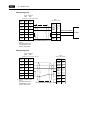
RS-232C
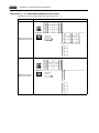
Wiring Diagram 1
V706 V Series
MJ2
CN1
RJ-45 8-pin
Signal
Name
D-sub 25-pin (male)
PLC
D-sub 15-pin (male)
Pin No. Pin No.
*1
SHELL
1
Signal
Name
Pin No.
SD
8
2
TXD
2
RD
7
3
RXD
3
RS
4
RTS
4
CS
5
CTS
5
7
DSR
6
SG
7
DCD
8
DTR
11
SG
13
SG
5
*1 Pin No. 1 of CN1 is used
as FG.
The metal shell of the
modular jack 2 on the
V706 is used as SG.
* Use shielded twist-pair cables.
Wiring Diagram 2
V706 V Series
MJ2
CN1
RJ-45 8-pin
D-sub 25-pin (male)
PLC
Signal
Name
Pin No.
Pin No.
*1
SHELL
1
Signal
Name
Pin No.
SD
8
2
TXD
2
RD
7
3
RXD
3
4
RTS
4
5
CTS
5
7
DSR
6
SG
7
DCD
8
DTR
20
RS
CS
SG
5
D-sub 25-pin (female)
*1 Pin No. 1 of CN1 is used
as FG.
The metal shell of the
modular jack 2 on the
V706 is used as SG.
* Use shielded twist-pair cables.
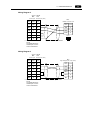
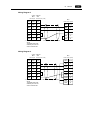
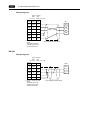
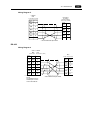
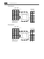
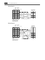
2. Allen-Bradley PLC
Wiring Diagram 3
V706 V Series
MJ2
CN1
PLC
RJ-45 8-pin D-sub 25-pin (male)
D-sub 9-pin (female)
Signal
Name
Pin No.
Pin No.
Signal
Name
Pin No.
*1
SHELL
1
DCD
1
SD
8
2
RXD
2
RD
7
3
TXD
3
RS
4
DTR
4
CS
5
COM
5
7
DSR
6
RTS
7
CTS
8
SG
5
*1 Pin No. 1 of CN1 is used
as FG.
The metal shell of the
modular jack 2 on the
V706 is used as SG.
* Use shielded twist-pair cables.
Wiring Diagram 4
V706 V Series
MJ2
CN1
RJ-45 8-pin
D-sub 25-pin (male)
PLC
Signal
Name
Pin No.
Pin No.
*1
SHELL
1
Signal
Name
Pin No.
SD
8
2
RXD
2
RD
7
3
TXD
3
RS
4
DTR
4
CS
5
COM
5
7
DSR
6
RTS
7
CTS
8
SG
5
*1 Pin No. 1 of CN1 is used
as FG.
The metal shell of the
modular jack 2 on the
V706 is used as SG.
D-sub 9-pin (female)
* Use shielded twist-pair cables.
2-7
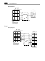
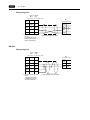
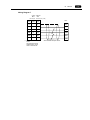
2-8
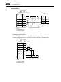
2. Allen-Bradley PLC
Wiring Diagram 5
V706 V Series
MJ2
CN1
RJ-45 8-pin
PLC
D-sub 9-pin (male)
D-sub 25-pin (male)
Signal
Name
Pin No.
Pin No.
Signal
Name
Pin No.
*1
SHELL
1
CD
1
SD
8
2
RD
2
RD
7
3
SD
3
RS
4
RS
4
CS
5
GND
5
7
DR
6
RS
7
CS
8
SG
5
*1 Pin No. 1 of CN1 is used
as FG.
The metal shell of the
modular jack 2 on the
V706 is used as SG.
* Use shielded twist-pair cables.
A•B’s RS-232C
Ladder transfer
cable
RS-422
Wiring Diagram 6
V706 V Series
MJ2
CN1
RJ-45 8-pin
D-sub 25-pin (male)
PLC
Signal
Name
Pin No.
Pin No.
*1
SHELL
1
Signal
Name
Pin No.
+SD
1
12
RTS
4
-SD
2
13
CTS
5
+RD
7
24
DSR
6
-RD
8
25
DCD
8
TDA
14
RDA
16
RDB
18
DTR
20
TDB
25
D-sub 25-pin (female)
*1 Pin No. 1 of CN1 is used
as FG.
The metal shell of the
modular jack 2 on the
V706 is used as SG.
* Use shielded twist-pair cables.
Micro
Logix
1000
2. Allen-Bradley PLC
Wiring Diagram 7
V706 V Series
MJ2
CN1
RJ-45 8-pin
D-sub 25-pin (male)
PLC
Signal
Name
Pin No.
Pin No.
*1
SHELL
1
Signal
Name
Pin No.
SG
5
7
TXD-
1
+SD
1
12
RXD-
2
-SD
2
13
COM
5
+RD
7
24
RXD+
6
-RD
8
25
TXD+
9
*1 Pin No. 1 of CN1 is used
as FG.
The metal shell of the
modular jack 2 on the
V706 is used as SG.
D-sub 9-pin (male)
* Use shielded twist-pair cables.
2-9
2-10
2. Allen-Bradley PLC
Please use this page freely.
3. Automationdirect PLC
3.
3-1
Automationdirect PLC
Available PLCs
Select PLC Type
PLC
Unit/Port
Connection
D4-430
D4-440
Direct LOGIC
D4-450
Port 1 on a CPU unit
RS-232C
RS-422
[Wiring Diagram 1]
[Wiring Diagram 5]
Port 3 on a CPU unit
RS-485
[Wiring Diagram 6]
RS-232C
[Wiring Diagram 2]
Port 2 on a CPU unit
D2-240
Port 2 on a CPU unit
D2-250
Port 2 on a CPU unit
RS-232C
[Wiring Diagram 3]
Port 1 on a CPU unit
RS-232C
RS-422
[Wiring Diagram 1]
[Wiring Diagram 5]
Port 0 on a CPU unit
RS-232C
[Wiring Diagram 4]
Port 3 on a CPU unit
RS-485
[Wiring Diagram 6]
RS-232C
[Wiring Diagram 2]
RS-232C
[Wiring Diagram 3]
D4-430
D4-440
D4-450
Direct LOGIC
(K-Sequence)
Port 2 on a CPU unit
D2-240
D2-250
Port 1 on a CPU unit
Port 2 on a CPU unit
Port 1 on a CPU unit
Port 2 on a CPU unit
Communication Setting
The recommended communication parameter settings of the PLC and the V7 series are as follows:
Item
Baud rate
Port
Parity
Setting on PLC
V7 Comm. Parameter Setting
19200 bps
19200 bps
“0” for ×10, “1” for ×1
1
Odd
Odd
Data length
8
8
Stop bit
1
1
Host link system (fixed)
−
0 (fixed)
−
Time-out
None (fixed)
−
ASCII/HEX
HEX (fixed)
−
Transmission
code
Function
Response delay time
3-2
3. Automationdirect PLC
Available Memory
The available memory setting range varies depending on the PLC model. Be sure to set within the
range available with the PLC to be used. Use [TYPE] when assigning the indirect memory for macro
programs.
Memory
V
TYPE
(data register)
0
X
(input relay)
1
Y
(output relay)
2
C
(internal relay)
3
S
(stage)
4
GX
(global inputs)
5
GY
(global outputs)
6
T
(timer/contact)
7
CT
(counter/contact)
8
Remarks
Wiring
Wiring diagrams with the PLC are shown below.
RS-232C
Wiring Diagram 1
V706 V Series
MJ2
CN1
RJ-45 8-pin
Signal
Name
D-sub 25-pin (male)
PLC
Pin No. Pin No.
D-sub 25-pin (male)
*1
SHELL
1
Signal
Name
Pin No.
SD
8
2
SD
2
RD
7
3
RD
3
RS
4
RS
4
CS
5
CS
5
7
SG
7
SG
5
*1 Pin No. 1 of CN1 is used
as FG.
The metal shell of the
modular jack 2 on the
V706 is used as SG.
* Use shielded twist-pair cables.
3. Automationdirect PLC
Wiring Diagram 2
V706 V Series
MJ2
CN1
RJ-45 8-pin
D-sub 25-pin (male)
PLC
Signal
Name
Pin No.
Pin No.
*1
SHELL
1
Signal
Name
Pin No.
SD
8
2
SG
1
RD
7
3
RxD
3
RS
4
TxD
4
CS
5
SG
5
Modular connector 6-pin
654321
7
*1 Pin No. 1 of CN1 is used
as FG.
The metal shell of the
modular jack 2 on the
V706 is used as SG.
* Use shielded twist-pair cables.
Wiring Diagram 3
V706 V Series
MJ2
CN1
RJ-45 8-pin
D-sub 25-pin (male)
PLC
Signal
Name
Pin No.
Pin No.
*1
SHELL
1
Signal
Name
Pin No.
SD
8
2
TXD
2
RD
7
3
RXD
3
RS
4
RTS
4
CS
5
CTS
5
0V
7
SG
5
High density D-sub 15-pin (male)
7
*1 Pin No. 1 of CN1 is used
as FG.
The metal shell of the
modular jack 2 on the
V706 is used as SG.
* Use shielded twist-pair cables.
3-3
3-4
3. Automationdirect PLC
Wiring Diagram 4
V706 V Series
MJ2
CN1
RJ-45 8-pin
Signal
Name
D-sub 25-pin (male)
PLC
Pin No. Pin No.
D-sub 15-pin (male)
*1
SHELL
1
Signal
Name
Pin No.
SD
8
2
TXD
2
RD
7
3
RXD
3
RS
4
0V
13
CS
5
SG
7
5
*1 Pin No. 1 of CN1 is used
as FG.
The metal shell of the
modular jack 2 on the
V706 is used as SG.
* Use shielded twist-pair cables.
RS-422
Wiring Diagram 5
V706 V Series
MJ2
CN1
RJ-45 8-pin
D-sub 25-pin (male)
PLC
Signal
Name
Pin No.
Pin No.
*1
SHELL
1
Signal
Name
Pin No.
SG
5
7
SG
7
+SD
1
12
RXD+
9
-SD
2
13
RXD−
10
+RD
7
24
CTS1+
11
-RD
8
25
TXD1+
14
TXD1−
16
RTS1+
18
RTS1−
19
CTS1+
23
D-sub 25-pin (male)
*1 Pin No. 1 of CN1 is used
as FG.
The metal shell of the
modular jack 2 on the
V706 is used as SG.
* Use shielded twist-pair cables.
3-5
3. Automationdirect PLC
Wiring Diagram 6
V706 V Series
MJ2
CN1
RJ-45 8-pin
D-sub 25-pin (male)
PLC
Signal
Name
Pin No.
Pin No.
*1
SHELL
1
Signal
Name
Pin No.
SG
5
7
SG
7
+SD
1
12
TXD3+
12
-SD
2
13
TXD3−
13
+RD
7
24
RXD3+
24
-RD
8
25
RXD3−
25
*1 Pin No. 1 of CN1 is used
as FG.
The metal shell of the
modular jack 2 on the
V706 is used as SG.
D-sub 25-pin (male)
* Use shielded twist-pair cables.
In case SU-6M, it is possible
to use terminal blocks.
3-6
3. Automationdirect PLC
Please use this page freely.
4. Baldor PLC
4.
4-1
Baldor PLC
Available PLCs
Select PLC Type
Unit/Port
Connection
NextMove (Comms Data Array)
Mint
Optimum (Comms Data Array)
RS-232C
[Wiring Diagram 1]
Communication Setting
The recommended communication parameter settings of the PLC and the V7 series are as follows:
Item
Baud rate
Port
Parity
Transmission
code
Setting on PLC
V7 Comm. Parameter Setting
9600 bps
9600 bps
0
0
None
None
Data length
8
8
Stop bit
1
1
Available Memory
The available memory setting range varies depending on the PLC model. Be sure to set within the
range available with the PLC to be used. Use [TYPE] when assigning the indirect memory for macro
programs.
Memory
I
TYPE
(Integer)
0
F
(Float)
1
B
(Integer omitting decimals)
2
Remarks
4-2
4. Baldor PLC
Wiring
Wiring diagram with the PLC is shown below.
RS-232C
Wiring Diagram 1
V706 V Series
MJ2
CN1
RJ-45 8-pin
Signal
Name
D-sub 25-pin (male)
PLC
Pin No. Pin No.
D-sub 9-pin (female)
*1
SHELL
1
Signal
Name
Pin No.
SD
8
2
RXD
2
RD
7
3
TXD
3
SG
5
7
DTR
4
SG
5
DSR
6
RTS
7
CTS
8
*1 Pin No. 1 of CN1 is used
as FG.
The metal shell of the
modular jack 2 on the
V706 is used as SG.
* Use shielded twist-pair cables.
5. DELTA PLC
5.
5-1
DELTA PLC
Available PLCs
Select PLC Type
PLC
DVP series
DVP series
Unit/Port
RS-485 Communication port
Connection
RS-485
[Wiring Diagram 1]
Communication Setting
The recommended communication parameter settings of the PLC and the V7 series are as follows:
Item
Baud rate
Port
Parity
Transmission
code
Setting on PLC
V7 Comm. Parameter Setting
9600 bps
9600 bps
1
1
Even
Even
Data length
7
7
Stop bit
1
1
Available Memory
The available memory setting range varies depending on the PLC model. Be sure to set within the
range available with the PLC to be used. Use [TYPE] when assigning the indirect memory for macro
programs.
Memory
D
TYPE
(data register)
0
X
(input relay)
1
Y
(output relay)
2
M
(auxiliary relay)
3
S
4
T
(timer)
5
C
(counter)
6
32C
(high-speed counter)
7
Remarks
5-2
5. DELTA PLC
Wiring
Wiring diagram with the PLC is shown below.
RS-485
Wiring Diagram 1
V706 V Series
MJ2
CN1
RJ-45 8-pin
Signal
Name
D-sub 25-pin (male)
Pin No. Pin No.
*1
SHELL
1
SG
5
7
PLC
+SD
1
12
+
-SD
2
13
-
+RD
7
24
-RD
8
25
* Use shielded twist-pair cables.
*1 Pin No. 1 of CN1 is used
as FG.
The metal shell of the
modular jack 2 on the
V706 is used as SG.
6. FANUC PLC
6.
6-1
FANUC PLC
Available PLCs
Select PLC Type
PLC
Power Mate-Model H/D
Power Mate
Unit/Port
Connection
Port on the CPU unit (JD14)
RS-422
[Wiring Diagram 2]
JD42
RS-232C
[Wiring Diagram 1]
JD40
RS-422
[Wiring Diagram 3]
Power Mate i Model H/D
Communication Setting
The recommended communication parameter settings of the PLC and the V7 series are as follows:
Item
Baud rate
Port
V7 Comm. Parameter Setting
−
0 (fixed)
−
Even (fixed)
−
Data length
8 (fixed)
−
Stop bit
1 (fixed)
−
Parity
Transmission
code
Setting on PLC
19200 bps (fixed)
Available Memory
The available memory setting range varies depending on the PLC model. Be sure to set within the
range available with the PLC to be used. Use [TYPE] when assigning the indirect memory for macro
programs.
Memory
D
TYPE
Remarks
(data table)
0
X
(input relay)
1
WX as word device
Y
(output relay)
2
WY as word device
R
(internal relay)
3
WR as word device
K
(keep relay)
4
WK as word device
T
(timer)
5
C
(counter)
6
6-2
6. FANUC PLC
Wiring
Wiring diagrams with the PLC are shown below.
RS-232C
Wiring Diagram 1
V706 V Series
MJ2
CN1
RJ-45 8-pin
D-sub 25-pin (male)
PLC
Signal
Name
Pin No.
Pin No.
*1
SHELL
1
Signal
Name
Pin No.
SD
8
2
RDB
9
RD
7
3
SDB
17
RS
4
0V
18
CS
5
SG
5
JD42
Half-pitch 20-pin
7
*1 Pin No. 1 of CN1 is used
as FG.
The metal shell of the
modular jack 2 on the
V706 is used as SG.
* Use shielded twist-pair cables.
RS-422
Wiring Diagram 2
V706 V Series
MJ2
CN1
RJ-45 8-pin
D-sub 25-pin (male)
PLC
JD14
Half-pitch 20-pin
Signal
Name
Pin No.
Pin No.
*1
SHELL
1
Signal
Name
Pin No.
SG
5
7
RDB
1
+SD
1
12
RDA
2
-SD
2
13
SDB
3
+RD
7
24
SDA
4
-RD
8
25
0V
11
*1 Pin No. 1 of CN1 is used
as FG.
The metal shell of the
modular jack 2 on the
V706 is used as SG.
* Use shielded twist-pair cables.
JD15
Signal
Name
Pin No.
RDB
1
RDA
2
R
R: 120 Ω 1/2W
6. FANUC PLC
Wiring Diagram 3
V706 V Series
MJ2
CN1
RJ-45 8-pin
D-sub 25-pin (male)
PLC
JD40
Half-pitch 20-pin
Signal
Name
Pin No.
Pin No.
*1
SHELL
1
Signal
Name
Pin No.
SG
5
7
RXD
1
+SD
1
12
*RXD
2
-SD
2
13
TXD
3
+RD
7
24
*TXD
4
-RD
8
25
RTS
5
*RTS
6
CTS
7
*CTS
8
0V
12
*1 Pin No. 1 of CN1 is used
as FG.
The metal shell of the
modular jack 2 on the
V706 is used as SG.
* Use shielded twist-pair cables.
6-3
6-4
6. FANUC PLC
Please use this page freely.
7. FATEK AUTOMATION PLC
7.
7-1
FATEK AUTOMATION PLC
Available PLCs
Select PLC Type
PLC
Unit/Port
Connection
RS-232
FACON FB series
FACON FB series
FB-DTBR
RS-422
[Wiring Diagram 1]
[Wiring Diagram 2]
[Wiring Diagram 3]
Communication Setting
The recommended communication parameter settings of the PLC and the V7 series are as follows:
Item
Setting on PLC
V7 Comm. Parameter Setting
9600 bps
9600 bps
Even (fixed)
−
Data length
7 (fixed)
−
Stop bit
1 (fixed)
−
Baud rate
Parity
Transmission
code
Available Memory
The available memory setting range varies depending on the PLC model. Be sure to set within the
range available with the PLC to be used. Use [TYPE] when assigning the indirect memory for macro
programs.
Memory
TYPE
Remarks
HR
(data register)
0
DR
(data register)
1
X
(input relay)
2
Y
(output relay)
3
M
(internal relay)
4
S
(step relay)
5
T
(timer contact)
6
Read only
C
(counter contact)
7
Read only
RT
(timer/current value)
8
RC
(counter/current value)
9
DRC
(32-bit counter/current value)
10
7-2
7. FATEK AUTOMATION PLC
Wiring
Wiring diagrams with the PLC are shown below.
RS-232C
Wiring Diagram 1
V706 V Series
MJ2
CN1
RJ-45 8-pin
D-sub 25-pin (male)
PLC
Signal
Name
Pin No.
Pin No.
*1
SHELL
1
Signal
Name
Pin No.
SD
8
2
RXD1
1
RD
7
3
TXD1
2
RS
4
RTS1
3
CS
5
CTS1
4
7
SG
6
SG
5
*1 Pin No. 1 of CN1 is used
as FG.
The metal shell of the
modular jack 2 on the
V706 is used as SG.
D-sub 15-pin (male)
* Use shielded twist-pair cables.
Wiring Diagram 2
V706 V Series
MJ2
CN1
RJ-45 8-pin
D-sub 25-pin (male)
PLC
Signal
Name
Pin No.
Pin No.
*1
SHELL
1
Signal
Name
Pin No.
SD
8
2
RXD1
2
RD
7
3
TXD1
3
RS
4
RTS1
4
CS
5
CTS1
5
SG
7
SG
5
D-sub 9-pin (male)
7
*1 Pin No. 1 of CN1 is used
as FG.
The metal shell of the
modular jack 2 on the
V706 is used as SG.
* Use shielded twist-pair cables.
7. FATEK AUTOMATION PLC
RS-422
Wiring Diagram 3
V706 V Series
MJ2
CN1
RJ-45 8-pin
Signal
Name
Pin No.
D-sub 25-pin (male)
Pin No.
PLC
*1
SHELL
1
Signal
Name
SG
5
7
D+
+SD
1
12
D-
-SD
2
13
SG
+RD
7
24
-RD
8
25
*1 Pin No. 1 of CN1 is used
as FG.
The metal shell of the
modular jack 2 on the
V706 is used as SG.
* Use shielded twist-pair cables.
7-3
7-4
7. FATEK AUTOMATION PLC
Please use this page freely.
8-1
8. Fuji Electric PLC
8.
Fuji Electric PLC
Available PLCs
Select PLC Type
PLC
F55
MICREX-F series
(MICREX-F series
V4)
Connection
PLC2Way
RS-232C [Wiring Diagram 1]
NC1L-RS2
RS-232C [Wiring Diagram 1]
NC1L-RS4
RS-485
F80H, F120H, F120S
F140S, F15 S
FFU120B
RS-232C [Wiring Diagram 1]
FFK120A
RS-485
NS-T
NJRS-1
RS-232C [Wiring Diagram 1]
NJRS-2
RS-232C [Wiring Diagram 1]
F70, F70S
SPB (N Mode) &
FLEX-PC series*1
[Wiring Diagram 3]
[Wiring Diagram 3]
NJ-T
SPB (N Mode) &
FLEX-PC CPU*2
FLEX-PC COM(T)
*1
*2
*3
Unit/Port
NV1L-RS2
NJRS-4
RS-485
FLEX-PC
CPU port
RS-485
Hakko Electronics’ cable
“FU-CPUNS”*3
NJ-B16
RS-232C port
RS-232C [Wiring Diagram 2]
FLEX-PC NJ-JM
Computer link terminal block
RS-422
[Wiring Diagram 3]
[Wiring Diagram 4]
To use FLEX-PC of Toyota version, select [FLEX-PC (T)].
To use FLEX-PC CPU of Toyota version, select [FLEX-PC CPU (T)].
For connection to MJ2 of a V706, use an MJ2-PLC adaptor plus FU-CPUNS.
Communication Setting
The recommended communication parameter settings of the PLC and the V7 series are as follows:
MICREX-F Series, SPB (N Mode) & FLEX-PC Series
Item
Baud rate
Port
Parity
Transmission
mode
Transmission
code
Setting on PLC
V7 Comm. Parameter Setting
19200 bps
19200 bps
0
0
Even
Even
RS-232C
1 (asynchronous non-protocol by
command) (fixed)
−
RS-422
3 (asynchronous non-protocol by
command) (fixed)
−
Data length
Stop bit
Terminating resistance at
receiver
7 (ASCII)
7
1
1
Provided for RS-485
−
SPB (N Mode) & FLEX-PC CPU Port
Connect to the CPU port. Communication parameters for the V7 series are automatically set.
8-2
8. Fuji Electric PLC
FLEX-PC COM (T) (NJ Computer Link) Toyota Version
Item
Setting on PLC
V7 Comm. Parameter Setting
19200 bps
19200 bps
0
0
Even
Even
Baud rate
Port
Parity
Transmission
code
Data length
7
7
Stop bit
2
2
MICREX-F Series, SPB (N Mode) & FLEX-PC Series: Switch Setting
MODE switch:
RS-232C: 1 RS-485: 3
RS-485 Port Setting SW:
“0” for both ×10, ×1
RS-485 terminating resistance: ON
Character switches
No
Setting
Contents
8
ON
7
ON
With parity
6
ON
Even
Switch Setting
5
ON
7 bits
4
ON
1 bit
3
ON
2
ON
1
OFF
Same as that set on V7 (normally 19200 bps)
8. Fuji Electric PLC
8-3
Available Memory
The available memory setting range varies depending on the PLC model. Be sure to set within the
range available with the PLC to be used. Use [TYPE] when assigning the indirect memory for macro
programs.
MICREX-F Series
Memory
TYPE
Remarks
M
(auxiliary relay)
0
WM as word device
K
(keep relay)
1
WK as word device
B
(input/output relay)
2
WB as word device
L
(link relay)
9
WL as word device
F
(special relay)
10
WF as word device
TS
(timer/set value)
11
*1
TR
(timer/current value)
12
*1
W9
(timer/current value 0.1)
13
*1
CS
(counter/set value)
14
*1
CR
(counter/current value)
15
*1
BD
(data memory)
16
*1
WS
(step control relay)
17
*2
(file memory)
18
*3
Wn
*1
*2
*3
For numerical data format where double-words can be used (Num. Data Display, Graph, Sampling), data is
processed as double-words.
For those where bits or words can be used, data is processed as words consisting of lower 16 bits.
For input:
Upper 16 bits are ignored.
For output: “0” is written for upper 16 bits.
Byte device such as step relay is processed as described below.
For input:
Upper 8 bits are “0.”
For output: Lower 8 bits are written.
To set up the file memory on the V-SFT editor, enter “file number” +
Example: W30 : 00002
“: (colon)” + “address” in order.
Address
Colon
File number
* Notes on V4 (or GD-80) data conversion
When converting data of V4 (or GD-80) into the V7 data, [MICREX-F series V4] is automatically
selected for the PLC type.
8-4
8. Fuji Electric PLC
SPB (N Mode) & FLEX-PC Series, SPB (N Mode) & FLEX-PC CPU Port
Toyota Version
TYPE
D
Standard Memory
(data register)
D
0
W
(link register)
R
1
M
(internal relay)
M
2
WM as word device
L
(latch relay)
K
3
WL (WK) as word device
X
(input relay)
X
4
WX as word device
Y
(output relay)
Y
5
WY as word device
R
(file register)
W
6
TN
(timer/current value)
TN
7
CN
(counter/current value)
CN
8
T
(timer/contact)
T
9
C
10
Not provided
11
C
(counter/contact)
WS
(step relay)
Remarks
FLEX-PC COM (T) (NJ Computer Link) Toyota Version
Memory
TYPE
Remarks
D
(data register)
0
R
(link register)
1
M
(internal relay)
2
WM as word device
K
(latch relay)
3
WK as word device
X
(input relay)
4
WX as word device
Y
(output relay)
5
WY as word device
W
(file register)
6
TN
(timer/current value)
7
CN
(counter/current value)
8
T
(timer/contact)
9
C
(counter/contact)
10
Z
(special register)
12
V
(special relay)
13
WV as word device
8. Fuji Electric PLC
Wiring
Wiring diagrams with the PLC are shown below.
RS-232C
Wiring Diagram 1
V706 V Series
MJ2
CN1
RJ-45 8-pin
D-sub 25-pin (male)
PLC
Signal
Name
Pin No.
Pin No.
*1
SHELL
1
Signal
Name
Pin No.
SD
8
2
SD
2
RD
7
3
RD
3
RS
4
RS
4
CS
5
CS
5
7
DR
6
SG
7
CD
8
SG
5
*1 Pin No. 1 of CN1 is used
as FG.
The metal shell of the
modular jack 2 on the
V706 is used as SG.
D-sub 25-pin (male)
* Use shielded twist-pair cables.
Wiring Diagram 2
V706 V Series
MJ2
CN1
RJ-45 8-pin
D-sub 25-pin (male)
NJ-B16
Signal
Name
Pin No.
Pin No.
*1
SHELL
1
Signal
Name
Pin No.
SD
8
2
RD
2
RD
7
3
SD
3
RS
4
CTS
4
CS
5
RTS
5
7
SG
7
SG
5
*1 Pin No. 1 of CN1 is used
as FG.
The metal shell of the
modular jack 2 on the
V706 is used as SG.
D-sub 15-pin (male)
* Use shielded twist-pair cables.
8-5
8-6
8. Fuji Electric PLC
RS-485
Wiring Diagram 3
V706 V Series
MJ2
CN1
RJ-45 8-pin
Signal
Name
Pin No.
D-sub 25-pin (male)
Pin No.
PLC
*1
SHELL
1
Signal
Name
SG
5
7
SDA
+SD
1
12
SDB
-SD
2
13
RDA
+RD
7
24
RDB
-RD
8
25
SG
*1 Pin No. 1 of CN1 is used
as FG.
The metal shell of the
modular jack 2 on the
V706 is used as SG.
* Use shielded twist-pair cables.
RS-422
Wiring Diagram 4
V706 V Series
MJ2
CN1
RJ-45 8-pin
Signal
Name
Pin No.
D-sub 25-pin (male)
Pin No.
PLC
*1
SHELL
1
Signal
Name
SG
5
7
+
+SD
1
12
-
-SD
2
13
SG
+RD
7
24
-RD
8
25
*1 Pin No. 1 of CN1 is used
as FG.
The metal shell of the
modular jack 2 on the
V706 is used as SG.
* Use shielded twist-pair cables.
9. GE Fanuc PLC
9.
9-1
GE Fanuc PLC
Available PLCs
Select PLC Type
PLC
Unit/Port
Connection
90 series
Series 90-30
Programmable coprocessor (PCM)
RS-232C
RS-485
90 series (SNP-X)
Series 90 micro
Series 90-30
CPU port
RS-485
[Wiring Diagram 1]
[Wiring Diagram 2]
[Wiring Diagram 3]
Communication Setting
The recommended communication parameter settings of the PLC and the V7 series are as follows:
90 Series
Item
Baud rate
Port
Parity
Setting on PLC
V7 Comm. Parameter Setting
19200 bps
19200 bps
01 (“0” for ×10, “1” ×1)
0
Odd
Odd
Data length
8
8
Stop bit
1
1
Host link function (fixed)
−
0 (fixed)
−
Timeout
None (fixed)
−
ASCII/HEX
HEX (fixed)
−
Setting on PLC
V7 Comm. Parameter Setting
19200 bps
19200 bps
Odd
Odd
Transmission
code
Functions
Response delay time
90 Series SNP-X
Item
Baud rate
Parity
Transmission
code
Functions
Data length
8
8
Stop bit
1
1
SNP-X (fixed)
−
9-2
9. GE Fanuc PLC
Available Memory
The available memory setting range varies depending on the PLC model. Be sure to set within the
range available with the PLC to be used. Use [TYPE] when assigning the indirect memory for macro
programs.
90 Series
Memory
R
TYPE
(data register)
0
I
(input)
1
Q
(output)
2
Remarks
90 Series SNP-X
Memory
R
TYPE
(data register)
0
I
(input)
1
Q
(output)
2
M
(internal relay)
3
G
(global relay)
4
AI
(analog input)
5
AQ
(analog output)
6
T
(temporary memory relay)
7
S
(system status)
8
SA
(system status)
9
SB
(system status)
10
SC
(system status)
11
Remarks
Read only
9. GE Fanuc PLC
Wiring
Wiring diagrams with the PLC are shown below.
RS-232C
Wiring Diagram 1
V706 V Series
MJ2
CN1
RJ-45 8-pin
D-sub 25-pin (male)
PLC
Signal
Name
Pin No.
Pin No.
*1
SHELL
1
Signal
Name
Pin No.
SD
8
2
SD
2
RD
7
3
RD
3
RS
4
RS
4
CS
5
CS
5
7
GND
7
5
SG
*1 Pin No. 1 of CN1 is used
as FG.
The metal shell of the
modular jack 2 on the
V706 is used as SG.
D-sub 25-pin (male)
* Use shielded twist-pair cables.
RS-485
Wiring Diagram 2
V706 V Series
MJ2
CN1
RJ-45 8-pin
D-sub 25-pin (male)
PLC
Signal
Name
Pin No.
Pin No.
*1
SHELL
1
Signal
Name
Pin No.
SG
5
7
0V
7
+SD
1
12
SD(A)
9
-SD
2
13
RTS(A)
10
+RD
7
24
CTS(A)
11
-RD
8
25
RD(A)
13
SD(B)
21
RTS(B)
22
CTS(B)
23
RT
24
RD(B)
25
D-sub 25-pin (male)
*1 Pin No. 1 of CN1 is used
as FG.
The metal shell of the
modular jack 2 on the
V706 is used as SG.
120
* Use shielded twist-pair cables.
9-3
9-4
9. GE Fanuc PLC
Wiring Diagram 3
V706 V Series
MJ2
CN1
RJ-45 8-pin
D-sub 25-pin (male)
PLC
Signal
Name
Pin No.
Pin No.
*1
SHELL
1
Signal
Name
Pin No.
SG
5
7
RTS(A)
6
+SD
1
12
0V
7
-SD
2
13
CTS(B’)
8
+RD
7
24
RT
9
-RD
8
25
RD(A’)
10
RD(B’)
11
SD(A)
12
SD(B)
13
RTS(B)
14
CTS(A’)
15
D-sub 15-pin (male)
*1 Pin No. 1 of CN1 is used
as FG.
The metal shell of the
modular jack 2 on the
V706 is used as SG.
* Use shielded twist-pair cables.
10. Hitachi PLC
10.
10-1
Hitachi PLC
Available PLCs
Select PLC Type
HIDIC-H
PLC
Unit/Port
COMM-2H
[Wiring Diagram 1]
[Wiring Diagram 4]
Peripheral port 1 on the CPU module
RS-232C
[Wiring Diagram 1]
EH150
HITACHI’s EH-RS05 cable*1 +
RS-232C [Wiring Diagram 1]
On H-252C CPU module
PERIPHERAL 1
RS-232C
[Wiring Diagram 1]
PERIPHERAL 2
HITACHI’s CNCOM-05
cable*1 + RS-232C
[Wiring Diagram 1]
Interface on the CPU unit
RS-422
[Wiring Diagram 5]
RS-232C connector on the CPU unit
RS-232C
[Wiring Diagram 2]
LQE060
RS-232C
[Wiring Diagram 3]
RS-422
[Wiring Diagram 5]
HIDIC H series
S10 2α
HIDIC-S10/2α
Connection
RS-232C
RS-422
S10 mini
ABS*2
HIDIC-S10/ABS
*1
*2
When using the HITACHI’s EH-RS05 or CNCOM-05 cable, connect the cable shown in [Wiring Diagram 1] to
the D-sub 15-pin side for communications with the V7 series.
Specify the absolute memory address. For more information, refer to the instruction manual for the PLC.
Communication Setting
The recommended communication parameter settings of the PLC and the V7 series are as follows:
COMM-2H
Item
Baud rate
Port
Setting on PLC
V7 Comm. Parameter Setting
19200 bps
19200 bps
0 for both ST No ×10, ×1
0
Even
Even
MODE7
Protocol 2 with port
Protocol 2 with port
Parity
Transmission
mode
RS-232C
RS-422
MODE9
Transmission
code
Data length
7 (ASCII)
7
1
1
Provided (fixed)
−
Stop bit
Sumcheck
If the transmission mode is any type other than listed the above, set the mode as shown below.
Item
Transmission
mode
*1
Setting on PLC
V7 Comm. Parameter Setting
RS-232C
MODE1
MODE2
MODE9
Protocol 1 without port
Protocol 1 with port
Protocol 2 without port
RS-422
MODE2
Protocol 1 with port*1
Multi-link connection is not available.
10-2
10. Hitachi PLC
CPU Module
The peripheral port setting should be “transmission control protocol 1 without port.” No other setting is
available.
HIDIC-S10α
Item
Setting on PLC
V7 Comm. Parameter Setting
7
19200 bps
Baud rate
HIDIC-H: Switch Setting
Baud rate:
MODE switch:
ST No switch:
DIP switch
19200 bps
To connect to both RS-232C and RS-422, set MODE switch to 9.
RS-232C (protocol 2 without port)RS-422 (protocol 2 with port)
“0” for both ×10, ×1
Switch
Setting
1
OFF
Contents
2
OFF
3
ON
4
ON
5
ON
With parity
6
ON
Even
7
OFF
Stop bit 1
8
ON
With sumcheck
Bit length
Same as that set on V7 (normally 19200 bps)
Available Memory
The available memory setting range varies depending on the PLC model. Be sure to set within the
range available with the PLC to be used. Use [TYPE] when assigning the indirect memory for macro
programs.
HIDIC-H
Memory
TYPE
Remarks
WR
(internal word output)
0
X
(external bit input)
1
Y
(external bit output)
2
WY as word device
L
(bit CPU link area)
3
WL as word device
M
(bit data area)
4
WM as word device
TC
(timer counter/elapsed time)
5
R
(relay)
6
TD
(timer counter/contact)
7
WN
(network input/output)
8
WX as word device
10. Hitachi PLC
HIDIC-S10/2α
Memory
TYPE
Remarks
FW
(work register)
0
X
(input relay)
1
XW as word device
Y
(output relay)
2
YW as word device
R
(internal relay)
3
RW as word device
G
(global link)
4
GW as word device
K
(keep relay)
5
KW as word device
T
(on-delay timer contact)
6
TW as word device
U
(one-shot timer contact)
7
UW as word device
C
(up/down counter contact)
8
CW as word device
TS
(on-delay timer set value)
9
TC
(on-delay timer elapsed value)
10
US
(one-short timer set value)
11
UC
(one-shot timer elapsed value)
12
CS
(up/down counter set value)
13
CC
(up/down counter elapsed value)
14
DW
(data register)
15
E
(event register)
16
EW as word device
S
(system register)
17
SW as word device
J
(transfer register)
18
JW as word device
Q
(receive register)
19
QW as word device
M
(extensional internal register)
20
MW as word device
HIDIC-S10/ABS
Memory
TYPE
0E
0
06
1
18
2
19
3
1A
4
1B
5
1C
6
1D
7
Remarks
10-3
10-4
10. Hitachi PLC
Wiring
Wiring diagrams with the PLC are shown below.
RS-232C
Wiring Diagram 1
V Series
CN1
D-sub 25-pin (male)
PLC
Signal
Name
Pin No.
FG
1
Signal
Name
Pin No.
SD
2
SD
2
RD
3
RD
3
CS
5
RS
4
SG
7
CS
5
DR
7
PHL
8
SG
9
PV12
14
D-sub 15-pin (male)
* Use shielded twist-pair cables.
Wiring Diagram 2
V706 V Series
MJ2
CN1
RJ-45 8-pin
D-sub 25-pin (male)
PLC
Signal
Name
Pin No.
Pin No.
*1
SHELL
1
Signal
Name
Pin No.
SD
8
2
RD
2
RD
7
3
SD
3
RS
4
SG
5
CS
5
SG
5
D-sub 9-pin (female)
7
*1 Pin No. 1 of CN1 is used
as FG.
The metal shell of the
modular jack 2 on the
V706 is used as SG.
* Use shielded twist-pair cables.
10. Hitachi PLC
Wiring Diagram 3
V706 V Series
MJ2
CN1
RJ-45 8-pin
PLC
D-sub 25-pin (male)
D-sub 9-pin (female)
Signal
Name
Pin No.
Pin No.
Signal
Name
Pin No.
*1
SHELL
1
CD
1
SD
8
2
RD
2
RD
7
3
SD
3
RS
4
ER
4
CS
5
SG
5
7
DR
6
RS
7
CS
8
SG
5
*1 Pin No. 1 of CN1 is used
as FG.
The metal shell of the
modular jack 2 on the
V706 is used as SG.
* Use shielded twist-pair cables.
RS-422
Wiring Diagram 4
V706 V Series
MJ2
CN1
RJ-45 8-pin
D-sub 25-pin (male)
Signal
Name
Pin No.
Pin No.
PLC
*1
SHELL
1
Signal
Name
+SD
1
12
TxDP
-SD
2
13
TxDN
+RD
7
24
RxDP
-RD
8
25
RxDN
*1 Pin No. 1 of CN1 is used
as FG.
The metal shell of the
modular jack 2 on the
V706 is used as SG.
* Use shielded twist-pair cables.
10-5
10-6
10. Hitachi PLC
Wiring Diagram 5
When connecting to the S10xα series, add a resistor of 50 Ω (1/2 W) as shown below.
V706 V Series
MJ2
CN1
RJ-45 8-pin
D-sub 25-pin (male)
Signal
Name
Pin No.
Pin No.
PLC
*1
SHELL
1
Signal
Name
+SD
1
12
UTX H
-SD
2
13
UTX L
+RD
7
24
50
URX H
-RD
8
25
50
URX L
*1 Pin No. 1 of CN1 is used
as FG.
The metal shell of the
modular jack 2 on the
V706 is used as SG.
* Use shielded twist-pair cables.
11. IDEC PLC
11.
11-1
IDEC PLC
Available PLCs
Select PLC Type
PLC
Unit/Port
Connection
MICRO3
MICRO3
Loader port
RS-232C
IDEC cable “FC2A-KC1”
or
IDEC cable “FC2A-KC1” *
+ [Wiring Diagram 1]
MICRO Smart
MICRO Smart
Loader port
RS-232C
IDEC cable “FC2A-KC4C”
+ [Wiring Diagram 1]
* When using RS-232C cable “FC2A-KC2” made by IDEC, connect the cable shown in [Wiring Diagram 3] to the
D-sub 9-pin side of the FC2A-KC2 cable for communications with the V7 series.
Communication Setting
The recommended communication parameter settings of the PLC and the V7 series are as follows:
Item
Baud rate
Port
Parity
Transmission
code
Setting on PLC
V7 Comm. Parameter Setting
9600 bps
9600 bps
1
1
Even
Even
Data length
7
7
Stop bit
1
1
Available Memory
The available memory setting range varies depending on the PLC model. Be sure to set within the
range available with the PLC to be used. Use [TYPE] when assigning the indirect memory for macro
programs.
Memory
D
TYPE
(data register)
0
I
(input)
1
Q
(output)
2
M
(internal relay)
3
R
(shift register)
4
TS
(timer/set value)
5
TN
(timer/enumerated value)
6
T
(timer/contact)
7
CS
(counter/set value)
8
CN
(counter/enumerated value)
9
C
(counter/contact)
10
Remarks
Read only
Read only
11-2
11. IDEC PLC
Wiring
Wiring diagram with the PLC is shown below.
RS-232C
Wiring Diagram 1
V706 V Series
MJ2
CN1
RJ-45 8-pin
PLC
D-sub 25-pin (male)
D-sub 9-pin (male)
Signal
Name
Pin No.
Pin No.
Signal
Name
Pin No.
*1
SHELL
1
CD
1
SD
8
2
SD
2
RD
7
3
RD
3
RS
4
ER
4
CS
5
GND
5
7
DR
6
RS
7
CS
8
SG
5
*1 Pin No. 1 of CN1 is used
as FG.
The metal shell of the
modular jack 2 on the
V706 is used as SG.
* Use shielded twist-pair cables.
12. KEYENCE PLC
12.
12-1
KEYENCE PLC
Available PLCs
Select PLC Type
PLC
Unit/Port
KZ300
KZ350
KZ series link
KZ-L2
KZ-A500CPU
*2
[Wiring Diagram 2]
[Wiring Diagram 6]
CPU modular port
KZ-L10
Port 1
RS-232C
Port 2
RS-232C
RS-422
KZ/KV series CPU
KZ-10, 16, 24, 40, 80, 300, 350
KZ/KV series*3
KZ24/300CPU
KZ-24, 300*2
CPU modular port
KV10/24CPU
KV-10, 24*3
CPU modular port
KV-700CPU
KV-700
CPU modular port
*1
*2
*3
[Wiring Diagram 1]
RS-232C
[Wiring Diagram 3]
RS-422
KEYENCE’s cable “KZ-C20”
+
Hakko Electronics’ cable “MB-CPUQ”*1
KZ-A500
MITSUBISHI A series
link
Connection
Port 1
RS-232C
Port 2
RS-232C
RS-422
CPU modular port
[Wiring Diagram 4]
[Wiring Diagram 2]
[Wiring Diagram 6]
RS-232C
[Wiring Diagram 5]
or
KEYENCE’s cable “OP-26487”
+
KEYENCE’s connector “OP-26485”
RS-232C
[Wiring Diagram 5]
or
KEYENCE’s cable “OP-26487”
+
KEYENCE’s connector “OP-26485”
For connection to MJ2 of a V706, use an MJ2-PLC adaptor plus KZ-C20 and MB-CPUQ.
To connect KZ-24, 300 via RS-232C, select [KZ24/300CPU] for the PLC type on the V-SFT editor.
To connect KZ-10, 24 via RS-232C, select [KV10, 24CPU] for the PLC type on the V-SFT editor.
12-2
12. KEYENCE PLC
Communication Setting
The recommended communication parameter settings of the PLC and the V7 series are as follows:
KZ Series Link
Item
Port
Baud rate
Parity
Data length
Transmission
code
Stop bit
Terminating resistance
Operation mode
Setting on PLC
V7 Comm. Parameter Setting
0
0
19200 bps
19200 bps
Even
Even
7 (ASCII)
7
2
2
ON for RS-422
−
Link mode
−
Set the port with the port setting switch, the terminating resistance with terminator, and the baud
rate/data bit/parity/stop bit with SET B DIP switches.
KZ-A500 CPU (CPU Modular Port)
Item
Port
Baud rate
Parity
Transmission
code
V7 Comm. Parameter Setting
0
0
9600 bps
9600 bps*1
Odd
Odd
Data length
8
8
Stop bit
1
1
ON for RS-422
−
Terminating resistance
*1
Setting on PLC
For signal level RS-422, baud rate is fixed to 9600 bps.
MITSUBISHI A Series Link (Link Unit KZ-L10)
Item
Port
Baud rate
Parity
Setting on PLC
V7 Comm. Parameter Setting
0
0
19200 bps
19200 bps
Even
Even
Data length
7
7
Stop bit
1
1
Sumcheck
Provided (fixed)
−
Terminating resistance
ON for RS-422
−
Transmission
code
Communication type
Normal communication
−
Transmission mode
Protocol code 1
Trans. Mode 1
Set the port with the port setting switch, the terminating resistance with terminator, and the baud rate/
data bit/parity/stop bit with SET B DIP switches.
For more information, refer to the instruction manual for KZ-L10.
KZ/KV Series CPU
Communication parameters for the V7 series are automatically set.
12. KEYENCE PLC
12-3
KV-700 CPU
Item
Setting on PLC
V7 Comm. Parameter Setting
0
0
9600 bps
9600 bps
Even
−
Data length
8
−
Stop bit
1
−
Port
*1
Baud rate
Parity
Transmission
code
*1
Maximum baud rate available is 57600 bps. Select the appropriate baud rate depending on the used PLC and
environment.
KZ24/300 CPU
Item
Port
0
38400 bps
38400 bps*1
Even
−
Data length
8
−
Stop bit
1
−
Parity
*1
V7 Comm. Parameter Setting
0
Baud rate
Transmission
code
Setting on PLC
Maximum baud rate available is 38400 bps. If a higher baud rate is selected, communications are performed
at 9600 bps.
KV10/24 CPU
Item
Port
Baud rate
*1
V7 Comm. Parameter Setting
0
0
57600 bps
57600 bps*1
Even
−
Data length
8
−
Stop bit
1
−
Parity
Transmission
code
Setting on PLC
Maximum baud rate available is 57600 bps. If a higher baud rate is selected, communications are performed
at 9600 bps.
12-4
12. KEYENCE PLC
Available Memory
The available memory setting range varies depending on the PLC model. Be sure to set within the
range available with the PLC to be used. Use [TYPE] when assigning the indirect memory for macro
programs.
KZ Series Link
Memory
TYPE
DM
(data memory)
0
CH
(input/output relay)
1
Remarks
KZ-A500 CPU, MITSUBISHI A Series Link
Memory
D
TYPE
(data register)
0
W
(link register)
1
R
(file register)
2
TN
(timer/current value)
3
CN
(counter/current value)
4
M
(internal relay)
6
L
(latch relay)
7
B
(link relay)
8
X
(input relay)
9
Y
(output relay)
10
TS
(timer/contact)
11
TC
(timer/coil)
12
CS
(counter/contact)
13
CC
(counter/coil)
14
Remarks
KZ/KV Series CPU, KZ24/300 CPU, KV10/24 CPU, KV-700 CPU
Memory
TYPE
Remarks
DM
(data memory)
0
CH
(input/output relay)
1
TC
(timer/current value)
2
CC
(counter/current value)
3
TS
(timer/set value)
4
CS
(counter/set value)
5
T
(timer/contact)
6
C
(counter/contact)
7
TM
(temporary data memory)
8
CTH
(high-speed counter/current value)
9
KV700 only
CTC
(high-speed counter comparator/setting
value)
10
KV700 only
CT
(high-speed counter comparator/contact)
11
KV700 only
CR
(control relay)
12
KV700 only
CM
(control relay)
13
KV700 only
12. KEYENCE PLC
Wiring
Wiring diagrams with the PLC are shown below.
RS-232C
Wiring Diagram 1
V706 V Series
MJ2
CN1
RJ-45 8-pin
D-sub 25-pin (male)
PLC
Signal
Name
Pin No.
Pin No.
*1
SHELL
1
Signal
Name
Pin No.
SD
8
2
SD
2
RD
7
3
RD
3
RS
4
RS
4
CS
5
CS
5
7
SG
7
SG
5
*1 Pin No. 1 of CN1 is used
as FG.
The metal shell of the
modular jack 2 on the
V706 is used as SG.
D-sub 25-pin (male)
* Use shielded twist-pair cables.
Wiring Diagram 2
V706 V Series
MJ2
CN1
RJ-45 8-pin
Signal
Name
Pin No.
D-sub 25-pin (male)
Pin No.
PLC
*1
SHELL
1
Signal
Name
SD
8
2
SD
RD
7
3
RD
RS
4
SG
CS
5
SG
5
7
*1 Pin No. 1 of CN1 is used
as FG.
The metal shell of the
modular jack 2 on the
V706 is used as SG.
* Use shielded twist-pair cables.
12-5
12-6
12. KEYENCE PLC
Wiring Diagram 3
V706 V Series
MJ2
CN1
RJ-45 8-pin
PLC
D-sub 25-pin (male)
Modular Connector 6-pin
Signal
Name
Pin No.
Pin No.
Signal
Name
Pin No.
*1
SHELL
1
CS
1
SD
8
2
SD
3
RD
7
3
SG
4
RS
4
RD
5
CS
5
RS
6
SG
5
7
*1 Pin No. 1 of CN1 is used
as FG.
The metal shell of the
modular jack 2 on the
V706 is used as SG.
123456
* Use shielded twist-pair cables.
Wiring Diagram 4
V706 V Series
MJ2
CN1
RJ-45 8-pin
D-sub 25-pin (male)
PLC
Signal
Name
Pin No.
Pin No.
*1
SHELL
1
Signal
Name
Pin No.
SD
8
2
SD
2
RD
7
3
RD
3
RS
4
RS
4
CS
5
CS
5
7
DR
6
SG
7
CD
8
SG
5
*1 Pin No. 1 of CN1 is used
as FG.
The metal shell of the
modular jack 2 on the
V706 is used as SG.
D-sub 25-pin (male)
* Use shielded twist-pair cables.
12. KEYENCE PLC
Wiring Diagram 5
V706 V Series
MJ2
CN1
RJ-45 8-pin
D-sub 25-pin (male)
PLC
Signal
Name
Pin No.
Pin No.
*1
SHELL
1
Signal
Name
Pin No.
SD
8
2
RD
3
RD
7
3
SG
4
RS
4
SD
5
CS
5
5
SG
Modular jack, 6-pin
123456
7
*1 Pin No. 1 of CN1 is used
as FG.
The metal shell of the
modular jack 2 on the
V706 is used as SG.
* Use shielded twist-pair cables.
RS-422
Wiring Diagram 6
V706 V Series
MJ2
CN1
RJ-45 8-pin
Signal
Name
Pin No.
D-sub 25-pin (male)
Pin No.
PLC
*1
SHELL
1
Signal
Name
SG
5
7
SDB
+SD
1
12
SDA
-SD
2
13
RDB
+RD
7
24
RDA
-RD
8
25
SG
*1 Pin No. 1 of CN1 is used
as FG.
The metal shell of the
modular jack 2 on the
V706 is used as SG.
* Use shielded twist-pair cables.
12-7
12-8
12. KEYENCE PLC
Please use this page freely.
13. KOYO ELECTRONICS PLC
13.
13-1
KOYO ELECTRONICS PLC
Available PLCs
Select PLC Type
PLC
SU-5/5E/6B/5M/6M
SU-5E/6E
SU-5M/6M
SZ-4
Unit/Port
U01-DM
[Wiring Diagram 1]
[Wiring Diagram 3]
Universal port 1 on CPU
RS-232C
RS-422
[Wiring Diagram 1]
[Wiring Diagram 7]
Universal port 3 on CPU
RS-485
[Wiring Diagram 8]
Universal port 2 on CPU
*1
RS-232C
KOYO’s programmer
connecting cable S-30JG-E
+
KOYO’s conversion
connector cable S-15CNJ
PORT2 on CPU
(universal communication port)
PORT2 on CPU
(universal communication port)
*1
RS-232C
KOYO’s programmer
connecting cable S-30JG-E
+
KOYO’s conversion
connector cable S-15CNJ
+
KOYO’s conversion
connector
S-15HCNP1
G01-DM
RS-232C
RS-422
[Wiring Diagram 1]
[Wiring Diagram 4]
Port on CPU
RS-232C
RS-422
[Wiring Diagram 1]
[Wiring Diagram 4]
Universal communication port on the CPU
unit
RS-232C
RS-485
[Wiring Diagram 2]
[Wiring Diagram 6]
U01-DM
RS-232C
RS-422
[Wiring Diagram 1]
[Wiring Diagram 3]
G01-DM
RS-232C
RS-422
[Wiring Diagram 1]
[Wiring Diagram 4]
SU/SG
SZ-4M
SG-8
PZ3
SR-T
SR-6T (Toyota version)
SR-T (K Protocol)
SR-1T (Toyota version)
SU-5E/6B
Terminal block on the CPU unit
RS-422
[Wiring Diagram 5]
Universal port 1 on CPU
RS-232C
RS-485
[Wiring Diagram 1]
[Wiring Diagram 7]
Programmer port on CPU
*1
RS-232C
KOYO’s programmer
connecting cable S-30JG-E
Universal port 3 on CPU
RS-485
Universal port 2 on CPU
*1
RS-232C
KOYO’s programmer
connecting cable S-30JG-E
+
KOYO’s conversion
connector cable S-15CNJ
SU-5M/6M
PORT1 on CPU (programmer port)
SZ-4
SU/SG
(K-Sequence)
PORT2 on CPU
(universal communication port)
PORT1 on CPU (programmer port)
SZ-4M
*1
Connection
RS-232C
RS-422
PORT2 on CPU
(universal communication port)
[Wiring Diagram 8]
*1
RS-232C
KOYO’s programmer
connecting cable S-30JG-E
+
KOYO’s conversion
connector cable S-15CNJ
+
KOYO’s conversion
connector
S-15HCNP1
When connecting to MJ2 on the V706, use an MJ2-PLC adaptor plus the designated cables.
13-2
13. KOYO ELECTRONICS PLC
Communication Setting
The recommended communication parameter settings of the PLC and the V7 series are as follows:
Item
Baud rate
Port
Parity
Transmission
code
Data length
Stop bit
Functions
Setting on PLC
V7 Comm. Parameter Setting
19200 bps
19200 bps
[0] × 10, [1] × 1
1
Odd
Odd
8
8
1
1
Host link function (fixed)
−
0 (fixed)
−
Timeout
None (fixed)
−
ASCII/HEX
HEX (fixed)
−
Response delay time
Available Memory
The available memory setting range varies depending on the PLC model. Be sure to set within the
range available with the PLC to be used. Use [TYPE] when assigning the indirect memory for macro
programs.
SU/SG, SU/SG (K-Sequence)
Memory
R
TYPE
(data register)
0
I
(input relay)
1
Q
(output relay)
2
M
(internal relay)
3
S
(stage)
4
GI
(global input)
5
GQ
(global output)
6
T
(timer/contact)
7
C
(counter/contact)
8
Remarks
SR-T/SR-T (K Protocol)
Memory
D
TYPE
Remarks
(data register)
0
X
(input relay)
1
Common to X/Y
Y
(output relay)
2
Common to X/Y
M
(internal relay)
3
S
(stage)
4
K
(keep relay)
5
L
(link relay)
6
T
(timer/contact)
7
C
(counter/contact)
8
13. KOYO ELECTRONICS PLC
Switch Setting
U-01DM
On-line/Off-line switch: On-line
UNIT ADR switch:
“0” for ×10, “1” for ×1
SW4 DIP switch:
No
Setting
1
ON
2
ON
3
ON
Contents
Same as that set on V7
Normally 19200 bps
4
ON
With parity
5
OFF
Self-diagnosis
6
OFF
7
OFF
8
OFF
Response delay time
0 msec
SW5 DIP switch:
No
Setting
1
OFF
Master/slave control
Contents
2
OFF
Slave
3
OFF
Communication timeout
4
OFF
HEX mode
13-3
13-4
13. KOYO ELECTRONICS PLC
G-01DM
On-line/Off-line switch: On-line
Short plug 1:
open
Short plug 2:
RS-232C . . . . . ENABLE
RS-422 . . . . . . DISENABLE
SW1 DIP switch:
No
Setting
1
ON
Contents
2
OFF
3
OFF
4
OFF
5
OFF
6
OFF
7
OFF
8
OFF
1:N
9
OFF
Slave
Unit No. 1
SW2 DIP switch:
No
Setting
1
ON
2
ON
3
ON
Contents
Same as that set on V7
Normally 19200 bps
4
ON
With parity
5
OFF
Self-diagnosis
6
OFF
Turn-around delay
7
OFF
8
OFF
9
OFF
Response delay time 0 msec
HEX mode
13. KOYO ELECTRONICS PLC
Wiring
Wiring diagrams with the PLC are shown below.
RS-232C
Wiring Diagram 1
V706 V Series
MJ2
CN1
RJ-45 8-pin
D-sub 25-pin (male)
PLC
Signal
Name
Pin No.
Pin No.
*1
SHELL
1
Signal
Name
Pin No.
SD
8
2
SD
2
RD
7
3
RD
3
RS
4
RS
4
CS
5
CS
5
7
SG
7
SG
5
*1 Pin No. 1 of CN1 is used
as FG.
The metal shell of the
modular jack 2 on the
V706 is used as SG.
D-sub 25-pin (male)
* Use shielded twist-pair cables.
Wiring Diagram 2
V706 V Series
MJ2
CN1
RJ-45 8-pin
D-sub 25-pin (male)
PLC
Signal
Name
Pin No.
Pin No.
*1
SHELL
1
Signal
Name
Pin No.
SD
8
2
TXD
2
RD
7
3
RXD
3
RS
4
RTS
4
CS
5
CTS
5
7
0V
7
SG
5
*1 Pin No. 1 of CN1 is used
as FG.
The metal shell of the
modular jack 2 on the
V706 is used as SG.
High-density D-sub 15-pin (male)
* Use shielded twist-pair cables.
13-5
13-6
13. KOYO ELECTRONICS PLC
RS-422
Wiring Diagram 3
V706 V Series
MJ2
CN1
RJ-45 8-pin
D-sub 25-pin (male)
PLC
Signal
Name
Pin No.
Pin No.
*1
SHELL
1
Signal
Name
Pin No.
SG
5
7
0V
7
+SD
1
12
+RTS
10
-SD
2
13
−RTS
11
+RD
7
24
+CTS
12
-RD
8
25
−CTS
13
+OUT
14
−OUT
15
−IN
16
+IN
17
−IN
24
+IN
25
D-sub 25-pin (male)
*1 Pin No. 1 of CN1 is used
as FG.
The metal shell of the
modular jack 2 on the
V706 is used as SG.
* Use shielded twist-pair cables.
150
Wiring Diagram 4
V706 V Series
MJ2
CN1
RJ-45 8-pin
D-sub 25-pin (male)
PLC
Signal
Name
Pin No.
Pin No.
*1
SHELL
1
Signal
Name
Pin No.
SG
5
7
0V
7
+SD
1
12
+OUT
14
-SD
2
13
−OUT
15
+RD
7
24
−IN
16
-RD
8
25
+IN
17
*1 Pin No. 1 of CN1 is used
as FG.
The metal shell of the
modular jack 2 on the
V706 is used as SG.
D-sub 25-pin (male)
* Use shielded twist-pair cables.
13. KOYO ELECTRONICS PLC
Wiring Diagram 5
V706 V Series
MJ2
CN1
RJ-45 8-pin
Signal
Name
Pin No.
D-sub 25-pin (male)
Pin No.
PLC
*1
SHELL
1
Signal
Name
SG
5
7
FG
+SD
1
12
T1
-SD
2
13
T2
+RD
7
24
T3
-RD
8
25
*1 Pin No. 1 of CN1 is used
as FG.
The metal shell of the
modular jack 2 on the
V706 is used as SG.
* Use shielded twist-pair cables.
Wiring Diagram 6
V706 V Series
MJ2
CN1
RJ-45 8-pin
D-sub 25-pin (male)
PLC
Signal
Name
Pin No.
Pin No.
*1
SHELL
1
Signal
Name
Pin No.
SG
5
7
RXD−
6
+SD
1
12
0V
7
-SD
2
13
TXD+
9
+RD
7
24
TXD−
10
-RD
8
25
RTS+
11
RTS−
12
RXD+
13
CTS+
14
CTS−
15
High-density D-sub 15-pin (male)
*1 Pin No. 1 of CN1 is used
as FG.
The metal shell of the
modular jack 2 on the
V706 is used as SG.
* Use shielded twist-pair cables.
13-7
13-8
13. KOYO ELECTRONICS PLC
Wiring Diagram 7
V706 V Series
MJ2
CN1
RJ-45 8-pin
D-sub 25-pin (male)
PLC
Signal
Name
Pin No.
Pin No.
*1
SHELL
1
Signal
Name
Pin No.
SG
5
7
SG
7
+SD
1
12
RXD+
9
-SD
2
13
RXD-
10
+RD
7
24
CTS1+
11
-RD
8
25
TXD1+
14
TXD1-
16
RTS1+
18
RTS1-
19
CTS1+
23
D-sub 25-pin (male)
*1 Pin No. 1 of CN1 is used
as FG.
The metal shell of the
modular jack 2 on the
V706 is used as SG.
* Use shielded twist-pair cables.
Wiring Diagram 8
V706 V Series
MJ2
CN1
RJ-45 8-pin
D-sub 25-pin (male)
PLC
Signal
Name
Pin No.
Pin No.
*1
SHELL
1
Signal
Name
Pin No.
SG
5
7
SG
7
+SD
1
12
TXD3+
12
-SD
2
13
TXD3-
13
+RD
7
24
RXD3+
24
-RD
8
25
RXD3-
25
*1 Pin No. 1 of CN1 is used
as FG.
The metal shell of the
modular jack 2 on the
V706 is used as SG.
D-sub 25-pin (male)
* Use shielded twist-pair cables.
SU-6M:
Terminal block connectable
14. LG PLC
14.
14-1
LG PLC
Available PLCs
Select PLC Type
PLC
Connection
MASTER-K10/60/200
K10/60/200
RS-232C
[Wiring Diagram 1]
MASTER-K500/1000
K500/1000
RS-232C
RS-422
[Wiring Diagram 2]
[Wiring Diagram 6]
MASTER-KxxxS
K200S/K300S/K1000S CPU port
RS-232C
[Wiring Diagram 3]
MASTER-KxxxS CNET
K4F-CUEA
GLOFA CNET
G4L-CUEA
RS-232C
RS-422
[Wiring Diagram 4]
[Wiring Diagram 7]
GLOFA GM series CPU
GM4/GM6/GM7 CPU port
RS-232C
[Wiring Diagram 5]
Communication Setting
The recommended communication parameter settings of the PLC and the V7 series are as follows:
MASTER-K10/60/200
Item
Baud rate
V7 Comm. Parameter Setting
−
None (fixed)
−
Data length
8 (fixed)
−
Stop bit
1 (fixed)
−
Parity
Transmission
code
Setting on PLC
9600 bps (fixed)
MASTER-K500/1000
Item
Setting on PLC
*1
V7 Comm. Parameter Setting
Baud rate
19200 bps
Parity
None (fixed)
−
Data length
8 (fixed)
−
Stop bit
1 (fixed)
−
Transmission
code
*1
19200 bps
For signal level RS-422, baud rate is fixed to 9600 bps.
MASTER-KxxxS
Item
Baud rate
V7 Comm. Parameter Setting
38400 bps
38400 bps
None (fixed)
−
Data length
8 (fixed)
−
Stop bit
1 (fixed)
−
Parity
Transmission
code
Setting on PLC
14-2
14. LG PLC
MASTER-KxxxS CNET / GLOFA CNET / GM Series CPU
Item
Setting on PLC
Baud rate
Parity
Transmission
code
V7 Comm. Parameter Setting
38400 bps
38400 bps
Not provided
Not provided
Data length
8
8
Stop bit
1
1
Available Memory
The available memory setting range varies depending on the PLC model. Be sure to set within the
range available with the PLC to be used. Use [TYPE] when assigning the indirect memory for macro
programs.
MASTER-K10/60/200
Memory
D
TYPE
(data register)
0
M
(auxiliary relay)
1
P
(input/output relay)
2
K
(keep relay)
3
TC
(timer/current value)
4
CC
(counter/current value)
5
TS
(timer/set value)
6
CS
(counter/set value)
7
Remarks
Input: Read only
MASTER-K500/1000
Memory
TYPE
P
(input/output relay)
0
M
(relay)
1
L
(link relay)
2
K
(keep relay)
3
F
(special relay)
4
T
(timer/current value)
5
C
(counter/set value)
6
D
(data register)
7
Remarks
Input: Read only
Read only
14. LG PLC
MASTER-KxxxS
Memory
TYPE
P
(input/output relay)
0
M
(auxiliary relay)
1
L
(link relay)
2
K
(keep relay)
3
F
(special relay)
4
T
(timer/current value)
5
C
(counter/set value)
6
D
(data register)
7
TC
(timer/contact)
9
CC
(counter/contact)
10
Remarks
Input: Read only
Read only
MASTER-KxxxS CNET
Memory
P
(input/output relay)
TYPE
0
Remarks
PW as word device, input: read only
M
(auxiliary relay)
1
MW as word device
L
(link relay)
2
LW as word device
K
(keep relay)
3
KW as word device
F
(special relay)
4
FW as word device, read only
T
(timer/current value)
5
C
(counter/setting value)
6
D
(data register)
7
TC
(timer/contact)
9
CC
(counter/contact)
10
GLOFA CNET / GM Series CPU
Memory
TYPE
Remarks
M
(internal memory)
0
MW as word device
Q
(output)
1
QW as word device
I
(input)
2
IW as word device
14-3
14-4
14. LG PLC
Wiring
Wiring diagrams with the PLC are shown below.
RS-232C
Wiring Diagram 1
V706 V Series
MJ2
CN1
RJ-45 8-pin
D-sub 25-pin (male)
PLC
Signal
Name
Pin No.
Pin No.
*1
SHELL
1
Signal
Name
Pin No.
SD
8
2
RXD
2
RD
7
3
TXD
3
SG
5
7
GND
5
*1 Pin No. 1 of CN1 is used
as FG.
The metal shell of the
modular jack 2 on the
V706 is used as SG.
D-sub 9-pin (male)
* Use shielded twist-pair cables.
Wiring Diagram 2
V706 V Series
MJ2
CN1
RJ-45 8-pin
D-sub 25-pin (male)
PLC
Signal
Name
Pin No.
Pin No.
*1
SHELL
1
Signal
Name
Pin No.
SD
8
2
TXD
2
RD
7
3
RXD
3
SG
5
7
GND
7
*1 Pin No. 1 of CN1 is used
as FG.
The metal shell of the
modular jack 2 on the
V706 is used as SG.
D-sub 25-pin (male)
* Use shielded twist-pair cables.
14. LG PLC
Wiring Diagram 3
V706 V Series
MJ2
CN1
RJ-45 8-pin
D-sub 25-pin (male)
PLC
Signal
Name
Pin No.
Pin No.
*1
SHELL
1
Signal
Name
Pin No.
SD
8
2
RXD
2
RD
7
3
TXD
3
RS
4
GND
5
CS
5
RTS
7
7
CTS
8
SG
5
*1 Pin No. 1 of CN1 is used
as FG.
The metal shell of the
modular jack 2 on the
V706 is used as SG.
D-sub 25-pin (male)
* Use shielded twist-pair cables.
Wiring Diagram 4
V706 V Series
MJ2
CN1
RJ-45 8-pin
Signal
Name
PLC
D-sub 25-pin (male)
Pin No. Pin No.
D-sub 25-pin (male)
Signal
Name
Pin No.
*1
SHELL
1
CD
1
SD
8
2
RXD
2
RD
7
3
TXD
3
RS
4
DTR
4
CS
5
GND
5
7
DSR
6
RTS
7
CTS
8
SG
5
*1 Pin No. 1 of CN1 is used
as FG.
The metal shell of the
modular jack 2 on the
V706 is used as SG.
* Use shielded twist-pair cables.
14-5
14-6
14. LG PLC
Wiring Diagram 5
V706 V Series
MJ2
CN1
RJ-45 8-pin
D-sub 25-pin (male)
PLC
Signal
Name
Pin No.
Pin No.
*1
SHELL
1
Signal
Name
Pin No.
SD
8
2
RXD
4
RD
7
3
SG
5
SG
5
7
TXD
7
*1 Pin No. 1 of CN1 is used
as FG.
The metal shell of the
modular jack 2 on the
V706 is used as SG.
D-sub 9-pin (male)
* Use shielded twist-pair cables.
RS-422
Wiring Diagram 6
V706 V Series
MJ2
CN1
RJ-45 8-pin
D-sub 25-pin (male)
PLC
Signal
Name
Pin No.
Pin No.
*1
SHELL
1
Signal
Name
Pin No.
+SD
1
12
SD+
10
-SD
2
13
SD-
11
+RD
7
24
-RD
8
25
*1 Pin No. 1 of CN1 is used
as FG.
The metal shell of the
modular jack 2 on the
V706 is used as SG.
D-sub 25-pin (male)
* Use shielded twist-pair cables.
14. LG PLC
Wiring Diagram 7
V706 V Series
MJ2
CN1
RJ-45 8-pin
Signal
Name
Pin No.
D-sub 25-pin (male)
Pin No.
PLC
*1
SHELL
1
Signal
Name
SG
5
7
SG
+SD
1
12
RDA
-SD
2
13
RDB
+RD
7
24
SDA
-RD
8
25
SDB
*1 Pin No. 1 of CN1 is used
as FG.
The metal shell of the
modular jack 2 on the
V706 is used as SG.
* Use shielded twist-pair cables.
14-7
14-8
14. LG PLC
Please use this page freely.
15. Matsushita Electric Works PLC
15.
15-1
Matsushita Electric Works PLC
Available PLCs
Select PLC Type
PLC
FP1
Unit/Port
Connection
PLC2Way
RS-232C port on the CPU unit
RS-232C [Wiring Diagram 1]
AFP3462
RS-232C [Wiring Diagram 1]
AFP3463
RS-422
AFP5462
RS-232C [Wiring Diagram 1]
FP3
FP5
[Wiring Diagram 4]
RS-232C tool port on the CPU unit
RS-232C [Wiring Diagram 1]
AFP5462
RS-232C [Wiring Diagram 1]
RS-232C port on the CPU unit
RS-232C [Wiring Diagram 1]
AFP3462
RS-232C [Wiring Diagram 1]
AFP3463
RS-422
RS-232C tool port on the CPU unit
MATSUSHITA’s RS-232C
cable
“AFC8513”*1
RS-232C port on the CPU unit
RS-232C [Wiring Diagram 3]
RS-232C port on the CPU unit
MATSUSHITA’s RS-232C
cable
“AFC8513”*1
RS-232C port on the CPU unit
RS-232C [Wiring Diagram 2]
FP10
MEWNET
FP10S
FP0
FP2
*1
[Wiring Diagram 4]
For connection to MJ2 of a V706, use an MJ2-PLC adaptor plus AFC8513.
Communication Setting
The recommended communication parameter settings of the PLC and the V7 series are as follows:
Item
Baud rate
Port
Parity
Transmission
code
V7 Comm. Parameter Setting
19200 bps
19200 bps
[0] × 10, [1] × 1
1
Even
Even
Data bit
7 (ASCII)
7
Stop bit
1
1
Computer link function (fixed)
−
Invalid (fixed)
−
Transmission mode
Control signal
Setting on PLC
* If a tool port (the ladder port for RS-232C) is used, the range of PLC parameter setting is limited as
below. Adjust the PLC parameter setting to communication parameter setting of the V7 series.
• Baud rate: 9600, 19200bps (maximum 115 kbps available with FP2)
• Parity:
Odd (fixed)
• Data bit:
8 or 7 (select “8” normally)
• Stop bit:
1 (fixed)
15-2
15. Matsushita Electric Works PLC
MEWNET: Link Unit Switch Setting
Switch
Setting
Contents
1
ON
2
OFF
3
OFF
4
OFF
Data length: 7 bits
5
ON
With parity
6
ON
Even
7
OFF
Stop bit 1
8
OFF
CS, CD invalid
Same as that set on V7 (normally 19200 bps)
Available Memory
The available memory setting range varies depending on the PLC model. Be sure to set within the
range available with the PLC to be used. Use [TYPE] when assigning the indirect memory for macro
programs.
Memory
DT
TYPE
Remarks
(data register)
0
X
(external input relay)
1
Y
(external output relay)
2
WY as word device
R
(internal relay)
3
WR as word device, including special relays
L
(link relay)
4
WL as word device
LD
(link register)
5
FL
(file register)
6
SV
(timer/counter set value)
7
EV
(timer/counter elapsed time)
8
T
(timer/contact)
9
Read only
C
(counter/contact)
10
Read only
WX as word device, read only
15. Matsushita Electric Works PLC
Wiring
Wiring diagrams with the PLC are shown below.
RS-232C
Wiring Diagram 1
V706 V Series
MJ2
CN1
RJ-45 8-pin
D-sub 25-pin (male)
PLC
Signal
Name
Pin No.
Pin No.
*1
SHELL
1
Signal
Name
Pin No.
SD
8
2
SD
2
RD
7
3
RD
3
RS
4
RS
4
CS
5
CS
5
7
SG
7
CD
8
ER
9
SG
5
*1 Pin No. 1 of CN1 is used
as FG.
The metal shell of the
modular jack 2 on the
V706 is used as SG.
D-sub 9-pin (male)
* Use shielded twist-pair cables.
Wiring Diagram 2
V706 V Series
MJ2
CN1
RJ-45 8-pin
D-sub 25-pin (male)
PLC
Signal
Name
Pin No.
Pin No.
*1
SHELL
1
Signal
Name
Pin No.
SD
8
2
SD
2
RD
7
3
RD
3
RS
4
RS
4
CS
5
CS
5
7
SG
7
SG
5
*1 Pin No. 1 of CN1 is used
as FG.
The metal shell of the
modular jack 2 on the
V706 is used as SG.
D-sub 9-pin (male)
* Use shielded twist-pair cables.
15-3
15-4
15. Matsushita Electric Works PLC
Wiring Diagram 3
V706 V Series
MJ2
CN1
RJ-45 8-pin
Signal
Name
Pin No.
D-sub 25-pin (male)
Pin No.
PLC
*1
SHELL
1
Signal
Name
SD
8
2
SD
RD
7
3
RD
RS
4
SG
CS
5
SG
5
7
*1 Pin No. 1 of CN1 is used
as FG.
The metal shell of the
modular jack 2 on the
V706 is used as SG.
* Use shielded twist-pair cables.
RS-422
Wiring Diagram 4
V706 V Series
MJ2
CN1
RJ-45 8-pin
D-sub 25-pin (male)
Signal
Name
Pin No.
Pin No.
PLC
*1
SHELL
1
Signal
Name
+SD
1
12
+
-SD
2
13
-
+RD
7
24
-RD
8
25
*1 Pin No. 1 of CN1 is used
as FG.
The metal shell of the
modular jack 2 on the
V706 is used as SG.
* Use shielded twist-pair cables.
16. MITSUBISHI ELECTRIC PLC
16.
16-1
MITSUBISHI ELECTRIC PLC
Available PLCs
A Series Link, QnA Series Link, QnH (Q) Series Link, A Link + Net10*1
Select PLC Type
CPU
Unit/Port
A2A, A3A
AJ71C24-S6
AJ71C24-S8
AJ71UC24
A2U, A3U, A4U
AJ71UC24
A1, A2, A3
A1N, A2N, A3N
A3H, A3M, A73
AJ71C24
AJ71C24-S3
AJ71C24-S6
AJ71C24-S8
AJ71UC24
A0J2, A0J2H
A2US
A1S, A1SJ, A2S
A2CCPUC24
PLC2Way
RS-232C [Wiring Diagram 2]
RS-422
[Wiring Diagram 5]
A0J2C214-S1
A1SJ71UC24-R2
A series link
Connection
RS-232C [Wiring Diagram 1]
A1SJ71UC24-R4
RS-422
A1SJ71UC24-PRF
RS-232C [Wiring Diagram 1]
[Wiring Diagram 5]
A1SJ71C24-R2
RS-232C [Wiring Diagram 1]
A1SJ71C24-R4
RS-422
A1SJ71C24-PRF
RS-232C [Wiring Diagram 1]
[Wiring Diagram 5]
CPU built-in link port
RS-232C [Wiring Diagram 1]
A1SJ71UC24-R2
RS-232C [Wiring Diagram 1]
A1SJ71UC24-R4
RS-422
QnH (A mode)
[Wiring Diagram 5]
RS-232C [Wiring Diagram 2]
AJ71QC24N
RS-422
[Wiring Diagram 5]
RS-232C [Wiring Diagram 2]
AJ71QC24
RS-422
Q2A, Q3A, Q4A
Q2ASx
QnA series link
[Wiring Diagram 5]
RS-232C [Wiring Diagram 1]
A1SJ71QC24
RS-422
[Wiring Diagram 5]
AJ71QC24-R4(CH1)
RS-422
[Wiring Diagram 6]
AJ71QC24-R4(CH2)
RS-422
[Wiring Diagram 5]
QnH (Q mode)
RS-232C [Wiring Diagram 1]
QJ71C24
Q00, Q01, Q00J
RS-422
Q00, Q01
RS-232C
Hakko Electronics’ cable
“QCPU2”*3
QnH (Q) series link
Tool port*2
[Wiring Diagram 5]
Standard type link +unit for A series link*1
A link + Net10
*1
*2
*3
For more information on A link + Net10, refer to page 16-13.
For notes on the connection between the tool port of a Q00/Q01 CPU and the V7 series using the serial
communication function, refer to page 16-3.
For the description of the ladder transfer function, refer to page 16-15.
For connection to MJ2 of a V706, use an MJ2-PLC adaptor plus QCPU2.
16-2
16. MITSUBISHI ELECTRIC PLC
A Series CPU, QnA Series CPU, QnH Series CPU, Q00J/00/01 CPU
Select PLC Type
CPU
A2A, A3A
A2U, A3U, A4U
A2US(H)
A1N, A2N, A3N
A3V, A73
A3H, A3M
A0J2H
A1S(H), A1SJ(H), A2S(H)
A2CCPUC24
A1FX
A series CPU
Unit/Port
Connection
PLC2Way
RS-422
Hakko Electronics’ cable
“MB-CPUQ”
or
[Wiring Diagram 7]
Tool port*1
Q2A, Q3A, Q4A
Q2AS(H)
QnA series CPU
QnH (A) series CPU
Q06H-A
Tool port
QnH (Q) series
CPU
Q02, Q02H
Q06H
Q12H
Q25H
Tool port*2
Q00J/00/01 CPU
Q00J
Q00
Q01
Tool port
RS-232C
Hakko Electronics’ cable
“QCPU2”*3
FX Series
Select PLC Type
FX series CPU
CPU
FX1/2
Unit/Port
Tool port*1
Tool port*1
RS-422
Hakko Electronics’ cable
“MI4-FX”*2
or
Hakko Electronics’ cable
“MB-CPUQ”
+
MITSUBISHI’s conversion
cable “FX-20P-CADP”
FX2N-232-BD
RS-232C [Wiring Diagram 3]
FX2N-485-BD
RS-485
[Wiring Diagram 8]
RS-422
Hakko Electronics’
cable “MI4-FX”*2
FX0N
FX2N series CPU
FX1S series CPU
FX2N/1N
FX2NC
FX1S
FX2N
FX2N-422-BD
FX1N
FX1S
FX series link
(A Protocol)
Connection
RS-232C
Hakko Electronics’ cable
“PC-CX24A”
RS-422
Hakko Electronics’ cable
“MB-CPUQ”
or
[Wiring Diagram 7]
FX1N-232-BD
RS-232C [Wiring Diagram 3]
FX1N-485-BD
RS-485
[Wiring Diagram 8]
RS-422
Hakko Electronics’
cable “MI4-FX”*2
FX1N-422-BD
FX0N-232ADP
RS-232C [Wiring Diagram 4]
FX0N-485ADP
RS-485
FX0N-232ADP
RS-232C [Wiring Diagram 4]
FX0N-485ADP
RS-485
PLC2Way
FX0N
[Wiring Diagram 8]
FX2NC
*1
*2
*3
[Wiring Diagram 8]
For more information of V-MDD (dual port interface), refer to page 16-15.
For the ladder transfer function used when directly connecting the QnH series CPU, refer to page 16-15.
For connection to MJ2 of a V706, use an MJ2-PLC adaptor plus QCPU2.
16. MITSUBISHI ELECTRIC PLC
16-3
Communication Setting
The recommended communication parameter settings of the PLC and the V7 series are as follows:
A Series Link
Item
Baud rate
Port
Setting on PLC
V7 Comm. Parameter Setting
19200 bps
19200 bps
0 for both stations ×10, ×1
0
Even
Even
Parity
Transmission
mode*1
RS-232C
MODE1
Trans. Mode 1
RS-422
MODE5
Trans. Mode 1
Transmission
code
Data length
7
7
Stop bit
1
1
Sumcheck
Provided (fixed)
−
Write while running
Possible (fixed)
−
Terminating resistance at
sender
Provided (fixed)
−
Terminating resistance at
receiver
Provided (fixed)
−
*1
Trans. Mode 1: without CR/LF, Trans. Mode 4: with CR/LF
If [Trans. Mode 4] is selected for [Trans. Mode] in the [Comm. Parameter] dialog of the V7 series, select
[MODE4] in the case of RS-232C, or [MODE8] in the case of RS-422.
QnA Series Link, QnH (Q) Series Link
Item
Baud rate*
Port
Parity
RS-232C
Transmission
mode
RS-422
Setting on PLC
V7 Comm. Parameter Setting
19200 bps
19200 bps
0 for both stations ×10, ×1
0
Even
Even
QnA series link:
MODE5 (binary mode) (fixed)
QnH (Q) series link:
MC protocol 5 (fixed)
−
8 (fixed)
−
1
1
Sumcheck
Provided (fixed)
−
Write while running
Possible (fixed)
−
Transmission
code
Data length
Stop bit
* The maximum baud rate available with the V7 series is 115200 bps.
Select the appropriate baud rate depending on the used PLC and environment.
Connection to Q00/Q01 CPU
When connecting the tool port of a Q00/Q01 CPU and the V7 series using the PLC serial
communication function, the following setting is required.
V-SFT Setting
Select [QnH(Q) series link] in the [Select PLC Type] dialog.
GX Developer (MITSUBISHI programming software)
1. Double-click [PLC Parameter].
2. In the [Qn(H) Parameter] dialog, click the [Serial] tab.
3. Check [Use serial communication]. Set the options such as a baud rate.
16-4
16. MITSUBISHI ELECTRIC PLC
Be sure to check these boxes.
Set the V7 communication parameters
as shown in this box.
A Series CPU, QnA Series CPU
Communication parameters for the V7 series are automatically set.
QnH (A) Series CPU, QnH (Q) Series CPU, Q00J/00/01 CPU
Communication parameters for the V7 series except the baud rate are automatically set.
* The maximum baud rate available with the V7 series is 115200 bps.
Select the appropriate baud rate depending on the used PLC and environment.
FX Series CPU, FX2N Series CPU, FX1S Series CPU
Communication parameters for the V7 series are automatically set.
FX Series Link (A Protocol)
Item
Baud rate
Parity
Transmission
code
Setting on PLC
V7 Comm. Parameter Setting
19200 bps
19200 bps
Even
Even
Data length
7
7
Stop bit
1
1
Special protocol communication (fixed)
−
H/W type*1
Normal/RS-232C
RS-232C
Sumcheck
Added (fixed)
−
Mode 1
Trans. Mode 1
Protocol
Transmission mode
*1
Select RS-485 when the link unit FX2N-485-BD, FX2N-422-BD, FX1N-485-BD, FX1N-422-BD or
FX0N-485-ADP is used.
* We recommend to set 2 ms or above for [Send Delay Time] in the [Detail] tab window of the
[Comm. Parameter] dialog of the V7 series.
16-5
16. MITSUBISHI ELECTRIC PLC
A Series Link, QnA Series Link: Switch Setting
The following is an example that shows the settings for both rotary DIP switches and DIP switches on
the PLC.
AJ71UC24
Example 1
Signal level: RS-232C, baud rate: 19200 bps, transmission mode 1
ON
STATION No
´10
STATION No
´1
MODE
B C D E
B C D E
B C D E
A
9
8
7
6
5 4 3
F
0
1
2
A
9
8
7
6
5 4 3
F
0
1
2
A
9
8
7
6
5 4 3
SW11
F
0
1
2
SW12
SW13
SW14
SW15
SW16
OFF
ON
SW17
SW18
SW21
SW22
SW23
SW24
A1SJ71C24-R2, A1SJ71UC24-R2
Example 2
Signal level: RS-232C, baud rate: 19200 bps, transmission mode 1
ON
STATION No
´10
STATION No
´1
MODE
B C D E
B C D E
B C D E
A
9
8
7
6
5 4 3
F
0
1
2
A
9
8
7
6
5 4 3
F
0
1
2
A
9
8
7
6
5 4 3
SW03
F
0
1
2
SW04
SW05
SW06
SW07
ON
SW08
OFF
SW09
SW10
SW11
SW12
AJ71QC24, A1SJ71QC24, AJ71QC24N
Example 3
Baud rate: 19200 bps
STATION No
´10
A
9
STATION No
´1
B C D E
F
0
1
8
7
6
5 4 3
2
A
9
F
0
1
8
7
6
5 4 3
2
ON
MODE
B C D E
A
9
B C D E
8
7
6
5 4 3
F
SW01
0
1
SW02
2
SW03
SW04
SW05
SW06
OFF
SW07
SW08
SW09
SW10
SW11
SW12
ON
16-6
16. MITSUBISHI ELECTRIC PLC
A1SJ71UC24-R4, A1SJ71C24-R4
Example 4
Signal level: RS-422, baud rate: 19200 bps, transmission mode 1
STATION No
´10
STATION No
´1
MODE
B C D E
B C D E
B C D E
A
9
8
7
6
5 4 3
A
9
F
0
1
2
8
7
6
5 4 3
F
0
1
2
A
9
8
7
6
5 4 3
ON
SW01
F
0
1
2
SW02
SW03
SW04
SW05
ON
SW06
OFF
SW07
SW08
SW09
SW10
SW11
SW12
Available Memory
The available memory setting range varies depending on the PLC model. Be sure to set within the
range available with the PLC to be used. Use [TYPE] when assigning the indirect memory for macro
programs.
A Series Link, QnA Series Link, QnH (Q) Series Link, A Series CPU, QnA Series CPU,
QnH (A) Series CPU, QnH (Q) Series CPU, Q00J/00/01 CPU, A Link + Net10
Memory
D
TYPE
(data register)
0
W
(link register)
1
R
(file register)
2
TN
(timer/current value)
3
CN
(counter/current value)
4
SPU
(special unit buffer memory)
5
M
(internal relay)
6
L
(latch relay)
7
B
(link relay)
8
X
(input relay)
9
Y
(output relay)
10
TS
(timer/contact)
11
TC
(timer/coil)
12
CS
(counter/contact)
13
CC
(counter/coil)
14
Remarks
*1
*2
H
(link unit buffer memory)
15
SD
(special register)
16
QnA, QnH (Q) series only (both link unit and CPU)
SM
(special relay)
17
QnA, QnH (Q) series only (both link unit and CPU)
SB
(special relay)
18
QnA, QnH (Q) series only (both link unit and CPU)
SW
(special link register)
19
QnA, QnH (Q) series only (both link unit and CPU)
ZR
(file register (for continuous access))
20
QnA, QnH (Q) series only (both link unit and CPU)
*1
*2
When the A series CPU is in ROM operation, R register cannot be used.
The unit number is required in addition to the memory type and address. Convert byte address into word
address when entering the data on the V-SFT editor if the memory device of link unit is given byte address.
16. MITSUBISHI ELECTRIC PLC
16-7
FX Series, FX1S Series
Memory
TYPE
D
(data register)
0
TN
(timer/current value)
1
CN
(counter/current value)
2
32CN
(counter 32 bits)
3
M
(internal relay)
4
S
(state)
5
X
(input relay)
6
Y
(output relay)
7
TS
(timer/contact)
8
CS
(counter/contact)
9
(file register)
10
DX
*1
*2
Remarks
*1
Read only
*2
For numerical data format where double-words can be used (Num. Data Display, Graph, Sampling), data is
processed as double-words.
For those where bits or words can be used, data is processed as words consisting of lower 16 bits.
For input
Upper 16 bits are ignored.
For output
“0” is written for upper 16 bits.
Use DX for D1000 to 2999.
FX2N Series
Memory
D
TYPE
(data register)
0
TN
(timer/current value)
1
CN
(counter/current value)
2
32CN
(counter 32 bits)
3
M
(internal relay)
4
S
(state)
5
X
(input relay)
6
Y
(output relay)
7
TS
(timer/contact)
8
CS
(counter/contact)
9
*1
Remarks
*1
Read only
For numerical data format where double-words can be used (Num. Data Display, Graph, Sampling), data is
processed as double-words.
For those where bits or words can be used, data is processed as words consisting of lower 16 bits.
For input
Upper 16 bits are ignored.
For output
“0” is written for upper 16 bits.
16-8
16. MITSUBISHI ELECTRIC PLC
FX Series (A Protocol)
Memory
TYPE
Remarks
D
(data register)
0
TN
(timer/current value)
1
CN
(counter/current value)
2
*1
32CN
(counter 32 bits)
3
*2
M
(internal relay)
4
S
(state)
5
X
(input relay)
6
Y
(output relay)
7
TS
(timer/contact)
8
CS
(counter/contact)
9
*1
*2
Read only
CN200 to CN255 equals 32CN (32-bit counter).
For numerical data format where double-words can be used (Num. Data Display, Graph, Sampling), data is
processed as double-words.
For those where bits or words can be used, data is processed as words consisting of lower 16 bits.
For input
Upper 16 bits are ignored.
For output
“0” is written for upper 16 bits.
Wiring
Wiring diagrams with the PLC are shown below.
RS-232C
Wiring Diagram 1
V706 V Series
MJ2
CN1
RJ-45 8-pin
D-sub 25-pin (male)
PLC
Signal
Name
Pin No.
Pin No.
*1
SHELL
1
Signal
Name
Pin No.
SD
8
2
CD
1
RD
7
3
RD
2
RS
4
SD
3
CS
5
SG
5
7
DR
6
RS
7
CS
8
SG
5
*1 Pin No. 1 of CN1 is used
as FG.
The metal shell of the
modular jack 2 on the
V706 is used as SG.
D-sub 9-pin (male)
* Use shielded twist-pair cables.
16. MITSUBISHI ELECTRIC PLC
Wiring Diagram 2
V706 V Series
MJ2
CN1
RJ-45 8-pin
D-sub 25-pin (male)
PLC
Signal
Name
Pin No.
Pin No.
*1
SHELL
1
Signal
Name
Pin No.
SD
8
2
SD
2
RD
7
3
RD
3
RS
4
RS
4
CS
5
CS
5
7
DR
6
SG
7
CD
8
SG
5
*1 Pin No. 1 of CN1 is used
as FG.
The metal shell of the
modular jack 2 on the
V706 is used as SG.
D-sub 25-pin (male)
* Use shielded twist-pair cables.
Wiring Diagram 3
V706 V Series
MJ2
CN1
RJ-45 8-pin
D-sub 25-pin (male)
PLC
Signal
Name
Pin No.
Pin No.
*1
SHELL
1
Signal
Name
Pin No.
SD
8
2
RD
2
RD
7
3
SD
3
RS
4
SG
5
CS
5
SG
5
D-sub 9-pin (female)
7
*1 Pin No. 1 of CN1 is used
as FG.
The metal shell of the
modular jack 2 on the
V706 is used as SG.
* Use shielded twist-pair cables.
16-9
16-10
16. MITSUBISHI ELECTRIC PLC
Wiring Diagram 4
V706 V Series
MJ2
CN1
RJ-45 8-pin
D-sub 25-pin (male)
PLC
Signal
Name
Pin No.
Pin No.
*1
SHELL
1
Signal
Name
Pin No.
SD
8
2
SD
2
RD
7
3
RD
3
RS
4
SG
7
CS
5
SG
5
D-sub 25-pin (male)
7
*1 Pin No. 1 of CN1 is used
as FG.
The metal shell of the
modular jack 2 on the
V706 is used as SG.
* Use shielded twist-pair cables.
RS-422
Wiring Diagram 5
V706 V Series
MJ2
CN1
RJ-45 8-pin
D-sub 25-pin (male)
Signal
Name
Pin No.
Pin No.
PLC
*1
SHELL
1
Signal
Name
SG
5
7
SDA
+SD
1
12
SDB
-SD
2
13
RDA
+RD
7
24
RDB
-RD
8
25
SG
*1 Pin No. 1 of CN1 is used
as FG.
The metal shell of the
modular jack 2 on the
V706 is used as SG.
* Use shielded twist-pair cables.
16. MITSUBISHI ELECTRIC PLC
Wiring Diagram 6
V706 V Series
MJ2
CN1
RJ-45 8-pin
Signal
Name
D-sub 25-pin (male)
Pin No. Pin No.
PLC
D-sub 25-pin (male)
*1
SHELL
1
Signal
Name
Pin No.
SG
5
7
RDA
2
+SD
1
12
SDA
3
-SD
2
13
DSRA
4
+RD
7
24
DTRA
5
-RD
8
25
SG
7
RDB
15
SDB
16
DSRB
17
DTRB
18
*1 Pin No. 1 of CN1 is used
as FG.
The metal shell of the
modular jack 2 on the
V706 is used as SG.
20
* Use shielded twist-pair cables.
21
Wiring Diagram 7
V Series
CN1
D-sub 25-pin (male)
PLC
Signal
Name
Pin No.
FG
1
Signal
Name
Pin No.
SG
7
2
+RxD
+SD
12
3
+TxD
-SD
13
4
+DSR
+RTS
14
5
+DTR
-RTS
17
7
SG
-CTS
18
15
-RxD
+CTS
19
16
-TxD
+RD
24
17
-DSR
-RD
25
18
-DTR
D-sub 25-pin (male)
20
21
* Use shielded twist-pair cables.
16-11
16-12
16. MITSUBISHI ELECTRIC PLC
According to our noise tests, the attachment of a ferrite core improves noise voltage by 650 to 900 V and aids in
preventing communication errors.
• When connecting to the A/QnA series CPU directly, attach a ferrite core to the communication cable between
the V7 series and A/QnA series CPU to avoid noise problems.
Ferrite core
A/QnA series
CPU
V7 series
• Ferrite cores are optionally available.
When ordering the ferrite core, state “GD-FC (ID: 8 mm, OD: 20 mm).”
• In consideration of such noise problems, it is recommended that the standard type link unit be used when the
cable length of 15 m or longer is required.
Wiring Diagram 8
V706 V Series
MJ2
CN1
RJ-45 8-pin
D-sub 25-pin (male)
Signal
Name
Pin No.
Pin No.
PLC
*1
SHELL
1
Signal
Name
SG
5
7
RDA
+SD
1
12
SDA
-SD
2
13
SG
+RD
7
24
RDB
-RD
8
25
SDB
*1 Pin No. 1 of CN1 is used
as FG.
The metal shell of the
modular jack 2 on the
V706 is used as SG.
* Use shielded twist-pair cables.
16. MITSUBISHI ELECTRIC PLC
16-13
A Link + Net10
• When the V7 series is connected to the standard type link unit on the CPU that is connected to the
data link system or network system, the V7 series can have access to CPUs on NET II (/B) and
NET/10. In this case, select “A Link + Net10” for [PLC Type] on the VSFT editor.
• When the V7 series has access to the CPU on NET II (/B) or NET/10:
- With NET II (/B), the V7 series can only have access to CPUs in the network (No. 1 in the
illustration below) of the CPU equipped with the standard type link unit that is connected to the
V7 series.
(Available CPU No. 0 to 30)
- With NET/10, the V7 series can have access to CPUs in the network (No. 1 in the illustration
below) of the CPU equipped with the standard type link unit that is connected to the V7 series
as well as those in the other networks (Nos. 2 and 3 in the illustration below) that are
connected. (Available CPU No. 1 to 30)
SYSTEM
F1
F2
F3
Standard type
link unit
F4
F5
F6
F7
POWER
V7
CPU
(1-1)
CPU
(2-1)
CPU
(1-5)
CPU
(2-5)
Network No. 1
CPU
(1-2)
(2-2)
Network No. 2
CPU
(1-4)
CPU
(2-4)
CPU
(2-3)
(3-1)
CPU
(1-3)
CPU
(2-4)
(3-2)
Network No. 3
CPU
(3-5)
CPU
(3-3)
CPU
(3-4)
• When the V7 series reads from or writes to the CPU (“1-1” in the above illustration) equipped with
the standard type link unit:
Set “31” for [CPU No.] for memory setting on the V-SFT editor.
The response time is the same as that with 1 : 1 connection between the V7 series and the PLC.
When the V7 series reads from or writes to the CPU memory of the CPU number other than “31”:
Transient transmission is performed and the response time is not fast. Please understand
beforehand.
• To have access to the PLC in the other network on NET/10, specify the network number in the
OPEN macro for the screen on the V-SFT editor.
This macro command should be [OUT_ENQ] of system call [SYS]. It is not possible to have
access to the CPU on the different network from the same screen.
16-14
16. MITSUBISHI ELECTRIC PLC
• Network specifying macro............... [OUT_ENQ] of system call [SYS]
F1 memory
n+0
Always 0
n+1
Network selection: 2
n+2
System code
n+3
Network number
“n + 0” and “n + 1” are fixed to “0” and “2”, respectively.
“n + 2” (system code) should be:
1: NET/10
2: NET II (/B)
For “n + 3” (network number), set “0” when NET II (/B) is selected for “n + 2” (system code) or
the network number to be accessed when NET/10 is selected.
Do not use this macro for any purpose other than OPEN macro for a screen. Doing so triggers
network switching at the time of macro execution, resulting in a communication error.
For more information on the macro function, refer to the Reference Manual (Function).
Also refer to the explanation on network registration contained in the operation manual for
MITSUBISHI’s Standard Link/Multi-drop Link Unit.
• For the NET II (/B) data link system and NET/10 network system, refer to MITSUBISHI’s manual.
Available Memory
For the available memory of the PLC to be accessed, refer to “Available Memory” (page 16-6).
Note that the CPU number must be set on the V-SFT editor.
Wiring
Refer to the wiring diagram with the standard type link unit.
16. MITSUBISHI ELECTRIC PLC
16-15
V-MDD (Dual Port Interface)
V-MDD is the add-on connector with two ports, specifically designed for the connector on
MITSUBISHI’s A series, QnA series or FX series CPU programming port.
MITSUBISHI A/QnA/FX series
CPU
A6GPP, A7PHP, computer, etc.
G
P
P
When connecting to the CPU of the MITSUBISHI A/QnA
series:
Insert the connector on the backside into the CPU port
directly or use the MDD-CPU (optional) cable for
connection.
When connecting to the CPU of the MITSUBISHI FX1/2 series:
Use the MDD-CPU cable (optional) for connection.
When connecting to the CPU of the MITSUBISHI
FX2N/1N/0N/1S series:
Use MITSUBISHI’s conversion cable “FX-20P-CADP.”
123
GD
Slide switch
1: A series
2: QnA series
3: FX series
MB-CPUQ cable (optional)
SYSTEM
F1
*
Set the slide switch before turning
the power on.
F2
F3
F4
F5
F6
F7
POWER
V7
* V-MDD cannot be used with the MI4-FX cable.
• The power to the V-MDD is supplied from the CPU. Check the electric capacity of 5 V at the CPU.
(Current consumption: Max. 350 mA)
• Keep the cable between the CPU and V-MDD as short as possible. (Max. 1 to 1.5 m)
• Be sure to consider noise problems when performing wiring.
• When V-MDD is used for connection with the V7 series, set 1.5 seconds or above for the timeout
time in the [Comm. Parameter] dialog.
• Please read the instruction manual for V-MDD before use.
Ladder Transfer Function
Up until now it has been necessary to debug the data by repeatedly disconnecting and reconnecting
the two computer-PLC and V7-PLC cables when the V7 series is directly connected to a PLC
equipped with only one CPU port. With the ladder transfer function, however, it is possible to write
ladder programs or monitor the PLC memory using the V7 series without disconnecting and
reconnecting the cables.
Applicable Models
Select PLC Type
QnH (Q) series CPU
CPU
Ladder Communication Program
Q02(H), 06H
MelQHCpQ.lcm
QnH (Q) series link
Q00, Q01
MelQnA.lcm
FX series CPU
FX1/2, FX0N
FX2N series CPU
FX2N/1N, FX2NC
FX1S series CPU
FX1S
MelFx.lcm
* 1 : n communication (multi-drop), multi-link communication, and multi-link 2 communication cannot
be executed.
16-16
16. MITSUBISHI ELECTRIC PLC
Connection
• When connecting the V7 series (CN1) to the PLC (CPU port), use a 1 : 1 communication cable as
previously described.
• Use Hakko Electronics’ V6-CP cable when connecting the computer (PLC programming software)
and the V7 series (MJ1/2).
1 : 1 communication cable
V6-CP
disc
GPPW
(V-SFT)
RESET
MJ1/2
COM
SYSTEM
F1
CN1
CPU port
MELSEC
F2
V7
F3
F4
F5
F6
F7
POWER
V7 series
Computer (PC)
MITSUBISHI QnH/FX series
Communications between the computer and the PLC
Communications between V7 and the PLC
• When using the V-SFT editor and the PLC programming software:
- When using two V6-CP cables:
When the computer has two COM ports, use one port for the V-SFT editor and the other port
for the PLC programming software. Use the V6-CP cables. (It is not possible to transfer the
V-SFT editor and the PLC programming software at the same time.)
Communications between the PLC programming software and the PLC
Communications between the V-SFT editor and V7
Communications between V7 and the PLC
1 : 1 communication cable
V6-CP
MJ1
COM1
disc
RESET
GPPW
(V-SFT)
SYSTEM
CN1
CPU port
MELSEC
F1
F2
V7
F3
F4
F5
F6
F7
POWER
Computer (PC)
MJ2
COM2
V6-CP
V7 series
MITSUBISHI QnH/FX series
- When using one V6-CP cable:
When using the V-SFT editor and the PLC programming software, it is not possible to use one
COM port for both purposes at the same time. Stop using either software for communications.
1 : 1 communication cable
V6-CP
COM1
disc
RESET
GPPW
(V-SFT)
MJ1
SYSTEM
F1
CN1
CPU port
MELSEC
F2
V7
F3
F4
F5
F6
F7
POWER
Computer (PC)
V7 series
MITSUBISHI QnH/FX series
16. MITSUBISHI ELECTRIC PLC
16-17
Settings and Communications
1. PLC type setting
Select [PLC Type] from the [System Setting] menu. Select a type adapted to the ladder transfer
function in the [Select PLC Type] dialog.
2. PLC programming software port setting
Select [Modular Jack] from the [System Setting] menu.
Select [Ladder Tool] for [Modular Jack 1] or [Modular Jack 2] in the [Modular Jack] dialog.
Communications with V-SFT Editor (for Screen Data Transfer)
* On-line editing between the V-SFT editor and the V7 series is not possible. If attempted,
communications between the PLC programming software and the PLC will not be performed
correctly.
• With [Ladder Tool] selected for [Modular Jack 2], MJ1 will be [Editor Port] when the Main Menu
screen is displayed on the V7 series, and communications with the V-SFT editor become possible.
• With [Ladder Tool] selected for [Modular Jack 1], even when the Main Menu screen is displayed on
the V7 series, communications with the V-SFT editor are not avaliable. There are two methods for
enabling communications with the V-SFT editor.
* With the V609E, employ the method for automatically enabling communications with V-SFT.
At this time, check the system program version and update it if the version is old before
transferring the screen data.
- Enabling V-SFT communications automatically (adapted to V-SFT editor version 2.0.9.0 or
later, V7 system program version 1.080 or later, and V6 system program version 1.570 or
later)
To enable communications with the V-SFT editor automatically when the Main Menu
screen is displayed, make the following settings on V-SFT.
From the [System Setting] menu, select [Unit Setting], and open the [Environment Setting]
tab window. In the window, check [Ladder Communication Is Not Used in Local Mode].
16-18
16. MITSUBISHI ELECTRIC PLC
- Enabling V-SFT communications manually
Main Menu
V710iTD
System Information
SYSTEM PROG. VER. 1.000
Screen Data
Information
Size : 5783552
2002-4 -1
FONT
VER.1.300 / 1.000 / 1.000
ENGLISH
PLC Type : MITSUBISHIQnH(Q) series CPU
Comment :
Connection : 1:1
Signal Level : RS232C
PLC Stat. No. : 0
Error : Stop
Time-Out : 1.00 sec
Retry : 3
Baud Rate :19200
Data Length : 8
Stop Bit : 1
Parity : Odd
Send Delay : 0msec
SRAM/Clock
Editor:MJ1
07:23:30
I/F DRV VER.1.240
MELSEC QnH Q
CPU Port
Ethernet Information
Trans.Speed: 10BASE-T
Stat. No. : 192.168.1.68
PORT: 10000
MAC: 0050FF000035
Extension
Hold down the F2 switch for three seconds.
[Editor: ...] changes to [Editor: MJ1] and
communications with the V-SFT editor become
possible.
Communications with
the PLC programming
software possible
Communications with
the V-SFT editor
possible
Editor: ...
Editor: MJ1
Ethernet
Card
Menu
I/O Test
When the F2 switch is held down for three seconds,
[Editor: MJ1] changes to [Editor: ...] and
communications with the PLC programming software
become possible.
• Communicating statuses with the PLC programming software and the PLC during communications
between the V-SFT editor and the V7 series
V-SFT
Writing to V7
PLC Programming Software
Communications disconnected (normal communications on completion of writing)
Reading from V7
Normal communications
Comparing with V7
Normal communications
3. PLC programming software communication setting
For communication specifications between the PLC programming software and the PLC, the
communication parameter settings for the V7 series and the PLC can be used. Select [Comm.
Parameter] from the [System Setting] menu and check the settings in the [Comm. Parameter]
dialog.
• Baud rate setting
There will be no problem if the setting for [Baud Rate] in the [Comm. Parameter] dialog of the
V-SFT editor is not consistent with the baud rate setting on the PLC programming software.
The baud rate set on the PLC programming software is automatically selected when
communications (monitoring, etc.) are performed. When the V7 series is turned off and back
on, the setting for [Baud Rate] in the [Comm. Parameter] dialog becomes valid again.
* Making the above baud rates the same will improve performance.
4. Transferring the ladder communication program
When transferring screen data, the ladder communication program is also transferred. To transfer
the ladder communication program only, follow the procedure described below.
1) Select [Ladder com. prg.] in the [Transfer] dialog, and click [PC->].
2) The dialog box below is displayed. Select the ladder communication program that
corresponds to the PLC model (see page 16-15) and click the [Open] button. Program transfer
to the V7 series starts.
16. MITSUBISHI ELECTRIC PLC
16-19
Notes on Ladder Transfer Function
1. When [Ladder Tool] is selected for a modular jack, monitor registration on the PLC is prohibited so
that the screen display speed becomes slower than usual during communications between the V7
series and the PLC even if the PLC programming software is not started.
2. Also, when the ladder program is transferred in the RUN mode of the V7 series, communications
are synchronized; therefore, the performance of both the V7 series and the PLC programming
software decreases.
16-20
16. MITSUBISHI ELECTRIC PLC
Please use this page freely.
17. MODICON PLC
17.
17-1
MODICON PLC
Available PLCs
Select PLC Type
PLC
Modbus RTU
Modbus RTU
Unit/Port
Modbus
Connection
RS-232C
[Wiring Diagram 1]
Communication Setting
The recommended communication parameter settings of the PLC and the V7 series are as follows:
Item
Baud rate
Port
Parity
Transmission
code
Setting on PLC
V7 Comm. Parameter Setting
9600 bps
9600 bps
1
1
Even
Even
Data length
8
8
Stop bit
1
1
Available Memory
The available memory setting range varies depending on the PLC model. Be sure to set within the
range available with the PLC to be used. Use [TYPE] when assigning the indirect memory for macro
programs.
Memory
TYPE
4
(holding register)
3
(input register)
1
0
(output coil)
4
1
(input relay)
6
Remarks
0
Read only
17-2
17. MODICON PLC
Wiring
Wiring diagram with the PLC is shown below.
RS-232C
Wiring Diagram 1
V706 V Series
MJ2
CN1
RJ-45 8-pin
D-sub 25-pin (male)
PLC
Signal
Name
Pin No.
Pin No.
*1
SHELL
1
Signal
Name
Pin No.
SD
8
2
RX
2
RD
7
3
TX
3
RS
4
DTR
4
CS
5
GND
5
7
DSR
6
RTS
7
CTS
8
SG
5
*1 Pin No. 1 of CN1 is used
as FG.
The metal shell of the
modular jack 2 on the
V706 is used as SG.
D-sub 9-pin (male)
* Use shielded twist-pair cables.
18. MOELLER PLC
18.
18-1
MOELLER PLC
Available PLCs
Select PLC Type
PLC
Connection
RS-232C
PS4
[Wiring Diagram 1]
+
ZB4-303-KB1 Cable made by
MOELLER
PS4-201-MM1 (PRG port)
Communication Setting
The recommended communication parameter settings of the PLC and the V7 series are as follows:
Item
Baud rate
Port
Parity
Transmission
code
Setting on PLC
V7 Comm. Parameter Setting
9600 bps
9600 bps
1
1
Not provided
Not provided
Data length
8
8
Stop bit
1
1
Available Memory
The available memory setting range varies depending on the PLC model. Be sure to set within the
range available with the PLC to be used. Use [TYPE] when assigning the indirect memory for macro
programs.
Memory
M
(marker)
TYPE
0
Remarks
MW as word device
18-2
18. MOELLER PLC
Wiring
Wiring diagram with the PLC is shown below.
RS-232C
Wiring Diagram 1
V706 V Series
MJ2
CN1
RJ-45 8-pin
D-sub 25-pin (male)
PLC
Signal
Name
Pin No.
Pin No.
*1
SHELL
1
Signal
Name
Pin No.
SD
8
2
TX
2
RD
7
3
RX
3
SG
5
7
SG
5
*1 Pin No. 1 of CN1 is used
as FG.
The metal shell of the
modular jack 2 on the
V706 is used as SG.
D-sub 9-pin (male)
* Use shielded twist-pair cables.
19. OMRON PLC
19.
19-1
OMRON PLC
Available PLCs
Select PLC Type
PLC
Unit/Port
C20H,C28H,C40H
CPU unit with built-in port
(host link port)
C120, C120F
C200H
C500, C500F
C1000H
C2000, C2000H
C120-LK201-V1
C120-LK202-V1
C200H
C200HS-CPU01, 03
C200HS-CPU21, 23
C200HS-CPU31, 33
C200H-LK201
C200H-LK201-V1
C200H-LK202
C200H-LK202-V1
C200HS-CPU21, 23
C200HS-CPU31, 33
CQM1-CPU21
CQM1-CPU41, 42, 43, 44
CPU unit with built-in port
(host link port)
C500, C500F
C1000H
C2000, C2000H
C500-LK203
SYSMAC C
C200HX
C200HG
C200HE
RS-232C [Wiring Diagram 1]
RS-232C [Wiring Diagram 3]
RS-422
[Wiring Diagram 4]
RS-232C [Wiring Diagram 3]
RS-422
[Wiring Diagram 4]
RS-232C [Wiring Diagram 2]
RS-232C [Wiring Diagram 3]
RS-422
CPU unit with built-in port
(host link port)
Mounted on the CPU slot
(C200HW-COM02 to 06)
[Wiring Diagram 4]
RS-232C [Wiring Diagram 2]
RS-232C [Wiring Diagram 2]
RS-422
[Wiring Diagram 5]
SRM1-C02
RS-232C interface
RS-232C [Wiring Diagram 2]
CPM1A
CPU unit
(peripheral port)
OMRON’s cable
[CQM1-CIF01]*1, *2
CPM2A
CPM2C
RS-232C interface
RS-232C [Wiring Diagram 2]
CPU unit
(peripheral port)
OMRON’s cable
[CQM1-CIF01]*1, *2
CPU unit
(peripheral port)
CPU unit with built-in port
(host link port)
SYSMAC CV
Connection
CV500, CV1000
CV2000
CVM1
OMRONs adaptor unit
[CPM2C-CIF01]
+ RS-232C [Wiring Diagram 2]
OMRON’s cable
[CS1W-CN118]
+ RS-232C [Wiring Diagram 2]
RS-232C [Wiring Diagram 2]
RS-422
[Wiring Diagram 6]
RS-232C
PORT1 [Wiring Diagram 3]
CV500-LK201
PORT2 [Wiring Diagram 2]
RS-422
PORT2 [Wiring Diagram 5]
PLC2Way
19-2
19. OMRON PLC
Select PLC Type
PLC
Unit/Port
Connection
PLC2Way
CPU unit
(RS-232C port)
CS1W-SCU21
CS1
RS-232C
[Wiring Diagram 2]
Mounted on the CPU slot
(CS1W-SCB41)
RS-422
[Wiring Diagram 7]
CPU unit with built-in port
(host link port)
RS-232C
[Wiring Diagram 2]
RS-232C
[Wiring Diagram 2]
RS-422
[Wiring Diagram 7]
Mounted on the CPU slot
(CS1W-SCB21)
SYSMAC CS1/CJ1
SYSMAC CS1/CJ1
DNA*3
CJ1H, CJ1M
CJ1W-SCU41
*1
*2
*3
Replace the shell on the D-sub 25-pin side before use. (Recommended part: DDK’s 17J-25)
For connection to MJ2 of a V706, use an MJ2-PLC adaptor plus CQM1-CIF01.
For SYSMAC CS1/CJ1 DNA, refer to page 19-8.
Communication Setting
The recommended communication parameter settings of the PLC and the V7 series are as follows:
Item
Setting on PLC
V7 Comm. Parameter Setting
19200 bps
19200 bps
Baud rate*
Port
Parity
Transmission
code
Data length
Stop bit
Command level
Protocol
Synchronizing switch
CTS switch
0
0
Even
Even
7 (ASCII)
7
2
2
3 (fixed)
−
1 : n protocol (fixed)
−
Internal synchronization (fixed)
−
0 V (always ON) (fixed)
−
OFF (fixed)
−
ON for RS-422
−
5 V supply switch
Terminating resistance
* The maximum baud rate available with the V7 series is 115200 bps.
Select the appropriate baud rate depending on the used PLC and environment.
V-SFT Setting
Set [Trans. Mode] in the [Detail] tab window of the [Comm. Parameter] dialog of the V-SFT editor.
Transmission Mode
Contents
Trans. Mode 1
BCD w/o sign
Trans. Mode 2
BCD w/ signs*1
*1
BCD w/ signs
Data in the PLC memory can be shown as data with signs.
When higher 4 bits in the memory indicates [F] or [A], it is treated as negative.
[F]: Regards higher 4 bits as [−0].
[A]: Regards higher 4 bits as [−1].
• Displayable range 1 word:
2 words:
−1999 to +9999
−19999999 to +99999999
19. OMRON PLC
19-3
Example:
PLC Memory
Indication on V7
0000 to 9999
0 to 9999
F001 to F999
−1 to −999
A000 to A999
−1000 to −1999
00000000 to 99999999
0 to 99999999
F0000001 to F9999999
−1 to −9999999
A0000000 to A9999999
−10000000 to −19999999
• Setting procedure: Num. Data Display [Input Type] BCD
[Display Type] DEC (w/ −sign, w/ +−signs)
Available Memory
The available memory setting range varies depending on the PLC model. Be sure to set within the
range available with the PLC to be used. Use [TYPE] when assigning the indirect memory for macro
programs.
SYSMAC C
Memory
TYPE
Remarks
DM
(data memory)
CH
(input/output relay)
1
HR
(holding relay)
2
LR
(latch relay)
3
AR
(auxiliary memory relay)
4
T
(timer/current value)
5
C
(counter/current value)
6
EMn
(extended data memory)
7
*1
TU
(timer/contact)
9
Read only
(counter/contact)
10
Read only
CU
*1
0
When using EMn (extended data memory), specify the bank
number (C: 0 to 7).
The assigned memory is indicated when editing the screen as
shown on the right.
Example: EM0 : 30000
Address
Colon
Bank number
SYSMAC CV
Memory
TYPE
Remarks
DM
(data memory)
0
CH
(input/output relay)
1
AR
(alarm relay)
4
T
(timer/current value)
5
C
(counter/current value)
6
EMn
(extended data memory)
7
*1
TU
(timer/contact)
9
Read only
CU
(counter/contact)
10
Read only
*1
When using EMn (extended data memory), specify the bank
number (CV: 0 to 7).
The assigned memory is indicated when editing the screen as
shown on the right.
Example: EM0 : 30000
Address
Colon
Bank number
19-4
19. OMRON PLC
SYSMAC CS1/CJ1, SYSMAC CS1/CJ1 DNA
Memory
TYPE
DM
(data memory)
0
CH
(input/output relay)
1
H
(holding relay)
2
A
(alarm relay)
4
T
(timer/current value)
5
C
(counter/current value)
6
EMn
(extended data memory)
7
W
(internal relay)
8
Remarks
*1
TU
(timer/contact)
9
Read only
CU
(counter/contact)
10
Read only
*1
When using EMn (extended data memory), specify the bank
number (CS1: 0 to C).
The assigned memory is indicated when editing the screen as
shown on the right.
Example: EM0 : 30000
Address
Colon
Bank number
Wiring
Wiring diagrams with the PLC are shown below.
RS-232C
Wiring Diagram 1
V706 V Series
MJ2
CN1
RJ-45 8-pin
D-sub 25-pin (male)
PLC
Signal
Name
Pin No.
Pin No.
*1
SHELL
1
Signal
Name
Pin No.
SD
8
2
SD
2
RD
7
3
RD
3
RS
4
RS
4
CS
5
CS
5
7
SG
7
SG
5
*1 Pin No. 1 of CN1 is used
as FG.
The metal shell of the
modular jack 2 on the
V706 is used as SG.
D-sub 9-pin (male)
* Use shielded twist-pair cables.
19. OMRON PLC
Wiring Diagram 2
V706 V Series
MJ2
CN1
RJ-45 8-pin
D-sub 25-pin (male)
PLC
Signal
Name
Pin No.
Pin No.
*1
SHELL
1
Signal
Name
Pin No.
SD
8
2
SD
2
RD
7
3
RD
3
RS
4
RS
4
CS
5
CS
5
7
SG
9
SG
5
*1 Pin No. 1 of CN1 is
used as FG.
The metal shell of the
modular jack 2 on the
V706 is used as SG.
D-sub 9-pin (male)
* Use shielded twist-pair cables.
Wiring Diagram 3
V706 V Series
MJ2
CN1
RJ-45 8-pin
D-sub 25-pin (male)
PLC
Signal
Name
Pin No.
Pin No.
*1
SHELL
1
Signal
Name
Pin No.
SD
8
2
SD
2
RD
7
3
RD
3
RS
4
RS
4
CS
5
CS
5
7
SG
7
SG
5
*1 Pin No. 1 of CN1 is used
as FG.
The metal shell of the
modular jack 2 on the
V706 is used as SG.
D-sub 25-pin (male)
* Use shielded twist-pair cables.
19-5
19-6
19. OMRON PLC
RS-422
Wiring Diagram 4
V706 V Series
MJ2
CN1
RJ-45 8-pin
Signal
Name
D-sub 25-pin (male)
PLC
D-sub 9-pin (male)
Pin No. Pin No.
*1
SHELL
1
Signal
Name
Pin No.
SG
5
7
RDB
1
+SD
1
12
SG
3
-SD
2
13
SDB
5
+RD
7
24
RDA
6
-RD
8
25
SDA
9
*1 Pin No. 1 of CN1 is used
as FG.
The metal shell of the
modular jack 2 on the
V706 is used as SG.
* Use shielded twist-pair cables.
Wiring Diagram 5
V706 V Series
MJ2
CN1
RJ-45 8-pin
Signal
Name
D-sub 25-pin (male)
PLC
D-sub 9-pin (male)
Pin No. Pin No.
*1
SHELL
1
Signal
Name
Pin No.
SG
5
7
SG
9
+SD
1
12
RDB
8
-SD
2
13
RDA
6
+RD
7
24
SDB
2
-RD
8
25
SDA
1
*1 Pin No. 1 of CN1 is used
as FG.
The metal shell of the
modular jack 2 on the
V706 is used as SG.
* Use shielded twist-pair cables.
19. OMRON PLC
Wiring Diagram 6
V706 V Series
MJ2
CN1
RJ-45 8-pin
D-sub 25-pin (male)
PLC
Signal
Name
Pin No.
Pin No.
*1
SHELL
1
Signal
Name
Pin No.
SG
5
7
SG
9
+SD
1
12
RDB
8
-SD
2
13
RDA
6
+RD
7
24
SDB
2
-RD
8
25
SDA
1
RS
4
CS
5
*1 Pin No. 1 of CN1 is used
as FG.
The metal shell of the
modular jack 2 on the
V706 is used as SG.
D-sub 9-pin (male)
* Use shielded twist-pair cables.
Wiring Diagram 7
V706 V Series
MJ2
CN1
RJ-45 8-pin
D-sub 25-pin (male)
PLC
Signal
Name
Pin No.
Pin No.
*1
SHELL
1
Signal
Name
Pin No.
+SD
1
12
RDB
8
-SD
2
13
RDA
6
+RD
7
24
SDB
2
-RD
8
25
SDA
1
*1 Pin No. 1 of CN1 is used
as FG.
The metal shell of the
modular jack 2 on the
V706 is used as SG.
D-sub 9-pin (male)
* Use shielded twist-pair cables.
19-7
19-8
19. OMRON PLC
SYSMAC CS1/CJ1 DNA
When connecting the V7 series to CS1/CJ1 on a network (Controller Link), the V7 series can also
access another CS1 on the network.
CS1
(2-2)
CS1
(1-2)
Network No. 1
CS1
(1-1)
CS1
(1-3)
(2-1)
Network No. 2
CS1
(2-3)
CS1
(2-4)
SYSTEM
F1
F2
F3
F4
F5
F6
F7
POWER
V7 series
V-SFT Setting
• Select [System Setting] → [Comm. Parameter] → [Detail] tab, and select [1 : n] for [Connection].
• Select [System Setting] → [Network Table Setting] → [PLC]. The network table edit window is
displayed.
Double-clicking on the number brings up the dialog where CS1/CJ1 on the network can be
registered.
Double-click.
20. SAIA PLC
20.
20-1
SAIA PLC
Available PLCs
Select PLC Type
PLC
PCD
PCD1
Unit/Port
Connection
PGU port
RS-232C
[Wiring Diagram 1]
PCD7.F120
RS-232C
[Wiring Diagram 2]
PCD4.F110
RS-485
[Wiring Diagram 3]
Communication Setting
The recommended communication parameter settings of the PLC and the V7 series are as follows:
Item
Baud rate
Port
Transmission
code
Setting on PLC
V7 Comm. Parameter Setting
19200 bps
19200 bps
0
1
Data length
8
8
Stop bit
1
1
S-BUS Configuration
S-BUS Mode
GU Port Number
Parity
0 (PGU port), 1 (PCD7.F120, PCD4.F110)
Available Memory
The available memory setting range varies depending on the PLC model. Be sure to set within the
range available with the PLC to be used. Use [TYPE] when assigning the indirect memory for macro
programs.
Memory
TYPE
R
(register word)
0
Rfp
(float)
1
T
(timer-counter word)
2
C
(timer-counter coil)
3
I
(input bit)
4
O
(output bit)
5
F
(flag bit)
6
Remarks
read only
20-2
20. SAIA PLC
Wiring
Wiring diagrams with the PLC are shown below.
RS-232C
Wiring Diagram 1
V706 V Series
MJ2
CN1
RJ-45 8-pin
D-sub 25-pin (male)
PLC
Signal
Name
Pin No.
Pin No.
*1
SHELL
1
SD
8
2
RX
2
RD
7
3
TX
3
SG
5
7
GND
5
*1 Pin No. 1 of CN1 is used
as FG.
The metal shell of the
modular jack 2 on the
V706 is used as SG.
PGU port
Signal
Pin No.
Name
* Use shielded twist-pair cables.
Wiring Diagram 2
V706 V Series
MJ2
CN1
RJ-45 8-pin
D-sub 25-pin (male)
PLC
Signal
Name
Pin No.
Pin No.
*1
SHELL
1
Signal
Name
Pin No.
SD
8
2
TX
11
RD
7
3
RX
12
SG
5
7
GND
10
*1 Pin No. 1 of CN1 is used
as FG.
The metal shell of the
modular jack 2 on the
V706 is used as SG.
PCD7.F120
* Use shielded twist-pair cables.
20. SAIA PLC
RS-485
Wiring Diagram 3
V706 V Series
MJ2
CN1
RJ-45 8-pin
D-sub 25-pin (male)
PLC
Signal
Name
Pin No.
Pin No.
*1
SHELL
1
Signal
Name
Pin No.
SG
5
7
GND
10
+SD
1
12
T/R+
12
-SD
2
13
T/R−
11
+RD
7
24
-RD
8
25
*1 Pin No. 1 of CN1 is used
as FG.
The metal shell of the
modular jack 2 on the
V706 is used as SG.
PCD7.F110
* Use shielded twist-pair cables.
20-3
20-4
20. SAIA PLC
Please use this page freely.
21. SAMSUNG PLC
21.
21-1
SAMSUNG PLC
Available PLCs
Select PLC Type
PLC
SPC series
Connection
RS-232C
RS-422/485
SPC series
[Wiring Diagram 1]
[Wiring Diagram 2]
Communication Setting
The recommended communication parameter settings of the PLC and the V7 series are as follows:
Item
Setting on PLC
Baud rate
Parity
Stop bit
Terminating resistance
V7 Comm. Parameter Setting
9600 bps
9600 bps
Not provided
Not provided
1
1
ON for RS-485
−
Available Memory
The available memory setting range varies depending on the PLC model. Be sure to set within the
range available with the PLC to be used. Use [TYPE] when assigning the indirect memory for macro
programs.
Memory
TYPE
R
(input/output)
0
L
(link relay)
1
M
(internal relay)
2
K
(keep relay)
3
F
(special relay)
4
W
(data register)
5
Remarks
21-2
21. SAMSUNG PLC
Wiring
Wiring diagrams with the PLC are shown below.
RS-232C
Wiring Diagram 1
V706 V Series
MJ2
CN1
RJ-45 8-pin
D-sub 25-pin (male)
PLC
Signal
Name
Pin No.
Pin No.
*1
SHELL
1
Signal
Name
Pin No.
SD
8
2
TXD
2
RD
7
3
RXD
3
RS
4
GND
5
CS
5
SG
5
D-sub 9-pin (male)
7
*1 Pin No. 1 of CN1 is used
as FG.
The metal shell of the
modular jack 2 on the
V706 is used as SG.
* Use shielded twist-pair cables.
RS-422
Wiring Diagram 2
V706 V Series
MJ2
CN1
RJ-45 8-pin
D-sub 25-pin (male)
PLC
Signal
Name
Pin No.
Pin No.
*1
SHELL
1
Signal
Name
Pin No.
+SD
1
12
TR−
6
-SD
2
13
TR+
7
+RD
7
24
-RD
8
25
*1 Pin No. 1 of CN1 is used
as FG.
The metal shell of the
modular jack 2 on the
V706 is used as SG.
D-sub 9-pin (male)
* Use shielded twist-pair cables.
22. SHARP PLC
22.
22-1
SHARP PLC
Available PLCs
Select PLC Type
CPU
JW series
JW100/70H
COM port
Unit/Port
PLC2Way
ZW-10CM
JW-10CM
RS-422
[Wiring Diagram 4]
JW20
JW-31CUH
JW-21CM
RS-422
[Wiring Diagram 4]
Communication port on the
CPU unit
RS-232C [Wiring Diagram 1]
JW70CU/JW100CU
JW70CUH, JW100CUH
JW22CU
JW20
COM port
Connection
JW50, JW70, JW100
JW50H, JW70H
JW100H
Communication port 1 on the
CPU unit
Communication port 2 on the
CPU unit
JW-32CUH
JW-33CUH
RS-422
[Wiring Diagram 3]
RS-232C
PG/COMM2
[Wiring Diagram 2]
RS-422
PG/COMM1
[Wiring Diagram 5]
PG/COMM2
[Wiring Diagram 5]
Communication Setting
The recommended communication parameter settings of the PLC and the V7 series are as follows:
Item
Setting on PLC
V7 Comm. Parameter Setting
19200 bps
19200 bps
0 for STA. NO ×10, 1 for STA. NO ×1
1
Even
Even
4-wire system (fixed)
−
Baud rate
Port
Parity
RS-422
Data length
7
7
Stop bit
2
2
Sumcheck (fixed)
−
Command mode (fixed)
−
Error check
Transmission mode
JW Series: Link Unit Switch Setting
Baud rate: 19200 bps
Switch
Setting
SW0
4
Command mode
Contents
SW1
1
Station address (lower half)
SW2
0
Station address (upper half)
SW3-1
OFF
Not used
SW3-2
ON
4-wire system
SW3-3
OFF
Not used
SW3-4
ON
Even parity
SW4
0
SW7
ON
Baud rate
0: 19200
1: 9600
2: 4800
Terminating resistance provided
3: 2400
4: 1200
5: 600
22-2
22. SHARP PLC
JW100/70H COM Port, JW20 COM Port: System Memory Setting
The settings for communications with the V7 series should be made at the system memory as shown
below.
• JW-70CU/100CU, JW70CUH/100CUH, JW22CU
System Memory
Setting
#236
30H
Stop bit: 2 bits, parity: even, baud rate: 19200
Contents
#237
01H
Port
• JW-32CUH/33CUH
- Communication port 1
System Memory
Setting
#234
30H
Stop bit: 2 bits, parity: even, baud rate: 19200
Contents
#235
01H
Port
- Communication port 2
System Memory
Setting
#236
30H
Stop bit: 2 bits, parity: even, baud rate: 19200
Contents
#237
01H
Port
Available Memory
The available memory setting range varies depending on the PLC model. Be sure to set within the
range available with the PLC to be used. Use [TYPE] when assigning the indirect memory for macro
programs.
Memory
X9XXX
(register)
TYPE
XXXXX
(relay)
1
EXXXX
(self diagnosis)
2
bXXXX
(timer, counter/current value)
3
Fn
(file register)
7
*1
File Register Setting on V-SFT Editor
Enter “file number” + “: (colon)” + “address” in order.
Remarks
0
for word device
*1
Example: F1 : 00002
Address
Colon
File number
22. SHARP PLC
Wiring
Wiring diagrams with the PLC are shown below.
RS-232C
Wiring Diagram 1
V706 V Series
MJ2
CN1
RJ-45 8-pin
Signal
Name
D-sub 25-pin (male)
PLC
D-sub 15-pin (male)
Pin No. Pin No.
*1
SHELL
1
Signal
Name
Pin No.
SD
8
2
SXD
2
RD
7
3
RXD
3
RS
4
RTS
4
CS
5
CTS
5
7
SG
7
SG
5
*1 Pin No. 1 of CN1 is used
as FG.
The metal shell of the
modular jack 2 on the
V706 is used as SG.
12
14
* Use shielded twist-pair cables.
Wiring Diagram 2
V706 V Series
MJ2
CN1
RJ-45 8-pin
D-sub 25-pin (male)
PLC
Signal
Name
Pin No.
Pin No.
*1
SHELL
1
Signal
Name
Pin No.
SD
8
2
SD
2
RD
7
3
RD
4
RS
4
SG
7
CS
5
RTS
8
7
CTS
12
SG
5
*1 Pin No. 1 of CN1 is used
as FG.
The metal shell of the
modular jack 2 on the
V706 is used as SG.
D-sub 15-pin (male)
* Use shielded twist-pair cables.
22-3
22-4
22. SHARP PLC
RS-422
Wiring Diagram 3
V706 V Series
MJ2
CN1
RJ-45 8-pin
D-sub 25-pin (male)
PLC
Signal
Name
Pin No.
Pin No.
*1
SHELL
1
Signal
Name
Pin No.
+SD
1
12
+TXD
10
-SD
2
13
−TXD
11
+RD
7
24
+RXD
12
-RD
8
25
−RXD
13
*1 Pin No. 1 of CN1 is used as FG.
The metal shell of the modular
jack 2 on the V706 is used as SG.
D-sub 15-pin (male)
* Use shielded twist-pair cables.
Wiring Diagram 4
V706 V Series
MJ2
CN1
RJ-45 8-pin
D-sub 25-pin (male)
Signal
Name
Pin No.
Pin No.
PLC
*1
SHELL
1
Signal
Name
+SD
1
12
L1
-SD
2
13
L2
+RD
7
24
L3
-RD
8
25
L4
*1 Pin No. 1 of CN1 is used as FG. * Use shielded twist-pair cables.
The metal shell of the modular
jack 2 on the V706 is used as SG.
GND
Wiring Diagram 5
V706 V Series
MJ2
CN1
RJ-45 8-pin
D-sub 25-pin (male)
PLC
Signal
Name
Pin No. Pin No.
D-sub 15-pin (male)
*1
SHELL
1
Signal
Name
Pin No.
+SD
1
12
+SD
3
-SD
2
13
+RD
9
+RD
7
24
−RD
10
-RD
8
25
−SD
11
*1 Pin No. 1 of CN1 is used as FG.
The metal shell of the modular
jack 2 on the V706 is used as SG.
* Use shielded twist-pair cables.
23. SHINKO ELECTRIC PLC
23.
23-1
SHINKO ELECTRIC PLC
Available PLCs
Select PLC Type
PLC
SELMART
SELMART-100 and later
Unit/Port
Version 01M2-UCI-6
Connection
RS-232C
[Wiring Diagram 1]
Communication Setting
The recommended communication parameter settings of the PLC and the V7 series are as follows:
Item
Baud rate
Parity
Transmission
code
Data length
Stop bit
Sumcheck
Setting on PLC
V7 Comm. Parameter Setting
19200 bps
19200 bps
Even
Even
7 (ASCII)
7
1
1
Provided (fixed)
−
Available Memory
The available memory setting range varies depending on the PLC model. Be sure to set within the
range available with the PLC to be used. Use [TYPE] when assigning the indirect memory for macro
programs.
Memory
D
(data register)
TYPE
Remarks
0
* Only D register of SELMART is available. No other devices can be used. Be sure to note the
above though the setting on the V-SFT editor is possible.
23-2
23. SHINKO ELECTRIC PLC
Wiring
Wiring diagram with the PLC is shown below.
RS-232C
Wiring Diagram 1
V706 V Series
MJ2
CN1
RJ-45 8-pin
D-sub 25-pin (male)
PLC
Signal
Name
Pin No.
Pin No.
*1
SHELL
1
Signal
Name
Pin No.
SD
8
2
SD
2
RD
7
3
RD
3
RS
4
RS
4
CS
5
CS
5
7
SG
7
SG
5
*1 Pin No. 1 of CN1 is used
as FG.
The metal shell of the
modular jack 2 on the
V706 is used as SG.
D-sub 25-pin (male)
* Use shielded twist-pair cables.
24. Siemens PLC
24.
24-1
Siemens PLC
Available PLCs
Select PLC Type
S5
(S5 V4)
S5 PG port
PLC
Unit/Port
Connection
S5-90U
S5-95U
S5-100U
CP-521SI
(3964R Transmission Protocol)
RS-232C
[Wiring Diagram 1]
S5-115U
S5-135U
S5-155U
CP-524 (3964R/RK512)
CP-544 (3964R/RK512)
RS-232C
RS-422
[Wiring Diagram 1]
[Wiring Diagram 6]
S5-95U
Second serial interface
(3964R Transmission Protocol)
S5 series
Programming port on the CPU unit*2
SIEMENS’s
6ES5 734-1BD20 cable*1
+
RS-232C [Wiring Diagram 3]
S7-300
CP-341 (3964R/RK512)
S7-400
CP-441 (3964R/RK512)
RS-232C
RS-422
[Wiring Diagram 2]
[Wiring Diagram 6]
S7-200 PPI
S7-200 series
PPI
RS-422
[Wiring Diagram 7]
S7-300/400MPI
S7-300/400 series
MPI port
RS-422
[Wiring Diagram 9]
RS-232C
[Wiring Diagram 5]
RS-232C
RS-422
[Wiring Diagram 4]
[Wiring Diagram 8]
S7
SIEMENS’s
HMI Adapter
6ES7 972 0CA11-0XA0
S7-300MPI
(HMI ADP)
S7-300/400 series
(MPI port)
S7-300MPI
(PC ADP)
S7-300MPI
(Helmholz SSW7 ADP)
TI500/505
(TI500/505V4)
*1
*2
SIEMENS’s
PC Adapter
6ES7 9720CA23-0XA0
Helmholz’s
Adapter fur MPI-Bus SSW7
TI545/555
CPU port (bulit-in)
When using the 6ES5 734-1BD20 cable made by SIEMENS, connect the cable shown in [Wiring Diagram 3] to
the D-sub 25-pin side of the 6ES5 734-1BD20 cable for communications with the V7 series.
135U/921 not supported
Communication Setting
The recommended communication parameter settings of the PLC and the V7 series are as follows:
S5, S5 V4 (S5-90U, S5-95U, S5-100U)
Item
Baud rate
Parity
Setting on PLC
V7 Comm. Parameter Setting
9600 bps
9600 bps
Even parity
Even
Data length
8
8
Stop bit
1
1
Busy signal
NO (fixed)
−
Hand shake
OFF (fixed)
−
Transmission
code
24-2
24. Siemens PLC
S5, S5 V4 (S5-115U, S5-135U, S5-155U), S7 (S7-300, S7-400)
Item
Setting on PLC
Baud rate
9600 bps
−
Even (fixed)
Data length
−
8 (fixed)
Stop bit
−
1 (fixed)
Parity
Transmission
code
V7 Comm. Parameter Setting
9600 bps
S5 PG Port
Communication parameters are automatically set.
S7-200PPI
Item
Setting on PLC
V7 Comm. Parameter Setting
9600 bps
9600 bps
Baud rate
Port
Parity
2
2
Even (fixed)
−
Setting on PLC
V7 Comm. Parameter Setting
19200 bps
19200 bps (fixed)
S7-300/400MPI
Item
Baud rate
−
Even (fixed)
Data length
−
8 (fixed)
Stop bit
−
1 (fixed)
2
2
Parity
Transmission
code
Local No. (PLC port number)
• Set [MPI SETTING] in the [Comm. Parameter] dialog of the V-SFT editor.
Item
Highest MPI Address
Source No. (V7 port number)
MPI SETTING
15/31/63/126
0
Highest MPI Address: Set the maximum value of the port numbers for the PLC or the V7 series.
Source No.:
Set the V7-series port number.
Set different numbers for [Source No.] and [Local No.], and be sure that
[Source No.] ≤ [Highest MPI Address].
[Highest MPI Address] setting example
If port numbers “13” and “20” are selected respectively for the PLC and the V7 series, select
“31.”
24. Siemens PLC
24-3
S7-300MPI (HMI ADP, PC ADP, Helmholz SSW7 ADP)
V7 Comm. Parameter Setting
Item
Baud rate
38400 bps
HMI ADP
PC ADP
Helmholz SSW7 ADP
38400 bps (fixed)
38400 bps
−
Odd (fixed)
Data length
−
8 (fixed)
Stop bit
−
1 (fixed)
2
2
Parity
Transmission
code
Setting on PLC
Local No. (PLC port number)
• Set [MPI SETTING] in the [Comm. Parameter] dialog of the V-SFT editor.
Item
Highest MPI Address
Source No. (V7 port number)
MPI SETTING
15/31/63/126
0
Highest MPI Address: Set the maximum value of the port numbers for the PLC or the V7 series.
Source No.:
Set the V7-series port number.
Set different numbers for [Source No.] and [Local No.], and be sure that
[Source No.] ≤ [Highest MPI Address].
[Highest MPI Address] setting example
If port numbers “13” and “20” are selected respectively for the PLC and the V7 series, select
“31.”
TI500/505, TI500/505 V4
Item
Baud rate
V7 Comm. Parameter Setting
19200 bps
19200 bps
−
None (fixed)
Data length
−
8 (fixed)
Stop bit
−
1 (fixed)
Parity
Transmission
code
Setting on PLC
24-4
24. Siemens PLC
Available Memory
The available memory setting range varies depending on the PLC model. Be sure to set within the
range available with the PLC to be used. Use [TYPE] when assigning the indirect memory for macro
programs.
S5, S5 V4, S7
Memory
TYPE
Remarks
(data register)
0
Use memory address DB1 and later for S7, or
DB3 or later for S5.
I
(input relay)
1
IW as word device, read only
Q
(output relay)
2
QW as word device, read only
F
(flag/internal relay)
3
FW as word device, read only, only in S5 series
M
(flag/internal relay)
3
MW as word device, read only, only in S7 series
T
(timer/current value)
4
Read only
C
(counter/current value)
5
Read only
AS
(absolute address)
6
Unavailable with the S7 series
DB
The assigned memory is indicated when editing the screen as shown below.
Example: For S5, S5 V4:
For S7:
DB003 : 0000
DB003 000
Address
Block number
Address
Colon
Block number
* Notes on V4 (or GD-80) data conversion
• When converting data of V4 (or GD-80) into the V7 data, [S5 V4] is automatically selected for
the PLC type.
• With V4 (or GD-80), the order of bit strings of I (input relay), Q (output relay) and F (internal
relay) is byte-reversed. Please take note of this.
Example: For S5 V4:
Memory setting of
V4 (or GD-80)
FW20
Memory to be
accessed to PLC
by V4 (or GD-80)
For S5, S7:
F0000217
F0000210
F0000207
F0000200
15 14 13 12 11 10 9 8 7 6 5 4 3 2 1 0
Memory setting of
V7
FW20
Memory to be
accessed to PLC
by V7
F0000207
F0000200
F0000217
F0000210
15 14 13 12 11 10 9 8 7 6 5 4 3 2 1 0
24-5
24. Siemens PLC
S5 PG Port
Memory
TYPE
Remarks
DB
(data register)
0
Use memory address DB3 and later.
I
(input relay)
1
IW as word device
Q
(output relay)
2
QW as word device
F
(flag/internal relay)
3
FW as word device
T
(timer/current value)
4
C
(counter/current value)
5
AS
(absolute address)
6
The assigned memory is indicated when editing the screen as
shown on the right.
Example: DB003 000
Address
Block number
S7-200PPI
Memory
V
(data memory)
TYPE
Remarks
0
VW as word device
I
(input)
1
IW as word device
Possible to write to the unused area
Q
(output)
2
QW as word device
M
(bit memory)
3
MW as word device
T
(timer/current value)
4
C
(counter/current value)
5
TB
(timer/contact)
6
Read only
CB
(counter/contact)
7
Read only
HC
(high-speed counter/contact)
8
Double-word usable
AIW
(analog input)
9
AQW
(analog output)
10
SM
(special memory/special relay)
11
SMW as word device
S
(stage)
12
SW as word device
S7-300/400MPI
Memory
TYPE
Remarks
DB
(Data Word)
0
Use memory address DB1 and later.
I
(input)
1
IW as word device
Q
(output)
2
QW as word device
M
(Marker Word)
3
MW as word device
T
(timer/current value)
4
C
(counter/current value)
5
The assigned memory is indicated when editing the screen as
shown on the right.
Example: DB0001 : 0000
Address
Colon
Block number
24-6
24. Siemens PLC
TI500/505 (TI500/505 V4)
Memory
TYPE
V
(variable memory)
0
WX
(word input)
1
WY
(word output)
2
X
(discrete input)
3
Remarks
Y
(discrete output)
4
CR
(control relay)
5
TCP
(timer, counter/set value)
6
TCC
(timer, counter/current time)
7
DCP
(drum count/set value)
8
*1
DCC
(drum count/current value)
9
Read only
DSP
(drum step/set value)
10
DSC
(drum step/current value)
11
K
(fixed memory)
12
STW
(system state)
13
*1
In case of using DCP (drum count/set value), set drum step
No.1 to 16.
The assigned memory is indicated when editing the screen
as shown on the right.
Example: DCP03000 : 1
Drum step number
Colon
Address
* Notes on V4 (or GD-80) data conversion
• When converting data of V4 (or GD-80) into the V7 data, [TI500/505 V4] is automatically
selected for the PLC type.
• With V4 (or GD-80), the order of words is reversed in the case of double-words. Please take
note of this.
For V4 (or GD-80):
For V7:
MSB
LSB
Lower-order word
High-order word
MSB
LSB
High-order word
Lower-order word
1 word
2 words
1 word
2 words
24. Siemens PLC
Wiring
Wiring diagrams with the PLC are shown below.
RS-232C
Wiring Diagram 1
V706 V Series
MJ2
CN1
RJ-45 8-pin
D-sub 25-pin (male)
PLC
Signal
Name
Pin No.
Pin No.
*1
SHELL
1
Signal
Name
Pin No.
SD
8
2
TXD
2
RD
7
3
RXD
3
RS
4
GND
7
CS
5
SG
5
D-sub 25-pin (male)
7
*1 Pin No. 1 of CN1 is used
as FG.
The metal shell of the
modular jack 2 on the
V706 is used as SG.
* Use shielded twist-pair cables.
Wiring Diagram 2
V706 V Series
MJ2
CN1
RJ-45 8-pin
Signal
Name
D-sub 25-pin (male)
PLC
D-sub 9-pin (female)
Pin No. Pin No.
*1
SHELL
1
Signal
Name
Pin No.
SD
8
2
RXD
2
RD
7
3
TXD
3
RS
4
GND
5
CS
5
SG
5
7
*1 Pin No. 1 of CN1 is used
as FG.
The metal shell of the
modular jack 2 on the
V706 is used as SG.
* Use shielded twist-pair cables.
24-7
24-8
24. Siemens PLC
Wiring Diagram 3
V706 V Series
MJ2
CN1
RJ-45 8-pin
D-sub 25-pin (male)
PLC
Signal
Name
Pin No.
Pin No.
*1
SHELL
1
Signal
Name
Pin No.
SD
8
2
TXD
2
RD
7
3
RXD
3
D-sub 25-pin (male)
RS
4
4
CS
5
5
SG
7
5
*1 Pin No. 1 of CN1 is used
as FG.
The metal shell of the
modular jack 2 on the
V706 is used as SG.
GND
6ES5 734-1BD20
S5-95U
7
* Use shielded twist-pair cables.
Wiring Diagram 4
V706 V Series
MJ2
CN1
RJ-45 8-pin
PLC
D-sub 25-pin (male)
D-sub 9-pin (female)
Signal
Name
Pin No.
Pin No.
Signal
Name
Pin No.
*1
SHELL
1
DCD
1
SD
8
2
RXD
2
RD
7
3
TXD
3
RS
4
DTR
4
CS
5
SG
5
7
DSR
6
RTS
7
CTS
8
SG
5
*1 Pin No. 1 of CN1 is used
as FG.
The metal shell of the
modular jack 2 on the
V706 is used as SG.
* Use shielded twist-pair cables.
24. Siemens PLC
Wiring Diagram 5
V Series
CN1
HMI Adaptor
PC Adaptor
Helmholz Adaptor
D-sub 9-pin (female)
D-sub 25-pin (male)
Signal
Name
Pin No.
FG
1
Signal
Name
Pin No.
SD
2
RD
2
RD
3
SD
3
RS
4
SG
5
CS
5
RTS
7
SG
7
CTS
8
* Use shielded twist-pair cables.
RS-422
Wiring Diagram 6
V706 V Series
MJ2
CN1
RJ-45 8-pin
Signal
Name
D-sub 25-pin (male)
Pin No. Pin No.
PLC
D-sub 15-pin (male)
*1
SHELL
1
Signal
Name
Pin No.
SG
5
7
T(A)
2
+SD
1
12
R(A)
4
-SD
2
13
SG
8
+RD
7
24
T(B)
9
-RD
8
25
R(B)
11
*1 Pin No. 1 of CN1 is used
as FG.
The metal shell of the
modular jack 2 on the
V706 is used as SG.
* Use shielded twist-pair cables.
24-9
24-10
24. Siemens PLC
Wiring Diagram 7
V706 V Series
MJ2
CN1
RJ-45 8-pin
D-sub 25-pin (male)
PLC
Signal
Name
Pin No.
Pin No.
*1
SHELL
1
Signal
Name
Pin No.
SG
5
7
SG
5
+SD
1
12
+TxD/RxD
3
-SD
2
13
−TxD/RxD
8
+RD
7
24
-RD
8
25
*1 Pin No. 1 of CN1 is used
as FG.
The metal shell of the
modular jack 2 on the
V706 is used as SG.
D-sub 9-pin (male)
* Use shielded twist-pair cables.
• Terminating Resistance Setting
Set the DIP switch 7 of the V series (for V706: No. 3) to the OFF position.
Connect terminating resistance to the serial connector of the V series as shown below.
If the terminating resistance is not connected, a communication error may occur.
V706 V Series
MJ2
CN1
RJ-45 8-pin
D-sub 25-pin (male)
Signal
Name
Pin No.
Pin No.
*1
SHELL
1
SG
5
7
390
5V
3
9
390
+SD
1
12
−SD
2
13
+RD
7
24
−RD
8
25
*1 Pin No. 1 of CN1 is used
as FG.
The metal shell of the
modular jack 2 on the
V706 is used as SG.
220
24. Siemens PLC
Wiring Diagram 8
V706 V Series
MJ2
CN1
RJ-45 8-pin
D-sub 25-pin (male)
PLC
Signal
Name
Pin No.
Pin No.
*1
SHELL
1
Signal
Name
Pin No.
SG
5
7
GND
6
+SD
1
12
DI+
5
-SD
2
13
DI-
8
+RD
7
24
DO+
1
-RD
8
25
DO-
7
*1 Pin No. 1 of CN1 is used
as FG.
The metal shell of the
modular jack 2 on the
V706 is used as SG.
D-sub 9-pin (male)
* Use shielded twist-pair cables.
Wiring Diagram 9
V706 V Series
MJ2
CN1
RJ-45 8-pin
D-sub 25-pin (male)
PLC
Signal
Name
Pin No.
Pin No.
*1
SHELL
1
Signal
Name
Pin No.
+SD
1
12
+RD/SD
3
-SD
2
13
-RD/SD
8
+RD
7
24
-RD
8
25
D-sub 9-pin (male)
* Use shielded twist-pair cables.
*1 Pin No. 1 of CN1 is used
as FG.
The metal shell of the
modular jack 2 on the
V706 is used as SG.
24-11
24-12
24. Siemens PLC
Please use this page freely.
25. TAIAN PLC
25.
25-1
TAIAN PLC
Available PLCs
Select PLC Type
PLC
TP02
TP02
Unit/Port
Connection
Communication Port (T/R+, T/R−)
RS-422
[Wiring Diagram 1]
MMI Port (9-pin)
(4-5 Short Computer Link Mode)
RS-422
[Wiring Diagram 2]
Communication Setting
The recommended communication parameter settings of the PLC and the V7 series are as follows:
Item
Baud rate
Port
Parity
Transmission
code
Setting on PLC
V7 Comm. Parameter Setting
19200 bps
19200 bps
1
1
Not provided
Not provided
Data length
7
7
Stop bit
1
1
Available Memory
The available memory setting range varies depending on the PLC model. Be sure to set within the
range available with the PLC to be used. Use [TYPE] when assigning the indirect memory for macro
programs.
Memory
TYPE
D
(data register timer•counter/contact)
0
V
(timer•counter/contact)
1
WS
(system register)
2
WC
(constant register)
3
X
(input relay)
4
Y
(output relay)
5
C
(internal relay)
6
SC
(special register)
7
Remarks
25-2
25. TAIAN PLC
Wiring
Wiring diagrams with the PLC are shown below.
RS-422
Wiring Diagram 1
V706 V Series
MJ2
CN1
RJ-45 8-pin
D-sub 25-pin (male)
Signal
Name
Pin No.
Pin No.
*1
SHELL
1
PLC
SG
5
7
Signal
Name
+SD
1
12
T/R+
-SD
2
13
T/R-
+RD
7
24
SHLD
-RD
8
25
*1 Pin No. 1 of CN1 is used
as FG.
The metal shell of the
modular jack 2 on the
V706 is used as SG.
* Use shielded twist-pair cables.
Wiring Diagram 2
V706 V Series
MJ2
CN1
RJ-45 8-pin
D-sub 25-pin (male)
PLC
Signal
Name
Pin No.
Pin No.
*1
SHELL
1
Signal
Name
Pin No.
SG
5
7
RX+
2
+SD
1
12
TX+
3
-SD
2
13
PG/COM
4
+RD
7
24
GND
5
-RD
8
25
RX-
7
TX-
8
*1 Pin No. 1 of CN1 is used
as FG.
The metal shell of the
modular jack 2 on the
V706 is used as SG.
D-sub 9-pin (male)
* Use shielded twist-pair cables.
26. Telemecanique PLC
26.
26-1
Telemecanique PLC
Available PLCs
Select PLC Type
PLC
TSX Micro
Connection
TSX Micro
RS-485
[Wiring Diagram 1]
Communication Setting
The recommended communication parameter settings of the PLC and the V7 series are as follows:
Item
Setting on PLC
Baud rate
Connection
Parity
Transmission
code
Data length
Stop bit
V7 Comm. Parameter Setting
9600 bps
9600 bps
–
Multi-Link (fixed)
Odd
Odd
8 (fixed)
8
1
1
Available Memory
The available memory setting range varies depending on the PLC model. Be sure to set within the
range available with the PLC to be used. Use [TYPE] when assigning the indirect memory for macro
programs.
Memory
TYPE
MW
(memory word)
0
KW
(constant word)
1
M
(bit memory)
2
Remarks
26-2
26. Telemecanique PLC
Wiring
Wiring diagram with the PLC is shown below.
RS-485
Wiring Diagram 1
V706 V Series
MJ2
CN1
RJ-45 8-pin
D-sub 25-pin (male)
Signal
Name
Pin No.
Pin No.
*1
SHELL
1
SG
5
7
Signal
Name
Pin No.
+SD
1
12
D+
1
-SD
2
13
D−
2
+RD
7
24
0V
7
-RD
8
25
*1 Pin No. 1 of CN1 is used
as FG.
The metal shell of the
modular jack 2 on the
V706 is used as SG.
PLC
MiniDIN 9-pin (male)
* Use shielded twist-pair cables.
27. TOSHIBA PLC
27.
27-1
TOSHIBA PLC
Available PLCs
Select PLC Type
PLC
Unit/Port
Connection
T series
T series
Computer link port on CPU
RS-422
[Wiring Diagram 1]
EX series
EX100, 250, 500
Computer link port on CPU
RS-422
[Wiring Diagram 2]
Communication Setting
The recommended communication parameter settings of the PLC and the V7 series are as follows:
T Series
Item
Setting on PLC
V7 Comm. Parameter Setting
19200 bps
19200 bps
Baud rate
Port
Parity
Transmission
code
01
1
Odd
Odd
Data length
8
8
Stop bit
1
1
• PLC Transmission Parameter Setting
When setting parameters on the PLC, use the T series programmer and enter the following data
for system information “7. COMPUTER LINK.”
Station number
1
Baud rate
19200 bps
Parity
Odd
Data length
8 bits
Stop bit
1 bit
EX Series
Item
Baud rate
Port
Parity
Transmission
code
Setting on PLC
V7 Comm. Parameter Setting
9600 bps
9600 bps
01
1
Odd
Odd
Data length
8
8
Stop bit
1
1
LINK: computer link
−
Communication selector switch
27-2
27. TOSHIBA PLC
Available Memory
The available memory setting range varies depending on the PLC model. Be sure to set within the
range available with the PLC to be used. Use [TYPE] when assigning the indirect memory for macro
programs.
T Series
Memory
TYPE
Remarks
D
(data register)
0
X
(input)
1
Y
(output)
2
YW as word device
R
(auxiliary relay)
5
RW as word device
L
(link relay)
6
LW as word device
W
(link register)
7
F
(file register)
8
TN
(timer/current value)
9
CN
(counter/current value)
10
Read only
TS
(timer/contact)
11
Read only
CS
(counter/contact)
12
Read only
D
(data register)
0
X
(input)
1
Y
(output)
2
YW as word device
R
(auxiliary relay)
3
RW as word device
Z
(link relay)
4
SW as word device
TN
(timer/current value)
5
Read only
CN
(counter/current value)
6
Read only
XW as word device
Read only
EX Series
Memory
TYPE
Remarks
XW as word device
27. TOSHIBA PLC
Wiring
Wiring diagrams with the PLC are shown below.
RS-422
Wiring Diagram 1
V706 V Series
MJ2
CN1
RJ-45 8-pin
D-sub 25-pin (male)
PLC
Signal
Name
Pin No.
Pin No.
*1
SHELL
1
SG
5
7
2
RXA
+SD
1
12
3
TXA
-SD
2
13
4
CTSA
5
RTSA
7
SG
10
RXB
11
TXB
12
CTSB
13
RTSB
+RD
7
24
-RD
8
25
D-sub 15-pin (male)
Signal
Pin No.
Name
*
R
*1 Pin No. 1 of CN1 is used
as FG.
The metal shell of the
modular jack 2 on the
V706 is used as SG.
* Use shielded twist-pair cables.
* R: 120 Ω 1/2W
Wiring Diagram 2
V706 V Series
MJ2
CN1
RJ-45 8-pin
PLC
D-sub 25-pin (male)
Pin No. Pin No.
Signal
Name
*1
SHELL
1
TXA
SG
5
7
TXB
+SD
1
12
RXA
-SD
2
13
TERM
+RD
7
24
RXB
-RD
8
25
SG
Signal
Name
*1 Pin No. 1 of CN1 is used
as FG.
The metal shell of the
modular jack 2 on the
V706 is used as SG.
* Use shielded twist-pair cables.
27-3
27-4
27. TOSHIBA PLC
Please use this page freely.
28. TOSHIBA MACHINE PLC
28.
28-1
TOSHIBA MACHINE PLC
Available PLCs
Select PLC Type
PLC
Unit/Port
Connection
Port on the CPU unit
TC200
TC200
TCCMW
TCCMO
RS-232C
[Wiring Diagram 1]
−
TCmini
Communication Setting
The recommended communication parameter settings of the PLC and the V7 series are as follows:
Item
Baud rate
Port
V7 Comm. Parameter Setting
9600 bps
9600 bps
1
1
Not provided
None (fixed)
Data length
8
8 (fixed)
Stop bit
2
2
Parity
Transmission
code
Setting on PLC
Available Memory
The available memory setting range varies depending on the PLC model. Be sure to set within the
range available with the PLC to be used. Use [TYPE] when assigning the indirect memory for macro
programs.
Memory
TYPE
Remarks
D
(register 1)
0
B
(register 2)
1
X
(input relay)
2
XW as word device
Y
(output relay)
3
YW as word device
R
(temporary storage)
4
RW as word device
G
(extension temporary storage 1)
5
GW as word device
H
(extension temporary storage 2)
6
HW as word device
L
(latch relay)
7
LW as word device
S
(shift register)
8
SW as word device
E
(edge relay)
9
EW as word device
P
(timer counter current value)
10
V
(timer counter set value)
11
T
(timer)
12
TW as word device
C
(counter)
13
CW as word device
A
(special auxiliary relay)
14
AW as word device
28-2
28. TOSHIBA MACHINE PLC
Wiring
Wiring diagram with the PLC is shown below.
RS-232C
Wiring Diagram 1
V706 V Series
MJ2
CN1
RJ-45 8-pin
D-sub 25-pin (male)
PLC
Signal
Name
Pin No.
Pin No.
*1
SHELL
1
Signal
Name
Pin No.
SD
8
2
TXD
2
RD
7
3
RXD
3
RS
4
DTR
4
CS
5
GND
5
7
DSR
6
CTS
7
RTS
8
SG
5
*1 Pin No. 1 of CN1 is used
as FG.
The metal shell of the
modular jack 2 on the
V706 is used as SG.
D-sub 9-pin (female)
* Use shielded twist-pair cables.
29. Toyoda Machine Works PLC
29.
29-1
Toyoda Machine Works PLC
Available PLCs
Select PLC Type
PLC
L2/PC2 series
PC3J
TOYOPUC
Unit/Port
Connection
CMP-LINK
RS-422
[Wiring Diagram 1]
Communication Setting
The recommended communication parameter settings of the PLC and the V7 series are as follows:
Item
Setting on PLC
V7 Comm. Parameter Setting
19200 bps
19200 bps
0
0
Even
Even
Baud rate
Port
Parity
Transmission
code
Data length
7 (ASCII)
7
2
2
Stop bit
Set [Trans. Mode] in the [Detail] tab window of the [Comm. Parameter] dialog of the V-SFT editor.
• PC3J:
Select [Single Data Area] or [Split Data Area].
• L2/PC2 series: Select [Single Data Area].
Transmission Mode
Contents
Single Data Area
Data area is common.
Split Data Area
Each PLC device is divided into program files.
Switch Setting
Baud rate: 19200 bps
Switch
Setting
SW1
0
Contents
SW2
0
Station address (upper half)
SW3
1
Baud rate
1: 19200
Switch
Short Bar
SET2
Provided
Data length: 7 bits
SET3
Provided
Stop bit: 2 bits
Station address (lower half)
2: 9600
3: 4800
4: 2400
Contents
5: 1200
6: 600
29-2
29. Toyoda Machine Works PLC
Available Memory
The available memory setting range varies depending on the PLC model. Be sure to set within the
range available with the PLC to be used. Use [TYPE] when assigning the indirect memory for macro
programs.
Memory
D
TYPE
Remarks
(data register)
0
R
(link register)
1
B
(file register)
2
N
(current value register)
3
X
(input relay)
4
WX as word device
Y
(output relay)
5
WY as word device
M
(internal relay)
6
WM as word device
K
(keep relay)
7
WK as word device
L
(link relay)
8
WL as word device
T
(timer/contact)
9
WT as word device
C
(counter/contact)
10
WC as word device
U
(extensional data register)
11
H
(extensional set value register)
12
EN
(extensional current value register)
13
EX
(extensional input relay)
14
WEX as word device
EY
(extensional output relay)
15
WEY as word device
EM
(extensional internal relay)
16
WEM as word device
EK
(extensional keep relay)
17
WEK as word device
EL
(extensional link relay)
18
WEL as word device
ET
(extensional timer/contact)
19
WET as word device
EC
(extensional counter/contact)
20
WEC as word device
V
(special register)
21
WV as word device
Screen Editing (Memory Input)
When [Split Data Area] is selected for [Trans. Mode], the [PRG No] setting is available in the [Memory
Input] dialog.
• Range for [PRG No.]: 1 to 3
29. Toyoda Machine Works PLC
Wiring
Wiring diagram with the PLC is shown below.
RS-422
Wiring Diagram 1
V706 V Series
MJ2
CN1
RJ-45 8-pin
D-sub 25-pin (male)
Signal
Name
Pin No.
Pin No.
PLC
*1
SHELL
1
Signal
Name
SG
5
7
+
+SD
1
12
-
-SD
2
13
0V
+RD
7
24
-RD
8
25
*1 Pin No. 1 of CN1 is used
as FG.
The metal shell of the
modular jack 2 on the
V706 is used as SG.
* Use shielded twist-pair cables.
29-3
29-4
29. Toyoda Machine Works PLC
Please use this page freely.
30. VIGOR PLC
30.
30-1
VIGOR PLC
Available PLCs
Select PLC Type
PLC
M series
M1-CPU1
Unit/Port
Connection
RS-232C
RS-485
COM PORT
[Wiring Diagram 1]
[Wiring Diagram 2]
Communication Setting
The recommended communication parameter settings of the PLC and the V7 series are as follows:
Item
Baud rate
Port
Parity
Transmission
code
Setting on PLC
V7 Comm. Parameter Setting
19200 bps
19200 bps
0
0
Even
Even
Data length
7
7
Stop bit
1
1
Available Memory
The available memory setting range varies depending on the PLC model. Be sure to set within the
range available with the PLC to be used. Use [TYPE] when assigning the indirect memory for macro
programs.
Memory
D
TYPE
(data register/special register)
0
X
(input relay)
1
Y
(output relay)
2
M
(internal relay/special relay)
3
S
(internal relay/step relay)
4
T
(timer/current value)
5
C
(counter/current value)
6
32C
(high-speed counter/current value)
7
TS
(timer/contact)
8
CS
(counter/contact)
9
TC
(timer/coil)
10
CC
(counter/coil)
11
*1
Remarks
*1
For numerical data format where double-words can be used (Num. Data Display, Graph, Sampling), data is
processed as double-words. For those where bits or words can be used, data is processed as words
consisting of lower 16 bits.
For input
Upper 16 bits are ignored.
For output
“0” is written for upper 16 bits.
30-2
30. VIGOR PLC
Wiring
Wiring diagrams with the PLC are shown below.
RS-232C
Wiring Diagram 1
V706 V Series
MJ2
CN1
RJ-45 8-pin
Signal
Name
D-sub 25-pin (male)
PLC
Pin No. Pin No.
D-sub 9-pin (male)
*1
SHELL
1
Signal
Name
Pin No.
SD
8
2
RXD
2
RD
7
3
TXD
3
SG
5
7
SG
5
RTS
7
CTS
8
*1 Pin No. 1 of CN1 is used
as FG.
The metal shell of the
modular jack 2 on the
V706 is used as SG.
* Use shielded twist-pair cables.
RS-485
Wiring Diagram 2
V706 V Series
MJ2
CN1
RJ-45 8-pin
Signal
Name
Pin No.
D-sub 25-pin (male)
Pin No.
PLC
*1
SHELL
1
Signal
Name
SG
5
7
SG
+SD
1
12
RDA
-SD
2
13
RDB
+RD
7
24
SDA
-RD
8
25
SDB
*1 Pin No. 1 of CN1 is used
as FG.
The metal shell of the
modular jack 2 on the
V706 is used as SG.
* Use shielded twist-pair cables.
31. Yamatake PLC
31.
31-1
Yamatake PLC
Available PLCs
Select PLC Type
PLC
MX series
MX200/MX50
Unit/Port
ASCII connector
Connection
RS-232C
[Wiring Diagram 1]
Communication Setting
The recommended communication parameter settings of the PLC and the V7 series are as follows:
Item
Baud rate
Port
Parity
Transmission
code
Setting on PLC
V7 Comm. Parameter Setting
9600 bps
9600 bps
1
1
Even
Even
Data length
8
8
Stop bit
1
1
Available Memory
The available memory setting range varies depending on the PLC model. Be sure to set within the
range available with the PLC to be used. Use [TYPE] when assigning the indirect memory for macro
programs.
Memory
R
(data register)
TYPE
0
M
(auxiliary relay)
1
L
(latch relay)
2
X
(input relay)
3
Y
(output relay)
4
TP
(timer/current value)
5
TS
(timer/setting value)
6
CP
(counter/current value)
7
CS
(counter/setting value)
8
T
(timer/contact)
9
C
(counter/contact)
10
P
(link register)
11
Remarks
31-2
31. Yamatake PLC
Wiring
Wiring diagram with the PLC is shown below.
RS-232C
Wiring Diagram 1
V706 V Series
MJ2
CN1
RJ-45 8-pin
D-sub 25-pin (male)
PLC
Signal
Name
Pin No.
Pin No.
*1
SHELL
1
Signal
Name
Pin No.
SD
8
2
SD
2
RD
7
3
RD
3
RS
4
RS
4
CS
5
CS
5
7
SG
7
SG
5
*1 Pin No. 1 of CN1 is used
as FG.
The metal shell of the
modular jack 2 on the
V706 is used as SG.
D-sub 25-pin (male)
* Use shielded twist-pair cables.
32. Yaskawa Electric PLC
32.
32-1
Yaskawa Electric PLC
Available PLCs
Select PLC Type
PLC
Unit/Port
Connection
JAMSC-IF60
JAMSC-IF61
JAMSC-IF611
RS-232C
[Wiring Diagram 1]
JAMSC-IF612
JAMSC-IF613
RS-422
[Wiring Diagram 5]
GL120
GL130 series
Memobus port on the CPU module
RS-232C
[Wiring Diagram 1]
JAMSC-120NOM27100
RS-422
[Wiring Diagram 6]
PROGIC-8
PORT2 on the CPU unit
RS-232C
[Wiring Diagram 2]
RS-232C
[Wiring Diagram 3]
[Wiring Diagram 4]
RS-422
[Wiring Diagram 7]
Memobus port on the CPU module
RS-232C
[Wiring Diagram 1]
217IF
RS-232C
RS-422
[Wiring Diagram 3]
[Wiring Diagram 8]
GL60 series
Memobus
CP9200SH
CP9200SH/MP900
MP920
MP930
CP-217IF
* Other PLCs can also be connected with Memobus.
Communication Setting
The recommended communication parameter settings of the PLC and the V7 series are as follows:
Memobus
Item
Baud rate
Port
Parity
Transmission
code
Data length
Stop bit
Error check
Port delay timer
Setting on PLC
V7 Comm. Parameter Setting
19200 bps
19200 bps
1
1
Even
Even
8-bit RTU (fixed)
−
1
1
CRC (fixed)
−
0 (fixed)
−
Select [TYPE 1] or [TYPE 2] for [Trans. Mode] in the [Comm. Parameter] dialog of the V-SFT editor.
V7 Setting
Contents
GL60 series, PROGIC-8
PLC Model
TYPE 1
Special binary code
GL120/130 series
TYPE 2
Standard binary code
32-2
32. Yaskawa Electric PLC
CP9200SH/MP900
Item
Baud rate
Port
Parity
Transmission
code
Setting on PLC
V7 Comm. Parameter Setting
19200 bps
19200 bps
1
1
Even
Even
Data length
8
8
Stop bit
1
1
CRC (fixed)
−
0 (fixed)
−
Error check
Port delay timer
Available Memory
The available memory setting range varies depending on the PLC model. Be sure to set within the
range available with the PLC to be used. Use [TYPE] when assigning the indirect memory for macro
programs.
Memobus
Memory
TYPE
4
(word device)
0
3
(input register)
1
R
(link register)
2
A
(extension register)
3
0
(coil)
4
D
(link coil)
5
1
(input relay)
6
7
(constant register)
7
Remarks
Including constant register, read only
Read only
CP9200SH/MP900
Memory
MW
(holding register)
TYPE
Remarks
0
IW
(input register)
1
MB
(coil)
4
IB
(input relay)
6
Read only
Read only
When setting the MB/IB memory, set the bit numbers in the
hexadecimal notation.
MBxxxx
DEC
Bit No.: HEX
32. Yaskawa Electric PLC
Wiring
Wiring diagrams with the PLC are shown below.
RS-232C
Wiring Diagram 1
V706 V Series
MJ2
CN1
RJ-45 8-pin
Signal
Name
D-sub 25-pin (male)
PLC
D-sub 9-pin (male)
Pin No. Pin No.
*1
SHELL
1
Signal
Name
Pin No.
SD
8
2
TXD
2
RD
7
3
RXD
3
RS
4
RTS
4
CS
5
CTS
5
7
DSR
6
SGND
7
DTR
9
SG
5
*1 Pin No. 1 of CN1 is used
as FG.
The metal shell of the
modular jack 2 on the
V706 is used as SG.
* Use shielded twist-pair cables.
Wiring Diagram 2
V706 V Series
MJ2
CN1
RJ-45 8-pin
D-sub 25-pin (male)
PLC
Signal
Name
Pin No.
Pin No.
*1
SHELL
1
Signal
Name
Pin No.
SD
8
2
TXD
2
RD
7
3
RXD
3
RS
4
RTS
4
CS
5
CTS
5
7
DSR
6
GND
7
DTR
9
SG
5
*1 Pin No. 1 of CN1 is used
as FG.
The metal shell of the
modular jack 2 on the
V706 is used as SG.
D-sub 15-pin (male)
* Use shielded twist-pair cables.
32-3
32-4
32. Yaskawa Electric PLC
Wiring Diagram 3
V706 V Series
MJ2
CN1
D-sub 25-pin (male)
CP217IF(CN1)
217IF(CN1/2)
Pin No.
Pin No.
D-sub 9-pin (male)
*1
SHELL
1
Signal
Name
Pin No.
SD
8
2
SD
2
RD
7
3
RD
3
RS
4
RS
4
CS
5
CS
5
7
DR
6
SG
7
CD
9
RJ-45 8-pin
Signal
Name
SG
5
*1 Pin No. 1 of CN1 is used
as FG.
The metal shell of the
modular jack 2 on the
V706 is used as SG.
* Use shielded twist-pair cables.
Wiring Diagram 4
V706 V Series
MJ2
CN1
RJ-45 8-pin
D-sub 25-pin (male)
CP217IF (CN2)
Signal
Name
Pin No.
Pin No.
*1
SHELL
1
Signal
Name
Pin No.
SD
8
2
SD
2
RD
7
3
RD
3
RS
4
RS
4
CS
5
CS
5
7
DSR
6
SG
7
CD
8
SG
5
*1 Pin No. 1 of CN1 is used
as FG.
The metal shell of the
modular jack 2 on the
V706 is used as SG.
D-sub 25-pin (male)
* Use shielded twist-pair cables.
32. Yaskawa Electric PLC
RS-422
Wiring Diagram 5
V706 V Series
MJ2
CN1
RJ-45 8-pin
Signal
Name
D-sub 25-pin (male)
PLC
D-sub 9-pin (male)
Pin No. Pin No.
*1
SHELL
1
Signal
Name
Pin No.
SG
5
7
TXD+
2
+SD
1
12
RXD+
3
-SD
2
13
RXD-
6
+RD
7
24
SG
7
-RD
8
25
TXD-
9
*1 Pin No. 1 of CN1 is used
as FG.
The metal shell of the
modular jack 2 on the
V706 is used as SG.
* Use shielded twist-pair cables.
Wiring Diagram 6
V706 V Series
MJ2
CN1
RJ-45 8-pin
D-sub 25-pin (male)
PLC
Signal
Name
Pin No.
Pin No.
*1
SHELL
1
Signal
Name
Pin No.
SG
5
7
TXD+
2
+SD
1
12
RXD+
3
-SD
2
13
RXDRT
4
+RD
7
24
RXD-
6
-RD
8
25
SG
7
TXRD
8
TXD-
9
*1 Pin No. 1 of CN1 is used
as FG.
The metal shell of the
modular jack 2 on the
V706 is used as SG.
D-sub 9-pin (male)
* Use shielded twist-pair cables.
32-5
32-6
32. Yaskawa Electric PLC
Wiring Diagram 7
V706 V Series
MJ2
CN1
RJ-45 8-pin
D-sub 25-pin (male)
CP217IF (CN3)
Signal
Name
Pin No.
Pin No.
*1
SHELL
1
Signal
Name
Pin No.
+SD
1
12
RX-
1
-SD
2
13
RX+
2
+RD
7
24
TX-
6
-RD
8
25
TX+
7
*1 Pin No. 1 of CN1 is used
as FG.
The metal shell of the
modular jack 2 on the
V706 is used as SG.
MR-8 (male)
* Use shielded twist-pair cables.
Wiring Diagram 8
V706 V Series
MJ2
CN1
RJ-45 8-pin
217IF (CN3)
D-sub 25-pin (male)
MR-8 (male)
Signal
Name
Pin No.
Pin No.
Signal
Name
*1
SHELL
1
RX-
1
SG
5
7
RX+
2
+SD
1
12
RXR+
4
-SD
2
13
TRX+
5
+RD
7
24
TX-
6
-RD
8
25
TX+
7
SG
8
*1 Pin No. 1 of CN1 is used
as FG.
The metal shell of the
modular jack 2 on the
V706 is used as SG.
* Use shielded twist-pair cables.
Pin No.
33. Yokogawa Electric PLC
33.
33-1
Yokogawa Electric PLC
Available PLCs
Select PLC Type
CPU
Unit/Port
LC01-0N
FA500
FA500
Connection
PLC2Way
RS-232C [Wiring Diagram 1]
RS-232C [Wiring Diagram 1]
LC02-0N
RS-422
Programming tool port on the
CPU module*1
FA-M3
FA-M3
F3LC01-1N*3
[Wiring Diagram 3]
YOKOGAWA’s ladder transfer
cable
“KM11-2N”*2
RS-232C [Wiring Diagram 2]
F3LC11-1N
FA-M3R
FA-M3 R
*1
*2
*3
F3LC11-2N
RS-422
Programming tool port on the
CPU module*1
YOKOGAWA’s ladder transfer
cable
“KM11-2N”*2
F3LC12-1F
RS-232C [Wiring Diagram 2]
[Wiring Diagram 3]
The CPUs that can be connected directly to the programming tool port on the CPU module are “F3SP21-0N,”
“F3SP25-2N,” “F3SP35-5N,” “F3SP28-3N,” “F3SP38-6N,” “F3SP53-4H” and “F3SP58-6H.”
For connection to MJ2 of a V706, use an MJ2-PLC adaptor plus KM11-2N.
When the link unit “F3LC01-1N” is used, the communication setting and available memory are the same as
those for “FA-500.” However, B (common register) cannot be used.
33-2
33. Yokogawa Electric PLC
Communication Setting
The recommended communication parameter settings of the PLC and the V7 series are as follows:
FA500
Item
Baud rate
Port
Parity
Transmission
code
Data length
Stop bit
Setting on PLC
V7 Comm. Parameter Setting
19200 bps
19200 bps
1
1
Even
Even
7
7
1
1
Provided (fixed)
−
Terminal character
None (fixed)
−
Protection function
None (fixed)
−
Setting on PLC
V7 Comm. Parameter Setting
19200 bps
19200 bps
Sumcheck
FA-M3/FA-M3R
Item
Baud rate
Port
Parity
Transmission
code
1
1
Even
Even
Data length*
7
7
Stop bit
1
1
Sumcheck
Provided
Provided
Terminal character
None (fixed)
−
Protection function
None (fixed)
−
* When directing connecting to the programming tool port on the CPU module, the data length is fixed to “8.”
Select [8-bit] for [Data Length] in the [Comm. Parameter] dialog of the V7 series.
Also, set “CPU Communication Port” of “Configuration” in the ladder creation tool as below.
Personal computer link function: Use
* The maximum baud rate available with the V7 series is 115200 bps.
Select the appropriate baud rate depending on the used PLC and environment.
33. Yokogawa Electric PLC
33-3
Available Memory
The available memory setting range varies depending on the PLC model. Be sure to set within the
range available with the PLC to be used. Use [TYPE] when assigning the indirect memory for macro
programs.
FA500
Memory
TYPE
D
(data register)
0
B
(common register)
1
TP
(timer/current value)
2
TS
(timer/set value)
3
CP
(counter/current value)
4
CS
(counter/set value)
5
X
(input relay)
6
Y
(output relay)
7
I
(internal relay)
8
E
(external relay)
9
Remarks
FA-M3/FA-M3R
Memory
D
(data register)
TYPE
Remarks
0
R
(common register)
1
V
(index register)
2
W
(link register)
3
Z
(special register)
4
TP
(down timer current value)
5
TS
(timer set value)
6
CP
(down counter current value)
7
CS
(down counter set value)
8
X
(input relay)
9
Y
(output relay)
10
I
(internal relay)
11
E
(common relay)
12
L
(link relay)
13
M
(special relay)
14
B
(file register)
15
Read only
* The CPU number is required in addition to the memory type and
address. The assigned memory is indicated when editing the screen
as shown on the right.
Example: 1 : D00001
Address
Memory type
CPU number
33-4
33. Yokogawa Electric PLC
Wiring
Wiring diagrams with the PLC are shown below.
RS-232C
Wiring Diagram 1
V706 V Series
MJ2
CN1
RJ-45 8-pin
D-sub 25-pin (male)
PLC
Signal
Name
Pin No.
Pin No.
*1
SHELL
1
Signal
Name
Pin No.
SD
8
2
SD
2
RD
7
3
RD
3
RS
4
RS
4
CS
5
CS
5
7
DR
6
SG
7
ER
20
SG
5
*1 Pin No. 1 of CN1 is used
as FG.
The metal shell of the
modular jack 2 on the
V706 is used as SG.
D-sub 25-pin (male)
* Use shielded twist-pair cables.
Wiring Diagram 2
V706 V Series
MJ2
CN1
RJ-45 8-pin
D-sub 25-pin (male)
PLC
Signal
Name
Pin No.
Pin No.
*1
SHELL
1
Signal
Name
Pin No.
SD
8
2
RD
2
RD
7
3
SD
3
RS
4
ER
4
CS
5
SG
5
7
DR
6
RS
7
CS
8
SG
5
*1 Pin No. 1 of CN1 is used
as FG.
The metal shell of the
modular jack 2 on the
V706 is used as SG.
D-sub 9-pin (male)
* Use shielded twist-pair cables.
33. Yokogawa Electric PLC
RS-422
Wiring Diagram 3
V706 V Series
MJ2
CN1
RJ-45 8-pin
Signal
Name
Pin No.
D-sub 25-pin (male)
Pin No.
PLC
*1
SHELL
1
Signal
Name
SG
5
7
RDB
+SD
1
12
RDA
-SD
2
13
SDB
+RD
7
24
SDA
-RD
8
25
SG
*1 Pin No. 1 of CN1 is used
as FG.
The metal shell of the
modular jack 2 on the
V706 is used as SG.
* Use shielded twist-pair cables.
33-5
33-6
33. Yokogawa Electric PLC
Please use this page freely.
Appendix 1 PLC2Way
App1-1
Appendix 1 PLC2Way
PLC2Way
• The “PLC2Way” function is an original network function where one V7 series can be connected to
two PLCs. Even if the manufacturers of these PLCs are not the same, they can be connected to
one V7 series.
• When the V7 series or a V706 equipped with DU-01 is used, connect the first PLC to the CN1
connector. When a V706 is used, connect the first PLC to MJ2. Connect the second PLC to the
MJ port (to MJ1 when a V706 is used).
V7 series or V706 + DU-01
RS-232C
RS-422/RS-485
SYSTEM
F1
F2
V7 series
CN1
F3
F4
F5
F6
F7
POWER
MJ2/1
PLC (MITSUBISHI)
RS-232C
RS-422/RS-485 (2-wire connection)
(YOKOGAWA)
RS-232C
RS-422/RS-485
V706
PLC (MITSUBISHI)
MJ2
V706
MJ1
RS-232C
RS-422/RS-485 (2-wire connection)
PLC (YOKOGAWA)
App1-2
Appendix 1 PLC2Way
• With the PLC2Way function, it is possible to communicate with PLCs without special program in
the same way as 1 : 1 connection.
Two PLCs that are connected to the V7 series are controlled at the same time, and memory
read/write operations are available with these two PLCs.
• When the PLC2Way function is used, connection at the MJ port is possible via RS-232C or
RS-485 (2-wire connection).
With RS-232C, one PLC can be connected; with RS-485, a maximum of 31 PLCs can be
connected.
RS-232C
RS-422/RS-485
SYSTEM
F1
F2
V7 series
CN1
F3
F4
F5
F6
F7
POWER
MJ2/1
PLC
PLC1
RS-422/RS-485 (2-wire connection)
PLC2
(n == 11 ~to31)
31)
PLCn (n
• Constant reading/sampling of PLC data connected to the PLC2Way
When read/write memory addresses are preset on the temperature control network/PLC2Way
table, background data transfering is performed at regular intervals. It is also possible to save the
read data in the V7 internal buffer, SRAM or CF card.
• Data transfer between PLCs
The PLC memory data can be transferred to another PLC in blocks using a macro command.
For the description of 1 : 1 connection, refer to “Chapter 1.”
Hereunder the PLC connection at the MJ port and settings required for PLC2Way connection are
described.
Limitations on Connection at PLC2Way
There are some limitations on the connection at the MJ port.
1. It is not possible to make a selection for code and text processing in the communication parameter
setting.
Code:
Fixed to DEC or BCD appropriate for the PLC.
Text processing:
Fixed to [LSB → MSB].
2. Even if a communication error occurs, it is not possible to stop communications.
Error codes are stored in $s730 to 761 for each station.
3. Connections using both the PLC2Way and multi-link 2 functions are possible at the same time
when the system program is version 1.010 or later and the V-SFT editor is version 2.0.2.0 or later.
Appendix 1 PLC2Way
App1-3
PLCs Compatible with PLC2Way Connection at MJ Port
• When connecting the V7 series to the PLC at the MJ port using PLC2Way function, use the
RS-232C or RS-485 (RS-422) 2-wire connection. The PLC that allows RS-485 (RS-422) (4-wire)
connection only cannot be connected directly.
• PLCs compatible with PLC2Way connection at MJ port as of February, 2004 are shown below.
MITSUBISHI
OMRON
SHARP
YOKOGAWA
Fuji Electric
MATSUSHITA
For the applicable PLCs, refer to “PLC2Way” under “Available PLCs” in “Chapter 2” to “Chapter
33.” ( : Connectable : Not connectable)
• The communication parameter setting and available memory for the PLC connected at the MJ port
for PLC2Way connection are the same as those for 1 : 1 connection. Refer to the communication
setting and the available memory for each manufacturer in “Chapter 2” to “Chapter 33.”
App1-4
Appendix 1 PLC2Way
Wiring
Two kinds of cables are available for PLC2Way connection at the MJ port. Cable connections are
explained.
Connecting Method 1 (Using MJ-D25)
• To connect the PLC and the V7 series at the MJ port, use Hakko Electronics’ MJ to D-sub
conversion cable “MJ-D25” (0.3 m, metric thread) and the cable for 1 : 1 connection at CN1.
For more information on the cable for 1 : 1 connection at CN1, refer to “Wiring” in “Chapter 2” to
“Chapter 33.”
• This combination of cables (MJ-D25 + 1 : 1 connection cable) can be used either for RS-232C or
RS-485 (RS-422) 2-wire connection.
SYSTEM
1 : 1 connection cable
F1
F2
V7 series
F3
F4
F5
F6
F7
POWER
MJ2/1
MJ-D25
(RS-232C, RS-485/RS-422)
• With RS-485 (2-wire connection), a maximum of 31 PLCs can be connected.
For information on connection between PLCs, refer to the instruction manual for the PLC.
Connecting Method 2 (Using V6-TMP)
• Use Hakko Electronics’ cable “V6-TMP” (3 m) when connecting the V7 series to a PLC at the MJ
port.
The shielded cable of V6-TMP is connected to FG (frame ground) when the V7 series is used and
to SG (signal ground) when the V706 is used.
V6-TMP
* Notes on Use of V6-TMP
There are six wires in the V6-TMP cable as shown
on the right.
The wires to be used are determined depending on
the connecting method.
For the wires not used, be sure to properly insulate
with tape, etc.
Brown : +5V
Red
Black
Green
Modular jack, 8-pin
Pin No.
PLC
*1
*1
Signal
Name
Pin No.
(Yellow)
8
CD
1
RD (Orange)
7
RD
2
SG
5
SD
3
SG
5
DR
6
RS
7
CS
8
SD
(Red)
V6-TMP is connected to FG
when the V7 series is used and
to SG when the V706 is used.
* Use shielded cables.
SG
Yellow : SD
<RS-232C Connection>
• Connection example with MITSUBISHI A1SJ71UC24-R2
Signal Name
: 0V
Orange : RD
: +SD/RD
: -SD/RD
Appendix 1 PLC2Way
App1-5
<RS-485 Connection>
• Connection example with MITSUBISHI A1SJ71UC24-R4 (1 set)
Modular jack, 8-pin
Signal Name
PLC
Pin No.
Signal
Name
*1
(Black)
1
SDA
-SD/RD (Green)
2
SDB
(Red)
5
RDA
+SD/RD
SG
*1
RDB
V6-TMP is connected to FG
when the V7 series is used and
to SG when the V706 is used.
SG
* Use shielded cables.
• Connection example with MITSUBISHI A1SJ71UC24-R4 (3 set)
Modular jack, 8-pin
Signal Name
Pin No.
V6-TMP
+SD/RD
-SD/RD (Green)
(Red)
SG
PLC
Signal
Name
FG
FG
FG
1
SDA
SDA
2
SDB
SDB
SDB
5
RDA
RDA
RDA
RDB
RDB
RDB
Terminating
resistance
(ON)
*1
PLC
Signal
Name
SDA
*1
(Black)
PLC
Signal
Name
SG
V6-TMP is connected
to FG when the V7
series is used and to
SG when the V706 is
used.
* Use the shielded
cable.
SG
Terminating * Use shielded
resistance
twist-pair cables.
(ON)
Terminating
resistance
(OFF)
SG
* Use shielded
twist-pair cables.
Terminating
resistance
(ON)
Terminating Resistance Setting
For V7 Series:
• The terminating resistance should be set on the DIP switch in the backside of the unit.
• When MJ1 is used: Set DIPSW6 to the ON position.
When MJ2 is used: Set DIPSW8 to the ON position.
ON
1
2
3
4
5
6
7
8
MJ2 (modular jack 2) terminating resistance
CF auto load
Not used
CN1 RD terminating resistance at pins 24 and 25
MJ1 (modular jack 1) terminating resistance
CN1 SD terminating resistance at pins 12 and 13
App1-6
Appendix 1 PLC2Way
For V706:
• The terminating resistance should be set on the DIP switch in the side of the unit.
• Set DIPSW1 to the ON position.
MJ1 (modular jack 1) terminating resistance for RS-485
Side View
MJ2 (modular jack 2) SD terminating resistance for RS-422
MJ2 (modular jack 2) RD terminating resistance for RS-422
CF auto load (for USB/DU-01)
1
2
3
4
ON
(Enlarged view)
V-SFT Setting: System Setting
PLC model selection and parameter setting to be made on the V-SFT editor for the PLC2Way
connection at the MJ port are explained.
Temp. CTRL/PLC2Way Setting
Select the PLC model and make the parameter setting as described below.
1. Select [System Setting] → [Temp. CTRL/PLC2Way Setting] → [Temp. CTRL/PLC2Way Comm.
Setting]. The [Temp. Control/PLC2Way Comm. Setting] dialog is displayed.
2. Check [Use Temp. Control Network/PLC2Way Communication].
Appendix 1 PLC2Way
App1-7
3. Select the MJ port.
Click the [Refer to Modular] button. The [Modular Jack] dialog is displayed.
Select [Temp./PLC2Way] for modular jack 1 or 2 that is used for PLC2Way communication.
4. Select the PLC model to be connected at the MJ port.
Click the [Setting] button. The [Type Setting] dialog is displayed.
Select [PLC2Way]. The PLC manufacturer names who support PLC2Way communication are
displayed.
Click [+]. The available model names of the selected manufacturer are displayed.
Select the PLC model name and click [OK]. The message communication “Will take default on
Comm. Parameter. OK?” is displayed.
Click [Yes].
App1-8
Appendix 1 PLC2Way
5. Set the parameters for the PLC to be connected at the MJ port.
[Baud Rate] (4800, 9600, 19200, 38400, 57600, 115k, bps)
Select the communication speed with the PLC connected at the MJ port.
[Parity] (None/Odd/Even)
Select the parity setting for communications with the PLC connected at the MJ port.
[Data Length] (7-bit/8-bit)
Select the data length for communications with the PLC connected at the MJ port.
[Stop Bit] (1-bit/2-bit)
Select the stop bit setting for communications with the PLC connected at the MJ port.
[Signal Level] (RS-232C/RS-485)
Select the signal level for communications with the PLC connected at the MJ port.
[Retrials]
Set the number of retrials to be attempted in the case that a communication error occurs.
[Time-Out Time] (×100 msec)
Select the receive time of the response from the PLC connected at the MJ port. If no response
is received within the specified time, a retrial is attempted.
[Send Delay Time] (× msec)
Set a time delay in sending the response to the PLC after receipt of data from the PLC
connected at the MJ port.
[Return Time] (×10 sec)
When the PLC in the PLC2Way communication is turned off, data read from the PLC is
temporarily prohibited. An inquiry for restoration is sent each time the specified return time
has elapsed.
• The following options may be set depending on the PLC model.
- MITSUBISHI: A series Link
[Trans. Mode] (Trans. Mode 1/Trans. Mode 4)
Trans. Mode 1: Without CR/LF
Trans. Mode 4: With CR/LF
- OMRON: SYSMAC C, SYSMAC CV, SYSMAC CS1
[Trans. Mode] (Trans. Mode 1/Trans. Mode 2)
Trans. Mode 1: Standard (BCD without signs)
Trans. Mode 2: Special BCD (BCD with sign)
- YOKOGAWA: FA-M3, FA-M3R
[Trans. Mode] (with sum check/without sum check)
6. To reset the setting, click the [Default] button, or set the desired value.
App1-9
Appendix 1 PLC2Way
Code and Text Processing
For the PLC connected at the MJ port, code and text processing cannot be set in the [Temp.
Control/PLC2Way Comm. Setting] dialog.
• Code (numerical data input format)
The code is fixed as shown below.
For numerical data, such as those for data displays or data sampling in the sampling mode, BCD
or DEC should be chosen for [Input Type].
Manufacturer
Model
Code
Text Processing
A series link
QnA series link
MITSUBISHI
QnH (Q) series link
DEC
QnH (Q) series CPU
FX series link (A Protocol)
SYSMAC C
OMRON
SYSMAC CV
BCD
SYSMAC CS1
LSB → MSB
JW series
SHARP
JW100/70H COM port
BCD
JW20 COM port
YOKOGAWA
Fuji Electric
MATSUSHITA
FA-M3
DEC
FA-M3R
MICREX-F series
BCD
FLEX-PC series
DEC
MEWNET
DEC
• Text processing
For processing characters, the arrangement
of the 1st and 2nd bytes in one word is fixed
as LSB → MSB as shown on the right.
15
[LSB → MSB]
0
MSB
LSB
2nd byte
1st byte
Setting the PLC Memory Connected at the MJ Port
1. Open the [Memory Input] dialog for the part where the PLC memory connected at the MJ port
should be allocated.
2. For the PLC memory connected at the MJ port, select [PLC2 Memory] for [Type] and specify the
memory address.
3. Set the port number of the PLC.
App1-10
Appendix 1 PLC2Way
V-SFT Setting
When the Temperature Control Network/PLC2Way Table is Used:
The following operations are available when the temperature control network/PLC2Way table is used.
1. Constant read from the PLC memory
When the temperature control network/PLC2Way table is set, the data read from the PLC2
memory can be stored in the PLC memory or the V7 internal memory at regular intervals.
2. Data sampling from the PLC memory connected at the MJ port
It is possible to link the temperature control network/PLC2Way table with the buffering area and
perform sampling of data in the PLC memory that is connected at the MJ port.
3. Data transfer from the PLC2 memory
Data in the PLC2 memory can be transferred to the PLC memory, V7 internal memory or a
memory card at one time according to the temperature control network/PLC2Way table.
Temperature Control Network/PLC2Way Table
1. Starting
Click [System Setting] → [Temp. CTRL/PLC2Way Setting] → [Temp. CTRL/PLC2Way Network
Table].
([Temp. CTRL/PLC2Way Network Table] becomes active only when the setting in the [Temp.
Control/PLC2way Comm. Setting] dialog has been completed as described in the previous
section.)
Set the temperature control network/PLC2Way table
number (0 to 31) and click [OK].
The [Temp. Network/PLC2Way Table Edit] window is opened.
There are 32 tables of temperature control network/PLC2Way table No. 0 to 31. A maximum of
128 addresses of the PLC2 memory can be set.
Appendix 1 PLC2Way
App1-11
2. Closing
Click [Close] in the drop-down menu, or click the [Close] button at the top right corner.
3. Comment setting
There are 32 temperature control network/PLC2Way tables and a comment can be set for each
table.
Click [Edit] → [Comment].
The [Comment Setting] dialog is displayed.
Enter the desired comment and click [OK]. The entered comment is displayed at the top right
corner.
4. Setting data in the table
Click on a line in the table. The selected line turns blue.
Click.
Double-clicking brings up the default setting for the PLC2 memory, data type, etc.
(1) Click.
(2) Click.
(3) Double-click.
When (1) is clicked, the [Memory Input] dialog is displayed.
Set the memory address to be read from the PLC connected at the MJ port.
App1-12
Appendix 1 PLC2Way
When (2) is clicked, a data type for the PLC2 memory can be set.
[Word]
This is the data length setting for the memory address to be used. Numerical data of one
word is handled.
Data is transferred to the target memory address in the numerical data code of the PLC2
memory.
[Double Word]
This is the data length setting for the memory address to be used. Numerical data of two
words is handled.
Data is transferred to the target memory address in the numerical data code of the PLC2
memory.
[Bit]
Data in the PLC2 memory is handled as bit information of one word.
Data is transferred to the target memory address without conversion.
[Dummy Word] [Dummy Double]
The memory addresses for [Target PLC Memory] and [Target Internal Memory] are
automatically allocated consecutively in the [Temp. CTRL/PLC2Way Table Setting] dialog.
If you would like to skip any memory address, keep the cell in the [Temp. CTRL/PLC2
Mem.] column blank (no setting). It is regarded as a dummy word or double-word. In this
case, “0” is stored in the target memory address.
When the data code in the target memory address is BCD:
The code (numerical data format) for the PLC2 memory is fixed as mentioned above.
(Refer to page App1-9.) Normally the V7 series handles numerical data as “DEC with
signs.”
For numerical data to be handled on the PLC connected to the MJ port, select [Word] or
[Double Word] for [Data Type]; for data to be handled as bits, select [Bit].
Example: [Word] [Double Word]
Code
Bit
MSB
Temperature control/
PLC2 memory
BCD
V7 series
DEC
LSB
15 14 13 12 11 10 9 8 7 6 5 4 3 2 1 0
0 0 0 0 0 0 0 0 0 0 0 1 0 0 0 0
MSB
10
LSB
15 14 13 12 11 10 9 8 7 6 5 4 3 2 1 0
0 0 0 0 0 0 0 0 0 0 0 0 1 0 1 0
MSB
Target PLC memory
BCD
(Depends on the communication
parameter setting)
Data
10
LSB
15 14 13 12 11 10 9 8 7 6 5 4 3 2 1 0
0 0 0 0 0 0 0 0 0 0 0 0 1 0 1 0
10
Not necessary to be aware
Example: [Bit]
Code
Temperature control/
PLC2 memory
BCD
V7 series
DEC
Target PLC memory
BCD
Bit
Data
10
MSB
LSB
15 14 13 12 11 10 9 8 7 6 5 4 3 2 1 0
0 0 0 0 0 0 0 0 0 0 0 1 0 0 0 0
16
10
(Depends on the communication parameter setting)
Not necessary to be
aware
Appendix 1 PLC2Way
App1-13
When (3) is double-clicked, the [Temp. CTRL/PLC2Way Table Setting] dialog is displayed.
Set the memory addresses of the target PLC memory and target internal memory at one time
in the [Temp. CTRL/PLC2Way Table Setting] dialog.
[Use Periodical Reading]
Check this option when the following operation is required.
• Constant read from the PLC memory
• Data sampling in the PLC2 memory
[Read Cycle] (sec)
Set the cycle of reading data in the PLC2 memory.
[Store Target PLC Memory]
When storing data read from the PLC2 memory into the PLC memory, check this box and
set the desired memory address.
[Store Target Internal Memory]
When storing data read from the PLC2 memory into the V7 internal memory, check this
box and set the desired memory address.
[Temp. CTRL/PLC2Way Comm. Setting]
Clicking this button brings up the [Temp. CTRL/PLC2Way Comm. Setting] dialog and
allows you to review the setting.
App1-14
Appendix 1 PLC2Way
Data Sampling in the PLC2 Memory
To perform data sampling in the PLC2 memory, the following settings are required.
• Temperature control network/PLC2Way table editing (Refer to page App1-10.)
• Buffering area setting
• Memory card setting (when [SRAM] or [CF Card] is selected for [Store Target] in the [Buffering
Area Setting] dialog)
• Trend sampling or data sampling setting (setting for displaying data stored in the specified buffer)
1. Buffering area setting
Click [System Setting] → [Buffering Area Setting]. The [Buffering Area Setting] dialog is opened.
[Sampling Method]
Temperature Control Net/PLC2
[No. of Table]
Select the temperature control network/PLC2Way table number for sampling.
[No. of Samples]
Specify the number of sampling times.
[Store Target] (Internal Buffer/SRAM/CF Card)
Choose the desired medium for storing sampling data.
- Internal Buffer: Stores data in the internal buffer of the V7 series. (RAM)
- SRAM:
Stores data in the SRAM area.
(SRAM mounted on the unit, V7EM-S, REC-MCARD SRAM)
- CF Card:
Stores data in the CF card.
[Full Processing] (Continuous/Stop)
Choose the desired processing when the target medium space has been used up.
- Continuous:
When [No. of Samples] has been exceeded, data from the oldest is
discarded.
- Stop:
When [No. of Samples] has been exceeded, sampling is stopped.
• Calculating the buffering area capacity
When [Internal Buffer] is selected for [Store Target] in the [Buffering Area Setting], the maximum
available capacity is 32k words.
When [Temp Control Net/PLC2] is selected for [Sampling Method], the required capacity can be
calculated as shown below.
1 sample = [Words*] + 2 words
Buffer size = [No. of Samples] × 1 sample
* [Words] here means the number of words in the memory addresses used in the temperature
control network/PLC2Way table that is set for [No. of Table].
Appendix 1 PLC2Way
App1-15
2. Memory card setting
When [SRAM] or [CF Card] is selected for [Store Target] in the [Buffering Area Setting] dialog, the
memory card setting is required.
* The used memory capacity of SRAM and CF card can be calculated in the same way as the
buffering area.
1) Click [System Setting] → [Memory Card Setting]. The [Memory Card] dialog is opened.
2) Select [Buffering File] for [Type].
3) Match the file number (tab) in the [Memory Card] dialog with [Output File No.] in the
[Buffering Area Setting] dialog.
Select the tab of the same number.
3. Trend sampling or data sampling setting
To show data stored in the specified buffer number, trend sampling or data sampling must be set.
Click the [Trend Sampling] or [Data Sampling] icon and make the setting.
For more information, refer to the Reference Manual (Function).
Trend sampling
Data sampling
App1-16
Appendix 1 PLC2Way
Data Transfer from the PLC2 Memory
Data in the PLC2 memory can be transferred to the PLC memory, V7 internal memory or a memory
card at one time. Conversely, it is also possible to transfer data in the PLC memory, V7 internal
memory or a memory card to the PLC2 memory at one time.
To perform batch data transfer from the PLC2 memory, the following settings are required.
• Temperature control network/PLC2Way table editing (Refer to page App1-10)
For temperature control network/PLC2Way table editing (page App1-13), the setting in the [Temp.
CTRL/PLC2Way Table Setting] dialog is not necessary.
• Macro (TEMP_READ/TEMP_WRITE)
• Memory card setting (when a memory card is used)
1. Macro
[TEMP_READ]
Data in the PLC2 memory addresses set in the temperature control network/PLC2Way table
specified for F1 is transferred to the memory addresses starting from F0.
Usable Devices
PLC Memory
Internal
Memory
Constant (Temperature
Control Table No.)
Memory Card
Indirect
Designation
F0
F1
TEMP_READ: Temperature control network table read
TEMP_READ F0 <- TABLE : F1
[TEMP_WRITE]
Data in memory addresses starting from F1 is transferred to the PLC2 memory of the
temperature control network/PLC2Way table specified for F0.
Usable Devices
PLC Memory
Internal
Memory
Constant (Temperature
Control Table No.)
Memory Card
Indirect
Designation
F0
F1
TEMP_WRITE: Temperature control network table write
TEMP_WRITE TABLE : F0 <- F1
2. Memory card setting
The memory card setting should be made when the memory card is used as the source or target
memory for a macro command.
1) Click [System Setting] → [Memory Card
Setting]. The [Memory Card] dialog is opened.
2) Select [Data File] for [Type].
Check [Use Temp. Control Net/PLC2Way].
3) Click the [Table No.] button and select the table
number to be used. The appropriate number is
automatically set for [No. of Data].
App1-17
Appendix 1 PLC2Way
Indirect Memory Designation
It is possible to have access to the PLC2 memory using the indirect memory designation as a macro
command.
In this section, the indirect designation of the PLC2 memory is explained.
The internal user memory ($u) is used for the indirect memory designation.
Designating the indirect memory
• PLC2 memory
<0 to 65535>
<65536 and above>
15
n+0
87
Model (03)
0
15
87
n+0
Memory type
Model (83)
0
Memory type
n+1
Memory number (address) upper
n+2
00
Bit designation
n+2
Memory number (address) lower
n+3
00
Port
n+3
00
Bit designation
n+4
00
Port number
n+1
Memory number (address)
- Memory type
Depends on the PLC model.
Refer to “Available Memory” in “Chapter 2” to “Chapter 33” when setting.
- Port number
Set the port number of the PLC connected at the MJ port.
User Log Read for YOKOGAWA’s PLC
The user log set with YOKOGAWA’s PLC “FA-M3/FA-M3R” connected at the MJ port can be read
using the macro command TEMP_CTL.
Macro
[TEMP_CTL]
This macro command controls the operation set in the memory addresses starting from the one
specified for F0 for the number of words specified for F1.
Usable Devices
PLC Memory
Internal Memory
Constant (Words)
Indirect
Designation
Memory Card
F0
F1
TEMP_CTL: Temperature controller/PLC2Way control function
TEMP_CTL F0 F1
F0 (= $u n)
n
n+1
n+2
n+3
User log
registration
number read
Port
number
CPU No. −1*1
(0 to 3)
Command Registration
−1
number*2
Latest user
log read
Port
number
CPU No. −1*1
(0 to 3)
Command
0
“n”th user log
Port
read
number
CPU No. −1*1
(0 to 3)
Command
1 to 63
F1
n+4
n+5
n+6
n+7
n+8
n+9
n + 10
n + 11
Words
−
−
−
−
−
−
−
−
3
Header
0: Normal
−1: Error*3
Year
Month
Day
Hour
Main
code
Sub
code
3
Header
0: Normal
−1: Error*3
Year
Minute Second
(ASCII)
Month
Day
Hour
(ASCII)
(DEC)
Minute Second
Main
code
Sub
code
3
(DEC)
Return data: Data stored from PLC2Way to V7 series
*2
*3
*4
Set “0” for CPU No. 1.
The registration number is stored in special register Z105.
If there is no user log in the “n + 2” memory or there is an error in communications, [−1] is stored.
App1-18
Appendix 1 PLC2Way
Processing Cycle
The processing cycle on the V7 series with the PLC2Way function is explained.
1. When the temperature control network/PLC2Way table is not used:
PLC data 1
PLC data 2
PLC data 1
connected at
the MJ port
PLC data 3
PLC data “n”
connected at
the MJ port
PLC data “n”
1 cycle
Fig. 1
2. When the temperature control network/PLC2Way table is used:
PLC data 1
PLC data 2
PLC data 3
PLC data “n”
1 screen data read cycle
PLC data 1
connected at
the MJ port
PLC data 2
connected at
the MJ port
PLC data “n”
connected at
the MJ port
1 data read cycle from the PLC connected at the MJ port
Fig. 2
When the temperature control network/PLC2Way table is not used (Fig. 1), PLC data is not read while
the data is read from the PLC connected at the MJ port.
When the temperature control network/PLC2Way table is used (Fig. 2), PLC data is read while the
data is read from the PLC connected at the MJ port.
Consequently, it is possible to communicate with the PLC connected at the MJ port without reducing
the processing capacity between the V7 ↔ the PLC.
When the temperature control network/PLC2Way table is used:
If periodical reading of the PLC data is performed while the PLC connected at the MJ port is
accessed using a macro command, the macro execution may be delayed. It is possible to
temporarily stop periodical reading from the PLC connected at the MJ port using the system
memory address ($s762). For more information, refer to page App1-22.
Appendix 1 PLC2Way
App1-19
Notes on Screen Data Transfer
Temperature Control/PLC2 Program
When using the temperature control network/PLC2Way communications, it is necessary to transfer the
temperature control/PLC2 program to the V7 series.
When the temperature control network/PLC2Way setting has been made, the program is automatically
transferred to the V7 series together with screen data.
When [
Temp./PLC2] is selected in the [Transfer] dialog, only the temperature control/PLC2
program can be transferred to the V7 series.
When the Main Menu screen is displayed after transferring screen data, the [Extension] switch
appears.
If the [Extension] switch does not appear, transfer font data.
Pressing the switch brings up the “Extension Program Info.” screen where the temperature
control/PLC2Way driver setting and temperature control network/PLC2way setting can be reviewed.
For details, refer to “Chapter 6, MONITOUCH Operations” in the separate Hardware Specifications for
the V7 series or V706.
App1-20
Appendix 1 PLC2Way
System Memory
The status of the PLC connected at the MJ port for PLC2Way communications is output to the system
memory ($s) of the V7 series.
The memory addresses ($s729 to 763) of the PLC connected at the MJ port are explained.
List
Address
Contents
•
•
•
•
•
•
$s729
TEMP_READ/TEMP_WRITE/TEMP_CTL macro execution result
730
Temperature controller/PLC2Way Station No. 00 status
731
Temperature controller/PLC2Way Station No. 01 status
732
Temperature controller/PLC2Way Station No. 02 status
733
Temperature controller/PLC2Way Station No. 03 status
734
Temperature controller/PLC2Way Station No. 04 status
735
Temperature controller/PLC2Way Station No. 05 status
736
Temperature controller/PLC2Way Station No. 06 status
737
Temperature controller/PLC2Way Station No. 07 status
738
Temperature controller/PLC2Way Station No. 08 status
739
Temperature controller/PLC2Way Station No. 09 status
740
Temperature controller/PLC2Way Station No. 10 status
741
Temperature controller/PLC2Way Station No. 11 status
742
Temperature controller/PLC2Way Station No. 12 status
743
Temperature controller/PLC2Way Station No. 13 status
744
Temperature controller/PLC2Way Station No. 14 status
745
Temperature controller/PLC2Way Station No. 15 status
746
Temperature controller/PLC2Way Station No. 16 status
747
Temperature controller/PLC2Way Station No. 17 status
748
Temperature controller/PLC2Way Station No. 18 status
749
Temperature controller/PLC2Way Station No. 19 status
750
Temperature controller/PLC2Way Station No. 20 status
751
Temperature controller/PLC2Way Station No. 21 status
752
Temperature controller/PLC2Way Station No. 22 status
753
Temperature controller/PLC2Way Station No. 23 status
754
Temperature controller/PLC2Way Station No. 24 status
755
Temperature controller/PLC2Way Station No. 25 status
756
Temperature controller/PLC2Way Station No. 26 status
757
Temperature controller/PLC2Way Station No. 27 status
758
Temperature controller/PLC2Way Station No. 28 status
759
Temperature controller/PLC2Way Station No. 29 status
760
Temperature controller/PLC2Way Station No. 30 status
761
Temperature controller/PLC2Way Station No. 31 status
762
Other than “0”: periodical reading suspended
763
Other than “0”: temperature control network/PLC2Way transfer macro forced execution
Appendix 1 PLC2Way
App1-21
Details
• $s729
An execution result of macro command TEMP_READ, TEMP_WRITE, or TEMP_CTL is stored at
this address.
- [0]:
A command has been executed successfully.
- [Other than “0”]: A command execution has resulted in an error.
• $s730-761
The following status code for the PLC connected at the MJ port is stored.
Code
Contents
0000H
Normal
FFFFH
Timeout
8001H
Check code error
8002H
Data error
800BH
Error code received from the PLC connected at the MJ port
Errors other than the above are stored as shown below.
MSB
15
LSB
14
13
12
11
10
9
0
8
7
6
5
4
3
2
1
0
0
0
0
0
0
0
0
0
0
Buffer-full error
Parity error
Overrun error
Framing error
Break detection
Error
0: Bits 0 to 14 are all “0.”
1: Any bit 0 to 14 is not “0.”
Error
Details
Solution
Timeout
Although a request to send is given to the PLC connected
at the MJ port, no answer is returned within the specified
time.
Check 1, 2, 3 described below.
Check code error
The check code in the PLC connected at the MJ port
response was not correct.
Check 1, 3 described below.
Data error
The code of the received data is invalid.
Check 1, 2, 3 described below.
Error code received
An error occurs at the PLC connected at the MJ port.
Refer to the instruction manual for the PLC.
Buffer full
The V7 buffer is full.
Contact your local distributor.
Parity
An error occurred in parity check.
Check 2, 3 described below.
Overrun
After one character is received, the next character is
received before internal processing is completed.
Check 1, 3 described below.
Framing
Although the stop bit must be [1], it is detected as [0].
Check 1, 2, 3 described below.
SD (TXD) of the PLC connected at the MJ port remains at
the low level.
Examine the connection between SD (TXD)
of the PLC connected at the MJ port and RD
(RXD) of the V7 series.
Break detection
Solution
1. Check the parameter setting of the PLC connected at the MJ port and the setting in the [Temp.
CTRL/PLC2Way Comm. Setting] dialog.
2. Check the cable connection.
3. Data may be disrupted because of noise. Fix noise.
* If you still cannot solve the error even after following the suggestions above, contact your local
distributor.
App1-22
Appendix 1 PLC2Way
• $s762
Periodical reading that is set in the [Temp. CTRL/PLC2Way Table Setting] dialog can be
suspended.
- [0]:
Periodical reading is performed.
- [Other than “0”]: Periodical reading is suspended.
If periodical reading of the temperature control network/PLC2Way table is performed while the
PLC2 memory is being accessed using a macro command, the macro execution will be delayed
(Fig. a). To avoid this, periodical reading can be suspended using memory address $s762 (Fig. b).
(Fig. a)
•
•
•
•
TEMP_READ
TEMP_WRITE
TEMP_CTL
MOV, BMOV, BSET,
BCLR, BINV
When the PLC2 memory is
used for the above command:
Execution of macro “a”
V7 communication cycle
T
Temperature control network/
PLC2Way table periodical reading
(Fig. b)
V7 communication cycle
Execution of macro “a”
T+t
t
TEMP_CTL $u100 2
TEMP_CTL $u110 2
TEMP_CTL $u120 2
TEMP_CTL $u100 2
TEMP_CTL $u110 2
TEMP_CTL $u120 2
TEMP_CTL $u300 2
TEMP_CTL $u300 2
Temperature control
network/PLC2Way table
periodical reading
Execution of macro “b”
Execution of macro “b”
T
T
Temperature control network/
PLC2Way table periodical reading
t
$s762=1
TEMP_CTL $u100 2
TEMP_CTL $u110 2
TEMP_CTL $u120 2
$s762=1
TEMP_CTL $u100 2
TEMP_CTL $u110 2
TEMP_CTL $u120 2
TEMP_CTL $u300 2
$s762=0
TEMP_CTL $u300 2
$s762=0
Temperature control
network/PLC2Way
table periodical reading
• $s763
Forced execution of macro commands [TEMP_READ] and [TEMP_WRITE] using the temperature
control network/PLC2Way table
- [0]:
When any station that has failed is included in the specified table, the macro
command is not executed.
- [Other than “0”]: The macro command is forcibly executed to the stations that are working
properly.
App2-1
Appendix 2 n : 1 Connection (Multi-link 2)
Appendix 2 n : 1 Connection (Multi-link 2)
Multi-link 2
• One PLC is connected to a maximum of four V7 series.
• An original network is created where the V7 series (Local Port 1) that is directly connected to the
PLC is the master station, and other three V7 series are slave stations. Only the master station
makes communications directly with the PLC, and the slave stations make communications with
the PLC via the master station.
V7 master station
V7 slave station
V7 slave station
V7 slave station
Local port 1
Local port 2
Local port 3
Local port 4
CN1
CN1
CN1
CN1
MJ2
RS-232C
RS-422
RS-485
Hakko Electronics’ cable
“V6-MLT” (3 m)
RS-485 connection
PLC
On a network with V706 units, a PLC is connected to MJ2 of the master station, the MJ1 of the
master station is connected to MJ2 of the slave stations, and the slave stations are connected
with each other via MJ2.
V706 master station
V706 slave station
V706 slave station
V706 slave station
Local port
1
Local port
2
Local port
3
Local port
4
* MJ2
MJ1
RS-232C
RS-422
RS-485
MJ2 *
Hakko Electronics’ cable
“V6-MLT” (3 m)
RUN
STOP
...
...
...
...
...
...
...
...
...
...
...
...
MJ2 *
MJ2 *
RS-485 connection
...
...
...
...
* In the case of V706 + DU-01, connect to “CN1.”
PLC
• Communications between the V7 master station and the PLC depend on the communication
speed set on the PLC. The maximum available speed for the V7 series is 115 kbps, which is
higher than the one available with multi-link connection described in “Appendix 3, n : 1 Connection
(Multi-link).”
App2-2
Appendix 2 n : 1 Connection (Multi-link 2)
• This multi-link connection is available with almost all the PLC models that support 1 : 1 connection
(refer to the “Appendix”).
(The connection between the master station and the PLC is the same as the one for 1 : 1
connection.)
• Use the RS-485 2-wire connection between stations of the V7 series. Please use Hakko
Electronics’ multi-link 2 master cable (V6-MLT) for connection between the master station (local
port 1) and the slave station (local port 2).
• In the following cases, multi-link 2 connection is not available.
1. A communication interface unit (example: OPCN-1, CC-LINK, Ethernet, etc) is used.
2. The V6 series (master or slave station) is used for the temperature control network or
PLC2Way function.
• The V7 and V6 series can be used together. The V6 series can be the master station.
(However, when V606/V606i is the master station, the slave station must be V606/V606i. Also,
depending on the hardware version of the V6 series, multi-link 2 connection may not be supported.
Refer to the V6 Hardware Specifications.)
Wiring
Connection
For V7 Series:
PLC
Communications between V7 series: RS-485 (2-wire), maximum length = 500 m
(a)
CN1
(c)
(b)
MJ2
V7 master station
(= Local Port 1)
Terminal
block
(d)
(e)
CN1
CN1
CN1
V7 slave station
(= Local Port 2)
V7 slave station
(= Local Port 3)
V7 slave station
(= Local Port 4)
(a)
Connection between PLC ↔ V7 master station
The communication parameter setting and connecting method are the same as those for 1 : 1
connection.
(Refer to “Chapter 2” to “Chapter 33.”)
(b)(c)
Connection between V7 series master station ↔ V7 slave station
The connecting port for the V7 series master station depends on the selection for [Multi-Link]
(either [Modular Jack 1] or [Modular Jack 2]) on the V-SFT editor. Selection of [Modular Jack
2] is recommended. ([Editor Port] is set as default for [Modular Jack 1].)
The connecting port of the V7 series slave station should be CN1. It is recommended that
CN1 be equipped with a terminal converter “TC485” (set to 2-wire connection).
The multi-link 2 master cable (b) (V6-MLT) is 3 m long.
If the distance (c) between the V7 series master station and the V7 series slave station is
longer than 3 m, use a terminal block and connect the cables.
(d)(e)
Connection between V7 series slave station ↔ V7 slave station
Use the RS-485 2-wire connection.
It is recommended that CN1 be equipped with a terminal converter “TC485” (set to 2-wire
connection).
(b)(c)(d)(e) The maximum length between V7 series should be 500 m.
* To avoid line-noise problems, connect one terminal only so that the shielded frame ground of each
cable will not be connected between the V7 series.
The shielded frame ground of V6-MLT must be connected to the V7 series master station.
App2-3
Appendix 2 n : 1 Connection (Multi-link 2)
* When the terminal converter “TC485” is not used, install jumpers between +RD/+SD and
−RD/−SD.
(b)
V7 master station
MJ1/2
(c)
(d)
(e)
To be installed by the user
Terminal block
V7 slave station
CN1 + TC485
V7 slave station
CN1 + TC485
V7 slave station
CN1 + TC485
Signal
Name
Signal
Name
Signal
Name
Signal
Name
FG
FG
FG
+
+SD
+SD
+SD
+
-
-
SG
SG
Terminating resistance
(ON)
-SD
-SD
-SD
+RD
+RD
+RD
-RD
-RD
-RD
SG
SG
Terminating resistance
(OFF)
Terminating resistance
(OFF)
SG
Terminating resistance
(ON)
For V706:
For V706 + DU-01, refer to “For V7 Series:” above.
PLC
Communications between V706: RS-485 (2-wire), maximum length = 500 m
(a)
(d)
(b)
Terminal block
(c)
MJ2
MJ1
V706 master station
(= Local Port 1)
*1
*3
(e)
Terminal block
(c)
*1
Terminal block
(c)
*1
MJ2 *2
MJ2 *2
MJ2 *2
V706 slave station
(= Local Port 2)
V706 slave station
(= Local Port 3)
V706 slave station
(= Local Port 4)
*1
0.5 m recommended (1.0 m maximum)
*2
Set the slide switches on the V706 slave stations to the lower position: RS-422.
*3
Use twisted-pair cables of 0.3 mm sq. or greater between terminal blocks.
(a)
Connection between PLC ↔ V706 master station (MJ2)
The communication parameter setting and connecting method are the same as those for 1 : 1
connection.
(Refer to “Chapter 2” to “Chapter 33.”)
(b)
Connection between V706 master station (MJ1) ↔ V706 slave station (MJ2)
The connecting port of the V706 master station should be MJ1. Select [Modular Jack] from the
[System Setting] menu. Select [Multi-Link] for [Modular Jack 1].
The multi-link 2 master cable (b) (V6-MLT) is 3 m long.
From the M706 master station, the V6-MLT cable is connected to the terminal block. From the
terminal block, cables are routed in the direction of “(c)” and “(d).”
(C)
Connection between terminal block ↔ V706 slave station (MJ2)
The connecting port of the V706 slave station should be MJ2.
A V6-TMP cable (3 m long) is used as cable “(c).”
Since MJ2 is adapted to 4-wire connection, it is necessary to change the signal connection
from 4-wire to 2-wire for multi-link 2 connection. Connect the slave station to the terminal
block via 4-wire connection and then install jumpers between +SD and +RD and between −SD
and −RD on the terminal block (as shown in the wiring diagram on the following page).
App2-4
Appendix 2 n : 1 Connection (Multi-link 2)
(d)(e)
Connection between terminal blocks
Use the RS-485 2-wire connection.
V706 master station
MJ1
(b)
(c)
V706 slave station
MJ2 *
Signal
Name
Signal
Name
+
Terminating resistance
(ON)
-
SG
Pin No.
SHELL
+SD
+SD
1
-SD
-SD
2
+RD
+RD
7
-RD
-RD
8
SG
SG
5
Terminal block
to be installed by
the user
(d)
V706 slave station
MJ2 *
Signal
Name
Signal
Name
Pin No.
SHELL
+SD
+SD
1
-SD
-SD
2
+RD
+RD
7
-RD
-RD
8
SG
SG
5
Terminal block
to be installed by
the user
Terminating resistance
(OFF)
V706 slave station
MJ2 *
Signal
Name
Signal
Name
Terminating resistance
(OFF)
(e)
Pin No.
SHELL
+SD
+SD
1
-SD
-SD
2
+RD
+RD
7
-RD
-RD
8
SG
SG
5
Terminating resistance
(ON)
Terminal block
to be installed
by the user
* Set the slide switches on the V706 slave stations
to the lower position: RS-422.
(b)(c)(d)(e) The maximum length between V706 should be 500 m.
((d)(e) Twisted pairs of 0.3 mm sq. or above are recommended.)
App2-5
Appendix 2 n : 1 Connection (Multi-link 2)
Terminating Resistance Setting
For V7 Series:
• The terminating resistance of the V7 series should be set on the DIP switch.
ON
1
2
3
4
5
6
7
8
MJ2 (modular jack 2) terminating resistance
CF auto load
CN1 RD terminating resistance at pins 24 and 25
Not used
MJ1 (modular jack 1) terminating resistance
CN1 SD terminating resistance at pins 12 and 13
• When the PLC and the master station are connected via RS-422/485, set the terminating
resistance at the PLC and the master station (CN1).
• When the V7 series (master and slave stations) are connected via RS-485 (2-wire), set the
terminating resistance at the V7 series master station (MJ1/2) and the terminating slave station
(CN1).
Terminating Resistance Setting Example
1. When the PLC is connected to V7 series master station via RS-232C:
PLC
RS-485 (2-wire)
RS-232C
CN1
MJ1/2
V7 master station
(= Local Port 1)
When MJ2 is
used:
ON
1
When MJ1 is
used:
Terminal
block
CN1
CN1
CN1
V7 slave station
(= Local Port 2)
V7 slave station
(= Local Port 3)
V7 slave station
(= Local Port 4)
ON
2
3
4
5
6
7
8
2
3
4
5
6
7
8
1
ON
2
3
4
5
6
7
8
1
ON
2
3
4
5
6
7
8
1
2
3
4
5
6
7
8
ON
1
2. When the PLC is connected to V7 series master station via RS-422/485:
PLC
RS-485 (2-wire)
RS-422/485
CN1
MJ1/2
V7 master station
(= Local Port 1)
When MJ2 is
used:
When MJ1 is
used:
ON
1
CN1
CN1
CN1
V7 slave station
(= Local Port 2)
V7 slave station
(= Local Port 3)
V7 slave station
(= Local Port 4)
ON
2
3
4
5
6
7
8
2
3
4
5
6
7
8
ON
1
Terminal
block
1
ON
2
3
4
5
6
7
8
1
ON
2
3
4
5
6
7
8
1
2
3
4
5
6
7
8
App2-6
Appendix 2 n : 1 Connection (Multi-link 2)
For V706:
• The terminating resistance of the V706 should be set on the DIP switch.
MJ1 (modular jack 1) terminating resistance for RS-485
MJ2 (modular jack 2) SD terminating resistance for RS-422
MJ2 (modular jack 2) RD terminating resistance for RS-422
CF auto load (for USB or DU-01)
1
2
3
4
ON
• When the PLC and the master station are connected via RS-422/485, set the terminating
resistance at the PLC and the master station (MJ2).
• When the V706 (master and slave stations) are connected via RS-485 (2-wire), set the terminating
resistance at the V706 master station (MJ1) and the terminating slave station (MJ2).
Terminating Resistance Setting Example
1. When the PLC is connected to V706 master station via RS-232C:
PLC
RS-485 (2-wire)
RS-232C
Terminal
block
MJ2
MJ1
V706 master station
(= Local Port 1)
1
2
3
4
Terminal
block
Terminal
block
MJ2
MJ2
MJ2
V706 slave station
(= Local Port 2)
V706 slave station
(= Local Port 3)
V706 slave station
(= Local Port 4)
1
ON
2
3
4
ON
1
2
3
4
ON
1
2
3
4
ON
V-SFT Setting
The following settings must be made on the V-SFT editor.
Only the points different from those described in “V-SFT Setting (1 : 1 Connection)” (page 1-10) are
explained here.
PLC Selection
Select the PLC that is connected.
• Setting Procedure
[System Setting] → [PLC type] → [Select PLC type] dialog → Check [
The PLC list compatible with multi-link 2 connection is displayed.
Display Multi-link 2 PLC].
Appendix 2 n : 1 Connection (Multi-link 2)
App2-7
Communication Parameter Setting
• Setting Procedure
[System Setting] → [Comm. Parameter] → [Comm. Parameter] dialog
• Setting Items
[Connection]
Select [Multi-Link 2].
Click [Setting]. The [Multi-Link 2] dialog is displayed. Make the necessary settings.
For the V7 series master station, set the following items. For the V7 series slave station, set
the items marked with ♦.
[Local Port]♦ (1 to 4)
Set the port number of the V7 series. For the V7 series master station, set “1.” For the V7
series slave station, set “2” to “4.”
Set the unique port number for each V7 series. If the number duplicates, communications will
not be performed correctly.
[Send Delay Time] (0 to 255) (Unit: ×1 msec)
Set a time delay in sending the response to the PLC
after receipt of data from the PLC.
Normally use the default setting (0).
PLC
MONITOUCH
[Total]♦ (2 to 4)
Set the total number of the V7 series included in the multi-link 2 connection.
Send delay
time “t”
[Retry Cycle] ( × 10)
Set the number of cycles before the master station sends an inquiry for restoration to the slave
station that has a communication problem (= system down). When a slave station has a
problem, it is temporarily removed from the communication targets, and the master station
sends an inquiry for restoration every number of cycles specified for [Retry Cycle]. This
setting does not affect the communication speed if no problem is occurring; however, if there is
any problem, it does affect the communication speed.
• When the setting value is small: It will not take a long time before restoration.
• When the setting value is large: It will take a longer time before restoration.
Supplemental Information:
[Retrials] in the [Detail] tab window of the [Comm. Parameter] dialog is the number
of retrials that the V7 series master station sends an inquiry to the PLC.
[Baud Rate of Multi-Link] ♦ (4800, 9600, 19200, 38400, 57600, 76800, 115k bps)
Set the baud rate used for communications between the V7 series.
The setting must be the same as other V7 series on the same communication line.
* For [Total] and [Baud Rate of Multi-Link], the same values must be set on all the V7 series that
are connected in the same communication line.
* Make the following setting when “1” is set for [Local Port] on the [Comm. Parameter] dialog on
the V7 series master station.
Select [System Setting] → [Modular Jack]. Select [Multi-Link] for [Modular Jack 1] or [Modular
Jack 2].
Connect the multi-link 2 master cable (V6-MLT) to the modular jack selected for [Multi-Link].
Communication Error
• When the master station has a communication error, the slave stations do not work and the
communication error “Time-out” is displayed.
When the V7 series slave station has a failure, a communication error occurs only on this station.
App2-8
Appendix 2 n : 1 Connection (Multi-link 2)
Please use this page freely.
Appendix 3 n : 1 Connection (Multi-link)
App3-1
Appendix 3 n : 1 Connection (Multi-link)
Multi-link
• One PLC is connected to multiple V7 series. (Maximum connectable V series: 31)
V7 series No. 1
V7 series No. 2
V7 series No. 3
CN1
CN1
CN1
V7 series No. “n” (n = 1 to 31)
CN1
Maximum length (PLC to the terminating V7 series) = 500 m
RS-422/RS-485 connection
PLC
V706 No. 1
*1 MJ2
RUN
STOP
...
...
...
...
...
...
...
...
PLC
...
...
...
...
...
...
...
...
V706 No. 2
MJ2 *1
V706 No. 3
MJ2 *1
Maximum length (PLC to the terminating V7 series) = 500 m
RS-422/RS-485 connection
*1
*2
V7 series No. “n” (n = 1 to 31)
MJ2 *1
*2
In the case of V706 + DU-01, connect to “CN1.”
Use twisted-pair cables of 0.3 mm sq. or greater between terminal blocks.
• The PLC must be of the type of signal level RS-422/RS-485 with port numbers.
RS-422 connection between the V7 series ↔ PLC must be in 2-wire connection.
• The V7 and V6 series can be used together.
App3-2
Appendix 3 n : 1 Connection (Multi-link)
Wiring
Connection with Link Unit
For V7 Series:
Use the RS-485 2-wire connection.
(It is recommended that Hakko Electronics’ optional terminal converter “TC485” be used.)
• When TC485 is used:
Set “2-wire connection” at the DIP switch (SW1) on TC485.
When a jumper is required on the PLC:
TC485
Signal
Name
Shield
TC485
Signal
Name
TC485
Signal
Name
Shield
Shield
To the PLC’s
RS-422 port of
the link unit
FG
FG
FG
+SD
+SD
+SD
Receive data (+)
-SD
-SD
-SD
Receive data (−)
+RD
+RD
+RD
Send data (+)
-RD
-RD
-RD
Send data (−)
SG
SG
SG
Terminating resistance
(ON)
Terminating resistance
(OFF)
SG
Terminating resistance
(OFF)
Terminating resistance
(ON)
When no jumper is required on the PLC:
TC485
Signal
Name
Shield
TC485
Signal
Name
TC485
Signal
Name
Shield
FG
FG
FG
+SD
+SD
+SD
-SD
-SD
-SD
+RD
+RD
+RD
-RD
-RD
-RD
SG
SG
SG
Terminating resistance
(ON)
Terminating resistance
(OFF)
Shield
Terminating resistance
(OFF)
• When TC485 is not used:
Install jumpers between +RD/+SD and −RD/−SD.
To the PLC’s
RS-422 port of
the link unit
Send/receive
data (+)
Send/receive
data (−)
SG
Terminating resistance
(ON)
Appendix 3 n : 1 Connection (Multi-link)
App3-3
For V706:
For V706 + DU-01, refer to “For V7 Series:” above.
Since MJ2 is adapted to 4-wire connection, it is necessary to change the signal connection from 4-wire
to 2-wire for multi-link 2 connection.
When a jumper is required on the PLC:
V706
MJ2 *
Signal
Name
Shield
To the PLC’s RS-422
port of the link unit
Pin No.
SHELL
Terminating resistance
(OFF)
+SD
1
+SD
Receive data (+)
-SD
2
-SD
Receive data (−)
+RD
7
+RD
Send data (+)
-RD
8
-RD
Send data (−)
SG
5
SG
Terminating resistance
(ON)
V706
MJ2 *
Signal
Name
Pin No.
SHELL
Terminating resistance
(OFF)
+SD
+SD
1
-SD
2
-SD
+RD
7
+RD
-RD
8
-RD
SG
5
SG
V706
MJ2 *
Signal
Name
Pin No.
SHELL
Terminating resistance
(ON)
SG
+SD
+SD
1
-SD
2
-SD
+RD
7
+RD
-RD
8
-RD
SG
5
SG
* Slide the slide switch on the V706 to the lower position for RS-422.
App3-4
Appendix 3 n : 1 Connection (Multi-link)
When Connecting Directly to the CPU of the MITSUBISHI QnA Series:
Use the GD port of Hakko Electronics’ optional dual port interface V-MDD.
For V7 Series:
V7+TC485
V7+TC485
V7+TC485
Signal
Name
Signal
Name
V-MDD
GD port
Signal
Name
Pin No.
Signal
Name
FG
FG
FG
1
+SD
+SD
+SD
2
-SD
-SD
-SD
3
+TxD
+RD
+RD
+RD
4
+DSR
-RD
-RD
-RD
5
+DTR
SG
SG
SG
7
SG
15
-RxD
RD terminating resistance
(ON)
RD terminating resistance
(OFF)
RD terminating resistance
(OFF)
* Use shielded twist-pair cables.
+RxD
16
-TxD
17
-DSR
18
-DTR
20
21
For V706:
V706
MJ2 *
Signal
Name
RD terminating resistance
(OFF)
V-MDD
GD port
Pin No.
Pin No.
SHELL
1
+SD
1
+SD
2
-SD
2
-SD
3
+TxD
+RD
7
+RD
4
+DSR
-RD
8
-RD
5
+DTR
SG
5
SG
7
SG
15
-RxD
Signal
Name
+RxD
16
-TxD
17
-DSR
Pin No.
18
-DTR
SHELL
20
V706
MJ2 *
RD terminating resistance
(OFF)
Signal
Name
+SD
1
+SD
-SD
2
-SD
+RD
7
+RD
-RD
8
-RD
SG
5
SG
21
V706
MJ2 *
Signal
Name
Pin No.
SHELL
RD terminating resistance
(ON)
+SD
+SD
1
-SD
2
-SD
+RD
7
+RD
-RD
8
-RD
SG
5
SG
For V706 + DU-01, refer to “For V7 Series:” above.
* Slide the slide switch on the V706
to the lower position for RS-422.
App3-5
Appendix 3 n : 1 Connection (Multi-link)
V-SFT Setting
The following settings must be made on the V-SFT editor.
Only the points different from those described in “V-SFT Setting (1 : 1 Connection)” (page 1-10) are
explained here.
PLC Selection
Select the PLC that is connected. Check that the PLC to be connected is ready for multi-link
connection. Refer to “Connection Compatibility List” at the back of this manual.
• Setting Procedure
[System Setting] → [PLC Type] → [Select PLC Type] dialog
Communication Parameter Setting
• Setting Procedure
[System Setting] → [Comm. Parameter] → [Comm. Parameter] dialog
• Setting Items
[Connection]
Select [Multi-Link].
Click [Setting]. The [Multi-Link] dialog is displayed. Make the necessary settings.
[Local Port] (1 to 31)
Set the port number of the V7 series.
Set the unique port number for each V7 series. If the number duplicates, communications will
not be performed correctly.
[Send Delay Time] (0 to 255) (Unit: ×1 msec)
Set a time delay in sending the response to the PLC
after receipt of data from the PLC.
(Default setting: 20 msec)
PLC
MONITOUCH
[Total] (2 to 31)
Set the total number of the V7 series included in the connection.
Send delay
time “t”
[Retry Cycle] ( × 10)
When the V7 series has a problem, it is temporarily removed from the communication targets,
and the master station sends an inquiry for restoration every number of cycles specified for
[Retry Cycle]. This setting does not affect the communication speed if no problem is occurring;
however, if there is any problem, it does affect the communication speed.
• When the setting value is small: It will not take a long time before restoration.
• When the setting value is large: It will take a longer time before restoration.
Supplemental Information:
[Retrials] in the [Detail] tab window of the [Comm. Parameter] dialog is the number
of retrials that the V7 series sends an inquiry to the PLC.
* For [Send Delay Time], [Total] and [Retry Cycle], the same values must be set on all the V7 series
that are connected in the same communication line.
App3-6
Appendix 3 n : 1 Connection (Multi-link)
Please use this page freely.
Appendix 4 1 : n Connection (Multi-drop)
Appendix 4 1 : n Connection (Multi-drop)
1 : n Connection
One V7 series is connected to multiple PLCs. (Maximum connectable PLCs: 31)
V7 series
Maximum length (V7 series to the terminating PLC) = 500 m
RS-422/RS-485 connection
CN1
PLC1
PLC2
PLC3
PLCn (n = 1 to 31)
V706
MJ2 *
RUN
STOP
...
...
...
...
...
...
...
...
PLC1
...
...
...
...
...
...
...
...
Maximum length (V706 to the terminating PLC) = 500 m
RS-422/RS-485 connection
RUN
STOP
...
...
...
...
...
...
...
...
...
...
...
...
...
...
...
...
PLC2
* In the case of V706 + DU-01, connect to “CN1.”
RUN
STOP
...
...
...
...
...
...
...
...
...
...
...
...
PLC3
...
...
...
...
RUN
STOP
...
...
...
...
...
...
...
...
...
...
...
...
...
...
...
...
PLCn (n = 1 to 31)
App4-1
App4-2
Appendix 4 1 : n Connection (Multi-drop)
Wiring (RS-422/485)
For connecting information, refer to the instruction manual for the PLC.
Example:
The following example shows how one V7 series is connected to three PLCs made by
MITSUBISHI.
For more information, refer to MITSUBISHI’s instruction manual for the PLC.
V706 V Series
MJ2
CN1
Link unit
Link unit
Signal Pin No. Pin No.
Name
Signal
Name
Signal
Name
Signal
Name
*1
SHELL
1
FG
FG
FG
SG
5
7
RDA
RDA
RDA
+SD
1
12
RDB
RDB
RDB
-SD
2
13
SDA
SDA
SDA
+RD
7
24
SDB
SDB
SDB
-RD
8
25
SG
SG
SG
Terminating resistance
(OFF)
Terminating resistance
(OFF)
Terminating resistance
(ON)
RD terminating resistance
(ON)
*1 Pin No. 1 of CN1 is used as FG.
The metal shell of the modular jack
2 on the V706 is used as SG.
Link unit
* Use shielded twist-pair cables.
V-SFT Setting
The following settings must be made on the V-SFT editor.
Only the points different from those described in “V-SFT Setting (1 : 1 Connection)” (page 1-10) are
explained here.
PLC Selection
Select the PLC that is connected. Check that the PLC to be connected is ready for 1 : n connection.
Refer to the “Appendix.”
• Setting Procedure
[System Setting] → [PLC Type] → [Select PLC Type] dialog
Communication Parameter Setting
• Setting Procedure
[System Setting] → [Comm. Parameter] → [Comm. Parameter] dialog
• Setting Items
Select “1 : n” for [Connection].
PLC Port Setting
Set the port number of each PLC not in the [Comm. Parameter] dialog but in the [Memory Setting]
dialog for each part.
Appendix 4 1 : n Connection (Multi-drop)
App4-3
Notes on Communication Errors
Processing for PLC Failure
• If a communication error/timeout is detected during communications with a PLC, the PLC failure
information is stored in internal system memory addresses $s 114 to 129 of the V7. No further
communication with the PLC is attempted until a macro command is executed or the display
screen changes.
If a communication error/timeout is detected while accessing the [Read Area], the error is
processed in the same manner as for 1 : 1 connection.
Supplemental Information:
Internal system memory
The internal system memory is the one for the V7 series system.
• Using the macro command RECONNECT, communications can be resumed without the display
screen change.
[RECONNECT]
In the case of a multi-drop connection, communication with the port (specified with “F0”) that
caused the failure is resumed once.
Usable Devices
Internal
Memory
PLC Memory
Constant
Memory Card
Indirect
Designation
F0
RECONNECT
F0
0 to 255
−1
F0
Resumes communication with the desired port.
Resumes communication with all ports.
When communication is resumed, the failure information is cleared from the system memory
($s114 to 129).
With Internal Memory Set For [Read Area], [Write Area], and [Calendar]
• In the case that the internal memory is set for [Read Area], [Write Area] and [Calendar], no initial
connection check is performed, and calendar information is read when the V7 series establishes
communications with the PLC for the first time. A communication error does not occur on the V7
series if a timeout is detected while accessing to the PLC.
App4-4
Appendix 4 1 : n Connection (Multi-drop)
Please use this page freely.
Appendix 5 Ethernet
App5-1
Appendix 5 Ethernet
Ethernet
• Transferring data in memory
Data in memory can be transferred to the V7 series on the Ethernet or to the PLCs linked to the V7
series as a host by using macro commands (EREAD/EWRITE).
Ethernet
<V7>
SYSTEM
SYSTEM
F1
F1
F2
F2
F3
F3
F4
F4
F5
F5
F6
F6
F7
F7
POWER
POWER
RS-232C
RS-485
<PLC>
• Communications between the server and the V7 series
- “HKEtn10.dll” (for UDP/IP protocol) is provided so that the user can create an original
application by using Visual C++ or Visual Basic, etc. to allow the server to access the memory
device, such as V7 internal memory, memory card or the PLC memory linked with the V7
series as a host........ (a)
- The macro command (SEND) enables the V7 series to access the server........ (b)
Server
Application
(a)
(b)
Ethernet
<V7>
SYSTEM
SYSTEM
F1
F1
F2
F2
F3
F3
F4
F4
F5
F5
F6
F6
F7
F7
POWER
POWER
RS-232C
RS-485
<PLC>
PROGRAMMER
PROGRAMMER
App5-2
Appendix 5 Ethernet
- Screen data can be transferred from the V-SFT editor on the server to the V7 series.
Server
V-SFT
Ethernet
<V7>
SYSTEM
SYSTEM
F1
F1
F2
F2
F3
F3
F4
F4
F5
F5
F6
F6
F7
F7
PROGRAMMER
POWER
Ethernet-ready PLC
POWER
RS-232C
RS-485
<PLC>
PROGRAMMER
• Communications between the Ethernet-ready PLC and the V7 series
- The MONITOUCH can communicate with the PLC on the Ethernet.
Ethernet
POWER
<V7:1>
<PLC:1>
SYSTEM
SYSTEM
SYSTEM
F1
F1
F1
F2
F2
F2
F3
F3
F3
F4
F4
F4
F5
F5
F6
F6
F7
F7
POWER
F5
F6
F7
POWER
<V7:n>
<V7:2>
* Ethernet-ready PLC only
- The MONITOUCH can communicate with multiple PLCs on the Ethernet.
Ethernet
SYSTEM
SYSTEM
F1
F1
F2
F2
F3
F3
F4
F4
F5
F5
F6
F6
F7
POWER
<PLC:1>
<PLC:n>
* Ethernet-ready PLC only
<V7:1>
F7
POWER
<V7:n>
Appendix 5 Ethernet
App5-3
Notes on Ethernet Communications
For V7i:
• To use Ethernet communications on V7i, use the 10BASE-T connector (LAN) provided on the unit.
It is not possible to use Ethernet or FL-net (OPCN-2) communications by attaching the
communication I/F unit CU-03-2 to V7i at the same time.
When CU-03-2 is mounted, the 10BASE-T connector (LAN) provided on the unit cannot be used.
• When using Ethernet communications with CU-03-2 mounted, the Web server or e-mail function
cannot be used.
For V7:
• To use Ethernet communications on V7, the communication interface unit “CU-03-2” must be
mounted.
In this case, however, the Web server or e-mail function is not available.
For V706:
• To use Ethernet communications with the V706, an optional unit, DU-01, is necessary.
Web server and e-mail functions are available.
IP Address for the V7 Series
To enable Ethernet communications on the V7 series, it is necessary to set the IP address for
identification of the V7 series on the network.
For details on IP address setting, refer to the separate V-SFT Additional Specifications for the V7
series and V706 Hardware Specifications for V706.
Communication Interface Unit CU-03-2
Specifications
Specifications
Item
AUI
10BASE5
Baud rate
Maximum segment length
Maximum number of nodes
Minimum node interval
Connecting cable
10BASE-T
10 Mbps
Transmission method
Maximum network distance
or maximum node interval
10BASE2
Base band
2500 m (5 segments)
925 m (5 segments)
500 m (4 HUBs)
500 m
185 m
100 m
(between the node and the HUB)
100/segment
30/segment
2/segment
2.5 m
0.5 m
None
Ethernet
coaxial cable (50 Ω)
RG58A/U, RG58C/U
coaxial cable (50 Ω)
UTP
(unshielded twisted pair)
22-26AWG
App5-4
Appendix 5 Ethernet
Names and Functions of Components
1
2
3
ADR - LOW - HI FUSE 0V
10B-T RX TX LNK CI
6
AUI
4
+12V
5
1. LED
Indicates the status of the communication.
Name
Contents
On
Off
RX
Data receive status
Currently receiving
Not receiving
Not sending
TX
Data send status
Currently sending
LNK
Link status (for 10BASE-T only)
Normal
Error
Cl
Collision
Data collision
Normal
2. Port number setting switches
Set the port number of V7 specified on the network table using the following rotary switches.
Example: To set port No. 1:
ADR - LOW - HI
B
3 4 5 6
8 9 A
7
B
0 1
2
C D E
F
3 4 5 6
C D E
0 1
2
* Make sure that each I/F unit on the network
has a unique port number.
7
F
8 9 A
3. Fuse
This is the fuse for 12 VDC power supply. (Rating 2 A)
4. 10BASE-T connector
This connector is used for 10BASE-T connection. (Compliant with IEEE802.3)
5. AUI connector
This connector is used for connecting the transceiver cable in the case of 10BASE2 or 10BASE5.
6. 12 VDC power supply terminal
The power source is required for the transceiver of AUI connection.
Be sure to take account of a voltage drop at CU-03-2 (max. 0.7 V).
* It is not necessary to use 10BASE-T.
Appendix 5 Ethernet
Option Unit DU-01
Specifications
Item
Baud rate
Transmission method
Maximum network distance
or maximum node interval
Maximum segment length
Maximum number of nodes
Minimum node interval
Connecting cable
Specifications
10BASE-T
10 Mbps
Base band
500 m (4 HUBs)
100 m (between the node and the HUB)
2/segment
None
UTP (unshielded twisted pair)
22-26AWG
Port Position
When the DU-01 mounted on the V706, the LAN port faces downward.
Bottom View
DU-01
V706
App5-5
App5-6
Appendix 5 Ethernet
Wiring
10BASE-T Connection
• Cable connection diagram
HUB
UTP cable
Straight or cross cable
(For more information, refer to the HUB specifications.)
UTP cable
Straight
DU-01
PLC
Ethernet
unit
CU-03
HUB
V706
V7i
V7
Node
Distance between the node and the HUB: 100 m maximum
Maximum network nodes:
100
Straight cable
(with HUB)
Cross cable
(without HUB)
10BASE-T
RJ-45 8Pin
10BASE-T
RJ-45 8Pin
10BASE-T
RJ-45 8Pin
10BASE-T
RJ-45 8Pin
1
1
1
3
2
2
2
6
3
3
3
1
6
6
6
2
4
4
4
5
5
5
5
4
7
7
7
8
8
8
8
7
* Unshielded twist-pair cable
* Unshielded twist-pair cable
• Notes on cables
Use the following recommended cable.
Recommended cable
10BASE-T
Type: Twist-pair cable, category 5
Appendix 5 Ethernet
App5-7
AUI Connection
• 10BASE5
The following devices are required for 10BASE5 connection:
- Coaxial cable for 10BASE5
- AUI cable
- N-type connector
- N-type terminator
- Transceiver
- Power supply for the transceiver: 12 VDC
1 segment (max. 500 m, max. 100 nodes)
Minimum node
interval
2.5 m
AUI cable
(max 50 m)
PLC
Ethernet
unit
CU-03
Repeater
Node
To extend the length or increase the
number of nodes, use repeaters.
V7
N-type terminator
Transceiver*1
Maximum segments:
5
Maximum network distance: 2500 m
Maximum network nodes:
100
Node
*1: 12 V power supply is required for each transceiver.
N-type connector
Node
• Transceiver
Use the transceiver equipped with the SQE TEST function.
(SQE TEST : Signal Quality Error Test)
Recommended transceiver
Manufacturer
Type
Allied Telesis
CentreCOM 107
* The I/F unit may be broken if the AUI connector is subject to strong force. Use the AUI cable
when connecting the transceiver.
* When the power lamp of the transceiver is not turned on, check the wiring of 12 VDC power
supply, then replace the fuse (refer to page App5-4) of the I/F unit CU-03-2.
For the replacement procedure, refer to the manual “CU-03-2 OPERATING INSTRUCTIONS,”
attached to CU-03-2.
App5-8
Appendix 5 Ethernet
• 10BASE2
The following devices are required for 10BASE2 connection:
- Coaxial cable for 10BASE2
- AUI cable
- T-type adaptor
- Terminator for 10BASE2
- Transceiver
- Power supply for the transceiver: 12 VDC
• Transceiver
1 segment (max. 185 m, max. 30 nodes)
Minimum node
interval
0.5 m
AUI cable
(max 50 m)
CU-03
PLC
PLC
Ethernet
unit
*1
Ethernet
unit
Repeater
V7
To extend the segment distance or
increase the number of nodes, use
repeaters.
T-type
Terminator
Maximum segments:
5
Maximum network distance: 925 m
Maximum network nodes: 100
Transceiver*2
Node*1
*1 The unit may have a built-in transceiver.
Refer to the instruction manual for the unit.
*2 12 V power supply is required for each transceiver.
Node
Use the transceiver equipped with the SQE TEST function.
(SQE TEST: Signal Quality Error Test)
Recommended transceiver
Manufacturer
Type
Allied Telesis
CentreCOM 107
* The I/F unit may be broken if the AUI connector is subject to strong force. Use the AUI cable
when connecting the transceiver.
* When the power lamp of the transceiver is not turned on, check the wiring of 12 VDC power
supply, then replace the fuse (refer to page App5-4) of the I/F unit CU-03-2.
For the replacement procedure, refer to the manual “CU-03-2 OPERATING INSTRUCTIONS,”
attached to CU-03-2.
Appendix 5 Ethernet
App5-9
Transferring Screen Data
This section describes the procedure for transferring screen data from the V-SFT editor on the server
to MONITOUCH via Ethernet.
For the procedure using the V6-CP cable, refer to the Reference Manual (Operation).
Prerequisites
When screen data is to be transferred for the first time via Ethernet or when the V7 series has been
replaced due to trouble, the server cannot transfer screen data because the network table has not
been transferred to the V7 series.
In this case, the following setting must be made on the Main Menu screen:
- IP address
- Default gateway
- Subnet mask
The port number must be “10000.”
When the network table is transferred from the V-SFT editor, the above data is updated.
• Setting Procedure
1. Press the [Ethernet] switch on the Main Menu screen.
2. The Ethernet screen is displayed. (For more information, refer to “Chapter 6, MONITOUCH
Operations” in the V7 Hardware Specifications Manual or V706 Hardware Specifications
Manual.)
Set the IP address. If necessary, set the default gateway and subnet mask.
(When attaching the I/F unit CU-03-2 to V7, set the connecting method (10BASE-T/AUI) as
well.)
3. When the setting has been completed, press the [Setting Finished] switch. The Main Menu
screen is displayed again.
4. The setting data can be reviewed on the Main Menu screen.
Main Menu
V710iTD
System Information
SYSTEM PROG. VER. 1.010
Screen Data
Information
Size : 5783552
2002-4 -1
FONT
VER.1.300 / 1.000 / 1.000
ENGLISH
07:23:30
I/F DRV VER.1.310
YOKOGAWA FA-M3
Ethernet
PLC Type : YOKOGAWAFA-M3/FA-M3R(Ethernet)
Comment :
Error : Stop
Time-Out : 0.50 sec
Retry : 3
Ethernet Information
Trans.Speed : 10BASE-T
Stat. No. : 192.168.1.68
PORT: 10000
MAC: 0050FF000035
SRAM/Clock
Ethernet
Editor:MJ1
Card
Menu
5. Transfer screen data from the server.
I/O Test
Ethernet Information
Trans.Speed : 10BASE-T
Stat. No. : 192.168.1.68
PORT: 10000
MAC: 0050FF000035
App5-10
Appendix 5 Ethernet
Transferring Screen Data from V-SFT Editor
1. Click the [Transfer] icon. The [Transfer] dialog is displayed.
2. Attach a check mark (
Ethernet].
) to [
Transfer through
3. Click the [Detail Setting] button. The [IP Address Setting]
dialog is displayed.
4. Enter the IP address of the V7 series to which the
screen data is to be transferred.
When a list is shown, select the IP address of the
V7 series, and click the [<<] button. The host name
and the IP address are automatically entered.
Click [OK].
Appendix 5 Ethernet
5. Check the IP address, and click [PC->].
IP address for transfer target
6. Data transfer is started.
App5-11
App5-12
Appendix 5 Ethernet
V-SFT Setting: PLC Type/Communication Parameter
To enable Ethernet communications between the V7 series and a PLC, the following setting is required
on the V-SFT editor.
• PLC type setting
• Communication parameter setting
• Network table editing
In this section, the PLC type setting and communication parameter setting are explained.
Connection Example
Server
Application
Ethernet
(B)
SYSTEM
SYSTEM
F1
F1
F2
F2
F3
F3
F4
F4
F5
F5
F6
F6
F7
F7
POWER
POWER
Ethernet-ready PLC
(A)
RS-232C
RS-485
There are two connecting methods between the V7 series and the PLC.
(A) Connecting to the PLC through RS-232C or RS-485 interface
(B) Connecting to the PLC on the Ethernet
The contents of the system setting vary depending on the method selected.
Check the connecting method and make the setting on the V-SFT editor.
(A) Connecting to the PLC through RS-232C or RS-485 interface
1. PLC type setting
Select [System Setting] → [PLC Type] and select the PLC to be used.
2. Communication parameter setting
Select [System Setting] → [Comm. Parameter].
Attach a check mark ( ) to [Use Ethernet].
3. Select [System Setting] → [Network Table
Setting] → [Ethernet] →. The network table edit
window is displayed. Edit the network table.
For more information on network table editing,
refer to page App5-16.
Appendix 5 Ethernet
App5-13
(B) Connecting to the PLC on the Ethernet
1. PLC type setting
Select [System Setting] → [PLC Type] and select the PLC that shows [xxxxx (Ethernet XXXXX)].
At present (February, 2004), the following PLC models are supported.
Manufacturer
Select PLC Type
PLC
Unit
QnA series (Ethernet)
Q2A, Q3A, Q4A, Q2ASx
AJ71QE71,
AJ71QE71-B5,
A1SJ71QE71-B2,
A1SJ71QE71-B5
QnH (Q) series
(Ethernet)
QnH (Q mode)
QJ71E71, QJ71E71-B2
CS1
CJ1
CS1W-ETN01
CJ1W-ETN11
S10 2α
S10 mini
LQE020
FP2
FP2-ET1
MITSUBISHI
Connection
SYSMAC CS1/CJ1
(Ethernet)
SYSMAC CS1/CJ1
(Ethernet Auto)
OMRON
SYSMAC CS1/CJ1 DNA
(Ethernet)
HIDIC-S10/2α, S10mini
(Ethernet)
HITACHI *2
FP series
(Ethernet TCP/IP)*2
MATSUSHITA
FP series
(Ethernet UDP/IP)
10BASE-T connection:
Twist-pair cable
Category 5
YOKOGAWA
FA-M3 / FA-M3 R
(Ethernet)
FA-M3
FA-M3 R
F3LE01-5T, F3LE11-0T
Toyoda Machinery
TOYOPUC (Ethernet)
L2/PC2 series
PC3J
FL/ET-T-V2
PLC-5 (Ethernet)
PLC-5
PLC-5/20E, PLC-5/40E,
PLC-5/80E
SLC500 (Ethernet)
SLC 5/05
1747-L-551,
1747-L-552,
1747-L-553
Control Logix (Ethernet)
Control Logix
1756-ENET-A
1756-ENBT-A
KV-700 (Ethernet)
KV-700
KV-LE20
MASTER-K series
(Ethernet)
K3P-07AS
GLOFA GM series
(Ethernet)
GM6-CPUA
Direct LOGIC (Ethernet)
D2-240
H2-ECOM
MODBUS TCP/IP
(Ethernet)*2
(adapted to MODBUS
TCP/IP)
(adapted to MODBUS
TCP/IP)
ALLEN-BRADLEY*2
KEYENCE
LG
Automationdirect
–
*1
*2
AUI connection:*1
AUI cable
G6L-EUTB
For AUI connection, a transceiver is required.
Adapted to the V7i-series built-in LAN port and V706 + DU-01, and not to CU-03-2
• The memory use is the same as the one for 1 : 1 connection. (Refer to “Chapter 2” to “Chapter
33.”)
* The data code of the V7 series is fixed to the binary code.
Be sure to set the binary code for the data code on the PLC.
App5-14
Appendix 5 Ethernet
2. Communication parameter setting
• Select [System Setting] → [Comm. Parameter]. Set the PLC to the V7 series which is
connected.
When the network table is not set:
Network table No. 0 is displayed.
It is not possible to select an option for [Connect To]. Select [System Setting] → [Network
Table Setting] → [Ethernet] →. The [Edit Network Table] window is displayed. Set the
network table, and then go back to the communication parameter setting.
For more information on network table editing, refer to page App5-16.
When the network table is set:
The IP addresses that are set on the network table are displayed.
Select the IP address of the desired PLC.
Click here. A drop-down list is displayed.
• When communicating with multiple PLCs (same model) on the Ethernet, select [1 : n] for
[Connection] on the [Detail] tab window.
Appendix 5 Ethernet
App5-15
Set the port number (network table number) of the PLC in the [Memory Input] dialog for each
part. For more information on the network table, refer to page App5-16.
[Memory Input]
[Edit Network Table]
App5-16
Appendix 5 Ethernet
V-SFT Setting: Network Table Editing
To enable Ethernet communications on the V7 series, the following network table setting is required on
the V-SFT editor.
Network table
• The V7 series, PLCs and PCs on the Ethernet must be registered on the network table.
In the case of the network illustrated below, the nodes with (∗) should be registered on the network
table.
Server
Application
V-SFT
Ethernet
SYSTEM
SYSTEM
F1
F1
F2
F2
F3
F3
F4
F4
F5
F5
F6
F6
F7
F7
POWER
POWER
Ethernet-ready PLC
RS-232C
RS-485
• The network table is transferred to the V7 series together with screen data.
Server
V-SFT
Transfer
SYSTEM
F1
F2
F3
F4
F5
F6
F7
POWER
<PC>
Screen data
I/F driver
Network table
<V7>
Appendix 5 Ethernet
App5-17
Starting and Closing
• Starting
Select [System Setting] → [Network Table Setting] → [Ethernet]. The network table edit window is
displayed.
[Close] button
• Closing
Select [File] → [Exit], or click the [Close] button.
Menu and Icons
Each menu item corresponds to the icons as shown below.
[File] menu
- Import Network Table
Imports a network table saved as a file “∗.ntb.”
- Export Network Table
Exports a network table as a file “∗.ntb.”
[Edit] menu
- Use Monitor Registration
Only one V7 series can be registered as the monitor for Ethernet communications.
A mark is shown on the left of the network table number.
App5-18
Appendix 5 Ethernet
- Cancel Monitor Registration
Click this menu when canceling monitor registration.
[View] menu
The items with a check mark are shown on the network table editing window.
1
2
1
3
3
2
Editing the Network Table
Double-click the number.
The [Set Network Table No. *] dialog is displayed.
Network table
number
[Host Name]
Set the name for the V7 series, etc. to be used on the Ethernet.
[IP Address]
Set the IP address.
* When registering Ethernet-ready PLC, set the same IP address as that of the PLC.
For the setting procedure of the IP address on the PLC, see the manual attached to each PLC.
* When registering a computer as the server, set the same IP address as that of the computer.
When setting the IP address on the computer, open [Property] of [TCP/IP] in [Network] on the
Windows.
* To connect to the intra-company network, consult with the network administrator.
Appendix 5 Ethernet
App5-19
IP Address
This is an address that is used for recognizing each node on the Ethernet and should be unique.
The IP address is 32-bit data which consists of the network address and the host address and can be classified
into A to C depending on the network size.
Class A
Class B
Class C
0
Network
address (7)
10
110
Host address (24)
Network address (14)
Host address (16)
Network address (14)
Host address (8)
Notation
A string of 32-bit data is divided into four, and each segment delimited with a period is in decimal notation.
Example: The IP address in class C shown below is represented as “192.128.1.50.”
11000000 10000000 00000001 00110010
[Send Timeout]
Set the time-out time for the V7 series to send a EREAD/EWRITE command on the Ethernet.
[Port No.] (256 to 65535) (Default: 10000)
Set the port number.
The port number may be fixed depending on the PLC model. Refer to the instruction manual for
the PLC.
Example: MITSUBISHI
QnA series
5000
Default
(changeable by sequence)
QnH(Q) series link (with auto-open UDP port):
5000
Default
(changeable by sequence)
HITACHI
S10 2α/S10 mini
4301
Fixed
YOKOGAWA
FA-M3
12289
Fixed
A•B
PLC-5, SLC500, Control Logix
44818
Fixed
LG
MASTER-K series
2005
Fixed
GLOFA GM series
2005
Fixed
MODBUS
TCP/IP
502
Fixed
KEYENCE
KV700
8501
Default
(changeable by sequence)
Automationdirect D2-240
28784
Fixed
Port No.
Multiple applications are running on each node, and communications are carried out for each application
between the nodes. Consequently, it is necessary to have a means to identify the application that data should
be transferred to. The port number works as this identifier.
Each port number is 16-bit data (from 0 to 65535). However, since some numbers are already used, the
setting range available with V7i or V706 is from 256 to 65535. It is recommended to set a greater number.
Note that “8001” is allocated to the port for screen data transfer from the editor. Use a number other than
“8001.”
[Select Port]
Select either AUI or 10BASE-T. When connecting to the 10BASE-T connector (LAN) of V7i or
V706 + DU-01, select [10BASE-T].
Select either [10BASE-T] or [AUI] when CU-03-2 is mounted.
[Memory Protect]
Attach a check mark (
) when write-protecting the internal memory or memory card.
[Default Gateway]
Attach a check mark (
) when setting the default gateway.
Default Gateway
A gateway and a router are used for communicating between different networks.
The IP address of the gateway (router) should be set to communicate with the node(s) on other network.
App5-20
Appendix 5 Ethernet
[Sub Net Mask]
Attach a check mark ( ) when setting the subnet mask.
When this option is checked, it is set to [255.255.255.0].
Subnet Mask
A subnet mask is used for dividing one network address into multiple networks (subnet).
The subnet is assigned by specifying a part of the host address in the IP address as a subnet address.
Class B
10
255.
Subnet mask
Host address (16)
Network address (14)
11111111
255.
11111111
Network address
255.
11111111
Subnet address
0
00000000
Host address
Appendix 5 Ethernet
App5-21
V-SFT Setting: Macro
This section explains the macro commands (SEND/EREAD/EWRITE) used for the Ethernet. For more
information on macro commands, refer to the Reference Manual (Function).
Macro Command
[EREAD]
Words from the F1 memory in the V7 series of the network table number specified for F3 are read
into the F0 memory. F2 designates the number of words to be read.
Usable Devices
Internal
Memory
PLC
Memory
Constant
Memory
Card
Indirect
Designation
Doubleword
IP Address
F0
F1
F2
F3
EREAD: Read into memory
EREAD F0 = F1 C: F2 F3
Example:
Macro command at the V7 (A)
The macro command for V7 (A) to read data from PLC (B) and transfer it to PLC (A) is
shown below.
[Description] EREAD
D200
=
D100
C: 2
Top memory address
of the target
Address of the source
(Network table number)
The number of words
to be transferred
Top memory address
of the source
[Contents]
B
Two words starting from D100 in PLC (B) are read into D200 in PLC (A).
Ethernet
<V7:A>
EREAD
SYSTEM
SYSTEM
F1
F1
F2
F2
F3
F3
F4
F4
F5
F6
F7
POWER
<V7:B>
F5
F6
F7
POWER
D200 ~ 201
<PLC:A>
<PLC:B>
App5-22
Appendix 5 Ethernet
[EWRITE]
Words from the F2 memory are written into the F0 memory in the V7 series of the network table
number specified for F1. F3 designates the number of words to be written.
Usable Devices
Internal
Memory
PLC
Memory
Constant
Memory
Card
Indirect
Designation
Doubleword
IP Address
F0
F1
F2
F3
EWRITE: Write to memory
EWRITE F0 F1 = F2 C: F3
Example:
Macro command at the V7 (A)
The macro command for V7 (A) to write data in V7 (A) to PLC (B) is shown below.
[Description] EWRITE
D100
B
=
$u100 C: 2
Top memory address
of the target
The number of words
to be transferred
Top memory address
of the source
Address of the target
(Network table number)
[Contents]
Two words starting from $u100 in V7 (A) are written into D100 in PLC
(B).
Ethernet
$u100 ~ 101
<V7:A>
EWRITE
SYSTEM
SYSTEM
F1
F1
F2
F2
F3
F3
F4
F4
F5
F6
F7
POWER
<V7:B>
F5
F6
F7
POWER
D100 ~ 101
<PLC:A>
<PLC:B>
Appendix 5 Ethernet
App5-23
[SEND]
Words from the F0 memory are transferred to the server of the network table number specified for
F2. F1 designates the number of words to be transferred.
Usable Devices
Internal
Memory
PLC
Memory
Memory
Card
Constant
Indirect
Designation
Doubleword
IP Address
F0
F1
F2
SEND: Send to server
SEND F0 C: F1 TO: F2
Example:
Macro command at the V7 (B)
The macro command for V7 (B) to transfer data to server (A) is shown below.
[Description] SEND
$u100
C: 2
Top memory address
of the source
[Contents]
TO: A
The number of words
to be transferred
Address of the target
(Network table number)
Two words starting from $u100 in V7 (B) are transferred to server (A).
Server A
Application
Ethernet
SYSTEM
F1
F2
SEND
<V7:B>
F3
F4
F5
F6
F7
POWER
<PLC:B>
App5-24
Appendix 5 Ethernet
System Memory
The Ethernet status is output to the system memory ($s) of the V7 series.
This section explains the memory addresses ($s514 to 619) where the Ethernet status is output.
For other memory addresses, refer to the Reference Manual (Function).
List
Address
Contents
•
•
•
•
•
•
$s514
515
Macro user request wait (0: absent 1: present)
Result of executing the macro user request wait
516
517
518
Ethernet status
519
520
Network table 0 status
521
Network table 1 status
522
Network table 2 status
523
Network table 3 status
524
Network table 4 status
525
Network table 5 status
526
Network table 6 status
527
Network table 7 status
528
Network table 8 status
529
Network table 9 status
530
Network table 10 status
531
Network table 11 status
532
Network table 12 status
533
Network table 13 status
534
Network table 14 status
535
Network table 15 status
536
Network table 16 status
537
Network table 17 status
538
Network table 18 status
539
Network table 19 status
540
Network table 20 status
541
Network table 21 status
542
Network table 22 status
543
Network table 23 status
544
Network table 24 status
545
Network table 25 status
546
Network table 26 status
547
Network table 27 status
548
Network table 28 status
549
Network table 29 status
550
Network table 30 status
551
Network table 31 status
552
Network table 32 status
Appendix 5 Ethernet
Address
Contents
$s553
Network table 33 status
554
Network table 34 status
555
Network table 35 status
556
Network table 36 status
557
Network table 37 status
558
Network table 38 status
559
Network table 39 status
560
Network table 40 status
561
Network table 41 status
562
Network table 42 status
563
Network table 43 status
564
Network table 44 status
565
Network table 45 status
566
Network table 46 status
567
Network table 47 status
568
Network table 48 status
569
Network table 49 status
570
Network table 50 status
571
Network table 51 status
572
Network table 52 status
573
Network table 53 status
574
Network table 54 status
575
Network table 55 status
576
Network table 56 status
577
Network table 57 status
578
Network table 58 status
579
Network table 59 status
580
Network table 60 status
581
Network table 61 status
582
Network table 62 status
583
Network table 63 status
584
Network table 64 status
585
Network table 65 status
586
Network table 66 status
587
Network table 67 status
588
Network table 68 status
589
Network table 69 status
590
Network table 70 status
591
Network table 71 status
592
Network table 72 status
593
Network table 73 status
594
Network table 74 status
595
Network table 75 status
596
Network table 76 status
597
Network table 77 status
598
Network table 78 status
599
Network table 79 status
App5-25
App5-26
Appendix 5 Ethernet
Address
Contents
$s600
Network table 80 status
601
Network table 81 status
602
Network table 82 status
603
Network table 83 status
604
Network table 84 status
605
Network table 85 status
606
Network table 86 status
607
Network table 87 status
608
Network table 88 status
609
Network table 89 status
610
Network table 90 status
611
Network table 91 status
612
Network table 92 status
613
Network table 93 status
614
Network table 94 status
615
Network table 95 status
616
Network table 96 status
617
Network table 97 status
618
Network table 98 status
619
Network table 99 status
Appendix 5 Ethernet
App5-27
Addresses
• $s514, 515
These addresses are related to macro commands [SEND], [EREAD] and [EWRITE].
$s514:
Sets the executing status of the macro.
In the case of “0,” the next step of the macro is executed without waiting for the
completion of the command when a command request is given to the Ethernet.
In the case of other than “0,” the wait status continues until the command completes, and
then the next step of the macro is executed.
* If the same port is accessed for execution of commands on one macro sheet, set a value other
than “0.” If “0” is set, the macro command executed next is deleted.
$s515:
Stores the result of macro execution. An error occurs if a value other than “0” is stored.
For more information, refer to the error codes (page App5-44).
However, when $s514 is “0,” the data before the command request is stored.
• $s518
Stores the current status of the Ethernet. An error occurs if a value other than “0” is stored.
For more information, refer to the error codes (page App5-43).
• $s520 to 619
Stores the statuses of network table No. 0 to 99.
15
14
13
12
11
10
9
8
7
6
5
4
3
2
1
0
Network table use status
Not used
Macro command execution
status
Command execution status
Command execution result
- Bit 0 (Network table use status)
[0]: Not used
[1]: Used
For the current station, “0” (not used) is input.
- Bit 1 (Macro command execution status)
Stores the execution status of macro command [SEND], [EREAD] or [EWRITE].
[0]: Waiting
[1]: Executing
- Bit 2 (Command execution status)
Stores the execution status of the command from the server or other station.
[0]: Waiting
[1]: Executing (read/write command)
- Bit 3 (Macro command execution result)
Stores the execution result of macro command [SEND], [EREAD] or [EWRITE].
[0]: Normal
[1]: Error
- Bits 4 to 15 (System reserved)
Not used at present. Always set “0.”
App5-28
Appendix 5 Ethernet
Ethernet Access Functions (HKEtn10.DLL)
To enable Ethernet communications between the server and the V7 series, it is necessary to create an
application based on HKEtn10.dll (for UDP/IP) provided by us, using Visual C++, Visual Basic, etc.
Sample Folder
The “Sample” folder for Ethernet communications is included in the V-SFT CD-ROM.
The [Ethernet] folder contains sample programs created using Visual C++, and the [VBA] folder
contains those created using VBA.
Refer to these sample program when creating an application. If necessary, you can copy and tailor the
program to your requirements.
V-SFT
CD-ROM
Sample
Eng
Ethernet
Release
Res
VBA
Jpn
• Ethernet
The following files are contained in the respective folders.
[Ethernet]
- ESmpl.dsp
- ESmpl.h
- ESmpl.cpp
- ESmpl.clw
- MainFrm.h
- MainFrm.cpp
- ESmplDoc.cpp
- ESmplView.h
- ESmplView.cpp
- StdAfx.cpp
- Resource.h
- ReadMe.txt
[Release]
- HKEtn10.dll
- HKEtn10.lib
[res]
- ESmpl.ico
- ESmpl.rc2
- Toolbar.bmp
-
ESmpl.rc
ESmplDoc.h
StdAfx.h
HKEtn10.h
- ESmplDoc.ico
• VBA
The following files are contained in this folder.
[VBA]
- HKEtn10.dll
- VBA_Sample.xls
* To execute this program, copy the above files to the “C:\TEST” folder.
Port No. 10000 is set.
When changing the copy target or the port number, change the setting in the program
accordingly.
Appendix 5 Ethernet
App5-29
• Notes on use of the sample programs
The data type to be set when creating a program varies depending on whether Visual C++ or
Visual Basic is used.
For the data type and range, refer to the following tables.
Visual C++
VB
BYTE
Byte
short
unsigned short
Integer
WORD
int
long
Long
DWORD
char
String
Visual C++
Data Type
Bytes
BYTE
1
Data Range
0 to 255
short
2
−32768 to 32767
unsigned short
2
0 to 65535
WORD
4
−2147483648 to 2147483647
−2147483648 to 2147483647
int
4
long
2
0 to 65535
DWORD
4
0 to 4294967295
char
1
−128 to 127
Data Type
Bytes
Data Range
Byte
1
0 to 255
Boolean
2
TRUE(0) / FALSE(−1)
Visual Basic
Integer
2
−32768 to 32767
Long
4
−2147483648 to 2147483647
Double
8
4.94E−324 to 1.79E+308
String
Variable
0 to 2 GB
App5-30
Appendix 5 Ethernet
Function Specifications
List
• Read
PLC Memory
Word
int HKEtn_ReadPlcMemory(WORD *dp,unsigned short Wordcnt,int
DeviceType,DWORD addr,char *lpAddr,int DFlag=1)
PLC memory
Double-word
int HKEtn_ReadPlcMemory2(DWORD *dp,unsigned short
Wordcnt,int DeviceType,DWORD addr,char *lpAddr,int DFlag=1)
Internal memory
Word
int HKEtn_ReadInternalMemory(WORD *dp,unsigned short
Wordcnt,int DeviceType,DWORD addr,char *lpAddr,int DFlag=1)
Memory card memory
Word
int HKEtn_ReadCardMemory(WORD *dp,unsigned short Wordcnt,int
FileNo,int RecordNo,DWORD addr,char *lpAddr,int DFlag=1)
PLC memory
Bit
int HKEtn_ReadPlcBitMemory(int *lpOnFlag,int
DeviceType,DWORD addr,int BitNo,char *lpAddr)
Internal memory
Bit
int HKEtn_ReadInternalBitMemory(int *lpOnFlag,int
DeviceType,DWORD addr,int BitNo,char *lpAddr)
Memory card memory
Bit
int HKEtn_ReadCardBitMemory(int *lpOnFlag,int FileNo,int
RecordNo,DWORD addr,int BitNo,char *lpAddr)
Page App5-31
Page App5-32
Page App5-33
Page App5-34
• Write
PLC memory
Word
int HKEtn_WritePlcMemory(WORD *sp,unsigned short Wordcnt,int
DeviceType,DWORD addr,char *lpAddr,int DFlag=1)
PLC memory
Double-word
int HKEtn_WritePlcMemory2(DWORD *sp,unsigned short
Wordcnt,int DeviceType,DWORD addr,char *lpAddr,int DFlag=1)
Internal memory
Word
int HKEtn_WriteInternalMemory(WORD *sp,unsigned short
Wordcnt,int DeviceType,DWORD addr,char *lpAddr,int DFlag=1)
Memory card memory
Word
int HKEtn_WriteCardMemory(WORD *sp,unsigned short Wordcnt,int
FileNo,int RecordNo,DWORD addr,char *lpAddr,int DFlag=1)
PLC memory
Bit
int HKEtn_WritePlcBitMemory(int DeviceType,DWORD addr,int
BitNo,int OnFlag,char *lpAddr)
Internal memory
Bit
int HKEtn_WriteInternalBitMemory(int DeviceType,DWORD addr,int
BitNo,int OnFlag,char *lpAddr)
Memory card memory
Bit
int HKEtn_WriteCardBitMemory(int FileNo,int RecordNo,DWORD
addr,int BitNo,int OnFlag,char *lpAddr)
Page App5-35
Page App5-36
Page App5-37
Page App5-38
• Others
Initialization function
int HKEtn_Init(unsigned short Port=10000,int Retry=3,int
RecvTime=2,int RecvTime2=10)
Receive wait from V7
int HKEtn_Recvfrom(BYTE *dp,short *lpCnt)
Cancel receive wait
function
void HKEtn_Cancel(void)
Request connection
information
int HKEtn_GetInf(struct inf *lpinf,char *lpAddr)
Close processing
int HKEtn_Close()
Get source’s
IP address
int HKEtn_GetSinAddr(char *lpAddr)
Get error contents
int HKEtn_GetLastError()
Page App5-38
Page App5-39
Page App5-40
Appendix 5 Ethernet
App5-31
Read
Read Words from PLC Memory
int HKEtn_ReadPlcMemory(WORD *dp,unsigned short Wordcnt,int DeviceType,DWORD
addr,char *lpAddr, int DFlag=1)
This function is retained until PLC data is transferred from the V7 series.
• Parameters
*dp
Target pointer of the data to be read
Wordcnt
DeviceType
addr
Contents
Word Count
No. 1
1
No. 2
1
•
•
•
•
•
•
No. n
1
Word count to be read (max. 2000 words)
Address of the device to be read (Refer to “Chapter 2” to “Chapter 33.”)
Top memory address to be read
* For YOKOGAWA or YASKAWA PLCs, specify a number “−1” for the
address (addr).
Example: D400 → 399
D25 → 24
IP address shown as a string of characters separated by dots
Example: “192.168.XXX.XXX”
0, 1, 2 (Refer to the table below.)
*lpAddr
DFlag
• Return values
Success
Failure
Error details
TRUE
FALSE
Get using HKEtn_GetLastError ().
• Priority and communication procedure depending on the DFlag setting are shown below.
DFlag
Priority
0
Communications
Communication Procedure
PC
V7
PLC
Memory card
V7
PLC
Memory card
Read/write request
Response
Acknowledge of completion
1
Display
2
Display
Response
PC
Read/write request
Acknowledge of completion
App5-32
Appendix 5 Ethernet
Read Double-words from PLC Memory
int HKEtn_ReadPlcMemory2(DWORD *dp,unsigned short Wordcnt,int DeviceType,DWORD
addr,char *lpAddr, int DFlag=1)
This function is retained until PLC data is transferred from the V7 series.
• Parameters
*dp
Wordcnt
DeviceType
addr
*lpAddr
DFlag
• Return values
Success
Failure
Error details
Target pointer of the data to be read
Contents
Word Count
No. 1
2
No. 2
2
•
•
•
•
•
•
No. n
2
Word count to be read (max. 1000 words)
Address of the device to be read (Refer to “Chapter 2.” to “Chapter 33.”)
Top memory address to be read
* For YOKOGAWA or YASKAWA PLCs, specify a number “−1” for the
address (addr).
Example: D400 → 399
D25 → 24
IP address shown as a string of characters separated by dots
Example: “192.168.XXX.XXX”
0, 1, 2 (Refer to page App5-31.)
TRUE
FALSE
Get using HKEtn_GetLastError ().
Read Words from Internal Memory
int HKEtn_ReadInternalMemory(WORD *dp,unsigned short Wordcnt,int DeviceType,DWORD
addr,char *lpAddr,int DFlag=1)
This function is retained until data is transferred from the V7 series.
• Parameters
*dp
Wordcnt
DeviceType
addr
*lpAddr
DFlag
• Return values
Success
Failure
Error details
Target block pointer
Contents
Word Count
No. 1
1
No. 2
1
•
•
•
•
•
•
No. n
1
Word count to be transferred (max. 2000 words)
0: $u
1: $s
2: $L
3: $LD
Top memory address to be read
IP address shown as a string of characters separated by dots
Example: “192.168.XXX.XXX”
0, 1, 2 (Refer to page App5-31.)
TRUE
FALSE
Get using HKEtn_GetLastError ().
4: $T
Appendix 5 Ethernet
App5-33
Read Words from Memory Card Memory
int HKEtn_ReadCardMemory(WORD *dp,unsigned short Wordcnt,int FileNo,int
RecordNo,DWORD addr,char *lpAddr,int DFlag=1)
This function is retained until data is transferred from the V7 series.
• Parameters
*dp
Wordcnt
FileNo
RecordNo
addr
*lpAddr
DFlag
• Return values
Success
Failure
Error details
Target block pointer
Contents
Word Count
No. 1
1
No. 2
1
•
•
•
•
•
•
No. n
1
Word count to be transferred (max. 2000 words)
File number
record number
Top memory address to be read
IP address shown as a string of characters separated by dots
Example: “192.168.XXX.XXX”
0, 1, 2 (Refer to page App5-31.)
TRUE
FALSE
Get using HKEtn_GetLastError ().
Read Bits from PLC Memory
int HKEtn_ReadPlcBitMemory(int *lpOnFlag,int DeviceType,DWORD addr,int BitNo,char
*lpAddr)
This function is retained until PLC data is transferred from the V7 series.
• Parameters
*IpOnFlag
DeviceType
addr
BitNo
*lpAddr
• Return values
Success
Failure
Error details
Returns the bit status.
0: OFF
1: ON
Address of the device to be read (Refer to “Chapter 2” to “Chapter 33.”)
Top memory address to be read
* For YOKOGAWA or YASKAWA PLCs, specify a number “−1” for the
address (addr).
Example: D400 → 399
D25 → 24
Bit number to be read
Example 1: When accessing to D20-05 of MITSUBISHI PLC
DeviceType 0
addr
20
BitNo
5
Example 2: When accessing to M20 of MITSUBISHI PLC
20 ÷ 16 = 1 ... 4
DeviceType 6
addr
1
BitNo
4
IP address shown as a string of characters separated by dots
Example:
“192.168.XXX.XXX”
TRUE
FALSE
Get using HKEtn_GetLastError ().
App5-34
Appendix 5 Ethernet
Read Bits from Internal Memory
int HKEtn_ReadInternalBitMemory(int *lpOnFlag,int DeviceType,DWORD addr,int BitNo,char
*lpAddr)
This function is retained until data is transferred from the V7 series.
• Parameters
*IpOnFlag
DeviceType
addr
BitNo
*lpAddr
• Return values
Success
Failure
Error details
Returns the bit status.
0: OFF
1: ON
0: $u
1: $s
2: $L
3: $LD
Top memory address to be read
Bit number to be read
IP address shown as a string of characters separated by dots
Example: “192.168.XXX.XXX”
4: $T
TRUE
FALSE
Get using HKEtn_GetLastError ().
Read Bits from Memory Card Memory
int HKEtn_ReadCardBitMemory(int *lpOnFlag,int FileNo,int RecordNo,DWORDaddr,int
BitNo,char *lpAddr)
This function is retained until data is transferred from the V7 series.
• Parameters
*IpOnFlag
FileNo
RecordNo
addr
BitNo
*lpAddr
• Return values
Success
Failure
Error details
Returns the bit status.
0: OFF
1: ON
File number
Record number
Top memory address to be read
Bit number to be read
IP address shown as a string of characters separated by dots
Example: “192.168.XXX.XXX”
TRUE
FALSE
Get using HKEtn_GetLastError ().
Appendix 5 Ethernet
App5-35
Write
Write Words to PLC Memory
int HKEtn_WritePlcMemory(WORD *sp,unsigned short Wordcnt,int DeviceType,DWORD
addr,char *lpAddr, int DFlag=1)
This function is retained until write completion is received from the V7 series.
(It is reset on receipt of write completion to the PLC memory.)
• Parameters
*sp
Wordcnt
DeviceType
addr
*lpAddr
DFlag
• Return values
Success
Failure
Error details
Target block pointer
Contents
Word Count
No. 1
1
No. 2
1
•
•
•
•
•
•
No. n
1
Word count to be transferred (max. 2000 words)
Address of the device to be written (Refer to “Chapter 2” to “Chapter 33.”)
Top memory address to be written
* For YOKOGAWA or YASKAWA PLCs, specify a number “−1” for the
address (addr).
Example: D400 → 399
D25 → 24
IP address shown as a string of characters separated by dots
Example: “192.168.XXX.XXX”
0, 1, 2 (Refer to page App5-31.)
TRUE
FALSE
Get using HKEtn_GetLastError ().
App5-36
Appendix 5 Ethernet
Write Double-words to PLC Memory
int HKEtn_WritePlcMemory2(DWORD *sp,unsigned short Wordcnt,int DeviceType,DWORD
addr,char *lpAddr, int DFlag=1)
This function is retained until write completion is received from the V7 series.
(It is reset on receipt of write completion to the PLC memory.)
• Parameters
*sp
Wordcnt
DeviceType
addr
*lpAddr
DFlag
• Return values
Success
Failure
Error details
Target block pointer
Contents
Word Count
No. 1
2
No. 2
2
•
•
•
•
•
•
No. n
2
Word count to be transferred (max. 1000 words)
Address of the device to be written (Refer to “Chapter 2” to “Chapter 33.”)
Top memory address to be written
* For YOKOGAWA or YASKAWA PLCs, specify a number “−1” for the
address (addr).
Example: D400 → 399
D25 → 24
IP address shown as a string of characters separated by dots
Example: “192.168.XXX.XXX”
0, 1, 2 (Refer to page App5-31.)
TRUE
FALSE
Get using HKEtn_GetLastError ().
Write Words to Internal Memory
int HKEtn_WriteInternalMemory(WORD *sp,unsigned short Wordcnt,int DeviceType,DWORD
addr,chr *lpAddr,int DFlag=1)
This function is retained until write completion is received from the V7 series.
(It is reset on receipt of write completion to the internal memory.)
• Parameters
*sp
Wordcnt
DeviceType
addr
*lpAddr
DFlag
• Return values
Success
Failure
Error details
Target block pointer
Contents
Word Count
No. 1
1
No. 2
1
•
•
•
•
•
•
No. n
1
Word count to be transferred (max. 2000 words)
0: $u
1: $s
2: $L
3: $LD
Top memory address to be written
IP address shown as a string of characters separated by dots
Example: “192.168.XXX.XXX”
0, 1, 2 (Refer to page App5-31.)
TRUE
FALSE
Get using HKEtn_GetLastError ().
4: $T
Appendix 5 Ethernet
App5-37
Write Words to Memory Card Memory
int HKEtn_WriteCardMemory(WORD *sp,unsigned short Wordcnt,int FileNo,int
RecordNo,DWORD addr,char *lpAddr,int DFlag=1)
This function is retained until write completion is received from the V7 series.
(It is reset on receipt of write completion to the memory card memory.)
• Parameters
*sp
Wordcnt
FileNo
RecordNo
addr
*lpAddr
DFlag
• Return values
Success
Failure
Error details
Target block pointer
Contents
Word Count
No. 1
1
No. 2
1
•
•
•
•
•
•
No. n
1
Word count to be transferred (max. 2000 words)
File number
Record number
Top memory address to be written
IP address shown as a string of characters separated by dots
Example: “192.168.XXX.XXX”
0, 1, 2 (Refer to page App5-31.)
TRUE
FALSE
Get using HKEtn_GetLastError ().
Write Bits to PLC Memory
int HKEtn_WritePlcBitMemory(int DeviceType,DWORD addr,int BitNo,int OnFlag,char *lpAddr)
This function is retained until write completion is received from the V7 series.
(It is reset on receipt of write completion to the PLC memory.)
• Parameters
DeviceType
addr
BitNo
OnFlag
*lpAddr
• Return values
Success
Failure
Error details
Address of the device to be written (Refer to “Chapter 2” to “Chapter 33.”)
Top memory address to be written
* For YOKOGAWA or YASKAWA PLCs, specify a number “−1” for the
address (addr).
Example: D400 → 399
D25 → 24
Bit number to be accessed
Example 1: When accessing to D20-05 of MITSUBISHI PLC
DeviceType 0
addr
20
BitNo
5
Example 2: When accessing to M20 of MITSUBISHI PLC
20 ÷ 16 = 1 ... 4
DeviceType 6
addr
1
BitNo
4
0: OFF
1: ON
IP address shown as a string of characters separated by dots
Example: “192.168.XXX.XXX”
TRUE
FALSE
Get using HKEtn_GetLastError ().
App5-38
Appendix 5 Ethernet
Write Bits to Internal Memory
int HKEtn_WriteInternalBitMemory(int DeviceType,DWORD addr,int BitNo,int OnFlag,char
*lpAddr)
This function is retained until write completion is received from the V7 series.
(It is reset on receipt of write completion to the internal memory.)
• Parameters
DeviceType
addr
BitNo
OnFlag
*lpAddr
• Return values
Success
Failure
Error details
0: $u
1: $s
2: $L
3: $LD
Top memory address to be written
Bit number to be accessed
0: OFF
1: ON
IP address shown as a string of characters separated by dots
Example: “192.168.XXX.XXX”
4: $T
TRUE
FALSE
Get using HKEtn_GetLastError ().
Write Bits to Memory Card Memory
int HKEtn_WriteCardBitMemory(int FileNo,int RecordNo,DWORD addr,int BitNo,int OnFlag,char
*lpAddr)
This function is retained until write completion is received from the V7 series.
(It is reset on receipt of write completion to the memory card memory.)
• Parameters
FileNo
RecordNo
addr
BitNo
OnFlag
*lpAddr
• Return values
Success
Failure
Error details
File number
Record number
Top memory address to be written
Bit number to be accessed
0: OFF
1: ON
IP address shown as a string of characters separated by dots
Example: “192.168.XXX.XXX”
TRUE
FALSE
Get using HKEtn_GetLastError ().
Others Functions
Initialization Function
int HKEtn_Init(unsigned short Port=10000,int Retry=3,int RecvTime=2,int RecvTime2=10)
Creates a socket.
• Parameters
Port
Retry
RecvTime
RecvTime2
Set 10000 or above.
Number of send retrials
Receive timeout *1
Receive timeout 2 *2
*1
When “HKEtn_Recvfrom()” is used, the time for [RecvTime] is used for timeout judgment.
*2
When “HKEtn_Readxxx” or “HKEtn_Writexxx” is used, both the times for [RecvTime] and
[RecvTime2] are used for timeout judgment.
Total time for timeout = [RecvTime] x [RecvTime2] x [Retry] (seconds)
• Return values
Success
Failure
Error details
TRUE
FALSE
Get using HKEtn_GetLastError ().
Appendix 5 Ethernet
Receive Wait from V7
int HKEtn_Recvfrom(BYTE *dp,short *lpCnt)
This function is retained internally until data is received from the V7 series.
The function returns a response and ends only when a command is received.
The user should interpret the received data and create the next action.
This function must be executed within the thread.
• Parameters
*dp
*lpCnt
• Return values
Success
Failure
Error details
Top pointer of receive buffer
Allocate 5000 bytes.
Returns the number of bytes received.
TRUE
FALSE
Get using HKEtn_GetLastError ().
Cancel Receive Wait Function
void HKEtn_Cancel(void)
Cancels the function in the receive wait status, such as Recvfrom().
Request Connection Information
int HKEtn_GetInf(struct inf *lpinf,char *lpAddr)
• Parameters
*Ipinf
*lpAddr
• Return values
Success
Failure
Error details
All “0”
IP address shown as a string of characters separated by dots
Example: “192.168.XXX.XXX”
TRUE
FALSE
Get using HKEtn_GetLastError ().
Close Processing
int HKEtn_Close()
Execute this function when ending HKEtn10.dll.
Get Source’s IP Address
int HKEtn_GetSinAddr(char *lpAddr)
Execute this function after the recvfrom() function or receiving the data.
App5-39
App5-40
Appendix 5 Ethernet
Get Error Contents
int HKEtn_GetLastError()
• Error codes and solutions
Code
Contents
Solution
−1
Undefined command (receive timeout)
Check the command.
−2
Undefined IP address
Check the IP address.
−3
Target station busy
Reduce the frequency of communications.
−4
Illegal packet bytes
Check response processing at the target station.
−5
Packet bytes exceed the maximum
number.
Reduce the send packet size.
−6
Local mode error
Check that the target station is in the RUN mode.
−7
Preparing for communications
Start communications when the target station is
ready.
−8
Communication failure – Cannot access
Check the target station.
−9
Cannot process due to short memory
Check the memory space at the target station.
−10
Illegal received data
Check the command.
−20
Socket initialization error
Check parameters for initialization.
−50
Requested packet byte exceeds the
maximum number.
Reduce the requested size.
−51
Address error
Check the requested memory type.
−52
Communication failure – Cannot access
Check the target station.
−54
Write protected
Check write-protection of the card.
−55
Cannot process due to short memory
Check the memory space at the target station.
−56
Sampling buffer error
Check the command.
−100
Processing another command
Continue retrying.
−101
Command control – Buffer over
Reduce the frequency of communications.
−120
Communications aborted by the user
Communications are forcibly aborted.
−121
Received during command processing
Reduce the frequency of communications.
Appendix 5 Ethernet
App5-41
Server Communication Procedure
Data Request from V7 to Server
(1) Execute the receive wait thread using “int
HKEtn_RecvFrom()” on the application of
the server.
(2) Send the command from the V7 series to
the server using macro command SEND.
(3) The server analyzes the command and
takes the appropriate action.
Server
(1)
(2)
Ethernet
User data format
Transfer from the V7 series
Item
Application
(3)
Bytes
Packet bytes
2+2+1+n
2
Transaction No.
2
V7 series
SEND
(3)
Command (0x33)
1
User data
n
PLC
PLC Data Request from Server to V7
(1)
A request is sent from the application
of the server to the V7 series.
Use “int HKEtn_ReadPlcMemory()” for
a memory request.
(2) (3) The V7 series reads the PLC memory.
(4)
The V7 series returns data read from
the PLC memory to the server.
Server
Application
(1)
Ethernet
(4)
V7 series
(2)
(3)
PLC
App5-42
Appendix 5 Ethernet
Error Display
Error messages displayed on the V7 series and those stored in the system memory are explained.
Communication Errors
The Ethernet status is stored in system memory address $s518 of the V7 series during Ethernet
communications
The communication error occurs when a code other than “0” (normal) is stored in system memory
address $s518.
• In the RUN mode
Communication Error
Ethernet Error:XXXX
Screen No. :
* When [Continue] is selected for [Comm.
Err. Handling] in the [Detail] tab window of
the [Comm. Parameter] dialog, a
following screen is displayed.
Received Code No. :
Retry
Communication Error
Ethernet Error:XXXX
The error number is displayed here.
• To check the occurrence of an error on the Main Menu screen:
Main Menu
V710iTD
System Information
SYSTEM PROG. VER. 1.010
2002-4 -1
FONT
VER.1.300 / 1.000 / 1.000
ENGLISH
07:23:30
I/F DRV VER.1.310
YOKOGAWA FA-M3
Ethernet
Screen Data
PLC Type : YOKOGAWAFA-M3/FA-M3R(Ethernet)
Information
Comment :
Size : 5783552
Error : Stop
Time-Out : 0.50 sec
Retry : 3
Ethernet Information
Trans.Speed : 10BASE-T
Stat. No. : 192.168.1.68
PORT: 10000
MAC: 0050FF000035
The error number is displayed here.
The error number
is displayed here.
SRAM/Clock
Ethernet
Editor:MJ1
Card
Menu
Ethernet Information
Trans.Speed : 10BASE-T
Stat. No. : 192.168.1.68
PORT: 10000
MAC: 0050FF000035 Error:XXX
I/O Test
Appendix 5 Ethernet
App5-43
• System memory: $s518
No.
0
Contents
Solution
Normal
200
Failed in send request
Check cable connection and network table setting of
the target station.
201
Send error
Check that the setting on the target station is
consistent with the network table setting.
202
Internal port error
The communication unit is in the older version or is
faulty.
204
TCP connection over
The number of connections reaches the maximum,
and no more connection is possible.
Check the communication lines.
205
TCP connection error
Connection cannot be established.
Check the communication lines, or turn the power off
and on.
206
TCP connection end error
TCP communication disconnection has failed.
Check that the communication partner with the V7
series is present on the line.
207
TCP send error
TCP communication has failed.
Check the communication lines.
350
Send buffer full
351
IC receive buffer overflow
352
Driver receive buffer overflow
801
Receive processing error
Link down error
802
Transceiver error
Check the transceiver and cable connection.
900
No IP address at local port
901
Duplicated IP address error
Check that the IP address of the local port is set on
the network table.
Check if the same IP address is set on the network.
902
Send socket ID error (error that may
occur when V7i LAN port is used)
Turn the power off and back it on. If the problem
persists, contact your local distributor.
1000
Ethernet I/F unit not mounted
1001
Ethernet I/F unit not ready
1002
Ethernet I/F unit DPRAM error
1003
No response from Ethernet I/F unit
1004
Ethernet receive buffer over
1005
Ethernet send registration error
1006
I/F unit unregistered interrupt
1100 to 1115
The line is busy. Consult the network administrator
of your company.
The communication unit is in the older version or is
faulty.
Check the HUB or the link confirmation LED on the
communication unit. If the LED is not on, check
cable connection and the port setting on the network
table.
Check whether the Ethernet I/F unit is mounted
correctly, and then turn the power off and on.
If the problem persists, contact your local distributor.
Initialization error (communication unit)
1120
Dual port access error
1200
Undefined register
1201
Send/receive buffer area over
1202
MAC address error
1203
Port error
1301
Watch dog overflow
1302
JAVA error LANC error
Check whether the Ethernet I/F unit is mounted
correctly, and then turn the power off and on.
If the problem persists, contact your local distributor.
App5-44
Appendix 5 Ethernet
Errors during Macro Command Execution
The execution result of macro commands SEND/EREAD/EWRITE is stored in system memory
address $s515.
• System memory address: $s515 (response to the request)
Code
0
200 to 2000
Contents
Solution
Normal
Communication error
Refer to “Communication Errors.”
−30
Timeout
Check if an error is occurring to the target V7.
−31
The number of words being sent
exceeds the limit.
Check the number of words that can be sent in
macro editing.
−32
Specified table not used
Check the setting on the network table.
−33
Cannot use the send command.
Check the macro command in macro editing.
−34
Specified table being used
Check that system memory address $s514 is set. If
not, reduce the frequency of communications.
−35
Cannot process due to short memory
Check the memory space at the target station.
−36
Illegal receive packet bytes
Check the requested number of words.
−37
Memory access error
Check the setting of the requested memory.
−38
Macro setting error
Check the macro setting.
Appendix 6 Universal Serial Communications
App6-1
Appendix 6 Universal Serial Communications
Interface
Outline of Communication
V series internal
user memory
V series
Screen No. 0
1234
5678
0
1234
5678
General-purpose
computer
(ON)
Dedicated commands
disc
RESET
Read
Write
100
200
300
Screen No. 1
100
200
300
16383
As shown in the diagram above, when a general-purpose computer communicates with the V series,
the general-purpose computer acts as the host and the V series acts as the slave.
Switch, lamp, data display, etc., are allocated within the internal user memory ($u). When a screen
number is specified from the host, a write action takes place to the internal memory address specified
for the screen, and the specified screen is then displayed on the V series.
When a screen is changed internally by a switch, etc., the changed screen number is read, and written
in the memory specified for the screen.
App6-2
Appendix 6 Universal Serial Communications
Differences between Connecting to a General-purpose Computer and Connecting to
the PLC
• Input format (code)
The input format used for screen number, block number, message number, etc, is fixed in [DEC].
• Write area
When connecting to the PLC, only the three words shaded in the diagram below are used, but
when connecting to a general-purpose computer, all 16 words shown below are used.
Address
Name
Contents
n+0
CFMDAT
Sub command/data
n+1
SCRN_COM
Screen status
n+2
SCRN_No
Displayed screen
n+3
SW0
No. 0 switch data
n+4
SW1
No. 1 switch data
n+5
ENT0
Entry information 0
n+6
ENT1
Entry information 1
n+7
ENT2
Entry information 2
n+8
GREPNS
Global response
n+9
•
•
•
n + 15
Reserved (7 words)
Appendix 6 Universal Serial Communications
App6-3
Memory settings (for lamp, data display, etc.) are required during screen creation, and the
memory addresses are mapped as shown below. The memory addresses are $u0 to 16383.
Assign memory addresses for system, lamp, data display, and mode within this range.
V series internal
user memory ($u)
0
V series screen data
Screen No. 0
1234
1234
0016
0017
General-purpose
computer
Dedicated commands
0020
disc
RESET
Read
Write
0030
1200
1201
1202
Screen No. 1
1350
1352
16383
Word
(16 bits)
1234
1234
1234
App6-4
Appendix 6 Universal Serial Communications
System Composition
• 1 : 1 connection (one computer, one V series unit)
(For wiring, refer to page App6-6 to page App6-9.)
The system composition for a 1 : 1 connection is shown.
1) Can be used when the transmission distance via RS-232C is within 15 m, or the transmission
distance of RS-422 (485) is not greater than 500 m.
2) It is possible to use an interrupt when connecting a computer to a V series unit in a 1 : 1
connection. *
(Switch ON/OFF, ENT key of keypad, screen changing, macro OUT_ENQ)
* For RS-422 (485) 2-wire connection, interrupts cannot be used.
General-purpose computer
V series
1 : 1 Connection
disc
RESET
RS-232C
RS-422
• 1 : n connection (one computer, multiple V series units)
(A maximum of 32 V series units can be connected. For wiring, refer to page App6-9.)
The system composition for a 1 : n connection is shown.
1) A station number specification is necessary to determine which V series will receive a
command when a computer and V series units are 1 : n connected.
2) Interrupt cannot be used when a computer and V series units are 1 : n connected.
General-purpose computer
disc
1 : n Connection
RESET
RS-422
V series
V series
V series
* When V series units are 1 : n connected, it is convenient to use the TC485 (Terminal
Converter, optional). (For more information, refer to TC485 (Terminal Converter) Operation
Instructions.)
Appendix 6 Universal Serial Communications
App6-5
Input/Output Connector
The connection method for communication between a general-purpose personal computer and a V
series unit is shown in the diagram below.
• For V series:
Generalpurpose
computer
V series
RS422
CN1
RS232C
• For V706 + DU-01:
V706
Generalpurpose
computer
DU-01
RS422
CN1
RS232C
• For V706:
Generalpurpose
computer
V706
RS422
MJ2
RS232C
App6-6
Appendix 6 Universal Serial Communications
CN1: RS-232C Connector Specifications
The specifications for the RS-232C connector that links to the communication device are shown below.
Pin No.
Name
Signal Name
1
Frame ground
FG
2
Send data
SD
3
Receive data
RD
4
Request to send
RS
5
Clear to send
CS
7
Signal ground
SG
Signal Direction (V Series ←→ Communication Device)
1 2 3 4 5 6 7 8 9 10 11 12 13
14 15 16 17 1819 20 21 22 23 24 25
* Contact arrangement of the pin insert
• FG signal
- Connect the shielded cable to Pin No. 1 on the V series side. When there are FG terminals on
both the communication device and the V series, connect the shielded cable to one of the FG
terminals.
- If both of the terminals are connected, problems such as noise might result in abnormal data
transmission.
• Wiring
Perform wiring as shown below.
General-purpose
computer
V series (CN1)
Signal
Name
Pin No.
Signal
Name
Pin No.
FG
1
FG
1
SD
2
SD
2
RD
3
RD
3
RS
4
RS
4
CS
5
CS
5
SG
7
SG
7
* Use twist-shielded cables.
<Executing Flow Control>
General-purpose
computer
V series (CN1)
Signal
Name
Pin No.
Signal
Name
Pin No.
FG
1
FG
1
SD
2
SD
2
RD
3
RD
3
RS
4
RS
4
CS
5
CS
5
SG
7
SG
7
* Use twist-shielded cables.
Appendix 6 Universal Serial Communications
App6-7
• Interface connector
- Use the following types of RS-232C cable connectors.
D-sub 25-pin connector (male)
DDK type 17JE23250-02 (D8A) or equivalent
• Twist-shielded cables
- Use twist-shielded cables provided by the following manufacturers.
Manufacturer
Type
Hitachi Cable
CO-SPEV-SB(A)
3P × .3SQ
Mitsubishi Cable
SPEV-SB-MPC
3P × .3SQ
CN1: RS-422 Connector Specifications
The specifications for the RS-422 connector that links to the communication device are shown below.
Pin No.
Name
Signal Name
1
Frame ground
FG
7
Signal ground
SG
12
Send data
+SD
13
Send data
−SD
24
Receive data
+RD
25
Receive data
−RD
Signal Direction (V Series ←→ Communication Device)
1 2 3 4 5 6 7 8 9 10 11 12 13
14 15 16 17 1819 20 21 22 23 24 25
* Contact arrangement of the pin insert
• Wiring
Perform wiring as shown below.
<4-wire system>
V series (CN1)
General-purpose
computer
Signal
Name
Pin No.
Signal
Name
FG
1
FG
+SD
12
RDA
−SD
13
RDB
+RD
24
SDA
−RD
25
SDB
SG
7
SG
* Use twist-shielded cables.
App6-8
Appendix 6 Universal Serial Communications
<2-wire system>
General-purpose
computer
V series (CN1)
Signal
Name
Pin No.
Signal
Name
FG
1
FG
+SD
12
RDA
−SD
13
RDB
+RD
24
SDA
−RD
25
SDB
7
SG
* Use twist-shielded cables.
* Use TC485 (Terminal Converter, optional) when V series is connected on the terminal block.
For more information, refer to “TC485 (Terminal Converter) Operation Instructions.”
<Executing Flow Control>
TC485 can not be used.
General-purpose
computer
V series (CN1)
Signal
Name
Pin No.
Signal
Name
FG
1
FG
+SD
12
RDA
−SD
13
RDB
−CS
18
RSB
+CS
19
RSA
+RD
24
SDA
−RD
25
SDB
SG
7
SG
* Use twist-shielded cables.
• Twist-shielded cables
- Use twist-shielded cables provided by the following manufacturers.
Manufacturer
Type
Hitachi Cable
CO-SPEV-SB(A)
3P × .3SQ
Mitsubishi Cable
SPEV-SB-MPC
3P × .3SQ
App6-9
Appendix 6 Universal Serial Communications
1 : n Connection
* When you go to [Comm. Parameters] under the [System Setting], to [Main2], and check [Execute 4
Wire Control], 1 : n connection is not available.
• Wiring
Perform wiring as shown below.
<2-wire system>
- When TC485 is used:
V+TC485 (SW: Lower)
V+TC485 (SW: Lower)
V+TC485 (SW: Lower)
General-purpose
computer
Signal
Name
Signal
Name
Signal
Name
Signal
Name
FG
FG
FG
FG
+SD
+SD
+SD
RDA
−SD
−SD
−SD
RDB
+RD
+RD
+RD
SDA
−RD
−RD
−RD
SDB
SG
SG
SG
SG
Terminating resistance
(ON)
Terminating resistance
(OFF)
Terminating resistance
(OFF)
* Use twist-shielded cables.
- When TC485 is not used:
Install jumpers between +RD/+SD and −RD/−SD.
<4-wire system>
V+TC485 (SW: Upper)
V+TC485 (SW: Upper)
V+TC485 (SW: Upper)
General-purpose
computer
Signal
Name
Signal
Name
Signal
Name
Signal
Name
FG
FG
FG
FG
+SD
+SD
+SD
RDA
−SD
−SD
−SD
RDB
+RD
+RD
+RD
SDA
−RD
−RD
−RD
SDB
SG
SG
SG
SG
Terminating resistance
(ON)
Terminating resistance
(OFF)
Terminating resistance
(OFF)
* Use twist-shielded cables.
• Twist-shielded Cables
- Use twist-shielded cables provided by the following manufacturers.
Manufacturer
Type
Hitachi Cable
CO-SPEV-SB(A)
3P × .3SQ
Mitsubishi Cable
SPEV-SB-MPC
3P × .3SQ
App6-10
Appendix 6 Universal Serial Communications
MJ2 (V706 only) Specifications as an RS-232C Connector
CAUTION
To use an MJ2 on a V706 as an RS-232C connector, set the slide switch on the V706 to
the upper position: RS-232C.
For details, refer to the separate V706 Hardware Specifications.
The pins of modular jack 2 correspond to signals as given below.
MJ2
Pin No.
Signal Name
Contents
12345678
5
SG
Signal ground
7
RD
RS-232C receive data
8
SD
RS-232C send data
6
The specifications for the RS-232C connector that links to the communication device are shown below.
Pin No.
Name
Signal Name
8
Send data
SD
7
Receive data
RD
5
Signal ground
SG
Signal Direction (V Series ←→ Communication Device)
• Wiring
Perform wiring as shown below.
General-purpose
computer
V706 (MJ2)
Signal
Name
Pin No.
Signal
Name
Pin No.
SG
SHELL
FG
1
SD
8
SD
2
RD
7
RD
3
SG
5
RS
4
CS
5
SG
7
* Use twist-shielded cables.
Appendix 6 Universal Serial Communications
App6-11
MJ2 (V706 only) Specifications as an RS-422 Connector
CAUTION
To use an MJ2 on a V706 as an RS-422 connector, set the slide switch on the V706 to
the lower position: RS-422.
For details, refer to the separate V706 Hardware Specifications.
The pins of modular jack 2 correspond to signals as given below.
MJ2
Pin No.
Signal Name
Contents
12345678
1
+SD
RS-422 + send data
2
−SD
RS-422 − send data
7
+RD
RS-422 + receive data
8
−RD
RS-422 − receive data
Pin No.
Name
Signal Name
1
Send data
2
Send data
−SD
7
Receive data
+RD
8
Receive data
−RD
Signal Direction (V Series ←→ Communication Device)
+SD
• Wiring
Perform wiring as shown below.
<4-wire system>
General-purpose
computer
V706 (MJ2)
Signal
Name
Pin No.
Signal
Name
SG
SHELL
FG
+SD
1
RDA
−SD
2
RDB
+RD
7
SDA
−RD
8
SDB
* Use twist-shielded cables.
<2-wire system>
General-purpose
computer
V706 (MJ2)
Signal
Name
Pin No.
Signal
Name
SG
SHELL
FG
+SD
1
RDA
−SD
2
RDB
+RD
7
SDA
−RD
8
SDB
* Use twist-shielded cables.
App6-12
Appendix 6 Universal Serial Communications
1 : n Connection
* When you go to [Comm. Parameters] under the [System Setting], to [Main2], and check [Execute 4
Wire Control], 1 : n connection is not available.
• Wiring
Perform wiring as shown below.
<2-wire system>
General-purpose
computer
Signal
Name
V706 (MJ2)
Terminating resistance
(OFF)
Signal
Name
Pin No.
+SD
1
+SD
RDA
-SD
2
-SD
RDB
+RD
7
+RD
SDA
-RD
8
-RD
SDB
SG
5
SG
SG
FG
V706 (MJ2)
Terminating resistance
(OFF)
Signal
Name
Pin No.
+SD
1
+SD
-SD
2
-SD
+RD
7
+RD
-RD
8
-RD
SG
5
SG
V706 (MJ2)
Terminating resistance
(ON)
Signal
Name
Pin No.
+SD
1
+SD
-SD
2
-SD
+RD
7
+RD
-RD
8
-RD
SG
5
SG
Appendix 6 Universal Serial Communications
App6-13
<4-wire system>
General-purpose
computer
Signal
Name
V706 (MJ2)
Terminating resistance
(OFF)
Signal
Name
Pin No.
+SD
1
FG
+SD
RDA
-SD
2
-SD
RDB
+RD
7
+RD
SDA
-RD
8
-RD
SDB
SG
5
SG
SG
V706 (MJ2)
Terminating resistance
(OFF)
Signal
Name
Pin No.
+SD
1
+SD
-SD
2
-SD
+RD
7
+RD
-RD
8
-RD
SG
5
SG
V706 (MJ2)
Terminating resistance
(ON)
Signal
Name
Pin No.
+SD
1
+SD
-SD
2
-SD
+RD
7
+RD
-RD
8
-RD
SG
5
SG
App6-14
Appendix 6 Universal Serial Communications
System Setting
Model Setting
Select universal serial as the model that will communicate with the V series.
1) From the menu bar, go to [System Setting] and click on [PLC Type].
2) The [Select PLC Type] dialog comes up. Select [Universal Serial] and click the [OK] button.
Communication Parameter
Make communication parameter settings.
1. From the menu bar, go to [System Setting], and click on [Comm. Parameter].
Appendix 6 Universal Serial Communications
App6-15
2. The [Comm. Parameter] dialog comes up. In the [Main 1], [Main 2], and [Detail] tab windows, set
the baud rate, the signal level, etc.
When using multi-drop, go to the [Detail] tab window, check [1 : n] for [Connection], and enter
[Local No].
It is possible to set the transmission mode by going to the [Detail] tab window and making
settings for [Trans. Mode].
Setting Items
• Baud Rate
Set the communication speed between the host and the V series. The possible speed settings are
shown below.
4800 bps
9600 bps
19200 bps
38400 bps
57600 bps
76800 bps
115 kbps
• Signal Level
Set the communication level between the host and the V series.
RS-232C/RS-422
App6-16
Appendix 6 Universal Serial Communications
• Read Area
This memory area is necessary when the display screen is changed by a command received from
the host. Be sure to allocate only $u memory. Address allocation is shown in the table below. For
details on addresses, refer to Chapter 1 in the Reference Manual (Function).
Address
Name
Contents
n+0
RCVDAT
Sub command/data
n+1
SCRN_COM
Screen status command
n+2
SCRN_No
External screen command
• Write Area
This memory area is used to write information regarding screen number, overlap, and input mode
when the screen display status is changed by a command received from the host. Be sure to
allocate only $u memory.
Address allocation is shown in the table below.
Address
Name
Contents
n+0
CFMDAT
Sub command/data
n+1
SCRN_COM
Screen status
n+2
SCRN_No
Displayed screen
n+3
SW0
No. 0 switch data
n+4
SW1
No. 1 switch data
n+5
ENT0
Entry information 0
n+6
ENT1
Entry information 1
n+7
ENT2
Entry information 2
n+8
GREPNS
Global response
n+9
•
•
•
Reserved (7 words)
n + 15
For details on addresses (n + 0 to n + 2), refer to Chapter 1 in the Reference Manual (Function).
- n + 3 (SW0) switch data No. 0, n + 4 (SW1) switch data No. 1
When the switch output memory is set at an address location from 80 to 95 in the system
memory ($s) of internal memory, the switch number is written on lower 8 bits.
The relationship between the switch number and the bit is shown in the following table. (Refer
to page App6-40.)
n + 3, n + 4 (SW0/SW1)
15
14
13
12
11
10
09
08
0
0
0
0
0
0
0
Switch status
0: OFF
1: ON
07
06
05
04
03
02
01
00
Switch number
Appendix 6 Universal Serial Communications
App6-17
- System memory ($s) within internal memory
Address
000
Contents
Screen number
001
002
Overlap 0
Status 0: OFF 1: ON
003
Overlap 1
Status 0: OFF 1: ON
004
Overlap 2
Status 0: OFF 1: ON
080
Universal serial port switch output 0
Output code
0 - 15
081
Universal serial port switch output 1
Output code
16 - 31
082
Universal serial port switch output 2
Output code
32 - 47
083
Universal serial port switch output 3
Output code
48 - 63
084
Universal serial port switch output 4
Output code
64 - 79
085
Universal serial port switch output 5
Output code
80 - 95
086
Universal serial port switch output 6
Output code
96 - 111
087
Universal serial port switch output 7
Output code
112 - 127
088
Universal serial port switch output 8
Output code
128 - 143
089
Universal serial port switch output 9
Output code
144 - 159
090
Universal serial port switch output 10
Output code
160 - 175
091
Universal serial port switch output 11
Output code
176 - 191
092
Universal serial port switch output 12
Output code
192 - 207
093
Universal serial port switch output 13
Output code
208 - 223
094
Universal serial port switch output 14
Output code
224 - 239
095
Universal serial port switch output 15
Output code
240 - 255
* The switch interrupt information of SW0 and SW1 is written only when the [Output Action]
of a switch is [Momentary] or [Momentary W].
Example: The relationship between the switch output memory setting and the switch
number is shown in the following table.
Output Memory
Switch No.
$s 080-00
0
$s 085-10
90
$s 095-15
255
- n + 5 (ENT0) entry information 0, n + 6 (ENT1) entry information 1
The same contents as n + 0 and n + 1 of the [Info. Output Memory] that is set in the entry
mode are written. Write operation occurs when the [ENTER] key is pressed in the entry mode.
When the entry selection has changed, write operation will not occur.
When (n + 5) entry information 0 is read by the host, writing completed bit (bit 15) is reset.
Data is written in the backup (escape) area before it is read. (Refer to page App6-19.)
App6-18
Appendix 6 Universal Serial Communications
- n + 7 (ENT2) entry information 2
The entry mode window number where a write operation was executed is written.
The relationship between the window number and base and the window number and overlap
is shown in the following table.
Window No.
Contents
0
Base entry mode
1
Overlap 0 entry mode
2
Overlap 1 entry mode
3
Overlap 2 entry mode
* In case of using the Table Data Display(s) as the entry targets of the Entry mode
The line number and the column number will be output to the address n + 1 and the block
number to the address n + 2 of the “Info. Output Memory,” when the bit No.12 of
“Command Memory” in the [Entry] dialog is ON [1].
In only this case, therefore, the window number cannot be referred because the block
number is output to the address n + 7 (ENT2) of the write area.
Please take note of this.
- n + 8 (GREPNS) global response
A response to a global command is written. The contents of a response are shown in the
following table.
Memory Contents
0000
0100
Others
Contents
Global command not received
ACK
Identical to NAK code
(Refer to page App6-41.)
- n + 9 to n + 15
Reserved for functions expanded in the future.
• Calendar
The values written in the calendar area are used for the calendar display. Set the top memory
number. The relationship between memory and the calendar is shown in the following table.
Memory
Contents
n+0
Year (BCD 0 to 99)
n+1
Month (BCD 1 to 12)
n+2
Day (BCD 1 to 31)
n+3
Hour (BCD 0 to 23)
n+4
Minute (BCD 0 to 59)
n+5
Second (BCD 0 to 59)
n+6
Day of the week (BCD 0 to 6)
Calendar settings are performed in the read area under [RCVDAT (n + 0)] at the leading edge of
bit 11.
The V series calendar uses the CPU clock. When precise time is necessary, set the calendar once
a day. (Time loss: approximately 90 seconds a month.)
• Read Clear Top Address (Set user memory within internal memory.)
The read clear area is the starting area from which the V series clears words that were previously
read. Due to the fact that it is cleared to “0,” once this area is read, the data remains at “0” even if
you attempt to read again when a read response error occurs. Set the area’s top address number.
• Read Clear Words
Set the number of words that will be used for clearing the read area.
Appendix 6 Universal Serial Communications
App6-19
• Read Clear Escape (Backup) Address
Set the top address for the read clear backup area. The area size will be the same as the
previously described read clear area.
The number of words written in the read clear backup area are the same as the number specified
for the read clear area.
- Read Clear and Read Clear Backup Action
The action that occurs when a read command from the host tries to access to the read clear
area is shown in the following diagram.
Following allocation of the read clear backup area, backup data of the system memory write
area is stored as shown below.
Read command
Data transmission to
the specified address
Address is in the read
clear area.
NO
YES
Data is copied to the read
clear backup area.
Data clear
Address +1
NO
Transmission word −1
transmission
YES
Finish
Read clear backup area
n+0
Backup words
CFMDAT
SCRN_COM
SCRN_No
SW0
SW1
ENT0
ENT1
ENT2
GREPNS
Reserved (7 words)
• Default Initial Screen
Set the number of the screen to be displayed when power to the V series is turned on.
App6-20
Appendix 6 Universal Serial Communications
• Interrupt
There are five interrupt settings:
Switch ON interrupt
Switch OFF interrupt
Keypad interrupt
Screen interrupt
Macro: OUT_ENQ
For details, refer to page App6-38.
• Execute Flow Control (disabled for V706)
Check the [Execute Flow Control] when interrupt from V series is needed to be prohibited. (e.g.
when the host cannot receive interrupt data)
The action when you check the [Execute Flow Control] is shown below.
- When CS (pin 4) on V series side is ON:
Interruption is output.
- When CS (pin 4) on V series side is OFF:
Interruption is not output.
When CS is ON, interruption information stored by then is output in succession.
(Interruption information for 3 times can be stored at the most.)
• Execute 4 Wire Control
This setting is available only for 1 : 1 communication with RS-422 using four-wire.
Normally, V series uses the same cables to send or receive data. (See the diagram below.) For
this reason, send output remains OFF (High impedance) except for sending signals from V series.
However, depending on the host specifications, four-wire control must be used without the send
output OFF from the V series. In this case, you must select four-wire processing and check the
[
Execute 4 Wire Control].
<2-wire system>
V series (CN1)
Host
Signal
Name
Signal
Name
FG
FG
+SD
RDA
−SD
RDB
+RD
SDA
−RD
SDB
• Connection
Set the connection method for the V series and host.
1 : 1 ........... There is one V series machine and one host.
1 : n ........... Multiple V series units are connected to one host.
• Local Station Number
When multiple V series machines are connected to one host, set a station number for each V
series.
• Parity
None
Odd
Even
• Send Delay Time
Set the time for V series to send a response to a host after receiving a command from a host.
• Busy Time
For details, refer to page App6-29.
• Trans. Mode
Set whether or not there should be a CR/LF or sum check at the end of transmission data.
Appendix 6 Universal Serial Communications
App6-21
• Data Length
Fixed at 8 bits.
• Stop Bit
Stop bit settings are shown below.
1 bit
2 bits
• Code
Fixed at DEC.
• Text Process
When using text process, choose either [LSB to MSB] or [MSB to LSB] in order to make
arrangements for the order of the first and the second bytes in one word.
15
[LSB → MSB]
0
MSB
LSB
2nd byte
1st byte
MSB
LSB
1st byte
2nd byte
15
[MSB → LSB]
0
Standard Type Protocol
Standard Type Protocol
The connection mode and transmission mode are set in [Comm. Parameters] under [System Setting].
(Refer to “1. Before Connecting to PLC.”)
The mode contents are as follows.
• Connection mode
1 : 1 Used when one host communicates with one V series unit (1 : 1).
1 : n A maximum of 32 V series units are possible to be connected to the host. (Multi-drop
specifications)
• Transmission mode
There are four transmission modes, depending on whether or not sum check or CR/LF is attached
to the end of transmission and received data, as shown below.
Transmission Mode
Sum Check
CR/LF
1
2
3
4
Set whether or not to attach sum check or CR/LF to the end of transmission data.
*
indicates that there is an attachment.
App6-22
Appendix 6 Universal Serial Communications
Connection (1 : 1), Transmission Mode (w/ sum check)
Used when one host communicates with one V series unit (1 : 1).
Contents
Protocol
C
S o D
D
E S
Transmission
Transmission
m
data
data
T m L
L
T U
a
X n E Part A E Part B X M
d
Host side
HL
HL
V series side
S D
SYSTEM
F 1
F 2
F 3
F 4
F 5
F 6
F 7
POWER
RUN
Transmission
sequence
T L
When V series data is
read from the host side
D
E S
Transmission
Transmission
data
data
L
T U
X E
Part A
E
Part B
X M
HL
or
N Error
A
K code
HL
C
S o D
D
E S
Transmission
Transmission
m
data
data
T m L
L
T U
a
X n E Part A E Part B X M
d
Host side
HL
HL
V series side
A
SYSTEM
F 1
F 2
F 3
F 4
F 5
F 6
F 7
When the host writes
data on the V series
POWER
RUN
Transmission
sequence
C
K
or
N Error
A
K code
HL
Appendix 6 Universal Serial Communications
App6-23
<Interrupt Processing (See page App6-38 and page App6-39.)>
• Interrupt conditions
An interrupt code is sent to the host for the following actions.
- When the switch status changes from ON to OFF or from OFF to ON
- When the [ENTER] switch on the keypad changes from OFF to ON. (If [
Use the Write
Flag] in [System Setting] is checked, write enable bit must be set in order to send interruption.)
- When the screen changes by using an internal switch
- When OUT_ENQ in a macro command is run.
• Interrupt timing
When an interrupt condition occurs while the host is transmitting a command or before the V series
machine transmits a response, the interrupt code will be transmitted before the response is
transmitted.
To use an interrupt, it is necessary to enable interrupt code detection when a response is received
on the host program.
Command
Host side
(command)
V series side
E
N
Q
Interrupt
code
DATA
C L
R F
HL
Interrupt
occurrence
Interrupt
Interrupt data
• Interrupt code
00H
When a regular switch is pressed
01H
When the [ENTER] switch on the keypad is pressed
02H
When a screen internal switching occurs
10H
•
•
•
2FH
In the case of macro command (user setting)
Response
App6-24
Appendix 6 Universal Serial Communications
Connection (1 : 1), Transmission Mode (w/ sum check and CR/LF)
Used when one host communicates with one V series unit (1 : 1).
Contents
Protocol
C
E S
S o D
D
Transmission
Transmission
m
C L
data
data
T U
T m L
L
a
R F
X n E Part A E Part B X M
d
Host side
HL
HL
V series side
S D
D
E S
Transmission
Transmission
C L
data
data
L
T U
R F
X E Part A E Part B X M
SYSTEM
F 1
Transmission
sequence
F 2
F 3
F 4
F 5
F 6
F 7
POWER
RUN
When V series data is
read from the host side
T L
HL
or
N Error
C L
A
K code
R F
HL
C
S o D
D
E S
Transmission
Transmission
m
C L
data
data
T m L
L
T U
a
R F
X n E Part A E Part B X M
d
Host side
HL
HL
V series side
A
SYSTEM
F 1
F 2
F 3
F 4
F 5
F 6
F 7
When the host writes
data on the V series
POWER
RUN
Transmission
sequence
C L
C
R F
K
or
N Error
C L
A
K code
HL
R F
Appendix 6 Universal Serial Communications
App6-25
<Interrupt Processing (See page App6-38 and page App6-39.)>
• Interrupt conditions
An interrupt code is sent to the host for the following actions.
- When the switch status changes from ON to OFF or from OFF to ON
- When the [ENTER] switch on the keypad changes from OFF to ON. (If [
Use the Write
Flag] in [System Setting] is checked, write enable bit must be set in order to send interruption.)
- When the screen changes by using an internal switch
- When OUT_ENQ in a macro command is run.
• Interrupt timing
When an interrupt condition occurs while the host is transmitting a command or before the V series
machine transmits a response, the interrupt code will be transmitted before the response is
transmitted.
To use an interrupt, it is necessary to enable interrupt code detection when a response is received
on the host program.
Command
Host side
(command)
V series side
E
N
Q
Interrupt
code
DATA
C L
R F
HL
Interrupt
occurrence
Interrupt
Interrupt data
• Interrupt code
00H
When a regular switch is pressed
01H
When the [ENTER] switch on the keypad is pressed
02H
When a screen internal switching occurs
10H
•
•
•
2FH
In the case of macro command (user setting)
Response
App6-26
Appendix 6 Universal Serial Communications
Connection (1 : n), Transmission Mode (w/ sum check)
It is possible to attach as many as 32 V series units to one host.
(For information on the global command, refer to page App6-30.)
Contents
Protocol
S C
t
S a o D
D
E S
Transmission
Transmission
t m
data
data
T oi m L
L
T U
n a
n E Part A E Part B X M
X
N d
Host side
o.
HL HL
HL
V series side
S
t
S a D
SYSTEM
F 1
F 2
F 3
F 4
F 5
F 6
F 7
When V series data is
read from the host side
POWER
RUN
Transmission
sequence
t
i
T o L
D
E S
Transmission
Transmission
data
data
L
T U
n
X N E
Part A
E
Part B
X M
o.
HL
HL
or
S
t
N a Error
t
i
A o
n
K N code
o.
HL
HL
S C
t
S a o D
D
E S
Transmission
Transmission
t m
data
data
T oi m L
L
T U
n a
n E Part A E Part B X M
X
N d
Host side
o.
HL HL
HL
V series side
S
t
A a
SYSTEM
F 1
F 2
F 3
F 4
F 5
F 6
F 7
When the host writes
data on the V series
POWER
RUN
Transmission
sequence
t
i
C o
n
K N
o.
HL
or
S
t
N a Error
t
i
A o
n
K N code
o.
HL
HL
Appendix 6 Universal Serial Communications
App6-27
Connection (1 : n), Transmission Mode (w/ sum check and CR/LF)
It is possible to attach as many as 32 V series units to one host.
(For information on the global command, refer to page App6-30.)
Contents
Protocol
S C
t
E S
S a o D
D
Transmission
Transmission
t m
C L
data
data
T U
T oi m L
L
R F
n a
n E Part A E Part B X M
X
N d
Host side
o.
HL HL
HL
V series side
S
t
S a D
D
E S
Transmission
Transmission
C L
data
data
L
T U
n
R F
X N E Part A E Part B X M
SYSTEM
F 1
F 2
F 3
F 4
F 5
F 6
F 7
When V series data is
read from the host side
POWER
RUN
Transmission
sequence
t
i
T o L
o.
HL
HL
or
S
t
N a Error
t
i
C L
n
R F
A o
K N code
o.
HL
HL
S C
t
E S
S a o D
D
Transmission
Transmission
t m
C L
data
data
T U
T oi m L
L
R F
n a
n E Part A E Part B X M
X
N d
Host side
o.
HL HL
HL
V series side
SYSTEM
F 1
F 2
F 3
F 4
F 5
F 6
F 7
When the host writes
data on the V series
POWER
S
t
A a
Transmission
sequence
t
i
C L
C o
RUN
n R F
K N
o.
HL
or
S
t
N a Error
t
i
C L
n
R F
A o
K N code
o.
HL
HL
App6-28
Appendix 6 Universal Serial Communications
Data Items for Protocols
• Transmission control code
The transmission control codes are shown in the table below.
Signal Name
Code (Hexadecimal)
STX
02H
Contents
Start of transmission block
ETX
03H
End of transmission block
ENQ
05H
Interrupt
ACK
06H
Positive acknowledge
CR
0DH
Carriage return
DLE
10H
Change contents within a block
NAK
15H
Negative acknowledge
LF
0AH
Line feed
• Port number
Port numbers are used so that the host computer can identify each V series for access. The data
range is from 00H to 1FH (0 to 31) and is converted into two-digit ASCII code (HEX) before use.
The port number of the V series should be set on the V-SFT editor.
• Sum check code (SUM)
Data is added up (SUM), and the lower one byte (8 bits) of the sum is converted into the 2-digit
ASCII code (hexadecimal). A sum check code is shown below.
Example:
STX
Sum check will be as is shown below when data is transmitted as: command [WM]
(data writing), address [05AD] (1453), and memory data [OF2A] (3882) in
transmission mode [w/o CR/LF, w/ sum check].
Command
DLE
"W" "M"
02H
57H 4DH
10H
Address
Count
Memory data
"0" "5" "A" "D"
"0" "0" "0" "1"
"0" "F" "2" "A"
30H 35H 41H 44H
30H 30H 30H 31H
30H 46H 32H 41H
ETX
SUM
"4" "D"
03H
34H 44H
02H + 57H + 4DH + 10H + 30H + 35H + 41H + 44H + 30H + 30H + 30H + 31H
+ 30H + 46H + 32H + 41H + 03H = 4DH
However, in the case of an interrupt, data from ENQ to ETX is subject to a sum check.
• Error code
An error code is sent along with an NAK response.
An error code is transmitted as a two-digit ASCII code (HEX). For more information, refer to page
App6-41.
Appendix 6 Universal Serial Communications
App6-29
Response Time and BUSY
Response time varies depending on the type of command.
• RM / RI / RC
These commands immediately send a response once receipt of data is complete.
No NAK [01] (BUSY) signal is given.
Host side
(command)
V series
(Response)
T
T = 10 msec or less
• WM / TR / WI / WC
Once receipt of data is complete, these commands first check the display status. If the display
status is found to be complete, a response is sent and a command is executed.
If the status is BUSY and the display is completed within the time set in [Busy Time], a response is
sent.
If the display is not completed within the specified time, an NAK [01] (BUSY) signal is sent. In this
case, it is necessary to retransmit the command.
When [Busy Time] is set as [0], the machine waits until the display is complete, and then a
response is transmitted after a command is executed.
Host side
(command)
V series
(Response)
T
T = [Busy Time] + 10 msec or less
Command
• Command
Available commands are shown below.
Signal Name
RM
Name
Read
Contents
Read data memory
WM
Write
Write data memory
TR
Retry
Retry when NAK [01] is BUSY
WI
Interrupt Setting
Allow interrupt (Connection mode 1 : 1)
RI
Read Interrupt Status
Read interrupt setting status (Connection mode 1 : 1)
RC
Read CHR
Read data memory as characters
WC
Write CHR
Write data memory as characters
App6-30
Appendix 6 Universal Serial Communications
Global Port Number (FFH)
Active for connection mode (1 : n).
When the port number is set as [FFH] and a command is executed, all V series units that are
connected send a response in reply to a command from the host.
Commands for which global port number are active are shown below. If commands other than these
are used, a command error will occur.
Signal Name
Name
Contents
WM
Write
Write data memory
WC
Write CHR
Write data memory as characters
Responses to global port numbers are not transmitted to the host. However, responses are written in
write area (n + 8) as shown below.
Memory Contents
Contents
0000H
Global command not received
0100H
ACK
Others
Identical to NAK code (See page App6-41.)
Appendix 6 Universal Serial Communications
App6-31
Read CHR Command
When memory contents are in the form of characters when data is read, 1 character (1 byte) is
converted into 2-byte ASCII code and transmitted. However, when this command is used, contents
are not converted before transmission, and thus, the transmission time is decreased by approximately
1/2.
• Read CHR command
Read CHR command
S
T
RC
X
Host side
A
D d
d
L r
e
E
s
s
A
C D d C E S
d o
o
u L r u T U
e n
n
X M
E
s t
t
s
HL
V series side
Transmission
data
S D Memory D Memory E S
T L
data
L
data
E
X E
T U
X M
HL
Transmission
data
- Host side
There should be no more than 5 DLEs.
Address: Top address of the data memory to be read (HEX ASCII)
Count:
Number of characters to be read (HEX ASCII)
* When the data to be read is not continuous, “DLE” is inserted as a delimiter
between the breaks.
- V series side
Address and count are omitted and DLE and data are transmitted.
Example:
Address: Call up 4 characters that are written at the top of 0020 (0014H).
S
T
X
Host side
D
RC
L
E
E
0 0 1 4
0 0 0 4 T 3 3
The “A,” “B,” “C,” and “D” character
codes are sent from the V series as
shown below.
X
02H 52H 43H 10H 30H 30H 31H 34H 30H 30H 30H 34H 03H 33H 33H
V series side
S D
E
T L A B C D T 1 F
X E
X
02H 10H 41H 42H 43H 44H 03H 31H 46H
Send data
App6-32
Appendix 6 Universal Serial Communications
Read Memory Command
Note:
Due to the fact that communication speed is increased when you use the read CHR
command to read characters, it is recommended that you use this command.
• Read memory command
Read memory command
A
D d
d
T RM L r
e
X
E
s
s
S
Host side
C
o
u
n
t
A
D d
d
L r
e
E
s
s
C E S
o
u T U
n
X M
t
HL
V series side
Transmission data
D Memory E S
S D Memory
T L
L
data
T U
data
E
X E
X M
HL
Transmission data
- Host side
There should be no more than 5 DLEs.
Address: Top address of the data memory to be read (HEX ASCII)
Count:
Number of characters to be read (HEX ASCII)
* When the data to be read is not continuous, “DLE” is inserted as a delimiter
between the breaks.
- V series side
Address: Top address of the data memory to be read (HEX ASCII)
Count:
Amount of data memory to be read (HEX ASCII)
The read sequence is the same as the command sequence (HEX ASCII).
Example:
Address: Read the double-word data “75,000” (DEC) contained in the address 0020
(0014H).
S
T
X
D
RM
L
E
E
0 0 1 4
0 0 0 2 T 3 B
Data is sent from the V series as shown
below.
X
75,000 (DEC) = 0001 24F8 (HEX)
Host side
02H 52H 4DH 10H 30H 30H 31H34H 30H 30H 30H32H 03H 33H42H
V series side
S D
E
T L
X E
T B A
24H
F8H
00H
01H
X
02H 10H 32H 34H 46H 38H 30H 30H 30H 31H 03H 42H41H
Appendix 6 Universal Serial Communications
App6-33
Write CHR Command
When memory contents are in the form of characters, it is necessary to use a write command to
convert 1 character (1 byte) into 2 byte ASCII code and then transmit. However, with this command
contents are transmitted just as they are, and consequently, the transmission time is decreased by 1/2.
(Character codes from 00 to 1F cannot be used.)
• Write CHR command
Write CHR command
S
D
T WC L
X
E
Host side
A
d
d
r
e
s
s
C
Memory
o
u
data
n
t
D
L
E
WORD WORD
A
d
d
r
e
s
s
C
Memory E S
o
u
data T U
n
X M
t
WORD WORD
HL
V series side
Transmission data
A
C
K
- Host side
There should be no more than 5 DLEs.
Address:
Address of the memory to be written (HEX ASCII)
Count:
Number of write characters (HEX ASCII)
Memory data: Data to be written
* When write data is not continuous, “DLE” is inserted as a delimiter between the
breaks.
Example:
Send data to display the following characters on the V series.
Address: 0100 (0064H), EF
Address: 0101 (0065H), GH
Address: 0102 (0066H), IJ
Address: 0103 (0067H), KL
S
D
T WC L
X
Host side
E
E
0 0 6 4
0 0 0 8
E F G H I J K L
T 8 5
X
02H 57H 43H 10H 30H 30H 36H 34H 30H 30H 30H 38H 45H 46H 47H 48H 49H 4AH 4BH 4CH 03H 38H 35H
V series side
A
C
K
App6-34
Appendix 6 Universal Serial Communications
Write Memory Command
Note:
Due to the fact that communication speed is increased when you use the write CHR
command to write characters, it is recommended that you use this command.
• Write memory command
Write memory command
S
D
T WM L
X
E
Host side
A
d
d
r
e
s
s
C
Memory D
o
u
data L
n
E
t
WORD WORD
V series side
A
d
d
r
e
s
s
C
Memory E S
o
u
data T U
n
X M
t
HL
WORD WORD
Transmission data
A
C
K
- Host side
There should be no more than 5 DLEs.
Address:
Address of the memory to be written (HEX ASCII)
Count:
Data memory contents to be written (HEX ASCII)
* When write data is not continuous, “DLE” is inserted as a delimiter between the
breaks.
Example:
Send data to display the following characters on the V series.
Address: 0100 (0064H), EF (= 4645 H)
Address: 0101 (0065H), GH (= 4847 H)
Address: 0102 (0066H), IJ (= 4A49 H)
Address: 0103 (0067H), KL (= 4C4B H)
S
D
T WM L
X
Host side
E
E
0 0 6 4
0 0 0 4
F
E
H
G
J
46H
45H
48H
47H
4AH
I
L
K
T C 0
49H
4CH
4BH
X
02H 57H 4DH 10H 30H 30H 36H 34H 30H 30H 30H 34H 34H 36H 34H 35H 34H 38H 34H 37H 34H 41H 34H 39H 34H 43H 34H 42H 03H 43H 30H
V series side
A
C
K
Appendix 6 Universal Serial Communications
App6-35
Retry Command
Use this command when a write command/write CHR command is sent and an NAK error code [01] is
returned.
• Retry command
Command A
Retry command
S
T
X
E S
TR
T U
X M
* Retry command re-sends
the command A which is
waiting.
Host side
HL
V series side
A
C
K
Error
code
01H
* In the case that error code [01] is returned,
command A is on standby as the V series
is currently engaged in display processing.
Command A response
App6-36
Appendix 6 Universal Serial Communications
Interrupt Setting Command
• Interrupt setting command
Interrupt setting command
D E S
a
T U
t
a X M
S
T
WI
X
Host side
HL
HL
V series side
A
C
K
- Host side
Interrupt conditions can be specified when the interrupt data bit is set.
DataInterrupt status (HEX ASCII)
<Interrupt Conditions>
07
06
05
04
03
02
01
00
Switch ON
0: Interrupt prohibited
1: Interrupt allowed
Switch OFF
Keypad write & character entry
Screen internal switching
Switch ON:
Switch OFF:
Keypad write:
Screen internal switching:
* Macro (OUT_ENQ):
Example:
Interrupt when the switch changes from OFF to ON
(only when [Action] of the switch is [Normal], [Block], [+Block],
[−Block] or [Mode])
Interrupt when the switch changes from ON to OFF
(only when [Action] of the switch is [Normal], [Block], [+Block],
[−Block] or [Mode])
Interrupt when the [ENTER] switch on the keypad is pressed
Interrupt when the screen changes based on an internal switch
Interrupt enabled all the time
Interrupt settings are shown below.
Switch ON:
Prohibited
Switch OFF:
Prohibited
Keypad/character entry write: Allowed
Screen internal switching:
Allowed
In this case, the data contents are as shown below.
WI
0C
18
07 06 05 04 03 02 01 00
0
0
0
0
1
1
0
0
Switch ON
Host side
02H 57H 49H 30H 43H 03H 31H 38H
V series side
Switch OFF
Keypad write & character entry
Screen internal switching
Appendix 6 Universal Serial Communications
App6-37
Interrupt Status Read Command
• Interrupt status read command
Interrupt status read command
S
T
E S
RI
X
T U
X M
Host side
HL
V series side
S D E S
a
T
T U
t
X a X M
HL
HL
- Host side
Interrupt status is read.
Data:
Interrupt status (HEX ASCII)
07
06
05
04
03
02
01
00
Switch ON
0: Interrupt prohibited
1: Interrupt allowed
Switch OFF
Keypad write & character entry
Screen internal switching
Example:
Interrupt status is read.
Switch ON:
Switch OFF:
Keypad/character entry write:
Screen internal switching:
Allowed
Allowed
Prohibited
Prohibited
In this case, the data contents are as shown below.
RI
07 06 05 04 03 02 01 00
A0
0
0
0
0
0
0
1
1
Switch ON
Host side
02H 52H 49H 03H 41H 30H
Switch OFF
V series side
Keypad write & character entry
03
68
02H 30H 33H 03H 36H 38H
Screen internal switching
App6-38
Appendix 6 Universal Serial Communications
Interrupt (ENQ)
When interrupt is used when the connection mode is (1 : 1)*, this code is transmitted.
The transmission occurs when a regular key is pressed or when the [ENTER] key is pressed in the
entry mode. (For information on interrupt timing, refer to page App6-23.)
Interrupt data becomes the contents of write areas n + 2 to n + 7. (Refer to page App6-16.)
* For RS-422 (485) 2-wire connection, interrupts cannot be used.
When a regular key is pressed
V series side
00
Screen No.
SW0
SW1
ENT0
ENT1
ENT2
WORD
WORD
WORD
WORD
WORD
WORD
HL
When the [ENTER] switch on the keypad is pressed
When the [ENTER] switch on the keypad is pressed
V series side
01
Screen No.
SW0
SW1
ENT0
ENT1
ENT2
WORD
WORD
WORD
WORD
WORD
WORD
HL
ENT0/1/2 is the same as system memory area (n + 5, n + 6, n + 7)
SCREEN
2
SCREEN
When a screen internal switching occurs
5
V series side
02
Screen No.
SW0
SW1
ENT0
ENT1
ENT2
WORD
WORD
WORD
WORD
WORD
WORD
HL
Appendix 6 Universal Serial Communications
App6-39
It is possible to use a macro command to initiate an interrupt.
There are two ways to use a macro command to transmit data. You can either convert the data into
HEX code and transmit it, or you can transmit the data just as it is without converting it.
Use the macro command (OUT_ENQ). For details, refer to Chapter 13 in the Reference Manual
(Function).
Interrupt with a macro command (OUT_ENQ)
Word transmission
V series side
xx
00
Transmission Number of
memory transmission
address
words
WORD
Word data
WORD
HL
Word transmission
Interrupt code (10H to 2FH)
Character transmission
V series side
xx
01
Transmission Number of
memory transmission
address
characters
WORD
WORD
Character transmission
Interrupt code (10H to 2FH)
Word data
HL
App6-40
Appendix 6 Universal Serial Communications
Switch Output (See page App6-16, page App6-23 and page App6-38.)
When [Output Action] of a switch is set to [Momentary] and [Output Memory] is set in location
($s80-95) of system memory, the following actions occur when the switch is pressed.
When the bit memory specified in system memory is set, and the switch is released, it is reset.
The switch number that corresponds to the bit is written in write areas n + 3 and n + 4.
For the relationship between the bit and the switch number, refer to page App6-46.
• V series analog type
Normally, only one switch can be pressed. (Fixed to 1 output)
However, if you go from the menu bar to [System Setting] to [Function Switch Setting] (or if you go
from the menu bar to [Edit] to [Local Function Switch Setting]), and check [Use Function Switch], it
is possible to press two points (2 outputs) at the same time.
For 1 output ([Use Function Switch] is not checked), the switch number and switch information are
written in n + 3. For 2 outputs ([Use Function Switch] is checked), the switch number and switch
information are written in n + 3 and n+ + 4 when two points are pressed.
• V series matrix type
When you go from the menu bar to [Edit] to [Screen Setting], you can select between 1output or 2
outputs. For 1 output, the switch number and switch information are written in n + 3. For 2
outputs, the switch number and switch information are written in n + 3 and n + 4 when 2 switches
are pressed simultaneously.
Appendix 6 Universal Serial Communications
App6-41
The switch number is written in the following way in write areas n + 3 and n + 4.
n + 3, n + 4 (SW0/SW1)
15
14
13
12
11
10
09
08
0
0
0
0
0
0
0
07
06
05
04
Switch status
0: OFF
1: ON
03
02
01
00
Switch number
When the MONITOUCH is connected to the host in a 1 : 1 connection, interrupt occurs as is shown
below.
* For RS-422 (485) 2-wire connection, interrupts cannot be used.
When a regular key is pressed
V series side
00
Screen No.
SW0
SW1
ENT0
ENT1
ENT2
WORD
WORD
WORD
WORD
WORD
WORD
HL
NAK
Error Codes
01H:
The V series is currently engaged in display processing.
The received command is on standby due to display processing.
Wait a few moments and re-transmit the command.
02H:
Overrun/Framing error
An overrun or framing error is detected in the received data.
Send the command again.
03H:
Parity error
A parity error is detected in the received data.
Send the command again.
04H:
Sum check error
A sum error occurs with the received data.
05H:
Address error
The address specified by the memory read/write command is incorrect.
Check the address or counter and re-transmit the command.
06H:
Count error
The memory read/write count is “0.”
07H:
Screen error
The data to be written in read area n + 2 (screen status command), as specified by a write
command, is not registered on the screen.
Check the screen number and re-transmit the data.
08H:
Format error
The number of DLEs is 0 or greater than 6.
App6-42
Appendix 6 Universal Serial Communications
09H:
Received data over
The number of write command data received from the host exceeded that of data shown
below.
• Write memory command = 512 words
• Write CHR command = 1024 bytes
0BH:
Retry command error
When a retry command is received, there is no BUSY status (NAK [01]) command.
0FH:
ETX error
No ETX code is found.
10H:
DLE error
There is no DLE code.
11H:
Character error
A character not used in the received data is found. (other than 0 to F)
Check the character and send the command again.
12H:
Command error
An invalid command is given.
Appendix 6 Universal Serial Communications
App6-43
1-byte Character Code List
Upper
0
0
1
3
4
5
6
7
SP 0
@
P
’
p
2
1
!
1
A
Q
a
q
2
"
2
B
R
b
r
3
#
3
C
S
c
s
4
$
4
D
T
d
t
5
%
5
E
U
e
u
6
&
6
F
V
f
v
7
’
7
G W
g
w
8
(
8
H
X
h
x
9
)
9
I
Y
i
y
:
J
Z
j
z
[
k
{
l
|
Lower
A
B
+
;
K
C
,
<
L
=
M
]
m
}
~
D
E
.
>
N
^
n
F
/
?
O
_
o
8
9
A
B
C
D E
F
App6-44
Appendix 6 Universal Serial Communications
Memory Map
Memory
Inside the V series, there is internal memory necessary for screen display called “user memory ($u),”
as well as memory that the V series uses for the system called “system memory ($s).”
User Memory ($u)
16384 words are available for user memory. This area is usable as desired for screen data. Also the
host computer can write to and read from the area.
The memory map is as shown below.
0000
Address 0000
Address 0001
Address 0002
Address 0003
Address 0004
Address 0005
Address 0006
User memory
(16384 words)
Address 16377
Address 16378
Address 16379
Address 16380
Address 16381
Address 16382
16383
Address 16383
Appendix 6 Universal Serial Communications
App6-45
System Memory ($s)
System memory is memory that writes V series action status when the V Series is currently displaying
something.
With this written information, it is possible to check overlap status, buffer area, printer, backlight, and
slave station status in multi-drop connection mode.
* System memory cannot be read or written from the host computer.
In the table below, a small part ($s80 to 95) of system memory is extracted. For more information on
other areas of system memory, refer to Appendix 1 in the Reference Manual (Function).
Address
Contents
:
79
80
Universal serial port switch output 0
Output code
0 - 15
81
Universal serial port switch output 1
Output code
16 - 31
82
Universal serial port switch output 2
Output code
32 - 47
83
Universal serial port switch output 3
Output code
48 - 63
84
Universal serial port switch output 4
Output code
64 - 79
85
Universal serial port switch output 5
Output code
80 - 95
86
Universal serial port switch output 6
Output code
96 - 111
87
Universal serial port switch output 7
Output code
112 - 127
88
Universal serial port switch output 8
Output code
128 - 143
89
Universal serial port switch output 9
Output code
144 - 159
90
Universal serial port switch output 10
Output code
160 - 175
91
Universal serial port switch output 11
Output code
176 - 191
92
Universal serial port switch output 12
Output code
192 - 203
93
Universal serial port switch output 13
Output code
208 - 223
94
Universal serial port switch output 14
Output code
224 - 239
95
Universal serial port switch output 15
Output code
240 - 255
96
97
:
App6-46
Appendix 6 Universal Serial Communications
• Address 0080 to 0095
The [Output Memory] of a switch is assigned to bits in this area.
Set [Output Action] to [Momentary].
When a switch is pressed, bit memory is set to “1” and the corresponding switch number is written
in system setting areas n + 3 and n + 4. (Refer to page App6-16.)
The relationship between the bit and the switch number is shown in the following diagram.
For details about the output of a switch, refer to page App6-40.
MSB
LSB
Address 0080
15
14
13
12
11
10
09
08
07
06
05
04
03
02
01
00
Switch number
15
14
13
12
11
10
9
8
7
6
5
4
3
2
1
0
15
14
13
12
11
10
09
08
07
06
05
04
03
02
01
00
31
30
29
28
27
26
25
24
23
22
21
20
19
18
17
16
14
13
12
11
10
09
08
07
06
05
04
03
02
01
MSB
Address 0081
Switch number
LSB
MSB
Address 0090
Switch number
15
LSB
00
175 174 173 172 171 170 169 168 167 166 165 164 163 162 161 160
MSB
LSB
Address 0094
15
Switch number
239 238 237 236 235 234 233 232 231 230 229 228 227 226 225 224
14
13
12
11
10
09
08
07
06
05
04
03
02
01
MSB
00
LSB
Address 0095
15
Switch number
255 254 253 252 251 250 249 248 247 246 245 244 243 242 241 240
14
13
12
11
10
09
08
07
06
05
04
03
02
01
00
App6-47
Appendix 6 Universal Serial Communications
Switch ON Macro Action
The macro command that controls a repeat function in the switch ON macro, as well as the processing
sequence, is shown in the following diagram.
Switch action flowchart
Switch ON
No
Interlock?
Yes
Not satisfied
Interlock
condition?
Satisfied
No
External
Lamp
Buzzer
Lamp ON graphics
Buzzer ON
Yes
Buzzer ON
External
Lamp
Internal
Output
Lamp ON graphics
ON macro
Execution
Continue
ON macro?
No
Macro command
present
Yes
ON macro
Address 64 to 66
clear
End
Macro
command
execution
Address 64 ≠ 0
YES
Add repeat function
to the switch
NO
NO
Address 65 ≠ 0
NO
Address 66 ≠ 0
YES
Suspend repeat
function of the switch
Switch OFF
YES
Repeat macro
command
Switch OFF
YES
YES
End
NO
App6-48
Appendix 6 Universal Serial Communications
Please use this page freely.
Appendix 7 V-Link
App7-1
Appendix 7 V-Link
V-Link
• “V-Link” is the network where the computer reads from and writes to the internal memory of the V7
series, memory card, PLC memory or temperature control/PLC2 memory using a dedicated
protocol.
Dedicated commands
Read
disc
SYSTEM
Write
F1
F2
F3
F4
F5
RESET
F6
F7
POWER
PC
PLC
V7 series
• Connection with computer
When connecting to the V7 series or a V706 equipped with DU-01, use the MJ1 port. For
connection to the PLC using a temperature controller or the PLC2Way function, use the other MJ
port and use CN1 for communications with the PLC. Data of the PLC or temperature controller
can be collected through communications with the V7 series. Data collection is available even
between the products of different manufacturers.
When connecting to the V7 series or a V706 equipped with DU-01, use the MJ port.
• Either signal level RS-232C or RS-485 can be selected.
With RS-232C, one V7 series can be connected; with RS-485, a maximum of 31 V7 series can be
connected.
<RS-485 connection>
disc
RESET
RS-485
MJ2/1
MJ1
SYSTEM
F1
Local Port
1
F2
F3
Local
Port 2
MJ1
(V706)
SYSTEM
F1
Local Port
31
F4
F5
F6
F7
POWER
F3
F4
F5
F6
MJ2
F7
POWER
CN1
CN1
RS-232C
RS-422
RS-485
PLC
PLC
F2
PLC
MJ2
RS-232C
RS-422
RS-485
Temperature controller,
inverter or PLC
App7-2
Appendix 7 V-Link
Wiring
Cable
Use Hakko Electronics’ cable “V6-TMP” (3 m) for connection with a computer.
The shielded cable of V6-TMP is connected to FG (frame ground) when the V7 series is used and to
SG (signal ground) when the V706 is used.
V6-TMP
* Notes on Use of V6-TMP
There are six wires in the V6-TMP cable as shown on the
right.
The wires to be used are determined depending on the
connecting method. For the wires not used, be sure to
properly insulate with tape, etc.
Brown : +5V
Red : 0V SG
Orange: RD
Yellow : SD
Black : +SD/RD
Green : -SD/RD
RS-232C (V7 series: 1 set)
Computer
RS-232C
a V6-TMP
MJ2/1
V7
Local port
1
CN1
PLC
RS-232C
RS-422
RS-485
Wiring example of above (a)
Modular jack, 8-pin
Signal Name
Pin No.
*1
Signal
Name
Pin No.
(Yellow)
8
RD
2
RXD(Orange)
7
SD
3
5
SG
5
DR
6
RS
7
CS
8
TXD
SG
*1
Computer
D-sub 9-pin (female)
(Red)
V6-TMP is connected to FG
when the V7 series is used and
to SG when the V706 is used.
Appendix 7 V-Link
App7-3
RS-485 (V7 series: maximum 31 sets)
RS-232C →
RS-485
conversion
Computer
a
Terminal block
Terminal block
}*
}*
b V6-TMP
Terminal block
}*
MJ2/1
MJ2/1
MJ2/1
V7
Local Port 1
V7
Local Port 2
V7
Local Port 31
CN1
CN1
CN1
PLC
PLC
PLC
* 0.5 m recommended (1.0 m maximum)
Wiring example of above (a) and (b)
Signal
Name
Terminal
block
Signal
Name
Terminal
block
Signal
Name
FG
FG
FG
+
+
+
−
−
−
SG
SG
SG
RS-485
a
V7 series
Modular jack, 8-pin
Signal Name
Pin No.
V7 series
Modular jack, 8-pin
Signal Name
*1
b
*1
1
+
(Black)
1
− (Green)
2
− (Green)
2
SG
*1
Pin No.
(Black)
+
}
5
V6-TMP is connected to FG
when the V7 series is used and
to SG when the V706 is used.
SG
5
RS-485
RS-232C
RS-422
RS-485
App7-4
Appendix 7 V-Link
V-SFT Setting
The V-SFT settings required for V-Link are explained.
V-Link Setting
1. Click [System Setting] → [V-Link Setting].
2. The [V-Link Setting] dialog is displayed.
3. Check [ Use MJ Port as V-Link] and make the setting for communications between the V7 series
and the computer.
[Refer to Modular]
Select the modular jack to be used.
Modular Jack 1/Modular Jack 2
[Baud Rate]
4800 / 9600 / 19200 / 38400 / 57600 / 115k bps
[Local Port] (1 to 31)
Set the port number of the V7 series.
[Send Delay Time] (msec)
Set a time delay in sending a response after receipt of data.
[Parity]
None/Odd/Even
[Signal Level]
RS-232C / RS-485
With RS-232C, one V7 series can be connected; with RS-485, a maximum of 31 V7 series can
be connected.
[Data Length]
7-bit/8-bit
[Stop Bit]
1-bit/2-bit
[Use Sum Check]
Check this option when using a sum check.
[Add CR/LF]
Check this option when adding CR/LF.
Appendix 7 V-Link
Protocol
Read (with sum check and CR/LF)
Read Command
Command
*
S V7
Number Read target E S C L
Read
of words
T U
T local
memory
command to read
X M R F
X No.
setting
1
Response
(Normal communication)
2
2
2
18
S V7 A Memory
data
T local C
X No. K
0
1
2
2
1
2
1
1
Bytes
Memory E S C L
data
T U
X M R F
n
4
1
4
2
1
1
Bytes
(When an error occurs)
S V7 N E S C L
T local A T U
X No. K X M R F
1
2
2
1
2
1
1
Bytes
* Read target memory setting
V7 internal memory
2
8
2
2
2
2
2
4
4
Reserved for system
2
Address
Record No.
4
Memory card
File No.
Model
2
Station Number
(in [n:1] connection)
2
Reserved for system
2
PLC memory over 16 bits
Temperature cotrol/
PLC memory over 16 bits
Expansion code
Address
Type
Model
4
Reserved for system
2
Station Number
(in [n:1] connection)
2
Reserved for system
4 10
Expansion code
Address
Type
Model
e.g.
2
Reserved for system
Address
Type
Model
2
PLC memory within 16 bits
Temperature cotrol/
PLC memory within 16 bits
4
Bytes
Reads the 2-word data, "ABCD" starting with the address $u0020(0014H) on the V7 of the station number 1.
Command
S
T V7
X local
No.
Read
Number
command of words Model Type
to read
01H
02H 30H31H
Response
(Normal communication)
S
T V7
X local
No.
01H
20H
02H
00H
32H30H
30H32H
30H30H 30H30H
A
C
K
Data
B
42H
00H
A
D
C
00H
E
T
X
Address
0014H
30H30H31H34H
S
U
M
C L
R F
41H 44H 43H
60H
02H 30H31H 30H30H 34H32H 34H31H 34H34H 34H33H 03H 36H30H 0DH 0AH
Reserved for system
0000000000H
E
T
X
S
U
M
C L
R F
8FH
30H30H30H30H30H30H30H30H30H30H 03H 38H46H 0DH 0AH
App7-5
App7-6
Appendix 7 V-Link
Write (with sum check and CR/LF)
Write Command
Command
*
S V7
Number Write target Memory
Write
of words
T local
memory
data
command to write
X No.
setting
0
1
2
2
2
18
Memory E S C L
T U
data
X M R F
n
4
1
4
2
1
1
Bytes
Response
(Normal communication)
S V7 A E S C L
T local C T U
X No. K X M R F
1
2
2
1
2
1
1
Bytes
(When an error occurs)
S V7 N E S C L
T local A T U
X No. K X M R F
1
2
2
1
2
1
1
Bytes
* Write target memory setting
V7 internal memory
2
8
2
2
2
2
2
4
4
Reserved for system
2
Address
Record No.
4
Memory card
File No.
Model
2
Station Number
(in [n:1] connection)
2
Reserved for system
2
PLC memory over 16 bits
Temperature cotrol/
PLC memory over 16 bits
Expansion code
Address
Type
Model
4
Reserved for system
2
Station Number
(in [n:1] connection)
2
4 10
Reserved for system
Expansion code
Address
Type
Model
e.g.
2
Reserved for system
Address
Type
Model
2
PLC memory within 16 bits
Temperature cotrol/
PLC memory within 16 bits
6
Bytes
Writes "AB12" to the addresses D0100 to 101(0064 to 0065H) on the PLC connected to the V7 of the station number 1.
Command
S
Number
T V7
Write
of words
X local command to write Model Type
No.
Data
Address
Reserved for system
B
A
42H 41H
Response
(Normal communication)
01H
21H
02H
01H
02H 30H31H
32H31H
30H32H
30H31H
S
T V7
X local
No.
01H
A
C
K
00H
E
T
X
S
U
M
C L
R F
C6H
02H 30H31H 30H30H 03H 43H36H 0DH 0AH
00H
0064H
0000000000H
2
1
E
T
X
S
U
M
C L
R F
32H 31H
2AH
30H30H 30H30H36H34H 30H30H30H30H30H30H30H30H30H30H 34H32H 34H31H 33H32H 33H31H 03H 32H41H 0DH 0AH
Appendix 7 V-Link
App7-7
Data Items for Protocols
• Transmission control code: 1 byte
Signal Name
Code (Hexadecimal)
Contents
STX
02H
Start of transmission block
ETX
03H
End of transmission block
CR
0DH
Carriage return
LF
0AH
Line feed
• V7 port number: 2 bytes
Port numbers are used so that the host computer can identify each V7 series for access.
The data range is from 01H to 1FH (1 to 31) and is converted into the ASCII code before use.
The port number of the V7 series should be set on the V-SFT editor. (Refer to “V-SFT Setting.”)
• Command: 2 bytes
Available commands are shown below.
Name
Code (Hexadecimal)
ASCII
Contents
Read
20H
32 30
Read from memory
Write
21H
32 31
Write to memory
• The number of words to be read or written: 2 bytes
Set the number of words to be read or written by one command.
The data range is from 01H to FFH (1 to 255) and is converted into the ASCII code before use.
• Memory address to be read or written: 18 bytes
Specify the memory address to be accessed.
Set the following code in the format as shown for “Read target memory setting” on page App7-5
and “Write target memory setting” on page App7-6.
- Model
Code
(Hexadecimal)
V7 series internal memory
0 to 65535
PLC memory
65536 and above
00H
3030
01H
3031
81H
3831
02H
3032
0 to 65535
03H
3033
65536 and above
83H
3833
Code
(Hexadecimal)
ASCII
Memory card
Temperature control/PLC2 memory
ASCII
- Type
Type
V7 internal memory
$u (user memory)
00H
3030
$s (system memory)
01H
3031
$L (non-volatile word memory)
02H
3032
$LD (non-volatile double-word memory)
03H
3033
$T (temporary user memory)
04H
3034
PLC memory
Depends on the PLC to be used. Set the type number indicated for “Available
Memory” of respective PLCs on “Chapter 2” to “Chapter 33.”
Temperature control/
PLC2 memory
Depends on the PLC to be connected to the temperature controller and PLC2
function. Set the type number indicated for “Available Memory” of respective
temperature controllers on the Temperature Control Network Manual. Set the
type number indicated for “Available Memory” of respective PLCs on “Chapter 2”
to “Chapter 33” when using the PLC2Way function.
- Address
Specify the memory address to be accessed.
App7-8
Appendix 7 V-Link
- Expansion code
Set the slot number of the CPU memory of the MITSUBISHI PLC or the CPU number of the
YOKOGAWA PLC.
Example:
MITSUBISHI Slot No. 0: 00H
MITSUBISHI Slot No. 1: 01H
YOKOGAWA CPU No. 1: 00H
YOKOGAWA CPU No. 2: 01H
* If no expansion code or port number is required, enter “00” (= 3030 in the ASCII code).
- Port number
1 : 1, Multi-link ....................................................Not used
Multi-drop............................................................PLC port number
Temperature controller........................................Temperature controller port number
- File No.
Specify the file number set in the [Memory Card Setting] dialog of the V-SFT editor.
- Record No.
Specify the record number set in the [Memory Card Setting] dialog of the V-SFT editor.
- System reserved
Enter “0” (= 30 in the ASCII code) for the number of bytes.
The number of bytes for “system reserved” varies depending on the model.
Example:
Model
Bytes
Code (Hexadecimal)
ASCII
V7 internal memory
10
0000000000H
30303030303030303030
Sum Check Code (SUM): 2 bytes
Data is added up (SUM), and the lower one byte (8 bits) of the sum is converted into the 2-digit ASCII
code (hexadecimal).
A sum check code is shown below.
Example:
STX
02H
Transmission mode:
without CR/LF, with sum check
Command:
20 (data read)
Address:
10 words from $u1000 (03E8H)
When reading, a sum check will be performed as shown below.
V7 port number
Command
Read words
Memory model
Memory type
Address
System reserved
01H
20H
0AH
00H
00H
03E8H
0 0 0 0 0 0 0 0 0 0H
30H31H
32H30H
30H41H
30H30H
30H30H
30H 33H 45H 38H
30H 30H 30H 30H 30H 30H 30H 30H 30H 30H
02H + 30H + 31H + 32H + 30H + 30H + 41H + 30H + 30H + 30H + 30H + 30H + 33H + 45H + 38H
+ 30H + 30H + 30H + 30H + 30H + 30H + 30H + 30H + 30H + 30H + 03H = 4B9H
Response Code: 2 bytes
[ACK]
This code is received at normal termination.
00H
(3030: ASCII)
[NAK]
This code is received at abnormal termination. (ASCII)
For more information, refer to page App7-9.
ETX
SUM
03H
42H39H
B9H
Appendix 7 V-Link
NAK: Error Codes
02H:
Overrun/Framing error
An overrun or framing error is detected in the received data.
Send the command again.
03H:
Parity error
A parity error is detected in the received data.
Send the command again.
04H:
Sum check error
A sum error occurs with the received data.
06H:
Count error
The memory read/write count is “0.”
0FH:
ETX error
No ETX code is found.
11H:
Character error
A character not used in the received data is found. (other than 0 to F)
Check the character and send the command again.
12H:
Command error
An invalid command is given.
13H:
Memory setting error
The address or device number is invalid.
App7-9
App7-10
Appendix 7 V-Link
1-byte Character Code List
Upper
0
0
1
3
4
5
6
7
SP 0
@
P
’
p
2
1
!
1
A
Q
a
q
2
"
2
B
R
b
r
3
#
3
C
S
c
s
4
$
4
D
T
d
t
5
%
5
E
U
e
u
6
&
6
F
V
f
v
7
’
7
G W
g
w
8
(
8
H
X
h
x
9
)
9
I
Y
i
y
:
J
Z
j
z
[
k
{
l
|
Lower
A
B
+
;
K
C
,
<
L
=
M
]
m
}
~
D
E
.
>
N
^
n
F
/
?
O
_
o
8
9
A
B
C
D E
F
List-1
Connection Compatibility List
V712/V710/V708/V706+DU-01
•
•
•
•
•
•
•
1 : 1..............................One set of the V7 series is connected to one PLC (1:1 connection).
1 : n..............................One V7 series is connected to multiple PLCs.
Multi-link2 ....................One PLC is connected to a maximum of four V7 series.
n : 1 (Multi-link) ............One PLC is connected to multiple V7 series.
To use Ethernet communications with the V7 or V706, a communication interface unit is necessary.
To use field network or controller network, a communication interface unit is necessary.
To perform communications with the PLC at the MJ port using PLC2Way function, use the RS-232C or RS-485 (2-wire system) for connection.
February, 2004
Manufacturer
PLC
1:1
1:n
(Multi-drop)
Multi-link 2
n:1
(Multi-link)
Ethernet
Field
Network
Controller
Network
PLC2Way
PLC-5
SLC500
Allen-Bradley
Micro Logix 1000
Control Logix
Direct LOGIC
Automationdirect
Direct LOGIC (K-Sequence)
Baldor
Mint
DELTA
DVP series
FANUC
Power Mate
FATEK
AUTOMATION
FACON FB series
MICREX-F series
SPB (N mode) & FLEX-PC
series
Fuji Electric
T-LINK
OPCN-1
SPB (N mode) & FLEX-PC
CPU
FLEX-PC COM (T)
FLEX-PC (T)
FLEX-PC CPU (T)
90 series
GE Fanuc
90 series (SNP-X)
HIDIC-H
Hitachi
HIDIC-S10/2α
HIDIC-S10/ABS
MICRO3
IDEC
MICRO Smart
KZ series link
KZ-A500 CPU
KZ/KV series CPU
KEYENCE
KZ24/300CPU
KV10/24CPU
KV-700CPU
SU/SG
KOYO
ELECTRONICS
SR-T
SR-T (K Protocol)
SU/SG (K-Sequence)
MASTER-K10/60/200
MASTER-K500/1000
MASTER-KxxxS
LG
MASTER-KxxxS CNET
GLOFA CNET
GLOFA GM series CPU
Matsushita Electric
Works
MEWNET
OPCN-1
*2
List-2
Manufacturer
PLC
1:1
1:n
(Multi-drop)
Multi-link 2
n:1
(Multi-link)
A series link
Ethernet
Field
Network
Controller
Network
CC-Link
OPCN-1
Net10
CC-Link
Net10
*2
CC-Link
Net10
*2
CC-Link
Net10
PLC2Way
A series CPU
QnA series link
QnA series CPU
with V-MDD
QnH (Q) series link
QnH (A) series CPU
MITSUBISHI
ELECTRIC
QnH (Q) series CPU
Q00J/00/01CPU
FX series CPU
FX2N series CPU
FX1S series CPU
FX series link (A Protocol)
A link + Net10
MODICON
*3
*1
Modbus RTU
MOELLER
PS4
SYSMAC C
OPCN-1
*2
SYSMAC CV
*2
OMRON
SYSMAC CS1/CJ1
SYSMAC CS1/CJ1 DNA
SAIA
*2
*1
PCD
SPC series
SAMSUNG
N_plus
SECNET
JW series
SHARP
FL-Net
JW100/70H COM port
JW20 COM port
SHINKO ELECTRIC
SELMART
S5
S5 PG port
PROFIBUSDP
S7
S7-200 PPI
Siemens
S7-300/400MPI
*4
*5
S7-300MPI (HMI ADP)
S7-300MPI (PC ADP)
S7-300MPI
(Helmholz SSW7 ADP)
TI500/505
TAIAN
TP02
Telemecanique
TSX Micro
T series
TOSHIBA
EX series
TOSHIBA MACHINE
TC200
Toyoda Machine
Works
TOYOPUC
VIGOR
M series
Yamatake
MX series
Memobus
Yaskawa Electric
CP9200SH/MP900
FA500
Yokogawa Electric
FA-M3
FA-M3R
*1
*2
*3
*4
*5
FL-Net
When the V7 series is connected to the PLC on a controller network, it is possible to perform communications
with other PLCs on the same network.
RS-232C connection only
No connection available with FX N-422-BD
A maximum of four PLCs can be connected.
A maximum of three V7 series can be connected.
List-3
V706
•
•
•
•
•
•
1 : 1..............................One set of the V706 series (MJ2) is connected to one PLC (1:1 connection).
1 : n..............................One V7 series is connected to multiple PLCs.
Multi-link2 ....................One PLC is connected to a maximum of four V7 series.
n : 1 (Multi-link) ............One PLC is connected to multiple V7 series.
To use Ethernet communications, a communication interface unit is necessary.
To perform communications with the PLC at the MJ port using PLC2Way function, use the RS-232C or RS-485 (2-wire system) for connection.
February, 2004
Manufacturer
PLC
1:1
1:n
(Multi-drop)
Multi-link 2
n:1
(Multi-link)
Ethernet
Field
Network
Controller
Network
PLC2Way
PLC-5
SLC500
Allen-Bradley
Micro Logix 1000
Control Logix
Direct LOGIC
Automationdirect
Direct LOGIC (K-Sequence)
Baldor
Mint
DELTA
DVP series
FANUC
Power Mate
FATEK
AUTOMATION
FACON FB series
MICREX-F series
SPB (N mode) & FLEX-PC
series
Fuji Electric
SPB (N mode) & FLEX-PC
CPU
FLEX-PC COM (T)
FLEX-PC (T)
FLEX-PC CPU (T)
90 series
GE Fanuc
90 series (SNP-X)
HIDIC-H *7
Hitachi
HIDIC-S10/2α
HIDIC-S10/ABS
MICRO3
IDEC
MICRO Smart
KZ series link
KZ-A500 CPU
KZ/KV series CPU
KEYENCE
KZ24/300CPU
KV10/24CPU
KV-700CPU
SU/SG
KOYO
ELECTRONICS
SR-T
SR-T (K Protocol)
SU/SG (K-Sequence)
MASTER-K10/60/200
MASTER-K500/1000
MASTER-KxxxS
LG
MASTER-KxxxS CNET
GLOFA CNET
GLOFA GM series CPU
Matsushita Electric
Works
MEWNET
*2
List-4
Manufacturer
PLC
1:1
1:n
(Multi-drop)
Multi-link 2
n:1
(Multi-link)
Ethernet
Field
Network
Controller
Network
PLC2Way
A series link
A series CPU
QnA series link
*2
QnA series CPU
with V-MDD
QnH (Q) series link
*2
QnH (A) series CPU
MITSUBISHI
ELECTRIC
QnH (Q) series CPU
Q00J/00/01CPU
FX series CPU *6
FX2N series CPU
FX1S series CPU
FX series link (A Protocol)
A link + Net10
MODICON
*3
*1
Modbus RTU
MOELLER
PS4
SYSMAC C
*2
SYSMAC CV
*2
OMRON
SYSMAC CS1/CJ1
SYSMAC CS1/CJ1 DNA
SAIA
*2
*1
PCD
SPC series
SAMSUNG
N_plus
SECNET
JW series
SHARP
JW100/70H COM port
JW20 COM port
SHINKO ELECTRIC
SELMART
S5
S5 PG port
S7
S7-200 PPI
S7-300/400MPI
Siemens
*4
*5
S7-300MPI (HMI ADP)
S7-300MPI (PC ADP)
S7-300MPI
(Helmholz SSW7 ADP)
TI500/505
TAIAN
TP02
Telemecanique
TSX Micro
T series
TOSHIBA
EX series
TOSHIBA MACHINE
TC200
Toyoda Machine
Works
TOYOPUC
VIGOR
M series
Yamatake
MX series
Memobus
Yaskawa Electric
CP9200SH/MP900
FA500
Yokogawa Electric
FA-M3
FA-M3R
*1
*2
*3
*4
*5
*6
*7
When the V7 series is connected to the PLC on a controller network, it is possible to perform communications
with other PLCs on the same network.
RS-232C connection only
No connection available with FX N-422-BD
A maximum of four PLCs can be connected.
A maximum of three V7 series can be connected.
Connection available only with FX0N
RS-422 connection only for COMM-2H
Hakko Electronics Co., Ltd.
Sales
890-1, Kamikashiwano-machi, Matto-shi, Ishikawa, 924-0035 Japan
TEL (076)274-2144
FAX(076)274-5208
Tokyo Office
TEL (03)3255-0166
FAX(03)3255-0298
Osaka Office
TEL (06)6385-8234
FAX(06)6385-7851
Nagoya Office
TEL (052)789-0096
FAX(052)789-0098
Head Office
238, Kamikashiwano-machi, Matto-shi, Ishikawa,
924-0035 Japan
PRICE 1,000-
2200NE0a
41000000