1
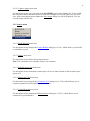
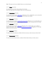
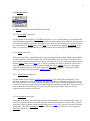
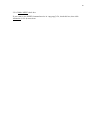
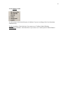
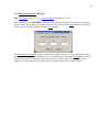
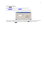
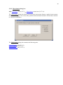
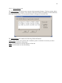
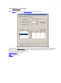
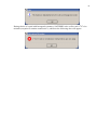
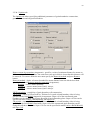
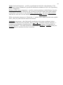
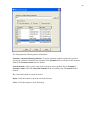
User’s Manual
SageMD2 Code
2
PREFACE ................................................................................................................. 5
1 INSTALLATION INSTRUCTIONS ..................................................................... 6
2 THE BASIC OPERATIONS OF SAGEMD2 MAIN WINDOW ......................... 7
2.1 Main Window...........................................................................................................................7
2.2 SAGEMD2 main window menus ...........................................................................................8
2.2.1 File menu ............................................................................................................................8
2.2.2 Edit menu............................................................................................................................9
2.2.3 View menu ........................................................................................................................10
2.2.4 Display menu ....................................................................................................................10
2.2.4.1 Parameters menu item ...............................................................................................10
2.2.4.2 Capture window menu item.......................................................................................10
2.2.4.3 Capture image menu item ..........................................................................................11
2.2.5 Lattice menu .....................................................................................................................11
2.2.5.1 Build/Rebuild menu item...........................................................................................11
2.2.5.2 Delete menu item .......................................................................................................11
2.2.5.3 Rebuild as unit cell menu item ..................................................................................11
2.2.5.4 Enumerate CSL menu item .......................................................................................11
2.2.5.5 Create Bicrystal menu item .......................................................................................11
2.2.6 Surface menu ....................................................................................................................12
2.2.6.1 Cleave surface menu item..........................................................................................12
2.2.6.2 Add atoms menu item ................................................................................................12
2.2.6.3 Super cell menu item .................................................................................................12
2.2.7 Operations menu ..............................................................................................................13
2.2.7.1 Select geom... menu item...........................................................................................13
2.2.7.2 Select all menu item ..................................................................................................13
2.2.7.3 Select none menu item...............................................................................................13
2.2.7.4 Select type menu item................................................................................................13
2.2.7.5 Select invert menu item .............................................................................................14
2.2.7.6 Select by plane menu items .......................................................................................14
2.2.7.7 Show selected only menu item ..................................................................................14
2.2.7.8 Show all menu item ...................................................................................................14
2.2.7.9 Scale menu item ........................................................................................................14
2.2.7.10 Move menu item ......................................................................................................14
2.2.7.11 Copy menu item ......................................................................................................14
2.2.7.12 Set type menu item ..................................................................................................14
2.2.7.13 Delete menu item .....................................................................................................15
2.2.7.14 Check lattice menu item ..........................................................................................15
2.2.7.15 Edit atoms menu item ..............................................................................................15
2.2.7.16 Add atoms menu item ..............................................................................................15
2.2.7.17 Add bonds checkbox ...............................................................................................15
2.2.7.18 Remove bonds checkbox .........................................................................................15
2.2.8 Tags menu.........................................................................................................................16
2.2.8.1 Create tag menu item .................................................................................................16
2.2.8.2 Select by tag menu item.............................................................................................16
2.2.8.3 Deselect by tag menu item ........................................................................................16
2.2.8.4 Delete tag menu item .................................................................................................16
2.2.9 Results menu ....................................................................................................................17
3
2.2.9.1 Local RDF menu item ...............................................................................................17
2.2.9.2 MSD menu item ........................................................................................................17
2.2.9.3 Temperature menu item .............................................................................................17
2.2.9.4 Animation menu item ................................................................................................17
2.2.9.5 Make MPEG check box.............................................................................................18
2.2.10 Window menu ................................................................................................................19
2.3 SAGEMD2 main window Toolbar .......................................................................................20
2.4 SAGEMD2 main window Control Panel .............................................................................22
2.5 Dialog boxes ...........................................................................................................................23
2.5.1 Display parameters dialog box .........................................................................................23
2.5.1.1 Atom tab ....................................................................................................................24
2.5.1.2 Bond tab.....................................................................................................................25
2.5.1.3 Misc tab .....................................................................................................................26
2.5.2 Lattice Builder dialog box .................................................................................................27
2.5.2.1 Space Group tab ........................................................................................................28
2.5.2.2 Cell tab.......................................................................................................................29
2.5.2.3 Asymmetric Cell tab ..................................................................................................30
2.5.2.4 Cell Vectors tab .........................................................................................................31
2.5.2.5 Unit Cell tab ..............................................................................................................32
2.5.2.6 Super Cell tab ............................................................................................................33
2.5.3 Cleave surface dialog box .................................................................................................34
2.5.3.1 Surface Box tab .........................................................................................................35
2.5.3.2 Options tab.................................................................................................................36
2.5.4 Add atom to surface dialog box .......................................................................................37
2.5.5 Make super cell dialog box ...............................................................................................37
2.5.6 Select dialog box ...............................................................................................................38
2.5.6.1 Box tab.......................................................................................................................39
2.5.6.2 Sphere tab ..................................................................................................................40
2.5.6.3 Cylinder tab ...............................................................................................................41
2.5.7 Select type dialog box .......................................................................................................42
2.5.8 Scale coordinates of atoms dialog box .............................................................................43
2.5.9 Input plane position dialog box ........................................................................................44
2.5.10 Move atoms dialog box ..................................................................................................45
2.5.11 Copy atoms dialog box ...................................................................................................46
2.5.12 Set type dialog box .........................................................................................................47
2.5.13 Check lattice dialog box ..................................................................................................48
2.5.13.1 Check distance tab ...................................................................................................49
2.5.13.2 Check Angles tab .....................................................................................................50
2.5.13.3 Surface distance tab .................................................................................................51
2.5.14 Add atoms dialog box .....................................................................................................52
2.5.15 List and edit atom positions dialog box ..........................................................................53
2.5.16 Create tag dialog box ......................................................................................................54
2.5.17 Select tag dialog box .......................................................................................................55
2.5.18 Deselect tag dialog box...................................................................................................55
2.5.19 Delete tag dialog box ......................................................................................................55
2.5.20 Local RDF dialog box .......................................................................................................56
2.5.21 Calculate temperature dialog box ..................................................................................57
2.5.22 Color dialog box ..............................................................................................................57
4
2.5.23 … Graph window.............................................................................................................58
2.5.24 Enumerate CSL dialog box ..............................................................................................59
2.5.24.1 Symmetrical tilt tab .................................................................................................60
2.5.24.2 Twist tab ..................................................................................................................62
2.5.24.3 Options tab...............................................................................................................63
2.5.25 Build interface dialog box ...............................................................................................65
2.5.25.1 Select structure tab ..................................................................................................66
2.5.25.2 Options tab...............................................................................................................67
2.5.26 Search structure dialog box
3 TUTORIALS ........................................................................................................ 69
3.1 Consecution of actions to build the grain boundaries ........................................................69
FAQs
5
Preface
This SAGEMD2 code is useful as pre-processor and post-processor for atomistic simulation
methods (i.e., “codes”), such as molecular dynamics (MD), Monte Carlo (MC), and quantum
density functional theory (DTF). SAGEMD2 includes an efficient and easy-to-use graphical user
interface (GUI) to enable various manipulations with atomic structures. This GUI provides a set
of tools for a user to design the material for calculation and to prepare the input for computations
and analyze the computational results.
The User Manual provided below will help you to become familiar with this software.
This User Manual consists of 2 Chapters. Chapter 1 explains requirements for using SAGEMD2
and describes the procedures for its installing and uninstalling. Chapter 2 acquaints with
software’s Main Window Menus (2.1), ToolBar (2.2), Control panel (2.3) and Dialog boxes (2.4)
Notations used in this Manual:
All names of menu items, dialog boxes, controls etc., indicated as underlined.
Example: Click the OK button.
All hyperlinks are accompanied by text references (in parentheses) to corresponding sections.
This makes the Manual easy to handle in both electronic and printed formats.
Example: Use this menu item to display the Lattice Builder dialog box (2.5.2), which allows you
to build or rebuild the crystal.
Warning: SAGEMD2 is in development process now, so some discrepancies may occur between
User Manual contents and the current software’s state. These discrepancies will be eliminated in
the next versions of the Manual.
6
1 Installation Instructions
Run sagemd2_setup.exe and follow instructions on your screen.
7
2 The Basic Operations of SAGEMD2 Main Window
2.1 Main Window
After starting SAGEMD2 and opening Zircon.SageMD2 file you will see window that is shown
below
8
2.2 SAGEMD2 main window menus
2.2.1 File menu
The File menu offers the following menu items:
New
Open
Close
Save
Save As
Export
Import
Database
Print
Exit
Creates a new document.
Opens an existing document.
Closes an opened document.
Saves an opened document using the same file name.
Saves an opened document to a specified file name.
Saves an opened document to a specified file format.
Opens a document using a specified file format.
Opens Search structure dialog box.
Prints a document.
Exits SAGEMD2
9
2.2.2 Edit menu
Undo
Redo
Copy
Cut
Paste
Reverse previous editing operation.
Reverse previous undo command action.
Copies data from the document to the clipboard.
Deletes data from the document and moves it to the clipboard
Pastes data from the clipboard into the document.
10
2.2.3 View menu
Parallel
Perspective
Front
Back
Left
Right
Top
Bottom
Fit
Reset
Zoom
Switch to parallel projection
Switch to perspective projection
Front view of the structure
Back view of the structure
Left view of the structure
Right view of the structure
Top view of the structure
Bottom view of the structure
Fit to view of the structure
Reset all viewing parameters
Zoom in on area
2.2.4 Display menu
The Display menu offers the following menu items:
2.2.4.1 Parameters menu item
Parameters menu item opens Display parameters dialog box (2.5.1), which allows you to build
the atomic bonds and control the appearance of the OpenGL objects.
Note: This menu item is not available if there are no atoms.
2.2.4.2 Capture window menu item
This menu item copies the SAGEMD2 screen onto bitmap file and opens Save image dialog
box. Use it to save the image into the file.
11
2.2.4.3 Capture image menu item
Use this menu item to copy any part of the SAGEMD2 screen to the bitmap file. To do it hold
the left mouse button and move mouse to draw the rectangle to select the part of the screen to
save. After releasing the mouse button the Save image dialog box will be displayed. Use it to
save the image into the file.
2.2.5 Lattice menu
2.2.5.1 Build/Rebuild menu item
Use this menu item to display the Lattice Builder dialog box (2.5.2), which allows you to build
or rebuild the crystal.
2.2.5.2 Delete menu item
Use this menu item to delete the current structure.
Note: The command is not available if there is no structure.
2.2.5.3 Rebuild as unit cell menu item
Use this menu item to transform current super cell to new unit cell and set the structure space
group to P1.
2.2.5.4 Enumerate CSL menu item
Use this menu item to display the Enumerate SCL dialog box (2.5.24), which allows you to
construct symmetrical twist and tilt grain boundaries.
2.2.5.5 Create Bicrystal menu item
Use this menu item to display the Build interface dialog box (2.5.25), which allows you to
construct bi-crystal interface.
12
2.2.6 Surface menu
2.2.6.1 Cleave surface menu item
Use this menu item to display the Cleave surface dialog box (2.5.3), which allows you to cleave
a crystal in a specified direction to create a surface.
2.2.6.2 Add atoms menu item
Use this menu item to display the Add atom to surface dialog box (2.5.4), which allows you to
add new atoms to the cleave surface.
2.2.6.3 Super cell menu item
Use this menu item to display the Make super cell dialog box (2.5.5) that allows you to build the
super cell defining the size of the super cell in terms of the numbers of the unit cell in each
direction of the specified surface.
13
2.2.7 Operations menu
The Operations menu offers the following menu items:
2.2.7.1 Select geom... menu item
Use this menu item to open Select dialog box (2.5.6), which allows you to select the atoms using
the Box (2.5.6.1), Sphere (2.5.6.2) and Cylinder (2.5.6.3) tabs of this dialog box.
2.2.7.2 Select all menu item
Use this menu item to select all atoms of the structure.
Note: This menu item is not available if all atoms have already been selected.
2.2.7.3 Select none menu item
Use this menu item to deselect all atoms of the structure.
Note: This menu item is not available if there are no selected atoms.
2.2.7.4 Select type menu item
Use this menu item to display Select type dialog box (2.5.7), which allows you to select the
atoms by the atom type.
Note: This menu item is not available if there are no atoms.
14
2.2.7.5 Select invert menu item
Use this menu item to toggle the current selection.
Note: This menu item is not available if there are no atoms.
2.2.7.6 Select by plane menu items
Use this menu item to display Input plane position dialog box (2.5.9), which allows you to
specify a plane to divide the structure into two parts.
2.2.7.7 Show selected only menu item
Use this menu item to display only the selected atoms and hide all the others.
Note: This menu item is not available if there are no selected atoms.
2.2.7.8 Show all menu item
Use this menu item to cancel the Show selected only (2.2.7.7) command action and display all
atoms of the structure.
Note: This menu item is not available if Show selected only command has not been executed
previously.
2.2.7.9 Scale menu item
Use this menu item to display Scale coordinate of atom dialog box (2.5.8), which allows you to
scale the atomic coordinates of the selected atoms.
Note: This menu item is not available if there are no selected atoms.
2.2.7.10 Move menu item
Use this menu item to display Move atoms dialog box (2.5.10), which allows you to move the
selected atoms to new positions.
Note: This menu item is not available if there are no selected atoms
2.2.7.11 Copy menu item
Use this menu item to display Copy atoms dialog box (2.5.11), which allows you to copy the
selected atoms to new positions.
Note: This menu item is not available if there are no selected atoms.
2.2.7.12 Set type menu item
Use this menu item to display Set type dialog box (2.5.12), which allows you to set the new type
to the selected atoms.
15
Note: This menu item is not available if there are no selected atoms.
2.2.7.13 Delete menu item
Use this menu item to delete the currently selected atoms.
Note: This menu item is not available if there are no selected atoms.
2.2.7.14 Check lattice menu item
Use this menu item to display Check lattice dialog box (2.5.13), which allows you to measure the
interatomic separation, the angles between atoms and the torsion angles.
2.2.7.15 Edit atoms menu item
Use this menu item to display List and edit atoms position dialog box (2.5.15), which allows you
to view and edit the atomic position and types. Also, it allows you to add and remove the atoms.
2.2.7.16 Add atoms menu item
Use this menu item to display Add atoms dialog box (2.5.14), which allows you to add new
atoms to the structure. Also, you can use List and edit atoms position dialog box (2.5.15) to add
atoms to the current structure.
2.2.7.17 Add bonds checkbox
To add the bond, check this box, and then click the two atoms, whose bond you wish to build.
2.2.7.18 Remove bonds checkbox
To remove the bond, check this box, and then click the bond, which you wish to remove.
16
2.2.8 Tags menu
If you intend to manipulate with the certain groups of atoms it is convenient to assign the tag
name to each group. Use the commands of Tags menu for work with the groups of atoms.
The Tags menu consists of the following menu items:
2.2.8.1 Create tag menu item
Use this menu item to display Create tag dialog box (2.5.16), which allows you to assign the tag
name and tag number to the group of selected atoms.
Note: This menu item is available, if some atoms are selected. Use one of Select geom…
(2.2.7.1), Select type (2.2.7.4) or Select by plane (2.2.7.6) menu items of Operations (2.2.7)
menu to select atoms. A different way of atoms selecting is to click directly the necessary atoms
in the current structure or, holding Shift key and left key of the mouse, to select a rectangle
region. Then all atoms in the interior of this region will be selected.
2.2.8.2 Select by tag menu item
Use this menu item to display Select by tag dialog box (2.5.17), which allows you to select the
atoms by the tag name.
Note: This menu item is available if the list of the tag names is not empty.
2.2.8.3 Deselect by tag menu item
Use this menu item to deselect atoms, which were selected by Select by tag command.
2.2.8.4 Delete tag menu item
Use this menu item to display Delete tag dialog box (2.5.19), which allows you to delete the tag
name from the list.
Note: This menu item is available if the list of the tag names is not empty.
17
2.2.9 Results menu
The Results menu offers the following menu items:
2.2.9.1 Local RDF menu item
Use this menu item to display Local RDF dialog box (2.5.20), which allows you to calculate the
radial distribution function (RDF) both for current structure and average result for structures that
were defined with the certain time step and saved in the files. In the latter case you must import
any structure file by Import menu item of File (2.2.1) menu before applying Local RDF menu
item. It’s necessary in order that the program might be able to do the proper intrinsic settings.
2.2.9.2 MSD menu item
This menu item allows calculating and viewing the graph of mean-square displacement (MSD)
of selected atoms versus file number. This operation makes sense for variety of structures that
were defined with the certain time step and saved in the files. At first, import one of the structure
files by Import menu item of File (2.2.1) menu, if you have not done it until now. Then select
some atoms for which you want to calculate MSD and choose MSD menu item, whereupon
select the required structure files in the appeared Open files dialog box. The graph of MSD
versus file number will appear in the MSD Graph (2.5.23) box.
2.2.9.3 Temperature menu item
Use this menu item to display Calculate temperature ( 2.5.21) dialog box that allows you to
calculate temperature of specified atoms. For this command it’s necessary to have the velocity
file with extension.v for current structure (or files, if you want to calculate temperature for a set
of structures that were defined with the certain time step and saved in the files). The velocity file
must contain the conversion factor into m/sec in the first string, and the array of velocity
components for all atoms of structure.
2.2.9.4 Animation menu item
This menu item allows you to animate structure transformation. This operation makes sense for
variety of structures that were defined with the certain time step and saved in the files. At first,
import one of the structure files by Import menu item of File (2.2.1) menu, if you have not done
it until now. Then click Animation menu item and select required structure files in appeared
Open files dialog box.
18
2.2.9.5 Make MPEG check box
If you want to save MPEG formatted movies in “mpg.mpg” file, check this box, then click
Animation (2.2.9.4) menu item.
19
2.2.10 Window menu
Use this menu for the desired layout of windows if you are working with a few documents
simultaneously.
Toolbar checkbox: Check this box if you want to see Toolbar in Main Window.
Control panel checkbox: Check this box if you want to see Control panel in Main Window.
20
2.3 SAGEMD2 main window Toolbar
The toolbar is displayed across the top of the application window, below the menu bar. The
toolbar provides quick mouse access to many tools used in SAGEMD2.
Click to
Create new document.
Open document file.
Save document.
Save document to another file.
Undo.
Redo.
Print snapshot image.
Remove selected data from the document and store it on the clipboard.
Copy the selection to the clipboard.
Insert the contents of the clipboard into the document.
Switch to perspective projection.
Switch to parallel projection.
View structure from the front.
View structure from behind.
View structure from the left.
View structure from the right.
View structure from the top.
21
View structure from below.
Reset view.
Fit image to be visible.
22
2.4 SAGEMD2 main window Control Panel
Control panel is intended for controlling and setting parameters for image on the screen .Control
panel consists of four group boxes.
Angles group box allows you to rotate atomic structure relative to the axes X, Y, Z by input of
the appropriate values of angle (in degrees) into corresponding fields, or turning corresponding
dialers, and to increase (decrease) image by input of the appropriate coefficient into Zoom field.
Colors group box allows you to set colors and tints of window background, top and bottom of
background. Click the appropriate color box to display Color dialog box (2.5.22) and choose the
new color using this dialog.
Settings group box: the fog check box allows you to set fog effect on the structure. Use turbo
check box to rotate structure quickly.
Display group box contains controls for governing the appearance of the structure.
Use the Quality slider to control rendering quality of the OpenGL objects. Sometimes, high
value of this parameter may result in lower performance of your computer. In such case you
should decrease the value of this parameter.
Use the check box CPK view to display atoms rendered as spheres sized to the Van der Waals
(VDW) radii.
23
2.5 Dialog boxes
The most of menu items open the various dialog boxes that enable entering the input data and
setting the essential parameters. The dialog boxes are itemized below in this chapter. All dialog
boxes are included into an individual chapter for both hyperlinks and text references usability.
2.5.1 Display parameters dialog box
Path: Display menu (2.2.4)
Parameters menu item (2.2.4.1).
Use this dialog box to build the atomic bonds and to control the atom size and colors. Also, the
dialog allows you to change the appearance of the bonds and their radii. Using this dialog you
can show or hide the bonds and choose the background color. The Display parameters dialog has
the following tabs and buttons:
Atom tab (2.5.1.1)
Bond tab (2.5.1.2)
Misc tab (2.5.1.3)
Close: use this button to close the dialog.
Help: use this button for help about the currently active tab.
24
2.5.1.1 Atom tab
Use this tab to change the atom sizes, colors and rendering quality of the OpenGL graphics.
To change the atom colors, just click on the color you wish to change. The Color dialog box
(2.5.22) will be displayed. Set the desired color and click Accept button to close the Color
dialog.
To change the atom size, click on the value of atomic radius in the Size column. The dialog will
be displayed that allows you to specify the new atomic radius.
Note: The atomic size is in Angstrom units. The default atomic radius equals its covalent radius.
Use the Quality slider to control rendering quality of the OpenGL objects. Sometimes, high
value of this parameter may result in lower performance of your computer. In such case you
should decrease the value of this parameter.
Use Make same size button to make all atomic radii equal to the radius value of the currently
selected atom.
Close: use this button to close the dialog.
Help: use this button to display this page.
25
2.5.1.2 Bond tab
Use this tab to build the atomic bonds, change bond radii, show or hide the bonds image.
This tab has the following boxes and buttons:
Build bonds: group box allows you to create bonds between two atoms if the following criteria
are met:
min factor * covalent radii sum < distance < max factor * covalent radii sum
where distance= distance between two atoms forming the bond. To build the bonds, click the
Build button. If no bonds are shown try other values of the min and max factors.
Bond radius: Allows you to specify the bond radius as a fraction of the radius of atoms forming
the bond. The bond radii are within 0-100 range.
Show bonds: Check this box to display the bond images or uncheck to hide it.
Auto rebuild: Uncheck this box to build or remove the bonds manually. How to add or remove
bonds manually, see Add bonds (2.2.7.17) and Remove bonds (2.2.7.18) checkboxes of
Operations (2.2.7) menu.
CPK view: Check this box to display atoms rendered as spheres sized to the van der Waals
(VDW) radii.
Close: use this button to close the dialog.
Help: use this button to display this page.
26
2.5.1.3 Misc tab
Use this tab to change various miscellaneous parameters.
This tab has the following boxes and buttons:
Colors: group box allows you to change the window background colors and the color used to
display the selected atoms. Just click the appropriate color box to display Color dialog box
(2.5.22) and choose the new color using this dialog. Uncheck Auto checkbox for setting bonds
color manually
Projections: Use these radio buttons to switch between orthogonal and perspective projections.
Contour: Allows you to specify how the contour around the crystal will be displayed.
Select Hide to hide the contour image.
Select Unit cell to display the contour around the unit cell.
Select Lattice to display the contour around the whole crystal.
Close: use this button to close the dialog box.
Help: use this button to display this page.
27
2.5.2 Lattice Builder dialog box
Path: Lattice menu (2.2.5)
Build/Rebuild menu item (2.2.5.1).
You can use the Lattice Builder dialog to create a new crystal, to modify the space group
number, the unit cell parameters, the primitive cell vectors and the box size. Also, using Lattice
Builder dialog box you can add and remove atoms from the unit cell or change their types.
The Lattice Builder dialog contains the following tabs and buttons:
Space Groups tab (2.5.2.1)
Cell tab (2.5.2.2)
Asymmetric Cell tab (2.5.2.3)
Cell vectors tab (2.5.2.4)
Unit Cell tab (2.5.2.5)
SuperCell tab (2.5.2.6)
OK: use this button to build or rebuild the crystal using data from the dialog tabs and to close the
dialog.
Cancel: use this button to close the dialog without building or rebuilding the crystal.
Apply Now: the same as OK but the dialog will not be closed.
Help: use this button for help about the active tab.
28
2.5.2.1 Space Group tab
The Space Groups tab allows you to specify or modify the space group and space group settings
for the structure that you wish to build or rebuild.
The Space Groups tab has the following boxes:
Group number: You can specify a space group number by editing this box or using the spin
buttons. When you change the group number the contents of the Select space group box will be
changed also and vice versa.
Select space group allows you to select the required space group from the dropdown list.
Note: the contents of Group number box will be changed to show the number of the selected
space group.
Select groups to show: use this box to select the crystal system, which space groups you wish to
see in the Select space group box. Note that the contents of the group number box will be
restricted to show the space group numbers of the selected crystal system.
29
2.5.2.2 Cell tab
The Cell tab allows you to specify the length and relative orientation of the unit cell vectors in
space. The whole crystal can be built by means of translation of the unit cell along the unit cell
vectors [see Super Cell tab (2.5.2.6)]. The space group symmetry can restrict the lattice
parameters to the predefined values. In such cases some parameters will not be available for
editing.
a, b, c: The length of the unit cell vectors a, b, c.
alpha: The angle between b and c vectors.
beta: The angle between a and c vectors.
gamma: The angle between a and b vectors.
Crystal system: Can be one of the seven crystal systems (triclinic, monoclinic, orthorhombic,
tetragonal, trigonal, hexagonal or cubic. Some of the space groups of the trigonal crystal system
can have extensions such as hexagonal or rhombohedral axes).
30
2.5.2.3 Asymmetric Cell tab
Asymmetric Cell tab allows you to build the whole unit cell by using the space group symmetry
operations for each atom in the asymmetric cell.
Asymmetric Cell tab has the following data fields:
Atom positions (fractional): Displays the position and type for each atom in the asymmetric cell.
To edit the atom position or type you can click on the corresponding row in this field.
Edit positions: Allows you to modify the atom positions. x, y and z are the fractional coordinates
of the atom. Their values must be numbers from 0 to 1. If you specify the other value, the error
message will be displayed.
Change Atom: Allows you to modify the current atom type by selecting a new atom from the
dropdown list.
Add Atom: Use this button to add new atom to the structure. The atom type is specified in the
Change atom box. The default coordinates of the atom are x=0, y=0, z=0. Use the Edit positions
boxes to modify these values.
Delete Atom: Click this button to remove an atom from the asymmetric cell
Clear: Click this button to remove all atoms from the asymmetric cell.
Build unit cell: Click this button to build the whole unit cell. The number of atoms and their
positions in the unit cell depend on the space group settings [see Space Group tab (2.5.2.1)].
31
2.5.2.4 Cell Vectors tab
Use this tab to see the unit cell vectors. The edit boxes of this dialog have the read only
permission. To edit the unit cell vectors you can use the Cell (2.5.2.2) tab.
ax, ay, az, bx, by, bz, cx, cy, cz: are the Cartesian components of the a, b, c unit cell vectors.
32
2.5.2.5 Unit Cell tab
Unit Cell tab allows you to view and edit atom positions in the unit cell. Also, you can change
the atom type and add atoms to or remove from the unit cell. Generally, you build the unit cell
using the Asymmetric Cell (2.5.2.3) tab. You can alternatively define the atom positions and
their types using this tab. In this case you do not require knowing the space group information
and asymmetric cell settings.
The Unit Cell tab has the following data fields:
Atom positions (fractional): Displays the position and type for each atom in the unit cell. To edit
the atom position or type you can click on the corresponding row in this field.
Edit positions: Allows you to modify the atom positions. x, y and z are the fractional coordinates
of the atom. Their values must be numbers from 0 to 1. If you specify the other value, the error
message will be displayed.
Change Atom: Allows you to modify the current atom type by selecting the new atom from the
dropdown list.
Add Atom: Use this button to add a new atom to the structure. Atom type is specified in the
Change atom box. The default coordinates of the atom are x=0, y=0, z=0. Use the Edit positions
boxes to modify these values.
Delete Atom: Click this button to remove an atom from the unit cell.
Clear: Click this button to remove all atoms from the unit cell.
33
2.5.2.6 Super Cell tab
The Super Cell tab allows you to create a supercell (crystal) from the current unit cell. Also, you
can use this tab to rebuild the supercell. You define the size of the supercell in terms of the
numbers of the unit cell in each direction. The fractional coordinates of the supercell are given in
terms of the unit cell vectors. For example, the fractional coordinates of atoms in 2x2x2 supercell
are within the range from 0 to1.9999... . The atoms in the original unit cell have their coordinates
within the range from 0 to 0.9999... .
The Super Cell tab has the following fields:
Number of unit cells in a direction: Allows you to specify the range of the supercell along a
vector of the unit cell.
Number of unit cells in b direction: Allows you to specify the range of the supercell along b
vector of the unit cell.
Number of unit cells in c direction: Allows you to specify the range of the supercell along c
vector of the unit cell.
Box size: Defines the periodic box size for MD simulation.
Allow me to change box size manually: This option will be realized in the next SAGEMD2
version.
34
2.5.3 Cleave surface dialog box
Path: Surface menu (2.2.6)
Cleave surface menu item (2.2.6.1).
Cleave surface dialog box has the following tabs and buttons:
Surface Box tab (2.5.3.1)
Options tab (2.5.3.2)
OK: use this button to build or rebuild cleave surface using data from the dialog tabs and to close
the dialog.
Cancel: use this button to close the dialog without building or rebuilding the cleave surface.
35
2.5.3.1 Surface Box tab
Surface Box tab has the next fields and buttons:
Miller indexes: Specifies the cleave plane using the Miller indices h, k and l separated by spaces.
Top: Specifies the distance from the origin to the top of the cleave slab as either:
Fractional: a fraction of the D-spacing of the Miller family of the Cleave plane.
Angstrom: an absolute value in Angstroms.
Depth: Specifies the thickness of the cleave slab either as a fraction of the D-spacing or in
Angstroms.
Components: In these fields you may see the calculated directions of the generating vectors for
the Cleave plane, U and V.
Vectors length: In these fields you may see the calculated length of the generating vectors for the
Cleave plane, U and V.
Angle: In this field you may see the calculated angle between vectors U and V.
36
2.5.3.2 Options tab
The main tool for choosing of surface vectors for two crystals is tab Options, dialog
Cleave Surface.
Click Generate button to generate table. The table consists of four columns: Length U, Length V
- lengths of surface vectors, Alpha - angle between surface vectors and S - area of surface cell.
Vectors table is generated according to limiting conditions, which are to be entered in the fields
MaxLength - maximum vector length, Angel1 and Angel2 - minimum and maximum angle
between vectors.
In order to display vectors coordinates instead of their lengths in the table it is necessary to select
(click) check box Fractional.
In order to find the cell most similar to another cell by dimensions, area or angle the search by
set parameters is realized in another crystal dialog. It is necessary to enter vector parameters in
the dialog field Find vectors closest to and click Find button. The cell with the most similar
parameters will be highlighted in the table.
The table lines are always sorted by area of surface cell, this makes search of cells with similar
area easier.
After the most similar vectors are found it is necessary to click button Set vectors. You will be
automatically switched to tab Surface Box from Options and initial cell will be displayed on
visualizer screen.
Note: it is recommended to keep dialogs Cleave surface open until both surfaces are built.
37
2.5.4 Add atom to surface dialog box
Path: Surface menu (2.2.6)
Add atoms menu item (2.2.6.2).
This dialog box allows you to specify the type and coordinates of the atom that you wish to add
to the specified cleave surface.
2.5.5 Make super cell dialog box
Path: Surface menu (2.2.6)
Super cell menu item (2.2.6.3).
This dialog box allows you to create a super sell (surface) from the current unit cell. Set the size
of the super cell in terms of the numbers of the unit cell in each direction of surface and click OK
button.
38
2.5.6 Select dialog box
Path: Operations menu (2.2.7)
Select geom… menu item (2.2.7.1).
This dialog allows you to select atoms, which are inside the box, sphere or cylinder.
The Select dialog box contains the following tabs and buttons:
Box tab (see 2.5.6.1)
Sphere tab (see 2.5.6.2)
Cylinder tab (see 2.5.6.3)
Select invert: use this button to toggle the current selection.
Select all: use this button to select all atoms of the structure.
Select none: use this button to deselect all atoms of the structure.
Close: use this button to close this dialog.
Help: use this button for help about the currently active tab.
39
2.5.6.1 Box tab
This tab allows you to specify the box, which contains the atoms you wish to select. To specify
the box, you need to define the coordinates of two vertices of this box. These vertices are the end
points of the largest diagonal of the box.
This tab has the following data fields:
X1, Y1, Z1: Allows you to specify the coordinates of the first vertex in the currently active
coordinate system.
X2, Y2, Z2: Allows you to specify the coordinates of the second vertex in the currently active
coordinate system.
Coordinate system: Allows you to specify which coordinate system to use to define the box.
Apply: Click this button to select the atoms, which are inside the specified box.
40
2.5.6.2 Sphere tab
This tab allows you to specify the sphere, which contains the atoms you wish to select. To
specify the sphere, you need to define coordinates of the sphere center and the sphere radius.
This tab has the following data fields:
xc, yc, zc: Allows you to specify the coordinates of the sphere center.
R: Allows you to specify the sphere radius.
Coordinate system: Allows you to specify which coordinate system to use to define the sphere.
Apply: Click this button to select the atoms, which are inside the specified sphere.
41
2.5.6.3 Cylinder tab
This tab allows you to specify the cylinder, which contains the atoms you wish to select. To
specify the cylinder, you need to define the cylinder axis, the coordinates of the cylinder base
center, the cylinder radius and height.
This tab has the following data fields:
Axis along z: Allows you to select from dropdown list the axis along which the cylinder will be
orientated.
xc, yc, zc: Allows you to specify the coordinates of the cylinder base center.
R: Allows you to specify the cylinder radius.
H: Allows you to specify the cylinder height.
Coordinate system: Allows you to specify which coordinate system to use to define the sphere.
Apply: Click this button to select the atoms, which are inside the specified cylinder.
42
2.5.7 Select type dialog box
Path: Operations menu (2.2.7)
Select type menu item (2.2.7.4).
Use this dialog to select atoms by the atom type.
Select the atomic symbol from the dropdown list and click OK button. All atoms of the selected
type will be selected.
43
2.5.8 Scale coordinates of atoms dialog box
Path: Operations menu (2.2.7)
Scale menu item (2.2.7.9).
Use this dialog to scale coordinates of the selected atoms by the factor you defined.
The dialog has the following boxes and buttons:
X scale factor: Allows you to specify the factor to scale X coordinates of the selected atoms.
Y scale factor: Allows you to specify the factor to scale Y coordinates of the selected atoms.
Z scale factor: Allows you to specify the factor to scale Z coordinates of the selected atoms.
use the same for all directions: Check this box to scale all the coordinate components by the
same factor.
OK: Click this button to scale the atomic coordinates and close the dialog.
Cancel: Click this button to close the dialog without the scaling.
44
2.5.9 Input plane position dialog box
Path: Operations menu (2.2.7)
Select by plane menu item (2.2.7.6).
This command of the SAGEMD2 code allows you to specify a plane that divides the structure
into two parts. One of these parts will be selected after you click the Select button of this dialog.
Also you can close this dialog by clicking Close button.
The Input plane position dialog box contains three fields a, b and c, where you can specify the
plane position in fractional coordinate system. After that you can click the Select button, and the
selected atoms will be displayed by the main window in yellow color. If you want to select
another part of the structure just click Select invert menu item of the operation menu.
45
2.5.10 Move atoms dialog box
Path: Operations menu (2.2.7)
Move menu item (2.2.7.10).
Use this dialog to move selected atoms by the shift vector you define. All the vector components
are in the fractional coordinate system. x is directed along a, y - along b, and z - along c vectors
of the unit cell.
The dialog has the following boxes and buttons:
X shift: Allows you to specify the shift along a vector of the unit cell.
Y shift: Allows you to specify the shift along b vector of the unit cell.
Z shift: Allows you to specify the shift along c vector of the unit cell.
use the same for all directions: Check this box to move the selected atoms by the same shift in all
directions.
OK: Click this button to move the selected atoms and close the dialog.
Cancel: Click this button to close the dialog without the moving.
46
2.5.11 Copy atoms dialog box
Path: Operations menu (2.2.7)
Copy menu item (2.2.7.11).
This dialog allows you to translate the selected group of atoms in any direction and repeat the
displacement one or more times. All the displacement vector components are in the fractional
coordinate system. X is directed along a, y - along b, and z - along c vectors of the unit cell.
The dialog has the following boxes and buttons:
a: Allows you to specify the shift along a vector of the unit cell.
b: Allows you to specify the shift along b vector of the unit cell.
c: Allows you to specify the shift along c vector of the unit cell.
rep: Allows you to specify how many times to repeat this operation.
OK: Click this button to copy the selected atoms and close the dialog.
Cancel: Click this button to close the dialog without the copying.
47
2.5.12 Set type dialog box
Path: Operations menu (2.2.7)
Set type menu item (2.2.7.12).
Use this dialog to set the type, which you assign to the selected atoms.
Select the atomic symbol from the dropdown list. Then click OK button to set the new type to all
selected atoms or click Cancel button to close the dialog without setting of a new type.
48
2.5.13 Check lattice dialog box
Path: Operations menu (2.2.7)
Check lattice menu item (2.2.7.14).
The Check lattice dialog box allows you to measure interatomic distance, angles between atoms
and the torsion angles. You can see the positions and interatomic distance in fractional, reduced
or Cartesian coordinates.
The Check lattice dialog box contains the following tabs:
Check Distance tab (2.5.13.1)
Check Angles tab (2.5.13.2)
Surface distance tab (2.5.13.3)
49
2.5.13.1 Check distance tab
The Check distance tab allows you to measure the interatomic distance. Click two atoms, whose
separation you wish to measure. The edit box of this tab will show the number of selected atoms,
their types and positions. The interatomic distance will appear in the third line.
The Check distance tab contains the following fields and buttons:
Choose units: allows you to choose the coordinate system, in which it is necessary to show
separation and positions of the atoms.
Clear: use this button to clear the edit box of this tab.
Close: use this button to close this dialog.
50
2.5.13.2 Check Angles tab
The Check Angles tab allows you to measure the angles between atoms and the torsion angles.
Click three atoms to measure the angle between them. At first you need to click the atom, which
is the vertex of the angle. To measure the torsion angle, you must check the Torsion angles check
box. Then click two atoms B and C, whose angle you wish to measure. Then click two atoms A
and D, which are bonded to B and C, respectively. In the edit box of this tab, there will be the
number of selected atoms, their types and positions. The last line will show the angle between
atoms or the torsion angle.
The Check Angles tab contains the following fields and buttons:
Choose units: allows choosing the coordinate system, in which it is necessary to show separation
and positions of the atoms.
Clear: use this button to clear the edit box of this tab.
Close: use this button to close this dialog.
Torsion angles: use this check box to measure the torsion angles.
51
2.5.13.3 Surface distance tab
The Surface distance tab allows you to measure the distance between atom and specified surface.
Create the surface and click atom, whose separation you wish to measure. The edit box of this
tab will show the number of selected atoms, its type and position. The distance will appear in the
second line.
Choose units: allows you to choose the coordinate system, in which it is necessary to show
separation and positions of the atoms.
Clear: use this button to clear the edit box of this tab.
Close: use this button to close this dialog.
52
2.5.14 Add atoms dialog box
Path: Operations menu (2.2.7)
Add atoms menu item (2.2.7.16).
The Add atoms dialog allows you to add new atoms to the structure. You can specify the atomic
positions and types.
The Add atoms dialog contains the following fields and buttons:
Edit positions: Allows you to modify the atom positions.
Coordinate system: Use this field to choose the coordinate system. You can choose Cartesian,
reduced or fractional coordinates.
Change Atom: Allows you to modify the current atom type by selecting the new atom from the
dropdown list.
Add: Use this button to add the new atom to the structure.
Close: Click this button to close this dialog.
53
2.5.15 List and edit atom positions dialog box
Path: Operations menu (2.2.7)
Edit atoms menu item (2.2.7.15).
This dialog allows you to view and edit the atomic positions and types. Also, it allows you to add
and remove the atoms. Using this dialog you can see and edit the position of individual atom in
the opened document. Just click on the atom in the structure image and you can see the selected
line with atomic position in the Atom positions field. You can edit the coordinates of the selected
atom using the Edit positions boxes and change the atom type using the Change atom dropdown
list. Also you can select the individual atom in the Atom positions field and it will be selected in
the structure image.
The List and edit atoms position dialog contains the following fields and buttons:
Atom positions: Displays the position and type for each atom of the current structure. To see
location of the atom in the structure image or to edit the atom position and type you can click on
the corresponding row in this field.
Edit positions: Allows you to modify the atom positions.
Note: you need to click Apply button to apply your edit action.
Apply: Use this button to change the atom position accordingly to the values in the Edit
positions boxes.
Change atom: Allows you to modify the current atom type by selecting a new atom from the
dropdown list.
Coordinate system: Use this box to choose the coordinate system. You can choose Cartesian,
reduced or fractional coordinates.
Add Atom: Use this button to add a new atom to the structure. The atom type is specified in the
Change atom box. The default coordinates of the atom are x=0, y=0, z=0. Use the Edit positions
boxes to modify these values.
Delete Atom: Click this button to remove an atom from the structure.
Close: Click this button to close this dialog.
54
2.5.16 Create tag dialog box
Path: Tags menu (2.2.8)
Create group(Tag…) menu item (2.2.8.1).
The Create tag dialog box allows you to assign a tag name to the group of selected atoms and to
add this tag name to the list.
The Create Tag dialog contains the following fields and buttons:
Tag name: Use this box to input a tag name that you wish to assign to the group of selected
atoms. By default this name is GroupN, where N is number of tag name in the list, but you may
input your own name.
Tag number is the number of a tag name in the list.
OK: Click this button to assign the tag number to selected atoms and close the dialog.
Cancel: Click this button to close the dialog without the assigning tag number.
55
2.5.17 Select tag dialog box
Path: Tags menu (2.2.8)
Select by tag menu item (2.2.8.2).
Use this dialog box to select atoms by the tag name. Choose the tag name from dropdown list
and click OK button.
2.5.18 Deselect tag dialog box
Path: Groups (Tags) menu (2.2.8)
Deselect by tag menu item (2.2.8.3).
Use this dialog box to deselect atoms by the tag name. Choose the tag name from dropdown list
and click OK button.
2.5.19 Delete tag dialog box
Path: Tags menu (2.2.8)
Delete tag menu item (2.2.8.4).
Use this dialog box to delete a tag name from the list. Choose the tag name from dropdown list
and click OK button.
56
2.5.20 Local RDF dialog box
Path: Results menu (2.2.9)
Local RDF menu item (2.2.9.1).
The Local Rdf dialog box has the following fields and buttons:
Central atom: Allows you to specify a number of an atom relative to which Rdf is calculated. If
you set atom number to be 0, then Rdf is calculated relative to atom which is the nearest to the
geometric center of current structure and has the type selected in the dropdown list Type1.
Type1: Allows you to choose the type of the atom relative to which Rdf is calculated. If the
chosen type does not agree with the type of the specified center atom, an error massage will be
returned.
Type2: Allows you to choose the type of the atoms for which Rdf is calculated.
Rmin(A): Allows you to specify the minimal distance from the center atom.
Rmax(A): Allows you to specify the maximal distance from the center atom.
dr(A): Allows you to specify distance increment.
Coordination numbers: Check this box if you want to calculate coordinate numbers. Uncheck
this box if you want to calculate normalized Rdf.
Calculate: Click this button to calculate Rdf for the input data. Rdf graph will appear in the RDF
Graph (2.5.23) window.
From files: Allows you to choose list of structure files for Rdf averaging. Click this button to
open standard dialog box Open files.
Close: Click this button to close this dialog.
57
2.5.21 Calculate temperature dialog box
Path: Results menu (2.2.9)
Temperature menu item (2.2.9.3).
The Calculate temperature dialog box has the following fields and buttons:
Type: Allows you to choose the type of atoms, for which temperature is calculated.
Temperature: this is the field for temperature output for current structure.
From files: Allows you to choose a list of velocity files for calculating the temperature. Click this
button to open standard dialog box Open files. If you have chosen the list of velocity files, the
graph of temperature versus file index will appear in the Temperature Graph (2.5.23) window.
Calculate: Click this button to calculate temperature for the current structure.
Cancel: Click this button to close this dialog.
2.5.22 Color dialog box
58
2.5.23 … Graph window
All graphs obtained in Results menu (2.2.9) are outputted into …Graph window.
…Graph box contains the graph field and some buttons:
Close: Click this button to close …Graph box.
Export: Click this button to save graph data in the text file. Specify the file name in the appeared
Export graph data dialog box.
Save image: Click this button to save graph image in appropriate format (*.bmp, *.ppm, *.xpm,
*.gif, *.xbm). Specify the file name and type in the appeared Save image dialog box.
The other buttons are intended for graph objects editing and has the obvious sense. You may edit
the graph objects in two ways. For example, if you want to edit Graph title, you may click the
title field on the graph or click the corresponding button. In both cases Set title text dialog box
will appear:
59
2.5.24 Enumerate CSL dialog box
Path: Lattice menu (2.2.5)
Enumerate CSL menu item (2.2.5.4).
You can use the Enumerate CSL dialog to construct symmetrical twist and tilt grain boundaries.
In order to activate this dialog, a crystal must be constructed/opened in the main window of
visualizer. Dialog consists of three tabs:
Symmetrical tilt tab (2.5.24.1)
Twist tab (2.5.24.2)
Options tab (2.5.24.3)
60
2.5.24.1 Symmetrical tilt tab
Tab Symmetrical tilt allows construction of symmetrical tilt grain boundaries.
The only parameter which must be specified by the user in the field Max sigma (twin index) for
calculation of all possible tilt grain boundaries is the Σ maximum value. I.e. up to which Σ value
list of tilt grain boundaries with CSL will be displayed. Σ is calculated by volume ratio of CSL
elementary cell and crystal elementary cell. Maximum value of this parameter is limited by the
code and equals 49, because grain boundaries Σ > 49 have no physical application mostly.
After specifying of Σ parameter and pressing Enumerate button, in the field below dialog will
appear list of grain boundaries designated by Miller indices and Σ value. At selection of any line
in this list, in the field Tilt CSL vectors, coordinates of CSL vectors in matrix form will be
displayed (in fractional) and grain boundaries indices and normal indices will be displayed in the
fields Plane (h k l) and Normal [U V W]. It is necessary to choose required plane and press Build
button for construction of tilt grain boundary. Click Undo Build button and then select a listbox
item to build another configuration.
Note: Symmetry of selected crystal must be cubic or hexagonal, otherwise, the following
message box will appear after attempt to calculate possible CSL:
61
During choice of crystal with hexagonal symmetry, SAGEMD2 code verifies ratio c2/a2 to be
rational (exception is rotation around axis с), otherwise the following alert will appear:
62
2.5.24.2 Twist tab
The Twist tab allows construction of symmetrical twist grain boundaries.
User can specify indices (hkl) for boundary plane or indices [UVW] for rotation axis in the fields
Plane (h k l) or Normal [U V W] accordingly for construction of symmetrical twist grain
boundaries. These fields are interconnected, so the indices of one field are recalculated
automatically after changing indices in another one. The second parameter necessary for
determination is specified in the field Max planar sigma. Its value limits list of possible angles
for construction of 3D CSL cell and determined by the density of coincident sites on the grain
boundary plain.
After specifying of the parameters it is necessary to press Enumerate button. List of possible
CSL cells will appear in the left lower field of the tab. The cells in this list are determined by the
rotation angle around normal [UVW] and surface Σ.
After selection of any line in this list, in the field Twist CSL vectors coordinates of CSL vectors
will be displayed in matrix form (each column specifies CSL vector), and value specifying
volume ratio of CSL cell and elementary crystal cell will be displayed in the field Sigma.
It is necessary to press Build button for construction of required twist grain boundary.
63
2.5.24.3 Options tab
The Options tab allows specifying additional parameters of grain boundaries construction,
general for twist and tilt grain boundaries.
Remove atoms by separation (Angstroms) - specifies a value of minimum distance for atoms on
different sides of boundary plane. One atom from each pair which is closer than this distance will
be removed. To remove atoms the user must specify the Removal method and press Remove
button.
Removal method - choice of removal method for atoms distance between which closer than
specified in the field Remove atoms by separation (Angstroms):
Random - remove atoms randomly,
Crystal_1 - remove atoms from crystal 1 always,
Crystal_2 - remove atoms from crystal 2 always.
2D/3D periodicity - periodicity of grain boundary cell construction:
2D periodic - choice of 2D periodicity. Thickness of crystal on both boundary sides is being
specified in the field Width (Angstrom) in angstroms. Super cell of the constructed grain
boundary can be changed only in two directions lying in boundary plane. Super cell size can be
specified in menu Lattice->Build/Rebuild, tab Super Cell.
3D periodic - choice of 3D periodicity. Thickness of crystal on both boundary sides is being
specified in the field Width (Fractional). Super cell of the constructed grain boundary can be
changed in all three directions. Super Cell size can be specified in menu Lattice->Build/Rebuild,
tab Super Cell.
64
Width (Fractional/Angstrom) – specifies crystal depth on both sides of the boundary. If 3D
periodicity is chosen, parameter is specified in fractional coordinates of CSL cell, if periodicity
is 2D - in angstroms.
Distance to label atoms (Angstroms) – specifies value determining on which distance from the
boundary the atoms will be labeled by tag. In order to select these atoms after grain boundary
construction it is necessary to enter menu Tags->Select by Tag… and choose Near interface
from the list. Also user can view labeled atoms by pressing Show interface button.
While exporting the structure in cif format the “1” symbol will be added to the the atom symbol
in the _atom_site_label field for atoms near interface.
Translation (Angstroms) – this field specifies translation of the atoms coordinates in three
directions on both sides of the boundary. Where A and B - translation along the boundary, C translation perpendicular to boundary plane. If 2D periodicity is chosen, it is impossible to
specify translation С. User must specify the crystal number (Crystal_1 or Crystal_2) and press
Translate button to translate the atoms coordinates.
65
2.5.25 Build interface dialog box
Path: Lattice menu (2.2.5)
Create Bicrystal menu item (2.2.5.5).
After building of “surface cells” similar by geometry and dimensions, user needs to open Build
interface dialog in which it is necessary to choose two windows with structures (built surfaces),
which will form bi-crystal. The windows are selected in drop down menus Crystal_1 and
Crystal_2. It is necessary to note, that window name corresponds to opened/saved file.
Dialog consists of two tabs:
Select structure tab (2.5.25.1)
Options tab (2.5.25.2)
66
2.5.25.1 Select structure tab
In order to provide periodical boundary conditions of obtained bi-crystal, it is necessary to
change translation vectors and angle between them so, that their values will coincide. Dialog
Build interface offers the following options for bi-crystal building in field Unit Cell as:
a. Crystal_1 - reducing of the second crystal vectors to the dimensions of the first one,
b. Crystal_2 - reducing of the first crystal vectors to the dimensions of the second one,
c. Average - reducing of the both crystals vectors to average quantity.
In order to keep the cell volume the same after changing the crystal geometry it is necessary to
check Keep Density Constant. The volume will be the same because of ranging of atom
coordinates along vector normal to boundary plane.
User can define distance in angstroms between planes of two crystals in interface area in the
field Vacuum gap. So the distance between two crystals will be set during bi-crystal building.
It is necessary to click OK button after setting of all the parameters for bi-crystal building in 3D
window.
67
2.5.25.2 Options tab
Tab Options allows setting additional parameters for interface building. These parameters are of
the same kind as at grain boundary building.
The fields of the tab are the following:
Minimum separation (Angstr) - sets value of minimum distance for atoms on the different sides
of the boundary plane. One atom which is closer than this distance is removed from each pair of
atoms.
Removal method - choice of method of removal for atoms the distance between which is less
then value set in the field Minimum separation (Angstroms):
Random - atoms are removed randomly,
Crystal_1 - atoms always removed from crystal 1,
Crystal_2 - atoms always removed from crystal 2.
Translation (Angstroms) - this field sets shift of the atom coordinates in three directions from the
both sides of the boundary. Where A and B - shift along the boundary, C – shift perpendicular to
the boundary plane.
2.5.26 Search structure dialog box
This dialog allows you to find and open structure in the SageMD2 structure database.
68
The dialog has the following boxes and buttons:
Structure contains following elements: Type the elements symbol separated by space to
specify the chemical formula of the structure if the Formula field is checked or the structure
name if the Structure name field is cheked.
Search method: Allows you to specify the search structure method. Select Formula or
Structure name fields.The Only this elements field is available only if Formula field is
cheked.
Go: Click this button to search structures.
Open: Click this button to open the selected structure.
Close: Click this button to close the dialog.
69
3 Tutorials
3.1 Consecution of actions to build the grain boundaries
1.
2.
3.
4.
5.
6.
7.
8.
Open or import the structure;
Open Lattice menu and select Enumerate CSL menu item;
Switch to Options tab of the Enumerate CSL dialog;
Fill width, distance to label atoms fields and select 2D or 3D periodicity;
Switch to Symmetrical tilt or Twist tab;
Fill the available fields;
Click Enumerate button;
Select required grain boundary configuration from the list and click on it. If you will
select the configuration with large the time to build interface may be long;
9. Click on Build button. The interface will be shown;
10. Rotate structure to see the interface;
11. Click Show Interface button to see the labeled atoms;
12. Click Hide Interface to hide selection;
13. If you wish to choose another configuration or change the fields on Option tab then click
Undo Build. Then click another configuration or change values on Option tab and click
again on Build button;
14. After building interface switch to Option tab;
15. To specify translation fill the A and B fields in case of 3D periodicity or A, B and C
fields in case of 2D periodicity. Choose side of interface to move. Note the Crystal_1 is
original crystal and Crystal_2 is the rotated in case of twist or reflected in case of tilt one.
Crystal_1 has fractional coordinate z from 0.5 up to 1. You can move atoms along A
vector then along B or simultaneously if values A and B not equal 0;
16. The last action is remove atoms on both sides of interface whose separation is less then
value of minimum separation fields. Specify the value of separation and click Remove
button. You can’t close the dialog if you did not click this button. If you do not wish to
remove atoms then you need to specify the separation value as 0;
17. Close dialog;
18. Use Lattice->Build/Rebuild menu item to show the Lattice Builder dialog.
19. Use Super Cell tab to build super cell.
20. Export structure in cif format. The symbol “1” will be added to atoms symbol for labeled
atoms and nothing to others. (For example Si1, O1). Also the file with extension *.tag
will be created in the export directory. This file is created for all export formats. The line
which contains 1 means that corresponding atom labeled and 0 is not labeled;