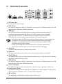
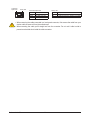
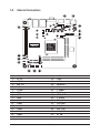
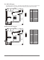
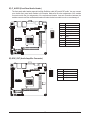
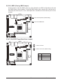
1
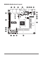
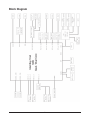
MVBAYAI Intel® Atom® processor motherboard User's Manual Rev. 1001 Copyright © 2014 GIGA-BYTE TECHNOLOGY CO., LTD. All rights reserved. The trademarks mentioned in this manual are legally registered to their respective owners. Disclaimer Information in this manual is protected by copyright laws and is the property of GIGABYTE. Changes to the specifications and features in this manual may be made by GIGABYTE without prior notice. No part of this manual may be reproduced, copied, translated, transmitted, or published in any form or by any means without GIGABYTE's prior written permission. Documentation Classifications In order to assist in the use of this product, GIGABYTE provides the following types of documentations: For detailed product information, carefully read the User's Manual. For product-related information, check on our website at: http://www.gigabyte.com Table of Contents Box Contents....................................................................................................................4 MVBAYAI Motherboard Layout.........................................................................................5 Block Diagram..................................................................................................................8 Chapter 1 Hardware Installation......................................................................................9 1-1 1-2 1-3 Installation Precautions..................................................................................... 9 Product Specifications..................................................................................... 10 Installing the Memory...................................................................................... 12 1-3-1 1-4 1-5 Installing a Memory ................................................................................................12 Back Panel Connectors................................................................................... 13 Internal Connectors......................................................................................... 15 Chapter 2 BIOS Setup...................................................................................................30 2-1 2-2 The Main Menu............................................................................................... 32 Advanced Menu.............................................................................................. 34 2-2-1 2-2-2 2-2-3 2-2-3-1 2-2-4 2-2-5 2-2-6 2-3 2-4 Hardware Monitor ...................................................................................................35 S5 RTC Wake Settings............................................................................................36 CPU Configuration...................................................................................................37 CPU Information......................................................................................................38 SATA Configuration.................................................................................................39 CSM Configuration..................................................................................................40 SIO Configuration....................................................................................................41 Chipset Menu.................................................................................................. 46 Security Menu................................................................................................. 47 2-4-1 Secure Boot menu...................................................................................................48 2-4-1-1 Key Management....................................................................................................49 2-5 2-6 Boot Menu....................................................................................................... 51 Save & Exit Menu............................................................................................ 52 -3- Box Contents Motherboard IO Shield *1 (12AIO-MVBAY0-00R) SATA 2.0 cable 500mm*1 (25CF4-500522-H3S) SATA power cable *1 (25CRI-100B00-H3R) • The box contents above are for reference only and the actual items shall depend on the product package you obtain. The box contents are subject to change without notice. • The motherboard image is for reference only. -4- MVBAYAI Motherboard Layout 1 28 2 3 5 6 7 40 41 34 42 29 30 35 36 37 33 31 43 32 27 26 25 23 22 4 14 16 24 19 17 15 21 20 18 -5- 8 39 38 9 10 11 12 13 Item 1 2 3 AUDIO Code Description Audio connectors RJ45 LAN port (top) / USB 2.0 ports (buttom) RJ45 LAN port (top) / USB 2.0 ports (buttom) Serial port (top) / VGA port (bottom) HDMI port PS/2 Mouse/Keyboard cable connector USB 3.0 port DC In power connector 4 pin main power connector LVDS enable/disable jumper LVDS connector LCD Inverter Connector DDR3 SO-DIMM slot CPU DDR3 SO-DIMM slot Serial port cable connector #5 Serial port cable connector #6 SATA HDD power connector mSATA/extension board connector SATA 3Gb/s connector Front panel header LPC connector USB 2.0 header AT/ATX Power Mode Select jumper GPIO connector Mini PCi Express connector PCI 32bit/33MHz slot Front Panel Audio connector Audio Amplifier connector CPU fan connector Battery cable connector Clear CMOS jumper Systen fan connector COM3 Power Select jumper Serial port cable connector #3 Serial port cable connector #4 Serial port cable connector #1 COM1 Power Select jumper RS232/RS422/RS485 Select Jumper for COM1 USB_LAN1 USB_LAN2 4 5 6 7 8 9 10 11 12 13 14 15 16 17 18 19 20 21 22 23 24 25 26 27 28 29 30 31 32 33 34 35 36 37 38 VGA_COM2 HDMI KB_MS RUSB1 DC_IN ATX_12V JRS6 LVDS BKL_CN SODIMM1 CPU SODIMM2 COM5 COM6 SATAPW_1 M_SATA SATA1 F_PANEL LPC F_USB1 AT_CN GPIO_CNT MIN_PCIE PCI F_AUDIO SKP_OUT CPU_FAN BAT_CN CLR_CMOS SYS_FAN JCOM3 COM3 COM4 COM1 JCOM1 39 JRS3 -6- 40 JRS2 41 JRS4 42 JRS1 43 JP2 RS232/RS422/RS485 Select Jumper for COM1 RS232/RS422/RS485 Select Jumper for COM1 RS232/RS422/RS485 Select Jumper for COM1 LVDS Panel GPIO Control jumper -7- Block Diagram -8- Chapter 1 Hardware Installation 1-1 Installation Precautions The motherboard contains numerous delicate electronic circuits and components which can become damaged as a result of electrostatic discharge (ESD). Prior to installation, carefully read the user's manual and follow these procedures: • Prior to installation, do not remove or break motherboard S/N (Serial Number) sticker or warranty sticker provided by your dealer. These stickers are required for warranty validation. • Always remove the AC power by unplugging the power cord from the power outlet before installing or removing the motherboard or other hardware components. • When connecting hardware components to the internal connectors on the motherboard, make sure they are connected tightly and securely. • When handling the motherboard, avoid touching any metal leads or connectors. • It is best to wear an electrostatic discharge (ESD) wrist strap when handling electronic components such as a motherboard, CPU or memory. If you do not have an ESD wrist strap, keep your hands dry and first touch a metal object to eliminate static electricity. • Prior to installing the motherboard, please have it on top of an antistatic pad or within an electrostatic shielding container. • Before unplugging the power supply cable from the motherboard, make sure the power supply has been turned off. • Before turning on the power, make sure the power supply voltage has been set according to the local voltage standard. • Before using the product, please verify that all cables and power connectors of your hardware components are connected. • To prevent damage to the motherboard, do not allow screws to come in contact with the motherboard circuit or its components. • Make sure there are no leftover screws or metal components placed on the motherboard or within the computer casing. • Do not place the computer system on an uneven surface. • Do not place the computer system in a high-temperature environment. • Turning on the computer power during the installation process can lead to damage to system components as well as physical harm to the user. • If you are uncertain about any installation steps or have a problem related to the use of the product, please consult a certified computer technician. -9- Hardware Installation 1-2 Product Specifications CPU Memory Audio LAN Expansion Slots Onboard Graphics Storage Interface USB Internal Connectors Back Panel Connectors Hardware Installation Support for Intel® Celeron® J1900 (2.0 GHz) processor TDP 10W L1/L2 cache varies with CPU 2 x SO-DIMM slots support 1.35V DDR3L 1333/1600MHz Support up 16GB Realtek® ALC269 codec High Definition Audio 2 channel 2 x Realtek RTL8111G GbE controllers supports 10/100/1000 Mbps 1 x mini PCI 32bit/33MHz slot 1 x Mini PCI Express slot (full size) Build in Intel® Intel® processor 1 x SATA 3Gb/s connector 1 x mSATA socket (full size) Up to 6 USB 2.0 ports (4 on the back panel, 2 via the USB brackets connected to the internal USB headers) 1 x USB 3.0 port 1 x 4 pin ATX 12V power connector 1 x SATA 3Gb/s connector 1 x SATA Power connector 1 x CPU fan header 1 x System fan header 5 x Serial port cable connectors 2 x COM power select headers (JCOM1/JCOM3) 1 x Front panel header 1 x Front Panel Audio header 1 x USB 2.0 header 1 x LVDS connector 1 x Brightness control connector 1 x LPC connector 1 x GPIO connector 1 x Speaker out header 1 x PS/2 Keyboard/Mouse header 1 x PS/2 connector 1 x USB3.0 port 1 x HDMI port 1 x VGA port 1 x Serial port 4 x USB 2.0 ports 2 x RJ-45 port 3 x Audio connectors - 10 - I/O Controller iTE IT8892E chip Hardware Monitor System voltage detection CPU/System temperature detection CPU/System fan speed control *Whether the CPU/system fan speed control function is supported will depend on the CPU/system cooler you install. BIOS AMI BIOS Form Factor Mini ITX Form Factor; 170CM x 170CM GIGABYTE reserves the right to make any changes to the product specifications and product-related information without prior notice. - 11 - Hardware Installation 1-3 Installing the Memory Read the following guidelines before you begin to install the memory: • Make sure that the motherboard supports the memory. It is recommended that memory of the same capacity, brand, speed, and chips be used. • Always turn off the computer and unplug the power cord from the power outlet before installing the memory to prevent hardware damage. • Memory modules have a foolproof design. A memory module can be installed in only one direction. If you are unable to insert the memory, switch the direction. 1-3-1 Installing a Memory Installation Step: Step 1. Align the memory with the SO-DIMM module and insert the SO-DIMM memory module into the SO-DIMM slot. Please note that memory module has a foolproof insertion design. A memory module can be installed In only one direction. Step 2. Push the memory and seat it firmly. Step 3. Reverse the installation steps when you wish to remove the SO-DIMM module. 1 2 Hardware Installation - 12 - 1-4 Back Panel Connectors DC Power Jack Connect the DC power to this port. USB 3.0 Port The USB port supports the USB 3.0 specification. Use this port for USB devices such as a USB keyboard/mouse, USB printer, USB flash drive and etc. HDMI Port The HDMI (High-Definition Multimedia Interface) provides an all-digital audio/video interface to transmit the uncompressed audio/video signals and is HDCP compliant. Connect the HDMI audio/video device to this port. The HDMI Technology can support a maximum resolution of 1920x1080p but the actual resolutions supported depend on the monitor being used. • When After installing the HDMI device, make sure the default device for sound playback is the HDMI device. (The item name may differ by operating system. Refer the figures below for details.), and enter BIOS Setup, then set Onboard VGA output connect to D-SUB/ HDMI under Advanced BIOS Features.. • Please note the HDMI audio output only supports AC3, DTS and 2-channel-LPCM formats. (AC3 and DTS require the use of an external decoder for decoding.) Serial Port Connects to serial-based mouse or data processing devices. Video Port The video in port allows connect to video in, which can also apply to video loop thru function. RJ-45 LAN Port The Gigabit Ethernet LAN port provides Internet connection at up to 1 Gbps data rate. The following describes the states of the LAN port LEDs. USB 2.0 Port The USB port supports the USB 2.0 specification. Use this port for USB devices such as a USB keyboard/mouse, USB printer, USB flash drive and etc. Line In Jack (Blue) The default line in jack. Use this audio jack for line in devices such as an optical drive, walkman, etc. Line Out Jack (Green) The default line out jack. Use this audio jack for a headphone or 2-channel speaker. This jack can be used to connect front speakers in a 4/5.1/7.1-channel audio configuration. MIC In (Pink) The default MIC In jack. Microphone cab be connected to MIC In jack. - 13 - Hardware Installation Connection/ Speed LED Activity LED LAN Port Connection/Speed LED: State Orange Green Off Activity LED: Description 1 Gbps data rate 100 Mbps data rate 10 Mbps data rate State Description Blinking Data transmission or receiving is occurring Off No data transmission or receiving is occurring • When removing the cable connected to a back panel connector, first remove the cable from your device and then remove it from the motherboard. • When removing the cable, pull it straight out from the connector. Do not rock it side to side to prevent an electrical short inside the cable connector. Hardware Installation - 14 - 1-5 Internal Connectors 3 25 26 12 10 28 16 30 24 23 21 31 8 11 13 5 27 29 9 2 7 6 1 18 17 4 14 15 22 19 20 1) 2) 3) 4) 5) 6) 7) 8) 9) 10) 11) 12) 13) 14) 15) 16) ATX_12V DC_IN KB_MS BKL_CN COM1 JCOM1 JRS3 JRS2 JRS4 JRS1 COM3 JCOM3 COM4 COM5 COM6 JP2 17) 18) 19) 20) 21) 22) 23) 24) 25) 26) 27) 28) 29) 30) 31) - 15 - LVDS JRS6 SATA1 SATAPW_1 LPC F_PANEL F_USB1 GPIO_CNT F_AUDIO SPK_OUT CPU_FAN SYS_FAN BAT_CON CLR_CMOS AT_CN Hardware Installation Read the following guidelines before connecting external devices: • First make sure your devices are compliant with the connectors you wish to connect. • Before installing the devices, be sure to turn off the devices and your computer. Unplug the power cord from the power outlet to prevent damage to the devices. • After installing the device and before turning on the computer, make sure the device cable has been securely attached to the connector on the motherboard. Hardware Installation - 16 - ATX 1) ATX_12V (2x4 12V Power Connector) With the use of the power connector, the power supply can supply enough stable power to all the components on the motherboard. Before connecting the power connector, first make sure the power supply is turned off and all devices are properly installed. The power connector possesses a foolproof design. Connect the power supply cable to the power connector in the correct orientation. The 12V power connector mainly supplies power to the CPU. If the 12V power connector is not connected, the computer will not start. To meet expansion requirements, it is recommended that a power supply that can withstand high power consumption be used (500W or greater). If a power supply is used that does not provide the required power, the result can lead to an unstable or unbootable system. ATX_12V ATX_12V 4 2 3 1 Pin No. 1 2 3 4 Definition GND GND +12V +12V FDD 2) DC_IN (SC In Power Connector) GND (Pin 1 & 2) VIN (Pin 3 & 4) IDE - 17 - Pin No. 1 2 3 4 5 6 7 8 9 Definition GND GND VIN_IN VIN_IN GND GND GND GND GND Hardware Installation 3) KB_MS (PS/2 Mouse/Keyboard cable connector) 6 1 Pin No. 1 2 3 4 5 6 Definition PS POWER MCLK MDATA KCLK KDATA GND 4) BKL_CN (LCD Inverter Connector) 1 Pin No. 1 2 3 4 5 42 41 Hardware Installation - 18 - 5 Definition VCC BLKCTL ENABKL GND +12V 5) COM1 (Serial Port 1 Cable Connector)/JRS3/JRS2/JRS4/JRS1 6) JCOM1 (COM1 Select RS232/422/485 Jumper) 7/8/9/10) RS232/RS422/RS485 Select Jumpers for COM1) The COM header can provide one serial port via an optional COM port cable. For purchasing the optional COM port cable, please contact the local dealer. JRS4 JRS1 JRS2 JRS3 1 9 2 10 JCOM1 Pin No. 1 2 3 4 5 6 7 8 9 10 COM1 Definition NRXD1_DNDCD1_DNDTR1_DNTXD1_DNDSR1GND NCTS1NRTS1NC NRI1- JRS1/JRS2/JRS3/JRS4: 1 1-2 Close: RS422/RS485 1 2-3 Close: RS232 (Default setting) JCOM1: 1 5 2 6 1 5 2 6 1 5 2 6 1-2 Close: RS232 Pin No. 1 2 3 4 5 6 3-4 Close: RS422 Definition RXD232 RXD1 RXD422 RXD1 RXD485 RXD1 5-6 Close: RS485 - 19 - Hardware Installation 11/12) COM3/COM4 (Serial Port 3/4 Cable Connectors) COM3/COM4 COM4 COM3 COM3 Pin No. 1 2 3 4 5 6 7 8 9 10 1 9 2 10 COM4 Definition NRXD3NDCD3NDTR3NTXD3NDSR3GND NCTS3NRTS3NC RI3-/1.5V/12V Pin No. 1 2 3 4 5 6 7 8 9 10 Definition NRXD4NDCD4NDTR4NTXD4NDSR4GND NCTS4NRTS4NC NRI4- 13) JCOM3 (5V/12V/RI Signal Select Header for Serial Port 3) Pin No. 1 2 3 4 5 6 JCOM3 Hardware Installation - 20 - Definition +5V GND NRI3-(RI#) GND +12V GND 2 1 6 5 1-2 Close: 5V (Power COM) 2 1 6 5 3-4 Close: RI (STAND COM) 2 1 6 5 5-6 Close: 12V (Power COM) 14/15) COM5/COM6 (Serial Port 5/6 Cable Connectors) COM5/COM6 COM5 COM6 COM5 Pin No. 1 2 3 4 5 6 7 8 9 10 9 10 1 2 COM6 Definition NRXD5NDCD5NDTR5NTXD5NDSR5GND NCTS5NRTS5NC NRI5- Pin No. 1 2 3 4 5 6 7 8 9 10 Definition NRXD6NDCD6NDTR6NTXD6NDSR6GND NCTS6NRTS6NC NRI6- 16) JP2 (LVDS Panel GPIO 1 &2 Control Jumper ) 01 10 1 2 5 6 1 2 5 6 Pin No. 1 2 3 4 5 6 - 21 - Default For 1024*768 -- For 1024*600 Definition VCC3 VCC3 GPIO_1 GPIO_2 GND GND Hardware Installation 17) LVDS (LVDS Connector) LVDS stands for Low-voltage differential signaling, which uses high-speed analog circuit techniques to provide multigigabit data transfers on copper interconnects and is a generic interface standard for high-speed data transmission. Pin No. 1 2 3 4 5 6 7 8 9 10 11 12 13 14 15 16 17 18 19 20 Hardware Installation Definition VCC3 VCC VCC3 VCC SPC0 SPD0 GND GND A1P_C A0P_C A1M_C A0M_C GND GND A3P_C A2P_C A3M_C A2M_C GND GND Pin No. 21 22 23 24 25 26 27 28 29 30 31 32 33 34 35 36 37 38 39 40 - 22 - 1 39 2 40 Definition A5P_C A4P_C A5M_C A4M_C GND GND A7P_C A6P_C A7M_C A6M_C GND GND CLK2P_C CLK1P_C CLK2M_C CLK1M_C GND NC +12V +12V 18) JRS6 (LVDS Enable/Disable Jumper) 1 1-2 Close: Enable LVDS funciton. (Default setting) 1 2-3 Close: Disable LVDS funciton. Pin No. 1 2 3 Definition DDI1_HPD HPDET_C NC DEBUG PORT 19) SATA1 (SATA 3Gb/s Connector) The SATA connectors conform to SATA 3Gb/s standard and are compatible with 1.5Gb/s standard. Each SATA connector supports a single SATA device. 1 Pin No. 1 2 3 4 5 6 7 8 9 - 23 - 9 Definition GND TXP TXN GND RXN RXP GND VCC GND Hardware Installation 20) SATAPW_1 (SATA HDD Power Connector) 4 Pin No. 1 2 3 4 1 Definition +12V GND GND VCC 21) LPC (Low Pin Connector) 13 14 1 Hardware Installation - 24 - 2 Pin No. 1 2 3 4 5 6 7 8 9 10 11 12 13 14 Definition LAD0 +3.3V LAD1 -PLTRST2_N LAD2 -LFRAME LAD3 LPC25 SERIRQ_N GND +5V GND +5V GND 22) F_PANEL (Front Panel Header) Connect the power switch, reset switch, speaker, and system status indicator on the chassis to this header according to the pin assignments below. Note the positive and negative pins before connecting the cables. Pin No. 1 2 3 4 5 6 7 8 9 10 Signal Name HD+ MPD+ HD- GND GND PW+ RST+ GND NC NC 2 10 1 9 Definition Hard Disk LED Signal anode (+) Power LED Signal anode (+) Hard Disk LED Signal cathode(-) Ground Ground Power Button anode (+) Reset Button Ground No connect No Pin The front panel design may differ by chassis. A front panel module mainly consists of power switch, reset switch, power LED, hard drive activity LED, and etc. When connecting your chassis front panel module to this header, make sure the wire assignments and the pin assignments are matched correctly. - 25 Hardware Installation 23) F_USB1 (USB Header) The headers conform to USB 2.0/1.1 specification. Each USB header can provide two USB ports via an optional USB bracket. For purchasing the optional USB bracket, please contact the local dealer. 2 1 10 9 Pin No. 1 2 3 4 5 6 7 8 9 10 Definition Power (5V) Power (5V) -FUSBP2 -FUSBP3 +FUSBP2 +FUSBP3 GND GND GND GND 24) GPIO_CNT (GPIO connector) 11 12 1 Hardware Installation - 26 - 2 Pin No. 1 2 3 4 5 6 7 8 9 10 11 12 Definition SOGPO_1 SOGPI_1 SOGPO_2 SOGPI_2 SOGPO_3 SOGPI_3 SOGPO_4 SOGPI_4 SMCLK_N SMDATA_N +5V GND 25) F_AUDIO (Front Panel Audio Header) The front panel audio header supports Intel High Definition audio (HD) and AC'97 audio. You may connect your chassis front panel audio module to this header. Make sure the wire assignments of the module connector match the pin assignments of the motherboard header. Incorrect connection between the module connector and the motherboard header will make the device unable to work or even damage it. 2 1 10 9 Pin No. 1 2 3 4 5 6 7 8 9 10 Definition MIC_L GND MIC_R -ACZ_DET HPOUT_R GND FAUDIO_J NC HPOUT_L GND 26) SPK_OUT (Audio Amplifier Connector) 1 4 - 27 - Pin No. 1 2 3 4 Definition OUT_R+ OUT_ROUT_LOUT_L+ Hardware Installation 27/28) CPU_FAN/SYS_FAN (CPU Fan/System Fan Headers) The motherboard has one 4-pin CPU fan header (CPU_FAN), and one 4-pin (SYS_FAN) system fan headers. Most fan headers possess a foolproof insertion design. When connecting a fan cable, be sure to connect it in the correct orientation (the black connector wire is the ground wire). The motherboard supports CPU fan speed control, which requires the use of a CPU fan with fan speed control design. For optimum heat dissipation, it is recommended that a system fan be installed inside the chassis. CPU_FAN CPU_FAN SYS_FAN 1 SYS_FAN 4 1 4 Pin No. 1 2 3 4 Definition GND +12V Sense Speed Control • Be sure to connect fan cables to the fan headers to prevent your CPU and system from overheating. Overheating may result in damage to the CPU or the system may hang. • These fan headers are not configuration jumper blocks. Do not place a jumper cap on the headers. 29) BATTERY (Battery Scoket) The battery provides power to keep the values (such as BIOS configurations, date, and time information) in the CMOS when the computer is turned off. Replace the battery when the battery voltage drops to a low level, or the CMOS values may not be accurate or may be lost. 1 2 Pin No. Definition 1 RTC Reset 2 GND • Always turn off your computer and unplug the power cord before replacing the battery. • Replace the battery with an equivalent one. Danger of explosion if the battery is replaced with an incorrect model. • Contact the place of purchase or local dealer if you are not able to replace the battery by yourself or uncertain about the battery model. • Used batteries must be handled in accordance with local environmental regulations. Hardware Installation - 28 - 30) CLR_CMOS (Clearing CMOS Jumper) Use this jumper to clear the CMOS values (e.g. date information and BIOS configurations) and reset the CMOS values to factory defaults. To clear the CMOS values, place a jumper cap on the two pins to temporarily short the two pins or use a metal object like a screwdriver to touch the two pins for a few seconds. Open: Normal operation (Default setting) Close: Clear CMOS data 31) AT_CN (AT/ATX Power Mode Select Jumper) 1 1 1-2 Close: AT mode. 2-3 Close: ATX mode. (Default setting) Pin No. 1 2 3 - 29 - Definition TXD5_AT MODE TXD5 TXD5_AT Hardware Installation Chapter 2 BIOS Setup BIOS (Basic Input and Output System) records hardware parameters of the system in the CMOS on the motherboard. Its major functions include conducting the Power-On Self-Test (POST) during system startup, saving system parameters and loading operating system, etc. BIOS includes a BIOS Setup program that allows the user to modify basic system configuration settings or to activate certain system features. When the power is turned off, the battery on the motherboard supplies the necessary power to the CMOS to keep the configuration values in the CMOS. To access the BIOS Setup program, press the <DEL> key during the POST when the power is turned on. • BIOS flashing is potentially risky, if you do not encounter problems of using the current BIOS version, it is recommended that you don't flash the BIOS. To flash the BIOS, do it with caution. Inadequate BIOS flashing may result in system malfunction. • It is recommended that you not alter the default settings (unless you need to) to prevent system instability or other unexpected results. Inadequately altering the settings may result in system's failure to boot. If this occurs, try to clear the CMOS values and reset the board to default values. (Refer to the "Restore Defaults" section in this chapter or introductions of the battery/clearing CMOS jumper in Chapter 1 for how to clear the CMOS values.) BIOS Setup Program Function Keys <h><i> Move the selection bar to select an item <f><g> Move the selection bar to select the screen <Enter> Execute command or enter the submenu <Esc> Main Menu: Exit the BIOS Setup program Submenus: Exit current submenu <+> Increase the numeric value or make changes <-> Decrease the numeric value or make changes <F1>General Help <F2> Restore the previous BIOS settings for the current submenus <F3> Load the Optimized BIOS default settings for the current submenus <F4> Save all the changes and exit the BIOS Setup program BIOS Setup - 30 - Main This setup page includes all the items in standard compatible BIOS Advanced This setup page includes all the items of AMI BIOS special enhanced features. (ex: Auto detect fan and temperature status, automatically configure hard disk parameters.) Chipset Northbridge and Southbridge additional features configuration. Boot This setup page provides items for configuration of boot sequence. Security Change, set, or disable supervisor and user password. Configuration supervisor password allows you to restrict access to the system and BIOS Setup. A supervisor password allows you to make changes in BIOS Setup. A user password only allows you to view the BIOS settings but not to make changes. Save & Exit Save all the changes made in the BIOS Setup program to the CMOS and exit BIOS Setup. Abandon all changes and the previous settings remain in effect. Pressing <Y> to the confirmation message will exit BIOS Setup. (Pressing <Esc> can also carry out this task.) - 31 - BIOS Setup 2-1 The Main Menu Once you enter the BIOS Setup program, the Main Menu (as shown below) appears on the screen. Use arrow keys to move among the items and press <Enter> to accept or enter other sub-menu. Main Menu Help The on-screen description of a highlighted setup option is displayed on the bottom line of the Main Menu. Submenu Help While in a submenu, press <F1> to display a help screen (General Help) of function keys available for the menu. Press <Esc> to exit the help screen. Help for each item is in the Item Help block on the right side of the submenu. • When the system is not stable as usual, select the Restore Defaults item to set your system to its defaults. • The BIOS Setup menus described in this chapter are for reference only and may differ by BIOS version. BIOS Setup - 32 - BIOS Information Project Name Display name of the project. BIOS Version Display version number of the BIOS. BIOS Build Date and Time Displays the date and time when the BIOS setup utility was created. LAN1/2 MAC Address Displays the LAN1 and LAN2 MAC address information. Memory Information Total Memory Display the total memory size of the installed memory. TXE FW Version Display the TXE firmware version. System Date Set the date following the weekday-month-day- year format. System Time Set the system time following the hour-minute- second format. - 33 - BIOS Setup 2-2 Advanced Menu The Advanced menu display submenu options for configuring the function of various hardware components. Select a submenu item, then press Enter to access the related submenu screen. BIOS Setup - 34 - 2-2-1 Hardware Monitor Press Enter to view the Hardware Monitor screen which displays a real-time record of the CPU/system temperature, and fan speed, Items on this window are non-configurable. PC Health Status CPU/System SMART FAN Function Enable CPU/System Fan Stop Warning function. Option available: Enabled/Disabled. Default setting is Enabled. CPU/System FAN Fail Detect Enable/Disable CPU/System FAN Fail Detect function. Option available: Enabled/Disabled. Default setting for CPU FAN Fail Detect is Enabled. Default setting for System FAN Fail Detect is Disabled. CPU Temperature/System Temperature Displays current CPU and System temperature. CPU/System Fan Speed (RPM) Displays current CPU and system fan speed. VCORE/DDR1.35/+12V/VCC/VCC3 Displays current CPU and system voltage status. - 35 - BIOS Setup 2-2-2 S5 RTC Wake Settings Wake system from S5 Enable or disable System wake on alarm event. When enabled, System will wake on the hr:min:sec specified. Default setting is Disabled. Wake up hour(Note) Press <+> and <-> to define the wake up hour. Wake up minute(Note) Press <+> and <-> to define the wake up minute. Wake up second(Note) Press <+> and <-> to define the wake up second. (Note) This item appears when Wake system from S5 is set to Fixed time. BIOS Setup - 36 - 2-2-3 CPU Configuration CPU Information Press [Enter] to view the installed CPUinformation. Intel Virtualization Technology Select whether to enable the Intel Virtualization Technology function. VT allows a single platform to run multiple operating systems in independent partitions. Options available: Enabled/Disabled. Default setting is Enabled. EIST (Enhanced Intel SpeedStep Technology) Conventional Intel SpeedStep Technology switches both voltage and frequency in tandem between high and low levels in response to processor load. Options available: Enabled/Disabled. Default setting is Enabled. Turbo Mode When this feature is enabled, the processor can dynamically overclock one or two of its four processing cores to improve performance with applications that are not multi-threaded or optimized for quad-core processors. Options available: Enabled/Disabled. Default setting is Enabled. CPU C State Report Enable/Disable CPU C State report function. Options available: Enabled/Disabled. Default setting is Enabled. - 37 - BIOS Setup 2-2-3-1CPU Information CPU Type/Signature/Processor Cores/64-bit/Intel HT Technology/ Intel VT-x Technology Displays the technical specifications for the installed processor. Cache Information L1 Data Cache / L1 Code Cache / L2 Cache / L3 Cache Displays the technical specifications for the installed processor. BIOS Setup - 38 - 2-2-4 SATA Configuration SATA Mode Selection Select the on chip SATA type. IDE Mode: When set to IDE, the SATA controller disables its AHCI function and runs in the IDE emulation mode. AHCI Mode: When set to AHCI, the SATA controller enables its AHCI functionality. Options available: IDE/AHCI. Default setting is AHCI Mode. Serial ATA Port 1/mSATA Port The category identifies Serial ATA and mSATA types of hard disk that are installed in the computer. System will automatically detect HDD type. Note that the specifications of your drive must match with the drive table. The hard disk will not work properly if you enter improper information for this category. Hard drive information should be labeled on the outside device casing. Enter the appropriate option based on this information. - 39 - BIOS Setup 2-2-5 CSM Configuration Compatibility Support Module Configuration Press Enter to configure the advanced items. CSM Support Enable/Disable Compatibility Support Module (CSM) support function. Options available: Enabled/Disabled. Default setting is Disabled. • The following five items appears and configurable when the Launch CSM is set to Enabled. • If the Launch CSM is set to Disabled, the following five items will not be able to support Legacy mode. Network stack Enable/Disable UEFI network stack. Options available: Enabled/DIsabled. Default setting is Disabled. Video Controls the execution UEFI and Legacy Video OpROM. Options available: UEFI/Legacy/Do not launch. Default setting is UEFI only. BIOS Setup - 40 - 2-2-6 SIO Configuration - 41 - BIOS Setup BIOS Setup - 42 - - 43 - BIOS Setup AMI SIO Driver Version Display the AMI SIO driver version information. Super IO Chip Logical Device(s) Configuration [*Active*] Serial Port 1/2/3/4/5/6 Press [Enter] for confuguration of advanced items. Serial Port 1 Configuration Use This Device When enabled allows you to configure the serial port 1 settings. When set to Disabled, displays no configuration for the serial port. Options available: Enabled/Disabled. Default setting is Enabled. Logical Device Settings Display the Serial Port 1 base I/O addressand IRQ. Serial Port 2 Configuration Use This Device When enabled allows you to configure the serial port 2 settings. When set to Disabled, displays no configuration for the serial port. Options available: Enabled/Disabled. Default setting is Enabled. Logical Device Settings Display the Serial Port 2 base I/O addressand IRQ. Serial Port 3 Configuration Use This Device When enabled allows you to configure the serial port 3 settings. When set to Disabled, displays no BIOS Setup - 44 - configuration for the serial port. Options available: Enabled/Disabled. Default setting is Enabled. Logical Device Settings Display the Serial Port 3 base I/O addressand IRQ. Serial Port 4 Configuration Use This Device When enabled allows you to configure the serial port 4 settings. When set to Disabled, displays no configuration for the serial port. Options available: Enabled/Disabled. Default setting is Enabled. Logical Device Settings Display the Serial Port 4 base I/O addressand IRQ. Serial Port 5 Configuration Use This Device When enabled allows you to configure the serial port 5 settings. When set to Disabled, displays no configuration for the serial port. Options available: Enabled/Disabled. Default setting is Enabled. Logical Device Settings Display the Serial Port 5 base I/O addressand IRQ. Serial Port 6 Configuration Use This Device When enabled allows you to configure the serial port 6 settings. When set to Disabled, displays no configuration for the serial port. Options available: Enabled/Disabled. Default setting is Enabled. Logical Device Settings Display the Serial Port 6 base I/O addressand IRQ. - 45 - BIOS Setup 2-3 Chipset Menu Onboard LAN1/2 Enable/Disable onboard LAN controller. Options available: Enabled/Disabled. Default setting is Enabled. Onboard Audio Enable/Disable onboard audio controller. Options available: Enabled/Disabled. Default setting is Enabled. Restore AC Power Loss This option provides user to set the mode of operation if an AC / power loss occurs. Power On: System power state when AC cord is re-plugged. Power Off: Do not power on system when AC power is back. Last State: Set system to the last sate when AC power is removed. Options available: Power On/Power Off/Last State. Default setting is Power Off. Erp Mode Enable/Disable Erp support function. Options available: Enabled/Disabled. Default setting is Disabled. Backlight brightness Configure the backlight brightness. Options available: 5%/25%/50%/75%/100%. Default setting is 100%. BIOS Setup - 46 - 2-4 Security Menu The Security menu allows you to safeguard and protect the system from unauthorized use by setting up access passwords. There are two types of passwords that you can set: • Adminstrator Password Entering this password will allow the user to access and change all settings in the Setup Utility. • User Password Entering this password will restrict a user’s access to the Setup menus. To enable or disable this field, a Administrator Password must first be set. A user can only access and modify the System Time, System Date, and Set User Password fields. AdministratorPassword Press Enter to configure the Administrator password. User Password Press Enter to configure the user password. Secure Boot menu Press [Enter] for configuration of advanced items. - 47 - BIOS Setup 2-4-1 Secure Boot menu System Mode Display the System Mode state. Secure Boot Display the System Mode State. Secure Boot Secure Boot requires all the applications that are running during the booting process to be pre-signed with valid digital certificates. This way, the system knows all the files being loaded before Windows 8 loads and gets to the login screen have not been tampered with. Options available: Enabled/Disabled. Default setting is Disabled. Secure Boot Mode(Note) Define the Secure Boot Mode. Set this item to Custom to advanced items configuration. Option available: Standard/Custom. Default setting is Custom. Key Management Press Enter to configure the advanced items. (Note) Advanced items prompt when this item is set to Cutom. BIOS Setup - 48 - 2-4-1-1Key Management Key Management This item appears only when the Secure Boot Mode is set to Custom. Default Key Provisioning Force the system to Setup Mode. This will clear all Secure Boot Variables such as Platform Key (PK), Key-exchange Key (KEK), Authorized Signature Database (db), and Forbidden Signaures Database (dbx). Options available: Enabled/Disabled. Default setting is Disabled. Enroll All Factory Default Keys Press [Enter] to install all factory default keys. Save All Secure Boot Variables Press [Enter] to save all Secure Boot Variables. Platform Key (PK) Display the status of Platform Key. Delete the PK Press [Enter] to delete the existed PK. Once the PK is deleted, all the system's Secure Boot keys will not be activated. Set new PK File Press [Enter] to configure a new PK. Key Exchange Key Database (KEK) Display the status of Platform Key. Delete KEK Press [Enter] to delete the KEK from your system. - 49 - BIOS Setup Set new KEK Press [Enter] to configure a new KEK. Append Var to KEK Press [Enter] to load additional KEK from a storage devices for an additional db and dbx management. Authorized Signature Database (DB) Display the status of Authorized Signature Database. Delete DB Press [Enter] to delete the db from your system. Set new DB Press [Enter] to configure a new db. Append aVar to DB Press [Enter] to load additional db from a storage devices. Forbidden Signature Database (DBX) Display the status of Forbidden Signature Database. Delete the DBX Press [Enter] to delete the dbx from your system. Set DBX from File Press [Enter] to configure a new dbx. Append Var to DBX Press [Enter] to load additional db from a storage devices. BIOS Setup - 50 - 2-5 Boot Menu The Boot menu allows you to set the drive priority during system boot-up. BIOS setup will display an error message if the drive(s) specified is not bootable. Boot Configuration Quiet Boot Enables or disables showing the logo during POST. Options available: Enabled/Disabled. Default setting is Disabled. Fast Boot This BIOS feature alows you to decrease the time it takes to boot up the system by skipping certain booting procedures. Options available: Enabled/Disabled. Default setting is Disabled. Boot Option Priorities Boot Option #1/#2 Press Enter to configure the boot priority. By default, the server searches for boot devices in the following secquence: 1. UEFI device. 2. Hard drive. - 51 - BIOS Setup 2-6 Save & Exit Menu The Exit menu displays the various options to quit from the BIOS setup. Highlight any of the exit options then press Enter. Save Changes and Reset Saves changes made and close the BIOS setup. Options available: Yes/No. Discard Changes and Reset Discards changes made and close the BIOS setup. Options available: Yes/No. Restore Defaults Loads the default settings for all BIOS setup parameters. Setup Defaults are quite demanding in terms of resources consumption. If you are using low-speed memory chips or other kinds of low-performance components and you choose to load these settings, the system might not function properly. Options available: Yes/No. Boot Override Press Enter to configure the device as the boot-up drive. UEFI: Built-in in EFI Shell Press <Enter> on this item to Launch EFI Shell from filesystem device. BIOS Setup - 52 -