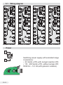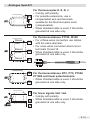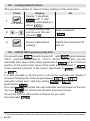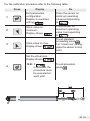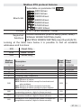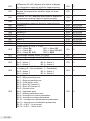
1
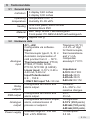
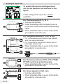
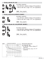
ATR 401
• Regolatore
• Controller
Manuale Installatore
User manual
Summary
1 Introduction
2 Model Identification
3 Technical data
3.1 General data
3.2 Hardware data
3.3 Software data
4 Dimensions and Installation
4.1 Electronics Removal
5 Electrical wirings
5.1 Wiring diagram
6 Display and Key Functions
6.1 Numeric Indicators (Display)
6.2 Meaning of Status Lights (Led)
6.3 Keys
7 Dual input mode
7.1 Selection of process value related to the command output and to the alarms
7.2 Remote setpoint
8 Controller Functions
8.1 Modifying Main Setpoint and Alarm Setpoint Values
8.2 Auto-Tuning
8.3 Manual Tuning
8.4 Automatic Tuning
8.5 Automatic / Manual Regulation for % Output Control
8.6 Soft-Start
8.7 Memory Card (optional)
8.8 Loading default values
8.9 LATCH ON Functions (only AI1)
8.10 Heating-Cooling P.I.D.
9 Serial Communication
10 Configuration
10.1 Modify Configuration Parameter
11 Table of Configuration Parameters
12 Alarm Intervention Modes
13 Table of Anomaly Signals
14 Configuration EASY-UP
15 Summary of Configuration parameters
Page
4
4
5
5
5
6
6
7
7
8
15
15
15
16
17
17
18
19
19
19
19
19
20
20
21
22
22
24
26
30
30
31
49
53
54
55
Pay attention at the section marked with this symbol
Presta attenzione alla sezione contrassegnata da questo simbolo
Sommario
1 Introduzione
2 Identificazione di modello
3 Dati tecnici
3.1 Caratteristiche generali
3.2 Caratteristiche Hardware
3.3 Caratteristiche Software
4 Dimensioni e installazioni
4.1 Estrazione dell’elettronica
5 Collegamenti elettrici
5.1 Schema di collegamento
6 Funzione dei visualizzatori e tasti
6.1 Indicatori numerici (Display)
6.2 Significato delle spie di stato (Led)
6.3 Tasti
7 Modalità doppio ingresso
7.1 Selezione grandezza correlata al comando e agli allarmi
7.2 Setpoint remoto
8 Funzioni del regolatore
8.1 Modifica valore setpoint principale e setpoint di allarme
8.2 Auto-Tuning
8.3 Lancio del Tuning Manuale
8.4 Tuning Automatico
8.5 Regolazione automatico / manuale del controllo % uscita
8.6 Soft-Star
8.7 Memory Card (opzionale)
8.8 Caricamento valori di default
8.9 Funzione LATCH ON (solo AI1)
8.10 Funzionamento da doppia azione (caldo-freddo)
9 Comunicazione Seriale
10 Configurazione
10.1 Modifica parametro di configurazione
11 Tabella parametri di configurazione
12 Modi di intervento allarme
13 Tabella segnalazioni anomalie
14 Configurazione EASY-UP
15 Promemoria configurazione
Sommaire
1 Identification du modèle
2 Données techniques
2.1 Caractéristiques générales
2.2 Caractéristiques Hardware
2.3 Caractéristiques Software
3 Dimensions et Installation
3.1 Déplacement de l’électronique
4 Raccordements électriques
4.1 Schéma des connexions
Pag
59
59
60
60
60
61
61
62
62
63
70
70
70
71
72
72
73
74
74
74
74
74
75
75
76
77
77
79
81
85
85
86
104
108
109
110
114
114
114
115
116
116
117
118
118
1
Introduction
Thanks for choosing a Pixsys controller.
With ATR401 model, Pixsys integrates in a single device all options for
sensors reading and actuators control, beside an useful supply with
extended range 24…230 Vac/Vdc. Thanks to dual universal analogue
input outputs configurable as relay or SSR, the user or the retailer can
reduce stock needs.
The series includes also a model with serial communication RS485
Modbus Rtu and linear output 0-10 V, 0/4-20 mA. The possibility to
repeat parameterization is simplified by the Memory Cards with internal
battery that do not require power supply for the controller.
2
Model Identification
ATR401 series includes four versions.
Looking at the following table it is possible to find the required model.
Power supply 24…230 Vac/Vdc +/-15% 50/60 Hz – 5,5 VA
ATR401-22ABC
2 Analogue inputs + 2 Relays 8 A + 1 SSR
ATR401-23ABC
2 Analogue inputs + 3 Relays 8 A + 1 SSR
ATR401-24ABC
2 Analogue inputs + 4 Relays 8 A + 1 SSR
ATR401-22ABC-T
2 Analogue inputs + 2 Relays 8 A + 1 SSR
1 Output V / mA + RS485
EN 4
3
Technical data
3.1
General data
4 display 0,40 inches
Indicators
4 display 0,30 inches
Operating Temperature 0-45 °C
temperature Humidity 35..95 uR%
IP54 front panel, box IP30 and
Sealing
terminal block IP20
Box: Noryl UL94V1 self-exstinguish
Material
Front panel: PC ABS UL94V0 self-exstinguish
Weight Approx 350 g
3.2
Hardware data
AI1 – AI2:
Configurable via software.
Input:
Thermocouple type K, S, R, J.
Automatic compensation of
cold junction from 0 … 50°C.
Analogue Thermoresistances: PT100,
input PT500, PT1000, Ni100,
PTC1K, NTC10K (β 3435K)
Linear input: 0-10 V, 0-20 o
4-20 mA, 0-40 mV.
Input Potentiometer:
6 K , 150 K .
• ONLY AI2 input T.A.: 50 mA.
Relay Configurable as control and
alarm output.
outputs
SSR output
Analogue
output
Power supply
Configurable as control and
alarm output.
Configurable as control output,
alarm, retransmission of
process or setpoint.
Extended range 24…230 Vac/
Vdc ±15% 50/60 Hz.
Tolerance (25 °C)
+/-0.2% ±1 digit
for thermocouple,
thermoresistance
and V / mA.
Cold junction
accuracy 0.1 °C/°C.
Impedance:
0-10 V: Ri>110 K
0-20 mA: Ri<5
4-20 mA: Ri<5
0-40 mV: Ri>1 M
Contacts:
8 A - 250 V~ for
resistive charges.
24 V;
25 mA.
Configurable:
0-10 V (9500 points);
0-20 mA (7500 points);
4-20 mA (6000 points).
Consumption:
5.5 VA.
5 EN
3.3 Software data
Regulation ON - OFF with hysteresis.
algorithms P, P.I., P.I.D., P.D. proportional time.
Proportional
0...9999 °C o °F
band
0,0...999,9 sec. (0 excludes integral function)
Integral time
Derivative time
0,0...999,9 sec. (0 excludes derivative function)
Controller
functions
Manual or automatic tuning, selectable alarms,
protection of control and alarm setpoints.
4
Dimensions and Installation
42mm
inserimento / insert
Memory Card
MEMORY C.121
Dima di foratura
46 x 91 mm
Frontal panel cut-out
Memory Card (optional)
with battery
Cod. MEMORY C243
Memory Card (optional)
Cod. MEMORY C241
PIXSYS
1
CN1
6
U1
C1
6
CN1
1
ATR401
A3
MAN
TUN
REM
96 mm
C1
C2
A1
A2
PRGM
FNC
SET
PIXSYS
48 mm
112 mm
11
Memory Card
6
1
Spessore suggerito / Suggested thickness
2÷8 mm
EN 6
4.1
Electronics Removal
To configure internal Jumper, remove the electronics by twist off the
screw on instrument frontal side.
Disconnect the device from the mains
before starting to configurate or service it.
WARNING
5
Electrical wirings
Although this controller has been designed to resist
noises in an industrial environments, please notice
the following safety guidelines:
WA R N I N G
• Separate control lines from the power wires.
• Avoid the proximity of remote control switches,
electromagnetic meters, powerful engines.
• Avoid the proximity of power groups, especially
those with phase control.
7 EN
Wiring diagram
Q1
8A
230V
1/2HP
3
3
14
Q2
8A
230V
1/2HP
6
7
4
15
TA
5
2
13
AI2 V TC
mA
4
11
1
5
16
6
+24V
17
7
SSR
AI1 V TC
mA
SUPPLY
12
24...230
Vac/dc
Q1
8A
230V
1/2HP
14
5
16
6
+24V
17
7
SSR
9
0V
20
10
10
ATR401-22ABC
Q1
8A
230V
1/2HP
Q3
8A
230V 0V
1/2HP
19
9
20
ATR401-23ABC
2
13
3
14
AI2 V TC
mA
Q2
8A
230V
1/2HP
11
1
AI1 V TC
mA
SUPPLY
12
24...230
Vac/dc
Q1
8A
230V
1/2HP
15
5
16
6
+24V
17
Q2
8A
230V
1/2HP
7
SSR
10
Q3
8A
DI
230V (PnP)
1/2HP
Q4
0V
8A
230V
1/2HP
13
14
AI2 V TC
mA
4
15
16
+24V
17
SSR
18
8
DI
(PnP)
19
9
AI1 V TC
mA
SUPPLY
12
24...230
Vac/dc
18
8
DI
(PnP)
4
15
18
8
2
3
AI2 V TC
mA
Q2
8A
230V
1/2HP
11
1
13
TA
2
AI1 V TC
mA
SUPPLY
12
24...230
Vac/dc
TA
11
1
TA
5.1
18
8
19
19
9
AO1
V/mA
20
ATR401-24ABC
RS485
20
10
ATR401-22ABC-T
Power
1
SUPPLY
24...230
Vac/dc
2
EN 8
JP4
TS1
C21
Switching power supply with extended range
2 selections:
• 24 Vac/dc ±15% with Jumper insertion JP4;
• 115…230 Vac/dc ±15% without Jumper JP4;
50/60 Hz – 5,5 VA (with galvanic isolation).
Analogue Input AI1
Shield/Schermo
11
AI1
TC
12
AI1
PT/NI100
Shield/Schermo
Rosso
Red
11
Bianco
White
12
Rosso
Red
13
For thermocouples K, S, R, J.
• Comply with polarity.
• For possible extensions, use a
compensated wire and terminals
suitable for the thermocouples used
(compensated).
• When shielded cable is used, it should be
grounded at one side only.
For thermoresistances PT100, NI100.
• For a three-wires connection use cables
with the same diameter.
• For a two-wires connection short-circuit
terminals 16 and 18.
• When shielded cable is used, it should be
grounded at one side only.
RED 11
WHITE 12
RED 13
PTC/NTC
Shield/Schermo
AI1
12
13
Shield/Schermo
11
V
AI1 mA
+24V
25 mA
12
For thermoresistances NTC, PTC, PT500,
PT1000 and linear potentiometers.
• When shielded cable is used, it should be
grounded at one side only.
For linear signals Volt / mA.
• Comply with polarity.
• When shielded cable is used, it should be
grounded at one side only.
17
9 EN
Analogue Input AI2
To enable the second analogue input,
set the dip switches as indicated in the
figure.
In this configuration input T.A. is not
available.
Shield/Schermo
14
AI2
TC
15
AI2
PT/NI100
Shield/Schermo
Rosso
Red
14
Bianco
White
15
Rosso
Red
16
For thermocouples K, S, R, J.
• Comply with polarity.
• When extending thermocouples be sure
to use the correct extension/compensating
cable.
• When shielded cable is used, it should be
grounded at one side only.
For thermoresistances PT100, NI100.
• For a three-wires connection use cables
with the same diameter.
• For a two-wires connection short-circuit
terminals 16 and 18.
• When shielded cable is used, it should be
grounded at one side only.
RED 14
WHITE 15
RED 16
PTC/NTC
Shield/Schermo
AI2
15
16
14
V
AI2 mA
+24V
25 mA
EN 10
15
Shield/Schermo
17
For thermoresistances NTC, PTC, PT500,
PT1000 and linear potentiometers.
• When shielded cable is used, it should be
grounded at one side only.
For linear signals in Volt / mA.
• Comply with polarity.
• When shielded cable is used, it should be
grounded at one side only.
Examples of connection for linear input AI1
0...10V
11
For linear signals 0….10 V.
12
Comply with polarity.
PRESSURE TRANSMITTER /
SENSORE DI PRESSIONE
C
B
A
P :0...100mbar
Pmax :3bar
T :0..70°C
OUT : 4...20mA
IN :9...33V DC
4...20mA
11
12
17
PRESSURE TRANSMITTER /
SENSORE DI PRESSIONE
C
P :0...100mbar
Pmax :3bar
T :0..70°C
OUT : 4...20mA
IN :9...33V DC
4...20mA B
11
12
External supply /
Alimentazione esterna
PRESSURE TRANSMITTER /
SENSORE DI PRESSIONE
C
11
For linear signals 0/4….20 mA with
three-wires sensors.
Comply with polarity:
C= Sensor output
B= Sensor ground
A= Sensor supply (24 Vdc / 25 mA)
For linear signals 0/4..20 mA
with external power supply for sensor.
Comply with polarity:
C= Sensor output
B= Sensor ground
For linear signals 0/4..20 mA
with two-wires sensors.
4...20mA
OUT : 4...20mA
IN :9...33V DC
P :0...100mbar
Pmax :3bar
T :0..70°C
A
17
Comply with polarity:
C= Sensor output
A= Sensor supply (24 Vdc / 25 mA)
11 EN
T.A. Input
To enable T.A. input, set the dip switches
as indicated in the figure.
In this configuration it is possible to set
on parameter 11
.
15
T.A.
• Input for 50 mA amperometric transformer.
• Sampling time 100 ms.
• Configurable by parameters.
16
Digital input (not available on ATR401-22ABC-T)
+24V
17
Digital input (parameter
DI
(PnP)
19
0V
20
).
• Close pin “DI” (19) on pin “+24 V” (17) to
enable digital input.
Serial input (only on ATR401-22ABC-T)
Shield/Schermo
19
RS485
20
EN 12
Communication RS485 Modbus RTU
with galvanic isolation.
Relay outputs Q1, Q2
3
Q1
8A
230V
1/2HP
4
5
6
7
8
Contacts capacity:
Q2
8A
• 8 A, 250 Vac, resistive charge 105 operations.
230V
5
1/2HP • 30/3 A, 250 Vac, cosφ = 0.3, 10 operations.
N.B.: See graphic.
Relay output Q3 (ATR401-23ABC)
9
Q3
8A
230V
1/2HP
10
Contacts capacity:
• 8 A, 250 Vac, resistive charge 105 operations.
• 30/3 A, 250 Vac, cosφ = 0.3, 105 operations.
N.B.: See graphic.
Relay outputs Q3, Q4 (ATR401-24ABC)
8
9
10
N.B.:
Q3
8A
230V
1/2HP
Contacts capacity:
• 8 A, 250 Vac, resistive charge 105 operations.
• 30/3 A, 250 Vac, cosφ = 0.3, 105 operations.
Q4
8A
230V
1/2HP
N.B.: See graphic.
Electrical endurance
Q1 / Q2 / Q3 / Q4:
• 8 A, 250 Vac, resistive charge 105
operations.
• 30/3 A, 250 Vac, cosφ = 0.3, 105
operations.
13 EN
SSR output
+24V
17
SSR Command output capacity 24 V / 25 mA.
SSR
18
Output mA or Volt (ATR401-22ABC-T)
9
Linear output in mA configurable using
parameters as command
(parameter
) or retransmission of
process-setpoint (parameter
).
AO1
V/mA
10
JP3
9
Linear output in Volt configurable using
parameters as command
(parameter
) or retransmission of
process-setpoint (parameter
).
AO1
V/mA
10
JP3
EN 14
To use analogue output in mA
do not place JP3.
To use analogue output in
Volt enter JP3 as indicated in
the figure.
6
Display and Key Functions
6.1
Numeric Indicators (Display)
1
Normally visualizes process.
In configuration mode visualizes parameter
that is being entered.
2
Normally visualizes setpoints.
In configuration mode visualizes value of
parameter that is being entered.
6.2
3
4
5
Meaning of Status Lights (Led)
On when command output is active. For
open / close logic: on during valve opening.
For open / close logic: on during valve
closing.
On when alarm 1 is active.
15 EN
6
On when alarm 2 is active.
7
On when alarm 3 is active.
8
On when “Manual” function is active.
On when controller is executing an
auto-tuning cycle.
On when controller communicates in serial
way.
9
10
6.3
Keys
11
• Increases main setpoint.
• In configuration mode allows to scroll and
modify parameters.
12
key increases alarm
• Press after
setpoint.
• Decreases main setpoint.
• In configuration mode allows to scroll and
modify parameters.
key decreases alarm
• Press after
setpoints.
• Allows to visualize command and alarm
setpoints.
13
14
15
EN 16
• In configuration mode allows to access
the parameter to change and confirm its
modification.
• Allows to enter Tuning launch, selection
automatic / manual.
• In configuration mode operates as exit key
(ESCAPE).
• If pressed allows to enter configuration
password.
• In configuration mode assigns at selected
parameter a mnemonic code or a number.
7
Dual input mode
Each ATR401 model has the possibility to use two analogue inputs:
it is possible to do easy methematic operations between measured
process values, correlating obtained result to the command or alarm
outputs, or use a process as remote setpoint.
7.1
Selection of process value related to the command
output and to the alarms
When second input is enabled (par.11
other than
) it is
possible to choose the process value to be related to command output,
to alarms and to retransmission.
Following options are available:
•
: Value read by input AI1;
•
: Value read by input AI2;
•
: Mean between inputs AI1 and AI2;
•
: Difference between inputs: AI1-AI2;
•
: Difference between inputs as absolute value: AI1-AI2;
•
: Addition between inputs: AI1+AI2.
• Process related to command output must be set on parameter 19
• Process related to alarms must be set on par. 38
on par. 47
par. 65
for alarm 2, on par. 56
.
for alarm 1,
for alarm 3 and on
for alarm 4.
• Value to retransmit must be set on par. 88
.
It is possible to choose the visualization for display 2 on
parameter 86
.
Mean, difference and addition are available only if
both inputs are configured for temperature sensors
or for linear signals V / mA.
WA R N I N G
17 EN
7.2
Remote setpoint
on par.
It is possible to enable remote setpoint function setting
20
.
ATR401
ATR401
OUT
C1
C2
A1
A2
A3
MAN
TUN
REM
REMOTE SETPOINT
Control Loop
M
PRG
FNC
PROBE
SET
PIXSYS
49 48 47 46
45 44 43 42 41 40 39 38 37
36 35 34 33 32 31 30 29 28
RT1
4...20mA
0...10V
1
2
3
4
5
6
7
8
9
10 11 12 13 14 15 16 17 18
ATR401
19 20 21 22 23 24 25 26 27
ATR401
OUT
C1
C2
A1
A2
A3
MAN
TUN
REMOTE SETPOINT
REM
Control Loop
M
PRG
FNC
SET
PROBE
PIXSYS
In this configuration command setpoint corresponds to the second
process value read:
• if parameter 19
is set as
, AI1 becomes the main
process (command) and AI2 becomes the setpoint value.
• If parameter 19
is set as
, AI2 becomes the main
process (command) and AI1 becomes the setpoint value.
Remote setpoint function works only with one of these two settings of
parameter. 19
.
WA R N I N G
EN 18
Decimal point setting parameter for remote
setpoint input is locked and it is automatically
changed when command input decimal point
variates.
8
Controller Functions
8.1
Modification of main and alarm setpoint value
Setpoint value can be modified from keyboard as follows:
Press
or
1
Display
Value on display 2
changes.
Do
Increases or decreases
the main setpoint.
Visualize alarm setpoint
on display 1.
2
or
3
8.2
Value on display 2
changes.
Increases or decreases
the alarm setpoint value.
Auto-Tuning
Tuning procedure to calculate regulation parameters can be manual or
automatic and according to selection on parameter 28
.
8.3
Manual Tuning
Manual procedure allows user more flexibility on deciding when to
update regulation parameters of P.I.D. algorithm.
Press key
until display 1 visualizes writing
and display 2
visualizes
. Pressing
, display 2 visualizes
.
Led
switches on and procedure starts.
8.4
Automatic Tuning
Automatic tuning starts when the controller is switched-on or when
setpoint value has been modified over 35%.
To avoid overshooting, the threshold where controller calculates new
P.I.D. parameters is determinated by setpoint value minus “Set Deviation
Tune” value (see parameter 29
).
19 EN
To interrupt Tuning keeping the P.I.D. values unchanged, press key
until display 1 visualizes writing
and display 2 visualizes
.
Pressing
, display 2 visualizes
, led
switch off and
procedure ends.
Setting
on parameter 28
autotuning procedure starts
only once when instrument is switched on: after calculating P.I.D.
parameters parameter 28
returns to
.
8.5
Automatic / Manual Regulation for % Output Control
This function allows to switch from automatic functioning to manual
control of output porcentage.
With parameter 83
, it is possible to select two modes.
1 First selection (
). Pressing key
display 1 visualizes
writing
on display 1, while display 2 visualizes
.
Press key
to select manual mode
. Whit
and
change output percentage. To return to automatic mode with the
same procedure select
on display 2: led
switches on
and operation returns to automatic mode.
2 Second selection (
). Enable the same functioning, but with
two important variants:
• In case of power failure or after a switch-off, at restart both the
manual functioning and the previously fixed output percentage value
will be maintained.
• If during automatic functioning there is a sensor failure, controller will
automatically switch to manual mode while maintaining command
output percentage unchanged as generated by P.I.D. immediately
before failure.
8.6 Soft-Start
At switch-on the controller follows a rising gradient expressed in units
(ex. Degree / Hour) to reach the setpoint.
The chosen rising gradient in Unit / Hour must be set on parameter 85
; at next switch-on the controller will execute Soft-Start function.
Automatic and manual Tuning function cannot be enabled if Soft-Start
function is active.
EN 20
8.7
Memory Card (optional)
Parameters and setpoint values can be easily copied from one controller
to others using the MEMORY CARD.
Two modes are available:
• With the controller connected to the
power supply:
Insert Memory card when the controller is off.
and
At switch-on display 1 visualizes
display 2 visualizes
(only if correct
values are stored on Memory).
Pressing
display 2 visualizes
.
Confirm with
.
Controller loads news values and restarts.
• With the controller not connected to
power supply:
The memory card is equipped with an
internal battery with an autonomy of about
1000 uses (button battery, replaceable).
Insert the memory card and press the
programming button.
When writing the parameters, led turns red
and on completing the procedure it turns to
green. It is possible to repeat the procedure
without any particular attention.
Updating Memory Card
To update the memory card values, follow the
procedure described in the first method, setting
display 2 to
so as not to load the parameters
1
on
controller
.
WARNING
Enter configuration and change at least one
parameter.
Exit configuration. Changes are saved automatically.
1
If on activation the controller does not display
it means no data have been
saved on the memory card, but it is possible to update values.
21 EN
8.8
Loading default values
This procedure allows to restore factory settings of the instrument.
Press
1
for 3 second
or
2
3
to confirm
8.9
Display
Display 1 visualizes
with 1st digit
blinking, while display 2
shows
.
Change blinking digit
and move to the next
.
one with
Device loads default
settings.
Do
Enter password:
.
Switch the instrument off
and on.
LATCH ON Functions (only AI1)
For use with input
(potentiometer 6 K ) and
(potentiometer
150 K ) and with linear input (0…10 V, 0...40 mV, 0/4…20 mA), you can
associate start value of the scale (parameter 6
) to the minimum
position of the sensor and value of the scale end (parameter 7
)
to the maximum position of the sensor (parameter 8
configured
as
).
It is also possible to fix the point in which the controller will display 0
(however keeping the scale range between
and
)
using the “virtual zero” option by setting
or
in
parameter 8
.
If you set
the virtual zero will reset after each activation of the tool;
if you set
the virtual zero remains fixed once tuned.
To use the LATCH ON function configure as you wish
2
the parameter
.
2
The tuning procedure starts by exiting the configuration after changing the parameter.
EN 22
For the calibration procedure refer to the following table:
Press
Display
Do
1
Exit parameters
configuration.
Display 2 visualizes
writing
.
Place the sensor on
minimum operating
value(corresponding
to
).
2
Store value on
minimum.
Display shows
Place sensor on
maximum operating
value (corresponding
).
to
3
4
.
Store value on max.
Display shows
.
Set the virtual zero.
Display shows
.
N.B.: if
is selected, the
procedure must
be executed at
each start.
To exit standard
proceeding press
.
For “virtual zero” setting,
place the sensor to zero
point.
To exit procedure
.
press
23 EN
8.10 Heating-Cooling P.I.D.
ATR401 is suitable also for applications requiring a combined heatingcooling P.I.D. action.
Command output must be configured as Heating P.I.D.
(
=
and
greater than 0 and one of alarms
(
,
,
or
) has to be configured as
.
Command output must be connected to actuator responsible for heating
action, while alarm will control the cooling action.
Parameters to configure for Heating P.I.D. are:
=
Command output action type (Heating);
: Proportional band Heating;
: Integral time Heating and cooling;
: Derivative time Heating and cooling;
: Cycle time Heating.
Configuration parameters for Cooling P.I.D. are (example: action
associated to alarm 1):
=
Alarm 1 selection (Cooling);
: Proportional band multiplier;
: Overlapping / Dead band;
: Cycle time Cooling.
Parameter
(that ranges from 1.00 to 5.00) sets the proportional
band for cooling action, according to the formula here below:
Proportional band cooling action =
x
.
In this way it is possible to have a proportional band for cooling action
that will be equal to heating proportional band if
= 1.00, or 5
times greater if
= 5.00.
Integral time and derivative time are the same for both actions
Parameter
sets the percentage overlapping between the two
actions. For installations where heating and cooling output cannot be
activated at the same time, a dead band will be configured (
≤ 0),
vice versa an overlapping will be configured (
> 0).
EN 24
Figure here below shows an example of double action P.I.D. (heatingcooling) with
= 0 and
= 0.
(COOL - FREDDO)
*
<0
SPV
(HEAT - CALDO)
PV
ACTIVE
ACTIVE
COMMAND OUTPUT (HEAT - CALDO)
ALARM OUTPUT (COOL - FREDDO)
(COOL - FREDDO)
*
=0
SPV
(HEAT - CALDO)
PV
ACTIVE
ACTIVE
COMMAND OUTPUT (HEAT - CALDO)
ALARM OUTPUT (COOL - FREDDO)
(COOL - FREDDO)
*
>0
PV
(HEAT - CALDO)
PV
ACTIVE
ACTIVE
COMMAND OUTPUT (HEAT - CALDO)
ALARM OUTPUT (COOL - FREDDO)
25 EN
Parameter
has the same meaning of cycle time for heating
action
.
Parameter
(Cooling Fluid) pre-selects the proportional band
multiplier
and the cooling P.I.D. cycle time
according to
cooling fluid type:
Cooling fluid type
Once parameter
and
9
Air
1.00
10
Oil
1.25
4
Water
2.50
2
, has been selected, the parameters
can be however modified.
,
Serial Communication
ATR401-22ABC-T is provided with RS485 and can receive / broadcast
data via MODBUS-RTU protocol. Device can be configured only as
Slave.
This function allows to control multiple controllers connected to a
supervisory system. Each instrument will answer to a Master query only
if contains same address as on parameter 93
.
Allowed addresses are from 1 to 254 and there should not be controllers
with the same address on the same line.
Address 255 can be used by the Master to communicate with all
connected equipments (broadcast mode), while with 0 all devices
receive command, but no answer is expected.
ATR401 can introduce an answer delay (in milliseconds) to Master
request.This delay has to be set on parameter 94
.
At each parameters modification, instrument stores values in EEPROM
memory (100000 writing cycles), while setpoints are stored with a delay
of 10 seconds after last modification.
N.B.: Modifications made to Words different from those described in the
following table can lead to instrument malfunction.
EN 26
Modbus RTU protocol features
Selectable on parameter 92
:
4800 bit/sec.
9600 bit/sec.
19200 bit/sec.
Boud-rate
28800 bit/sec.
38400 bit/sec.
57600 bit/sec.
115200 bit/sec.
Format 8, N, 1 (8 bit, no parity, 1 stop)
WORD READING (max 20 word) (0x03, 0x04)
Supported
SINGLE WORD WRITING (0x06)
functions
MULTIPLE WORDS WRITING (max 20 word) (0x10)
Looking at the table here below it is possible to find all available
addresses and functions:
RO
R/W
WO
Modbus
Address
0
1
5
6
50
51
500
900
901
902
Read Only
Read / Write
Write Only
Description
Device type
Software version
Slave address
Boot version
Automatic addressing
Installation code comparison
Loading Default values:
9999 Restore all values
9998 Restore all values except for baud-rate and
slave address
9997 Restore all values except for baud-rate
9996 Restore all values except for slave address
Process AI1 (degrees with tenths of degree for
temperature sensors; digits for linear sensors)
Process AI2 (degrees with tenths of degree for
temperature sensors; digits for linear sensors)
Average AI1-AI2 (degrees with tenths of degree for
temperature sensors; digits for linear sensors)
Read
Write
Reset
value
RO
RO
R/W
RO
WO
WO
EEPROM
EEPROM
EEPROM
EEPROM
-
R/W
0
RO
?
RO
?
RO
?
27 EN
903
905
905
1000
1001
1002
1003
1004
1005
1006
1007
1008
1009
1010
1011
1012
1013
1014
1015
EN 28
Difference AI1-AI2 (degrees with tenths of degree
for temperature sensors; digits for linear sensors)
Modul difference AI1-AI2 (degrees with tenths of
degree for temperature sensors; digits for linear
sensors)
Addition AI1-AI2 (degrees with tenths of degree for
temperature sensors; digits for linear sensors)
Command process (degrees with tenths of degree
for temperature sensors; digits for linear sensors)
Setpoint 1
Setpoint 2
Setpoint 3
Setpoint 4
Alarm 1
Alarm 2
Alarm 3
Alarm 4
Real setpoint (it is based on gradient)
Relay status (0 = Off, 1 = On)
Bit 0 = Relay Q4
Bit 3 = Relay Q2
Bit 1 = Relay Q3
Bit 4 = Relay Q1 N.O.
Bit 2 = Relay Q1 N.O.
Bit 5 = SSR
Percentage heating output (0-10000)
Percentage cooling output (0-10000)
Alarms status (0 = None, 1 = Active)
Bit 0 = Alarm 1
Bit 2 = Alarm 3
Bit 1 = Alarm 2
Bit 3 = Alarm 4
Manual reset: write 0 to reset all alarms.
In reading (0 = Not resettable, 1 = Resettable)
Bit 0 = Alarm 1
Bit 2 = Alarm 3
Bit 1 = Alarm 2
Bit 3 = Alarm 4
Error flags
Bit 0 = Eeprom writing error
Bit 1 = Eeprom reading error
Bit 2 = Cold juntion error
Bit 3 = Error AI1 (sensor 1)
Bit 4 = Error AI2 (sensor 2)
Bit 5 = Generic error
Bit 6 = Hardware error
Bit 7 = Missing calibration error
Bit 8 = Incongruous control parameters
Bit 9 = Incongruous alarm parameters
Bit 10 = Incongruous retransmission parameters
Bit 11 = Incongruous visualization parameters
Bit 12 = L.B.A. – Low corrent
Bit 13 = L.B.A. – Short circuit
RO
?
RO
?
RO
?
RO
?
R/W
R/W
R/W
R/W
R/W
R/W
R/W
R/W
RO
EEPROM
EEPROM
EEPROM
EEPROM
EEPROM
EEPROM
EEPROM
EEPROM
EEPROM
RO
0
RO
RO
0
0
RO
0
WO
0
RO
0
1016
1017
1018
1019
1020
1021
1022
1023
1024
1025
1100
1101
1102
1103
1104
1105
1106
1107
1108
1109
1110
1111
1112
1113
2001
….
2100
4001
….
4100
Cold junction temperature (with decimal point)
Start / Stop
0 = Controller in STOP
1 = Controller in START
Lock conversion ON / OFF
0 = Lock conversion off
1 = Lock conversion on
Tuning ON / OFF
0 = Tuning off
1 = Tuning on
Automatic / Manual selection
0 = Automatic
1 = Manual
OFF LINE3 time (milliseconds)
Digital input status
0 = Input OFF
1 = Input ON
Instantaneous current value (tenth of ampere)
Current ON value (tenth of ampere)
Current OFF value (tenth of ampere)
Process with decimal point selection
Setpoint 1 with decimal point selection
Setpoint 2 with decimal point selection
Setpoint 3 with decimal point selection
Setpoint 4 with decimal point selection
Alarm 1 with decimal point selection
Alarm 2 with decimal point selection
Alarm 3 with decimal point selection
Alarm 4 with decimal point selection
Real setpoint (gradient) with decimal point selection
Percentage heating output (0-1000)
Percentage heating output (0-100)
Percentage cooling output (0-1000)
Percentage cooling output (0-100)
Parameter 1
….
Parameter 100
Parameter 14
….
Parameter 100
RO
?
R/W
0
R/W
0
R/W
0
R/W
0
R/W
?
RO
?
RO
RO
RO
RO
R/W
R/W
R/W
R/W
R/W
R/W
R/W
R/W
RO
R/W
R/W
RO
RO
R/W
R/W
R/W
R/W
R/W
R/W
0
0
0
?
EEPROM
EEPROM
EEPROM
EEPROM
EEPROM
EEPROM
EEPROM
EEPROM
EEPROM
0
0
0
0
EEPROM
EEPROM
EEPROM
EEPROM
EEPROM
EEPROM
3
If it is 0, control is desabled. If it is different from 0, it is “maximum time that can elapse
between two pollings before the controller goes off-line”.
If it goes Off-line, the controller goes.
4
Parameters changed using serial address from 4001 to 4100 are saved in eeprom only
after 10’’ after the last writing of parameters.
29 EN
10 Configuration
10.1 Modify configuration parameters
For configuration parameters see next paragraph.
Press
1
for 3 second
2
or
3
to confirm
4
or
Display
Modify flashing digit and move
.
to next digit with
Scroll parameters.
Allows to pass from mnemonic
parameter code to the numeric
one and viceversa.
6
Allows parameter modification
(display 2 flashes).
or
Increases or decreases
visualized value.
8
Confirms data entering (display
2 stops flashing).
9
End of parameters modification
Controller exits the
programming mode.
EN 30
Enter password:
.
Display 1 shows first parameter
and second display shows its
value.
5
7
Do
Display 1 shows
with
the 1st digit flashing, while
display 2 shows
.
Introduce new
data.
To change
another
parameter return
to point 4.
11 Table of Configuration Parameters
The following table includes all parameters. Some of them will not be
visible on the models which are not provided with relevant Hardware data.
1
Command Output: Command output type selection
Default (necessary for using process and setpoint
retransmission function with Volt / mA output)
ATR401-22ABC
COMMAND
ALARM 1
ALARM 2
Q1
Q1
3-4 (open) / 4-5 (close)
SSR
Q2
SSR
Q2
SSR
Q1
Q2
ATR401-23ABC
COMMAND
ALARM 1
ALARM 2
ALARM 3
Q1
Q1
3-4 (open) / 4-5 (close)
SSR
Q2
Q3
SSR
Q2
Q3
SSR
Q1
Q2
Q3
ATR401-24ABC
COMMAND
ALARM
1
ALARM
2
ALARM
3
ALARM
4
Q1
Q1
3-4 (open) / 4-5 (close)
Q2
Q3
Q4
SSR
Q2
Q3
Q4
SSR
SSR
Q1
Q2
Q3
Q4
ATR401-22ABC-T
COMMAND
ALARM 1
ALARM 2
ALARM 3
Q1
Q1
3-4 (open) / 4-5 (close)
Q2
SSR
AO1(V)
Q2
SSR
AO1(V)
SSR
Q1
Q2
AO1(V)
4...20 mA
Q1
Q2
SSR
0...20 mA
Q1
Q2
SSR
0...10 V
Q1
Q2
SSR
31 EN
2
Sensor: Analog input configuration /
sensor selection (AI1)
Disabled
Tc-K (Default) -260…1360 °C
Tc-S
-40…1760 °C
Tc-R
-40…1760 °C
Tc-J
-200…1200 °C
PT100
-200…600 °C
PT100
-200…140 °C
NI100
-60…180 °C
NTC10K
-40…125 °C
PTC1K
-50…150 °C
PT500
-100…600 °C
PT1000
-100…600 °C
0…10 Volt
0…20 mA
4…20 mA
0…40 mVolt
Potentiometer max 6 Kohm
Potentiometer max 150 Kohm
3
Decimal Point: Select type of visualized decimal point for
Analogic Input 1
Default
1 Decimal
2 Decimal
3 Decimal
4
Lower Linear Input 1: AI1 lower range limit only
for linear signals. Example: with input 4...20 mA
this parameter takes value associated to 4 mA
-999…+9999 digit*, Default: 0.
* The display of the decimal point depends on the setting of parameter
the parameter
EN 32
.
and
5
Upper Linear Input 1: AI1 upper range limit only
for linear signals. Example: with input 4...20 mA
this parameter takes value associated to 20 mA
-999…+9999 digit*, Default: 1000.
6
Offset Calibration 1: Offset AI1 calibration.
Number added to visualized process value
(normally correcting ambient temperature value)
-999…+1000 digit* for linear sensors and potentiometers.
-99.9…+100.0 tenths for temperature sensors, Default: 0.0.
7
Gain Calibration 1: AI1 gain calibration.
% Value multiplied with displayed value to calibrate process value
-99.9%…+100.0%, Default: 0.0.
8
Latch-On 1: Automatic setting of limits for linear input
Disabled (Default)
Standard
Virtual Zero Stored (see paragraph 8.9)
Virtual Zero Initialized (see paragraph 8.9)
9
Lower Limit Setpoint 1: AI1 lower limit setpoint
-999…+9999 digit* (degrees if temperature), Default: 0.
10
Upper Limit Setpoint 1: AI1 upper limit setpoint
-999…+9999 digit* (degrees if temperature), Default: 1750.
11
Sensor 2: Analogue input 2 configuration / sensor selection AI2
Disabled (Default)
Tc-K
-260…1360 °C
Tc-S
-40…1760 °C
Tc-R
Tc-J
PT100
PT100
NI100
NTC10K
PTC1K
-40…1760 °C
-200…1200 °C
-200…600 °C
-200…140 °C
-60…180 °C
-40…125 °C
-50…150 °C
* The display of the decimal point depends on the setting of parameter
the parameter
and
.
33 EN
PT500
-100…600 °C
PT1000
-100…600 °C
0…10 Volt
0…20 mA
4…20 mA
0…40 mVolt
Potenc. max 6 Kohm (full scale)
Potenc. max 150 Kohm (full scale)
Current measured by amperometric transformer
12
Decimal Point 2: Select decimal type visualized for
analogue input 2
Default
1 Decimal
2 Decimal
3 Decimal
13
Lower Linear Input 2: AI2 lower range limit only for linear
signals. Example: with input 4...20 mA this parameter takes
value associated to 4 mA
-999…+9999 digit*, Default: 0.
14
Upper Linear Input 2: AI2 upper range limit only for linear
signals. Example: with input 4...20 mA this parameter takes
value associated to 20 mA
-999…+9999 digit*, Default: 1000.
15
Offset Calibration 2: AI2 offset calibration.
Number added to visualized process value
(normally correcting ambient temperature value)
-999…+1000 digit* for linear sensors and potentiometers.
-99.9…+100.0 tenths for temperature sensors, Default: 0.0.
16
Gain Calibration 2: AI2 Gain calibration.
% Value multiplied with displayed value to calibrate process value
-99.9%…+100.0%, Default: 0.0.
17
Lower Limit Setpoint 2: AI2 lower limit setpoint
-999…+9999 digit* (degrees if temperature), Default: 0.
* The display of the decimal point depends on the setting of parameter
the parameter
EN 34
.
and
Upper Limit Setpoint 2: AI2 upper limit setpoint
18
-999…+9999 digit* (degrees if temperature), Default: 1750.
19
Command Process: Selects process value related to
command output and visualized on display 1.
This determinates which is the primary process
Process 1 (Default)
Process 2
Processes mean
Processes difference
Processes difference as absolute value
AI1+AI2 Input addition
20
Remote Setpoint: Enables remote setpoint.
Command setpoint is the secondary process.
It works if
or
is selected on parameter
Disabled (Default)
Enabled
21
Command Action Type: Regulation type for command output
Heating (N.O.) (Default)
Cooling (N.C.)
Lock command above SPV.
Example: command output disabled when reaching setpoint,
also with P.I.D. value different from 0
22
Command Hysteresis: Hysteresis in ON / OFF or dead
band in P.I.D.
0.0-999.9 digit* (tenth of degree if temperature), Default: 0.
23
Command Rearmament: Type of reset for contact of
command output (always automatic in P.I.D. functioning)
Automatic Reset (Default)
Manual Reset by keyboard
Manual reset stored
(keeps relay status also after an eventual power failure)
* The display of the decimal point depends on the setting of parameter
the parameter
and
.
35 EN
24
Command State Error: Contact state for command output
in case of error
Open contact (Default)
Closed contact
25
Command Led: Defines led C1 state corresponding to
relevant contact
ON with open contact
ON with closed contact (Default)
26
Command Delay: Command delay (only in ON / OFF
functioning). (In case of servo valve it works also in P.I.D. and
represents delay between opening and closure of two contacts)
-600…+600 seconds (tenth of second in case of servo valve).
Negative: delay when turning off.
Positive: delay when turning on.
Default: 0.
27
Command Setpoint Protection: Allows or not to change
command setpoint value by keyboard
Modification allowed (Default)
Protected
Tune: Autotuning type selection
28
Disabled (Default)
Automatic (P.I.D. parameters calculation at each activation
and / or each change)
Manual (launch by keyboards or by digital input)
Once (P.I.D. parameters calculation only at first start)
29
Setpoint Deviation Tune: Selects deviation from command
setpoint as threshold used by autotuning to calculate P.I.D.
parameters
0…5000 digit* (tenth of degree if temperature), Default: 10.0.
30
Proportional Band: Process inertia in units
(example: °C if temperature)
is equal to 0 (Default).
0
ON / OFF if also
1…9999 digit* (tenth of degree if temperature).
* The display of the decimal point depends on the setting of parameter
the parameter
EN 36
.
and
31
Integral Time: Process inertia in seconds
0.0…999.9 seconds. 0 integral disabled, Default: 0.0.
32
Derivative Time: Normally ¼ of integral time
0.0…999.9 seconds. 0 derivative disabled, Default: 0.0.
33
Cycle Time: Cycle time (for P.I.D. on remote control
switch 10 / 15 sec., for P.I.D. on SSR 1 sec.) or servo time
(value declared by servo-motor manufacturer)
0.1…300.0 seconds, Default: 10.0.
34
Lower Limit Output Percentage: Select minimum value for
command output percentage
0…100%, Default: 0%.
Example: with
selected as 0...10 V and
set
at 10%, command output can change from a min.
of 1 V to a max. of 10 V.
35
Upper Limit Output Percentage: Selects maximum value
for command output percentage
0…100%, Default: 100%.
36
Degree: Select degree type
Centigrade (Default)
Fahrenheit
37
Alarm 1: Alarm 1 selection.
Alarm intervention is correlated to AL1
Disabled (Default)
Absolute alarm, referring to process
Band alarm
Upper deviation alarm
Lower deviation alarm
Absolute alarm, referring to command setpoint
Status alarm (active in Run / Start)
Cooling action
Status alarm “load control” (Loop Break Alarm)
Example: status of contactors / SSR or heating elements
* The display of the decimal point depends on the setting of parameter
the parameter
and
.
37 EN
5
38
Alarm 1 Hysteresis: Select value correlated to alarm 1
Process 1 (Default)
Process 2
Processes mean
Processes difference
Processes difference as absolute value
AI1+AI2 Input addition
39
Alarm 1 State Output: Alarm 1 output contact and
intervention type
(N.O. start) Normally open, active at start
(N.C. start) Normally closed, active at start
(N.O. threshold) Normally open, active on reaching alarm5
(N.C. threshold) Normally closed, active on reaching alarm5
40
Alarm 1 Hysteresis
-999…+999 digit* (tenths of degree if temperature), Default: 0.0.
41
Alarm 1 Rearmament: Type of reset for contact of alarm 1
Automatic Reset (Default)
Manual Reset by keyboard
Manual reset stored
(keeps relay status also after an eventual power failure)
42
Alarm 1 State Error: Contact status for alarm 1 output in
case of error
Open contact (Default)
Closed contact
43
Alarm 1 Led: Defines led A1 status corresponding to
relevant contact
ON with open contact
ON with closed contact (Default)
On activation, the output is inhibited if the controller is in alarm mode. Activates only if
alarm condition reappers, after that it was restored.
* The display of the decimal point depends on the setting of parameter
the parameter
.
EN 38
and
44
Alarm 1 Delay
-600…+600 seconds.
Negative: delay at exit from alarm.
Positive: delay at starting of alarm.
Default: 0.
45
Alarm 1 Setpoint Protection: Alarm 1 set protection.
Does not allow the user to change setpoint
Modification allowed (Default)
Protected
Protected and not visualized
46
Alarm 2: Alarm 2 selection.
Alarm intervention is associated to AL2
Disabled (Default)
Absolute alarm, referring to process
Band alarm
Upper deviation alarm
Lower deviation alarm
Absolute alarm, referring to command setpoint
Status alarm (active in Run / Start)
Cooling action
Status alarm “load control” (Loop Break Alarm)
Example: status of contactors / SSR or heating elements
47
Alarm 2 Process: Selects value related to alarm 2
Process 1 (Default)
Process 2
Processes mean
Processes difference
Processes difference as absolute value
AI1+AI2 Input addition
48
Alarm 2 State Output: Alarm 2 output contact and intervention type
(N.O. start) Normally open, active at start
(N.C. start) Normally closed, active at start
* The display of the decimal point depends on the setting of parameter
the parameter
and
.
39 EN
(N.O. threshold) Normally open, active on reaching alarm6
(N.C. threshold) Normally closed, active on reaching alarm6
49
Alarm 2 Hysteresis
-999…+999 digit* (tenth of degree if temperature), Default: 0.0.
50
Alarm 2 Rearmament: Type of reset for alarm 2 contact
Automatic Reset (Default)
Manual Reset by keyboard
Manual reset stored
(keeps relay status also after an eventual power failure)
51
Alarm 2 State Error: Contact status for alarm 2 output in
case of error
Open contact (Default)
Closed contact
52
Alarm 2 Led: Defines led A2 status corresponding to
relevant contact
ON with open contact
ON with closed contact (Default)
6
53
Alarm 2 Delay
-600…+600 seconds.
Negative: delay at exit from alarm.
Positive: delay at starting of alarm.
Default: 0.
54
Alarm 2 Setpoint Protection: Alarm 2 set protection.
Does not allow the user to change set value
Modification allowed (Default)
Protected
Protected and not visualized
On activation, the output is inhibited if the controller is in alarm mode. Activates only if
alarm condition reappers, after that it was restored.
* The display of the decimal point depends on the setting of parameter
the parameter
.
EN 40
and
7
55
Alarm 3: Alarm 3 selection.
Alarm intervention is associated to AL3
Disabled (Default)
Absolute alarm, referring to process
Band alarm
Upper deviation alarm
Lower deviation alarm
Absolute alarm, referring to command setpoint
Status alarm (active in Run / Start)
Cooling action
Status alarm “load control” (Loop Break Alarm)
Example: status of contactors / SSR or heating elements
56
Alarm 3 Process: Selects value correlated to alarm 3
Process 1 (Default)
Process 2
Processes mean
Processes difference
Processes difference as absolute value
AI1+AI2 Input addition
57
Alarm 3 State Output: Alarm 3 output contact and intervention type
(N.O. start) Normally open, active at start
(N.C. start) Normally closed, active at start
(N.O. threshold) Normally open, active on reaching alarm7
(N.C. threshold) Normally closed, active on reaching alarm7
58
Alarm 3 Hysteresis
-999…+999 digit* (tenths of degree if temperature), Default: 0.0.
On activation, the output is inhibited if the controller is in alarm mode. Activates only if
alarm condition reappers, after that it was restored.
* The display of the decimal point depends on the setting of parameter
the parameter
.
and
41 EN
59
Alarm 3 Rearmament: Type of reset for alarm 3 contact
Automatic Reset (Default)
Manual Reset by keyboard
Manual reset stored
(keeps relay status also after an eventual power failure)
60
Alarm 3 State Error: Contact status for alarm 3 output in
case of error
Open contact (Default)
Closed contact
61
Alarm 3 Led: Defines led A3 status corresponding to
relevant contact
ON with open contact
ON with closed contact (Default)
62
Alarm 3 Delay
-600…+600 seconds.
Negative: delay at exit from alarm.
Positive: delay at starting of alarm.
Default: 0.
63
Alarm 3 Setpoint Protection: Alarm 3 set protection.
Does not allow the user to change set value
Modification allowed (Default)
Protected
Protected and not visualized
64
Alarm 4: Alarm 4 selection.
Alarm intervention is associated to AL4
Disabled (Default)
Absolute alarm, referring to process
Band alarm
Upper deviation alarm
Lower deviation alarm
Absolute alarm, referring to command setpoint
Status alarm (active in Run / Start)
Cooling action
Status alarm “load control” (Loop Break Alarm)
Example: status of contactors / SSR or heating elements
EN 42
65
Alarm 4 Process: Selects value correlated to alarm 4
Process 1 (Default)
Process 2
Processes mean
Processes difference
Processes difference as absolute value
AI1+AI2 Input addition
66
Alarm 4 State Output: Alarm 4 output contact and
intervention type
(N.O. start) Normally open, active at start
(N.C. start) Normally closed, active at start
(N.O. threshold) Normally open, active on reaching alarm8
(N.C. threshold) Normally closed, active on reaching alarm8
67
Alarm 4 Hysteresis
-999…+999 digit* (tenths of degree if temperature), Default: 0.0.
68
Alarm 4 Rearmament: Type of reset for alarm 4 contact
Automatic Reset (Default)
Manual Reset by keyboard
Manual reset stored
(keeps relay status also after an eventual power failure)
8
69
Alarm 4 State Error: Contact status for alarm 4 output in
case of error
Open contact (Default)
Closed contact
70
Alarm 4 Led: Defines led A4 status corresponding to
relevant contact
ON with open contact
ON with closed contact (Default)
On activation, the output is inhibited if the controller is in alarm mode. Activates only if
alarm condition reappers, after that it was restored.
* The display of the decimal point depends on the setting of parameter
the parameter
.
and
43 EN
71
Alarm 4 Delay
-600…+600 seconds.
Negative: delay at exit from alarm.
Positive: delay at starting of alarm.
Default: 0.
72
Alarm 4 Setpoint Protection: Alarm 4 set protection.
Does not allow the user to change set value
Modification allowed (Default)
Protected
Protected and not visualized
73
Amperometric Transformer: Activation and range for
amperometric transformer
0
Desabled (Default)
1…200 Ampere
74
Loop Break Alarm Threshold: Loop Break Alarm
intervention threshold
0.0
Disabled alarm
0.1...200.0 Ampere
Default: 50.0
75
Loop Break Alarm Delay: Loop Break Alarm intervention
delay
00.00…60.00 mm.ss
Default: 01.00
76
Cooling Fluid: Type of refrigerant fluid for heating / cooling
P.I.D.
Air (Default)
Oil
Water
77
Proportional Band Multiplier: Proportional band for cooling
action is given by parameter 30 multiplied for this parameter
1.00…5.00
Default: 1.00
EN 44
78
Overlap / Dead Band: Dead band combination for heating /
cooling P.I.D.
-20.0…50.0%.
Negative: Dead band.
Positive: overlap.
Default: 0.0.
79
Cooling Cycle Time: Cycle Time for Cooling output
1…300 seconds
Default: 10
80
Conversion Filter: ADC Filter: Number of sensor readings to
calculate mean that defines process value.
N.B.: When readings increase, control loop speed slows down
Disabled
2 Samples Mean
3 Samples Mean
4 Samples Mean
5 Samples Mean
6 Samples Mean
7 Samples Mean
8 Samples Mean
9 Samples Mean
10 Samples Mean
11 Samples Mean
12 Samples Mean
13 Samples Mean
14 Samples Mean
15 Samples Mean
81
Conversion Frequency: Sampling frequency of digital /
analogue converter.
N.B.: Increasing the conversion speed will slow down
reading stability (example: for fast transients, as the
pressure, it is advisable to increase sampling frequency)
242 Hz (Maximum speed conversion)
123 Hz
62 Hz
50 Hz
39 Hz
45 EN
33.2 Hz
19.6 Hz
16.7 Hz (Default) Ideal for filtering noises 50 / 60 Hz
12.5 Hz
10 Hz
8.33 Hz
6.25 Hz
4.17 Hz (Minimum speed conversion)
82
Visualization Filter: Slow down the update of process value
visualized on display, to simplify reading
Disabled with pitchfork (maximum speed of display update)
First order filter with pitchfork
2 Samples Mean
3 Samples Mean
4 Samples Mean
5 Samples Mean
6 Samples Mean
7 Samples Mean
8 Samples Mean
9 Samples Mean
10 Samples Mean (Maximum slow down of display update)
Disabled without pitchfork
First order filter
83
Automatic / Manual: Enables automatic / manual selection
Disabled (Default)
Enabled
Enabled with memory
84
Digital Input
Disabled (Default: 0)
2 Setpoints Switch
2 Setpoints Switch Impulsive
3 Setpoints Switch Impulsive
4 Setpoints Switch Impulsive
EN 46
Start / Stop
Run N.O. (enables regulation with N.O. contact)
Run N.C. (enables regulation with N.C. contact)
Lock conversion N.O. (stop conversion and display value with N.O.)
Lock conversion N.C. (stop conversion and display value with N.C.)
Manual Tune (by digital input)
Automatic / Manual Impulse (if enabled on parameter 83)
Automatic / Manual Contact (if enabled on parameter 83)
Action Type. Heating regulation with open D.I.
Cooling regulation with closed D.I
85
86
Rising Gradient: Rising gradient for Soft-Start
0
Disabled.
1…9999 digit/hour* (degrees/hour with decimal visualization
if temperature), Default: 0.
Visualization Display 2: Set visualization on display 2
Output Percentage
Ampere
Command Setpoint (Default)
Process 1
Process 2
Processes mean
Processes difference
Processes difference as absolute value
AI1+AI2 Input addition
Visualization Type: Set visualization type on display
87
Display 1 process + Display 2 as
(Default)
Display 1 process + Display 2 as
hidden after 3 sec.
Display 1 as
+ Display 2 process
Display 1 as
+ Display 2 process hidden after 3 sec.
88
Retransmission: Retransmission for output 0…10 V or
0/4…20 mA. Parameters 90 and 91 defines upper/lower limit of scale
Disabled (Default)
Command Setpoint
* The display of the decimal point depends on the setting of parameter
the parameter
and
.
47 EN
88
Retransmission: Retransmission for output 0…10 V or
0/4…20 mA. Parameters 90 and 91 defines upper/lower limit of scale
Process 1
Process 2
Processes Mean
Processes Difference
Processes Difference as absolute value
AI1+AI2 Input addition
89
Retransmission Type: Select retransmission type
0…10 Volt (Default)
0…20 mA
4…20 mA
90
Lower Limit Retransmission: Lower limit analogue output range
-999…9999 digit* (degrees if temperature), Default: 0.
91
Upper Limit Retransmission: Upper limit analogue output range
-999…9999 digit* (degrees if temperature), Default: 1000.
92
Baud Rate: Selects baudrate for serial communication
4800 bit/s
9600 bit/s
19200 bit/s (Default)
28800 bit/s
39400 bit/s
57600 bit/s
115200 bit/s
93
Slave Address: Selects slave address for serial communication
1 – 254
Default: 254
94
Serial Delay: Selects serial delay
0 – 100 miliseconds
Default: 20
* The display of the decimal point depends on the setting of parameter
the parameter
EN 48
.
and
12 Alarm Intervention Modes
Absolute Alarm or Threshold Alarm (
selection)
Absolute alarm with controller in
heating functioning
(par. 21
selected
) and hysteresis value
greater than “0”
(par. 40
> 0).
N.B.
Absolute alarm with controller in
heating functioning
(par. 21
selected
) and hysteresis value
less than “0”
(par. 40
< 0).
N.B.
Absolute alarm with controller in
cooling functioning
(par. 21
selected
) and hysteresis value
than “0”
(par. 40
> 0).
N.B.
N.B.: The example is related to alarm 1; function can be enabled also for
alarms 2, 3 and 4 on models that include them.
49 EN
Absolute alarm with controller in
cooling functioning
(par. 21
selected
) hysteresis value minor
than “0”
(par. 40
< 0).
N.B.
Absolute Alarm or Threshold Alarm Referring to Setpoint
Command (selection
)
Absolute alarm refers to the
command set, with the controller
in heating functioning
(par. 21
selected
)
hysteresis
value
greater than “0.
(par. 40
> 0).
Command set can be changed
by pressing the arrow keys on
front panel.
N.B.
N.B.: The example is related to alarm 1; function can be enabled also for
alarms 2, 3 and 4 on models that include them.
EN 50
Band Alarm (selection
)
Band alarm with hysteresis
value greater than “0”.
(par. 40
> 0).
N.B.
Band alarm with hysteresis
value minor than “0”.
(par. 40
< 0).
N.B.
N.B.: The example is related to alarm 1; function can be enabled also for
alarms 2, 3 and 4 on models that include them.
Upper Deviation Alarm (selection
)
Upper deviation alarm value of
alarm setpoint greater than “0”
and hysteresis value greater
than“0”
(par. 40
> 0).
N.B.2
51 EN
Upper deviation alarm value of
alarm setpoint minor than “0”
and hysteresis value greater
than “0”
(par. 40
> 0).
N.B.2
Lower Deviation Alarm (selection
)
Lower deviation alarm value of
alarm setpoint greater than “0”
and hysteresis value greater
than “0”
(par. 40
> 0).
N.B.2
Lower deviation alarm value of
alarm setpoint minor than “0”
and hysteresis value greater
than “0”
(par. 40
> 0).
N.B.2
N.B.2: a) The example is related to alarm 1; function can be enabled also for
alarms 2, 3 and 4 on models that include them.
b) With hysteresis minor than “0” (
< 0) dotted line moves below
alarm setpoint.
EN 52
13 Table of Anomaly Signals
If installation malfunctions, controller will switch off regulation output and
will report the anomaly.
For example, controller will report failure of a connected thermocouple
visualizing
(flashing) flashing on display.
For other signals see table below.
#
E-01
E-02
E-04
E-05
E-06
Cause
What to do
EEPROM programming error. Call Assistance.
Cold junction temperature
sensor failure or environment
temperature out of range.
Incorrect configuration data.
Possible loss of instrument
calibration.
Sensor connected to AI1
broken or temperature out of
range.
Sensor connected to AI2
broken or temperature out of
range.
Call Assistance.
Verify that configuration
parameters are correct.
Control connection with
probes and their integrity.
Control connection with
probes and their integrity.
E-08
Missing calibration.
Call Assistance.
E-10
Incorrect control parameters.
Verify control parameters.
E-11
Incorrect alarms parameters.
Verify alarm parameters.
E-12
Incorrect retransmission
parameters.
Incorrect visualization
parameters.
Incorrect remote setpoint
parameters.
Verify retransmission
parameters.
Verify visualization
parameters.
Verify remote setpoint
parameters.
E-13
E-14
53 EN
14 Configuration EASY-UP
To Simplify the setting of parameters and the integration of the different
components involved in the control system, Pixsys introduces the EASYUP coding which allows to set sensors and/or command outputs in one
single step.
By means of the code listed in the data sheet enclosed to the sensor or
actuator (SSR, motorized valve, etc.) the EASY-UP coding will set the
relevant main parameters on the controllers (ex. selection of PT100
on parameter “Sensor” and the corresponding measuring range on
parameters “Lower and Upper limits of the setpoint”).
Different codes may be entered on the controllers in sequence to
configure inputs, control output or retransmission of signal.
EN 54
15 Summary of Configuration parameters
Date:
Installer:
Notes:
Model ATR401:
System:
Select type of command output
Analogue input 1 configuration
Select type of decimal visualized by sensor 1
AI1 range lower limit only for linear
AI1 range upper limit only for linear
AI1 Offset calibration
AI1 Gain calibration
Limits automatic setting for linear inputs
AI1 setpoint lower limit
AI1 setpoint upper limit
Analogue input 2 configuration
Select type of decimal visualized by sensor 2
AI2 range lower limit only for linear
AI2 range upper limit only for linear
AI2 offset calibration
AI2 gain calibration
AI2 setpoint lower limit
AI2 setpoint upper limit
Select process value related to command output
Enable remote setpoint
Regulation type for command output
Hysteresis in ON / OFF or dead band in P.I.D.
Command contact reset type
Contact status for command output in case of error
C1 led status in correspondence of relevant contact
Command delay
Command setpoint protection
Autotuning type selection
Deviation from command setpoint for autotuning
Proportional band
55 EN
Integral time
Derivative time
Cycle time
Minimum value for command output percentage
Maximum value for command output porcentage
Degrees type
Alarm 1 selection
Select process value related to alarm 1
Alarm 1 output contact and intervention type
Alarm 1 hysteresis
Alarm 1 contact reset type
Alarm 1 output contact status in case of error
Led A1 status in correspondance of relevant contact
Alarm 1 delay
Alarm 1 set protection
Alarm 2 selection
Select process value related to alarm 2
Alarm 2 output contact and intervention type
Alarm 2 hysteresis
Alarm 2 contact reset type
Alarm 2 output contact status in case of error
Led A2 status in correspondance of relevant contact
Alarm 2 delay
Alarm 2 set protection
Alarm 3 selection
Select value related to alarm 3
Alarm 3 output contact and intervention type
Alarm 3 hysteresis
Alarm 3 contact reset type
Alarm 3 output contact status in case of error
Led A3 status in correspondance of relevant contact
Alarm 3 delay
Alarm 3 set protection
Alarm 4 selection
Select value related to alarm 4
EN 56
Alarm 4 output contact and intervention type
Alarm 4 hysteresis
Alarm 4 contact reset type
Alarm 4 output contact status in case of error
Led A4 status in correspondance of relevant contact
Alarm 4 delay
Alarm 4 set protection
Activation and scale range of amperometric transformer
Loop Break Alarm intervention threshold
Delay for Loop Break Alarm intervention
Cooling fluid type
Proportional band multiplier
Overlap / Dead band
Cooling output cycle time
Adc filter
Sampling frequency
Filter in visualization
Enable automatic / manual selection
Digital input functioning
Rising gradient
Set visualization on display 2
Set visualization type on displays
Retransmission for output 0-10 V o 4…20 mA
Select retransmission type
Lower limit analogue output range
Upper limit analogue output range
Select baud rate for serial communication
Select slave address
Select serial delay
57 EN
Notes / Updates
EN 58