1
Chapter 3
Theory of Operation
Update*
RTSI Latch
Serial RTSI Data
LATCHEN*
R_Latch*
DAC0
Local Latch
Local Data Bus
DAC Data Bus
L_Latch*
LATCHEN*
DAC1
FIFO
IN
OUT
DACFIFOWR*
DACFIFORD*
DACFIFORT*
DACFIFORS*
From
Control
Circuitry
DACFIFOFF*
DACFIFOHF*
DACFIFOEF*
To
Control
Circuitry
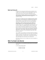
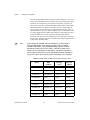
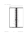
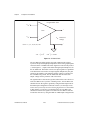
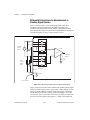
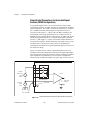
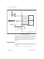
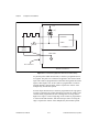
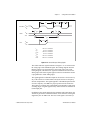
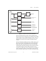
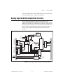
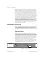
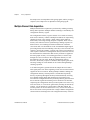
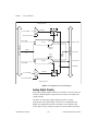
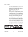
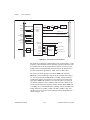
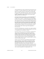
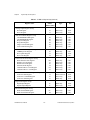
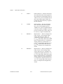
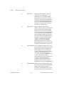
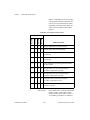
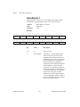
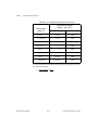
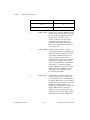
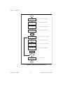
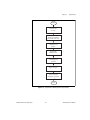
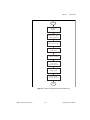
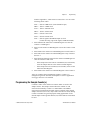
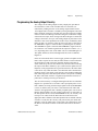
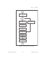
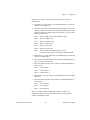
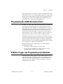
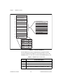
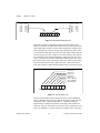
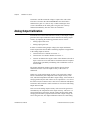
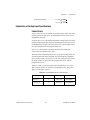
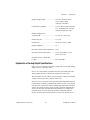
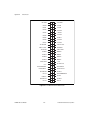
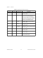
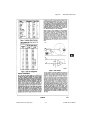
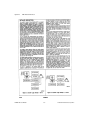
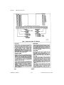
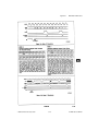
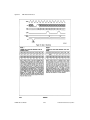
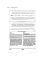
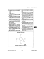
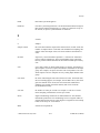
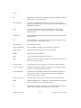
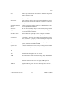
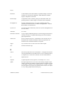
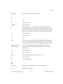
Figure 3-10. Analog Output Waveform Circuitry
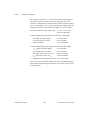
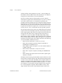
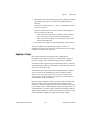
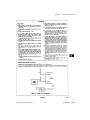
The local latch is used for immediate updating of the DACs. When data
is written to the DACs in immediate updating mode, the data is directly
routed to the DACs to be converted to a voltage at the output. In this
mode, the Update* signal is held low, or true. The only path available
for data transfer to the DACs in the immediate update mode is the local
latch. The path that the data takes to the DACs is determined by the
DAC mode enabled through a register in the AT-MIO-16X register set.
The DAC FIFO and RTSI latch are used for posted updating of the
DACs. Data written to the DACs is buffered by the DAC FIFO to be
updated at a later time. The DAC FIFO can buffer up to 2,048 values
before updating the DAC. The RTSI latch is a special case of the posted
update mode because data is not directly written to the AT-MIO-16X
board from the PC, but it is received serially from the AT-DSP2200. In
this case, only one value can be buffered before updating the DAC.
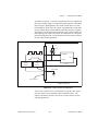
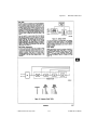
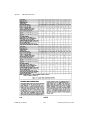
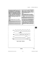
In the posted update mode, you can use any one of the three paths to
transfer data to the DACs. Data can be sent through the FIFO and local
© National Instruments Corporation
3-19
AT-MIO-16X User Manual