1
Chapter 5
Programming
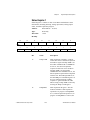
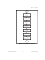
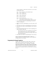
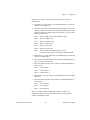
Programming the Waveform Cycle Counter
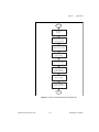
Select the appropriate counter (1, 2, or 5) from the Am9513A
Counter/Timer to be used for counting DAC buffer cycles. To program
the cycle counter, complete the following programming sequence. All
writes are 16-bit operations. All values given are hexadecimal.
1.
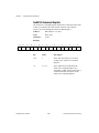
Write FF00 + n to the Am9513A Command Register to select the
Counter n Mode Register.
2.
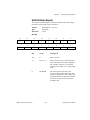
Write 0325 to the Am9513A Data Register to store the Counter n
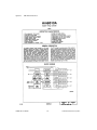
mode value. Am9513A counter mode information can be found in
Appendix C, AMD Am9513A Data Sheet.
3.
Write (FF08 + n) to the Am9513A Command Register to select the
Counter n Load Register.
4.
Write the desired cycle count to the Am9513A Data Register to
store the Counter n load value.
5.
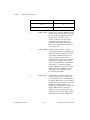
Write the following value to the Am9513A Command Register to
load Counter n.
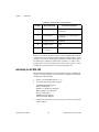
FF41 — Load Counter 1
FF42 — Load Counter 2
FF50 — Load Counter 5
6.
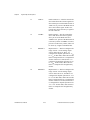
Write (FFF0 + n) to the Am9513A Command Register to decrement
Counter n.
7.
Write the following value to the Am9513A Command Register to
arm Counter n.
FF21 — Arm Counter 1
FF22 — Arm Counter 2
FF30 — Arm Counter 5
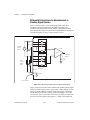
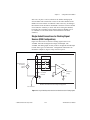
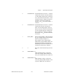
After you complete this programming sequence, Counter n is
configured to count the DAC buffer retransmit signal from SOURCE3
as soon as the load/arm counter command is written.
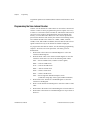
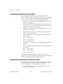
Programming the Waveform Cycle Interval Counter
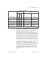
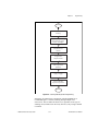
To program the cycle-interval Counter for a pulsed cyclic waveform
generation mode, use the following programming sequence. All writes
are 16-bit operations. All values given are hexadecimal.
1.
AT-MIO-16X User Manual
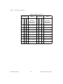
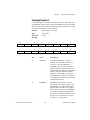
Write FF02 to the Am9513A Command Register to select the
Counter 2 Mode Register.
5-34
© National Instruments Corporation