1
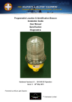
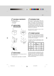
Programable Location & Identification Beacon Instalation Guide User Manual Specification Diagnostics Hardware Versions 4.2 and 4.3 Issue: 1 12th July 2013 Powered by eAGLe Light Engines ™ Interleader Limited Document Revision Sheet Issue Date Changes 1 12th July 2013 New Document for V4.2 and V4.3 Hardware. Version 4.2/4.3 hardware has: 1) Revised switch arrangements for intensity, programme and quadrant control. 2) Quadrant control switches have been relocated to the underside of the PCB to avoid accidental activation. 3) Alarm Relay output FEC eAGLe Beacon HP0680-1-3 Manual V4.2 Issue 1 120713 2 of 30 12/07/2013 Document Index Contents 1. Physical Installation ............................................................................................................. 5 2. Programme and Maximum Light Level Setting .................................................................... 6 3. Level Setting Switches ........................................................................................................ 7 4. Operational Modes – Single Colour Beacons ...................................................................... 8 5. Programme Setting Switches – Single Colour Beacons ...................................................... 9 6. Reserved Programme Switch Settings – Single Colour Beacon........................................ 10 7. Operational Modes – Multi-Colour Beacons ...................................................................... 11 8. Programme Setting Switches – Multi-Colour Beacons ...................................................... 12 9. Reserved Programme Switch Settings – Multi-Colour Beacons ........................................ 13 10. Quadrant Control Switches ............................................................................................ 14 11. Alarm Output .................................................................................................................. 16 12. Specification ................................................................................................................... 17 13. Optional Extras............................................................................................................... 18 14. Special Orders ............................................................................................................... 19 15. Spare Parts .................................................................................................................... 20 16. Appendix 1 – Timings of Location Beacon Modes ......................................................... 21 17. Appendix 2 – Identification Beacon Modes .................................................................... 22 18. Appendix 3 – FAA Helipad Beacon Modes .................................................................... 23 19. Appendix 4 – Morse Code Timing .................................................................................. 24 20. Appendix 5 – Diagnostics and Fault Finding .................................................................. 25 21. Appendix 6 - System Diagnostics................................................................................... 29 FEC eAGLe Beacon HP0680-1-3 Manual V4.2 Issue 1 120713 3 of 30 12/07/2013 Programmable Location & Identification Beacon User and Programming Guide The FEC Location and Identification Beacon can be programmed without any special knowledge, skills or tools before or after installation by means of on-board switches. In addition, on-board switches enable different maximum light output levels to be set and control which quadrants are active. Users wishing to access key system and operational data as well as programme their own PIN access control codes and the Morse Code identification strings of the unit may do so with an optional interface system that works with a Windows PC. Part Number HP0680P (White) HP0681P (Red) HP0683P (White, Green and Yellow) Model Characteristics The basic models are either single colour beacons (HP0680P, HP0681P) or multi-coloured beacons (HP0683P). The core beacon controller is the same for both but the LED arrays are different. To simplify setup, operation and on-going support the software is pre-programmed with which sort of arrays it is fitted with (single or multi-colour) and executes a suite of programmes consistent with them. The suite of programmes available is listed in later sections and includes a range of FAA, ICAO, CAA and Transport Canada consistent patterns for civil and military heliports and airfields. FEC eAGLe Beacon HP0680-1-3 Manual V4.2 Issue 1 120713 4 of 30 12/07/2013 1. Physical Installation To avoid ingress of moisture, mounting and any subsequent maintenance must only be undertaken when there is no precipitation. To begin installation, the lens clamp, glass lens and LED beacon core of the unit must be removed from the aluminium beacon base before the pole-mounted or flange-mounted base is secured to the pole or structure. The LED beacon core is a sophisticated and delicate unit and during the fitting process must be kept dry and stored in an appropriate manner to avoid damage. The power cable should be carefully threaded through the cable entry arrangement ensuring that the cable does not foul the internal fan or other parts of the unit. Alignment To ensure that the light pattern from the beacon is at the correct angle, a spirit level or similar must be used to ensure that the base is perfectly level. Particlaur care must be taken with the alignment of flange mounted bases to ensure that the LED arrays, once aligned via the spring pin (below) enables the arrays to be aligned as desired. Small angular adjustments of pole-mounted bases can be performed by slackening the Alan screw and lock nut and rotating the base. To enable correct alignment of the arrays, particularly if the Array Disable function is to be used, the pole-mounted or flange-mounted base must be oriented so that the spring pin in the recess which aligns with a locating notch in the beacon core base plate is placed in the desired direction. Unit Base Plate alignment slot correctly positioned over the Spring Pin FEC eAGLe Beacon HP0680-1-3 Manual V4.2 Issue 1 120713 5 of 30 12/07/2013 2. Programme and Maximum Light Level Setting Switch locations 4 Amp Fuse The Programme and Maximum Light Level control switches are located on the edge of the main circuit board of the beacon as indicated on the diagram to the right. Details of their setting are described below and in the next sections. All switches can be set using the tip of a ball point pen or similar tool. Depending on the model, the switches will be set to appropriate default values detailed below and in later sections. The main fuse is also shown. Level Setting Switches Programme Switches and Level Programme Setting Switches Setting Level Switches o 2 way switch identified as SW2 with ‘Level’ printed by it. Photo shows Level set to 3 Programme Switches o 3 way switch identified as SW1 with ’Prog’ printed beside it. Photo shows Programme 0 selected FEC eAGLe Beacon HP0680-1-3 Manual V4.2 Issue 1 120713 6 of 30 12/07/2013 3. Level Setting Switches The Level Setting switches enable the maximum flash brightness to be set to 4 levels. All changes to the level switches must be made with the unit powered off. The switches are best moved with the tip of a stylus, jeweller’s screwdriver or similar tool. Note that the switches may be covered with a protective adhesive tape. To allow changes to be made this can be removed and discarded. Note that in this and later tables the switch actuators are shown in red for clarity. The levels are as follows: Switch Setting Value Level 0 10% of Maximum Level 1 30% of Maximum Level 2 60% of Maximum Level 3 100% of Maximum Level (Default - as set in photo on previous page) Note that the unit monitors the temperature of the LED arrays and if it exceeds critical thresholds will automatically reduce the LED power until the temperature recovers. This is most likely to occur at high ambient temperatures and/or dense Morse strings (see appendix for Morse timings) FEC eAGLe Beacon HP0680-1-3 Manual V4.2 Issue 1 120713 7 of 30 12/07/2013 Operational Modes – Single Colour Beacons 4. If the beacon is a single colour unit, the modes that can be selected are (see Appendix 1 and 2 for details): 2 Location beacon modes: o Modified ICAO pattern (short [2mS] and long [ 25mS] pulse) - 30 FPM o 25 FPM (Flashes Per Minute) UK CAA and Transport Canada timing compliant 2 Morse beacon modes: 4 - 6 WPM (Words Per Minute): o 1, 2 and 3 character code options (defined at time of ordering) o User programmable (with optional extra programming kit) Rotating (simulated) beacon mode ‘Jump’ Flash mode – Highly visible flashing mode Test and Setup Mode – Allows users to monitor all of the units parameters and set security PIN codes and Morse codes (with optional extra interface system) There are 8 reserved programmes for future development FEC eAGLe Beacon HP0680-1-3 Manual V4.2 Issue 1 120713 8 of 30 12/07/2013 5. Programme Setting Switches – Single Colour Beacons The Programme Setting switches enable the different operating modes of the unit to be set. All changes to the Programme switches must be made with the unit powered off for them to take effect. The switches are best moved with the tip of a stylus, jeweller’s screwdriver or similar tool. Note that the switches may be covered with a protective adhesive tape. To allow changes to be made this can be removed and discarded. The Programmes are as follows (see Appendix 1 & 2 for detailed timing): Switch Setting Value Programme 0 ICAO Helipad Beacon ICAO compliant timing 1 Modified ICAO Helipad Beacon (Default Setting) Modified ICAO compliant timing giving longer flashes within the same period 2 Morse Identification Beacon #1 (1, 2 or 3 Characters) Factory set default is ‘H’ (Transport Canada compliant) Can be user programmed with optional kit 3 Morse Identification Beacon #2 (1, 2 or 3 Character) Factory set default is ‘TST’ for Test. Can be user programmed with optional kit 4 Location Beacon In this mode the unit flashes at 25 Flashes/Minute consistent with UK CAA CAP168 timing requirements 5 ‘Rotating’ Beacon In this mode the LED arrays are fired in sequence to create the effect of a rotating beacon (~ 70 RPM) 6 ‘Jump’ Flash In this mode alternate pairs of LED arrays are fired to create a very visible warning pattern 7 Test, Setup and Demonstration Testing, diagnostics and demonstration and for user programming with optional kit Note that to use Programme 7, (Test, Setup and Demonstration), requires a PC and the optional Terminal Programming Kit. FEC eAGLe Beacon HP0680-1-3 Manual V4.2 Issue 1 120713 9 of 30 12/07/2013 6. Reserved Programme Switch Settings – Single Colour Beacon The following programmes are reserved for future development. Switch Setting Value Programme 8 Reserved Programme # 1 9 Reserved Programme # 2 10 Reserved Programme # 3 11 Reserved Programme # 4 12 Reserved Programme # 5 13 Reserved Programme # 6 14 Reserved Programme # 7 15 Reserved Programme # 8 Selecting any of the above, if not specially programmed, will stop the beacon from working. FEC eAGLe Beacon HP0680-1-3 Manual V4.2 Issue 1 120713 10 of 30 12/07/2013 Operational Modes – Multi-Colour Beacons 7. If the beacon is a multi-colour unit, the modes that can be selected are (see Appendix 1, 2 and 3 for details): FAA L-802H Civil Helipad Beacon o 36 Flashes per Minute, 75ms pulses FAA L-802M Military Helipad Beacon o 17.3 Flashes per Minute, 100ms pulses US Army Helipad Beacon o 36 Flashes per Minute, 50ms pulses Location beacon mode: o Modified ICAO pattern (25mS pulse) - 30 FPM o 25 FPM (Flashes Per Minute) UK CAA and Transport Canada timing compliant 2 Morse beacon modes: 4 - 6 WPM (Words Per Minute): o 1, 2 and 3 character code options (defined at time of ordering) o User programmable (with optional extra programming kit) Test and Setup Mode – Allows users to monitor all of the units parameters and set security PIN codes and Morse codes (with optional extra interface system) There are 8 reserved programmes for future development FEC eAGLe Beacon HP0680-1-3 Manual V4.2 Issue 1 120713 11 of 30 12/07/2013 8. Programme Setting Switches – Multi-Colour Beacons The Programme Setting switches enable the different operating modes of the unit to be set. All changes to the Programme switches must be made with the unit powered off for them to take effect. The switches are best moved with the tip of a stylus, jeweller’s screwdriver or similar tool. Note that the switches may be covered with a protective adhesive tape. To allow changes to be made this can be removed and discarded. The Programmes are as follows (see Appendix 1, 2 & 3 for detailed timing): Switch Setting Value Programme 0 FAA L-802H Civil Helipad Beacon (Default Setting) 36 Flashes per Minute, 75ms pulses White – Green - Yellow 1 Modified ICAO Helipad Beacon Modified ICAO compliant timing 25ms flashes within the defined cycle period 2 Morse Identification Beacon #1 (1, 2 or 3 Characters) Factory set default is ‘H’ (Transport Canada compliant) Can be user programmed with optional kit 3 Morse Identification Beacon #2 (1, 2 or 3 Character) Factory set default is ‘TST’ for Test. Can be user programmed with optional kit 4 Location Beacon In this mode the unit flashes at 25 Flashes/Minute consistent with UK CAA CAP168 timing requirements 5 US Army Helipad Pattern (as per TM 5-811-5) 36 Flashes per Minute, 50ms pulses White (double Peak) – Green - Yellow 6 FAA L-802M Military Helipad Beacon 17.3 Flashes per Minute, 100ms pulses Green – White-White 7 Test, Setup and Demonstration Testing, diagnostics and demonstration and for user programming with optional kit Note that to use Programme 7, (Test, Setup and Demonstration), requires a PC and the optional Terminal Programming Kit. FEC eAGLe Beacon HP0680-1-3 Manual V4.2 Issue 1 120713 12 of 30 12/07/2013 9. Reserved Programme Switch Settings – Multi-Colour Beacons The following programmes are reserved for future development. Switch Setting Value Programme 8 Reserved Programme # 1 9 Reserved Programme # 2 10 Reserved Programme # 3 11 Reserved Programme # 4 12 Reserved Programme # 5 13 Reserved Programme # 6 14 Reserved Programme # 7 15 Reserved Programme # 8 Selecting any of the above, if not specially programmed, will stop the beacon from working. FEC eAGLe Beacon HP0680-1-3 Manual V4.2 Issue 1 120713 13 of 30 12/07/2013 10. Quadrant Control Switches There may be situations where an operator requires that the beacon is only visible from certain directions (for example, to avoid dazzling pilots or causing a distraction). Usually this would require the operator to fit screening or similar but with the FEC Programmable Location & Identification Beacon this is simply achieved by disabling the relevant array(s) by means of switches on the main circuit board. To avoid accidental activation, the Array Enable switches are located on the underside of the main circuit board and accessed through an aperture in the mounting plate (picture below left). Each array has an ‘Array Enable’ switch associated with it. To disable a particular array simply slide the switch to OFF (Disable). The switches are best moved with the tip of a stylus, jeweller’s screwdriver or similar tool. Note that the switches may be covered with a protective adhesive tape. To allow changes to be made this can be removed and discarded. The relevant array(s) will remain permanently disabled in all programming modes until the switch(es) are turned on again. As shipped, all of the arrays are enabled (all Array Enable switches – On) giving the full 360 o pattern as shown below. Examples of array control are shown over. Array Enable Switches FEC eAGLe Beacon HP0680-1-3 Manual V4.2 Issue 1 120713 14 of 30 12/07/2013 Example Array Enable Switch Settings Array Enable Switch Setting Array Condition Light Pattern All Arrays Enabled (On) Array #1 Disabled (Off) Array #2 Disabled (Off) Array #3 Disabled (Off) Array #4 Disabled (Off) Arrays #1 & 2 Disabled (Off) Arrays #1 & 3 Disabled (Off) Arrays #1, 2 & 3 Disabled (Off) NB: Ensure that after installation Array Enable Switches are correctly set. Failure to do so will give appearance of LED Failure FEC eAGLe Beacon HP0680-1-3 Manual V4.2 Issue 1 120713 15 of 30 12/07/2013 11. Alarm Output The beacon is fitted with an alarm relay output for remote monitoring. The alarm condition is flagged if: 1) The supply voltage falls below 40V 2) The array temperature gets too high 3) An array (or single colour element) of an array fails – Checked on start-up The alarm relay output is via a terminal connector located on the underside of the main circuit board and accessed via a slot in the base plate as shown opposite: Alarm Relay Output The relay output is electrically isolated from the supply feed and ground and can be connected to an alarm monitoring device. The maximum voltage, current and power are shown in the table below. The non-alarm condition for the relay is ‘Contact Open’. The alarm condition for the relay is ‘Contact Closed’ Note – For safety reasons, the beacon will attempt to operate even though it is in an alarm condition. For example if the array temperature is too high, the alarm will be set but the beacon will continue to operate at reduced power output. Contact Data Condition Max. Units Contact Rating Any combination of the switching voltage and current must not exceed the given rated power 10 W Switching Voltage DC or Peak AC 170 V Switching Current DC or Peak AC 0.5 A Carry Current DC or Peak AC 0.5 A 250 mΩ Static Contact Measured with Nominal Voltage Resistance (initial) FEC eAGLe Beacon HP0680-1-3 Manual V4.2 Issue 1 120713 16 of 30 12/07/2013 12. Specification Physical Characteristics 7 1/16 inches tall (177.8mm) 1” NPT hub for pole mounting (also available with three point flat flange mount) Locating pin in base to enable precise orientation for quadrant management Degree of protection IP66 Operating temperature: -25oC to +50oC Storage temperature: -25oC to +80oC Long-life, quiet and low-power Internal cooling fan Electrical Characteristics Operating voltage: Absolute voltage range Average power consumption: Instantaneous power consumption: Electrical protection o On-board fuse: o Transient Voltage Suppression: o Reverse voltage protection: o LED controllers (4 off): LED Lifetime (projected): 48V (can operate from batteries) 40V – 55V DC Less than 20 watts 150 watts 4 Amp (spare fuse on board) Clipped at 55V, 600 watt peak Full – unit is polarity agnostic Short circuit and overvoltage protected >50,00 hours LED Colour Characteristics White: Red: Green: Yellow: 6000oK/6500oK ‘Cool White’ 625nm 528nm 590nm Options Red-Orange Hyper Red Deep Blue 617nm 656nm 455nm Power Supply 100-230V 50/60Hz 240W solid state power supply 48V 5A DC output Full over-voltage protected Short circuit and over current protected Free air cooling (no fan) IP65 rated 9 ¾” long, 2 ¾” Wide, 1 ½” High (246mm Long, 70mm Wide, 38mm High) 1’ (300mm) AC and DC connection leads FEC eAGLe Beacon HP0680-1-3 Manual V4.2 Issue 1 120713 17 of 30 12/07/2013 13. Optional Extras Programming Kit (for use with User supplied PC) USB interface and power cable CD contains: o Drivers – automatic installation for Windows XP through Windows 7 o Terminal Software – Provides a screen/keyboard interface to unit o Instructions – How to install and run the software and make user changes to PIN codes and Morse Codes Wireless Interface Kit (requires the above) Wireless interface between a beacon (or beacons) and a PC Fits securely inside beacon Powered from beacon No wiring involved Wireless interface may be specified at time of order or is available as a simple user upgrade kit (contains all that is required to upgrade existing units) Simple in-situ upgrade Depending on terrain and local topology has a range of 1km to allow remote monitoring of beacons Image (top) – Screen output Image (middle) - Kit comprising USB Wireless interface and Beacon Adapter Image (bottom) - Beacon Adaptor mounted in unit (Version 4.1 hardware) FEC eAGLe Beacon HP0680-1-3 Manual V4.2 Issue 1 120713 18 of 30 12/07/2013 14. Special Orders Colours At additional cost, units can be supplied with a range of colour LEDs including: Red-Orange Hyper Red Deep Blue 617nm 656nm 455nm Software Features At additional cost, units can be programmed to perform non-standard patterns including: Different string lengths of Morse Code Non-standard timing flash patterns Co-ordinated beacon operation (requires wireless interface for all beacons involved) FEC eAGLe Beacon HP0680-1-3 Manual V4.2 Issue 1 120713 19 of 30 12/07/2013 15. Spare Parts The following spare parts, with all tools and consumables where required, are available and can be fitted by users: LED Arrays LED Array replacement kits are available for all multicolour (left image) and single (right image) arrays. The kits comprise: LED array Allen key Stainless steel screws (4 off) Full instructions Cooling Fan A cooling fan replacement kit is available comprising: Fan with flying lead and connector Allan key Stainless steel screws (3 off) Full instructions Fuses A spare fuse is provided with every unit, attached to the underside of the circuit board. Spare fuses are available but repeated blowing of the fuse would indicate a major fault and necessitate the return of the unit for repair. Note For LED and Fan fitting, user must supply thread locking compound (Loctite medium 248 or similar) Enclosure The following mechanical parts are available (no tools required): Glass lens Rubber gasket Securing strap Other Apart from the items listed above, there are no other user-serviceable parts. Any repair would require the unit to be returned for repair or replacement. FEC eAGLe Beacon HP0680-1-3 Manual V4.2 Issue 1 120713 20 of 30 12/07/2013 16. Appendix 1 – Timings of Location Beacon Modes FEC eAGLe Beacon HP0680-1-3 Manual V4.2 Issue 1 120713 21 of 30 12/07/2013 17. Appendix 2 – Identification Beacon Modes FEC eAGLe Beacon HP0680-1-3 Manual V4.2 Issue 1 120713 22 of 30 12/07/2013 18. Appendix 3 – FAA Helipad Beacon Modes Mode 0: FAA L-802H Civil Helipad Beacon Mode 5: US Army Helipad Pattern (as per TM 5-811-5) Mode 6: FAA L-802M Military Helipad Beacon FEC eAGLe Beacon HP0680-1-3 Manual V4.2 Issue 1 120713 23 of 30 12/07/2013 19. Appendix 4 – Morse Code Timing FEC eAGLe Beacon HP0680-1-3 Manual V4.2 Issue 1 120713 24 of 30 12/07/2013 20. Appendix 5 – Diagnostics and Fault Finding The following are the range of simple tests that an end-user of the beacon can perform – to be carried out in the order given. Warnings Only fully qualified electricians/technicians should perform electrical testing of the unit, particularly the 110V-240V mains feed and Power Supply Unit. The beacon emits very high brightness light pulses. Do not look directly at the LED arrays or near reflections of the light. During normal operation the LED array can reach elevated temperatures that may cause burning. Do not touch the LED array until fully cooled Basic Configuration and Connection Checks – Ensure that: 1. The beacon is properly mounted, secure and appears physically undamaged 2. If there are any signs of damage to any part of the beacon, power supply or wiring do not go any further but refer the unit to FEC for repair 3. The Power Supply Unit is properly connected to a live mains supply 4. The 48V DC feed wiring to the beacon is continuous and that all connections appear sound Beacon configuration Setting Switches – Ensure that: 1. The Level Setting Switches are set to the required intensity a. See section 3 2. The Programme Switches are set to the required flash programme a. See section 5 & 6 – Single Colour Beacon b. See section 8 & 9 – Multi Colour Beacon 3. All of the Quadrant Enable Switches are set to ON a. See section 10 Observational Testing Once all of the above have been checked, power the unit on. Under normal circumstances there will be a few seconds delay, all of the arrays will flash very quickly in turn and colour (the system is checking all of the arrays and colours) then the beacon will perform the selected programme. Note that the control system of the LED monitors a number of parameters to ensure that the beacon flashes consistently at the desired brightness. If it detects that this is not possible, it will not flash at all. If it does not operate normally, check the status LEDs on the main circuit board (diagram on next page). FEC eAGLe Beacon HP0680-1-3 Manual V4.2 Issue 1 120713 25 of 30 12/07/2013 Check status of the red ‘Feed’ LED 1. Feed LED is illuminated – Power is being fed to the beacon and fuse is OK 2. Feed LED is not illuminated – Power is not being fed to the beacon OR the 4 Amp fuse is blown Image of status LEDs, Fuse and Array 1 Disable Switch – V4.2 Hardware ‘CPU’ LED ‘Feed’ LED 4 Amp Fuse If a blown fuse is suspected then: 1. 2. 3. 4. Disconect all power from the Power Supply Unit. Remove the 4 Amp fuse and test with a fuse tester or Ohm meter. If the fuse is sound, replace it and re-try the tests. If the fuse is blown, replace with spare fuse carried on the underside of the circuit board (see section 15 – Spare fuse). NB – repeated fuse blowing indicates a serious fault which must be reported to FEC. If after above checks have been made and the Feed LED remains un-lit, either continue with the ‘Electrical Tests’ below or return beacon to FEC for checking. If the red Feed LED is lit then proceed to check status of the green ‘CPU’ LED. FEC eAGLe Beacon HP0680-1-3 Manual V4.2 Issue 1 120713 26 of 30 12/07/2013 Check status of the green ‘CPU’ LED 1. CPU LED is illuminated – The 5V voltage regulator for the on-board processor is working 2. CPU LED is not illuminated – The 5V voltage regulator for the on-board processor is NOT working If both LEDs are lit then power is being provided to the beacon and its processor. If all of the switches have been correctly set and the beacon is still not working it indicates a fault that must be referred to FEC for rectification. Electrical Tests Warning Only fully qualified electricians/technicians should perform electrical testing of the unit, particularly the 110V-240V mains feed and Power Supply Unit. Feed Voltage The beacon has a nominal feed voltage of 48V DC with an absolute range of 40V to 55V. The +ve supply is normally connected to J1/1 (Brown cable) but polarity is not critical. The beacon is fitted with a Transient Voltage Suppressor to protect against voltage spikes, typically caused by near but not direct lightning strikes. If a voltage above 55V is applied to the beacon the TVS will clamp the input and blow the fuse to protect the unit. The beacon monitors its feed voltage and, if it is below 40V on start-up, will disable the LEDs and enter the Test and Diagnostic routine (as though program 7 had been selected). This is to ensure that both excessive current is not drawn from the supply and to ensure that the beacon only operates at the intended level of brightness. One consequence of this is that if a supply with a slow ‘rise time’ (i.e. the time it takes to achieve its set voltage) is too slow the beacon may detect this as a low feed voltage and enter the Test and Diagnostics routine. If a bench power supply is to be used for testing it must be set to 48V for testing and the current limit set to a minimum of 4 amps once initial tests have been performed. If a bench power supply is used for the LED status checks above, it may be set to a low voltage and current limits (e.g. 12V and 200mA) but once this is completed, reset to the normal limits (48V/4A) and re-started for the full LED tests. Feed Current At the rated feed voltage of 48V the beacon’s quiescent current is of the order of 100mA. The beacon’s peak current demand is >3 amps for the duration of the LEDs flash. If the power supply used is not able to meet this peak demand, with no appreciable drop in voltage, the beacon may enter the Test and Diagnostic routine and the LEDs will not flash. FEC eAGLe Beacon HP0680-1-3 Manual V4.2 Issue 1 120713 27 of 30 12/07/2013 Voltage Test Points The following tests may be made in addition to those outlined above and require the use of a DC voltmeter applied to the probe points below. Notes: 1. The circuit board has been coated in a water-proof clear acrylic coating. To make connections will require the careful use of pointed probes to contact the lands. 2. The circuit employs a ‘floating earth’. The fixing screws/metalwork are not connected to the beacon’s 0V line. 6 4 5 3 0 0 2 1 Image of Voltage Test Points (above) and schematic (below) 3 4 5 6 3 1 2 0 0 The voltage tests should be carried out in the following order (with a 48V supply): Test Points Reading Comment 1-2 48V Input feed voltage. If not 48V, check supply 2-3 48V Input feed to fuse. If not 48V, check fuse seating 2-4 48V Output from fuse. If not 48V, check fuse/fuse seating 0-6 ~46V Output from Bridge. If not 46V, bridge faulty – return to FEC 0-5 5V Output from regulator. If not 5V, regulator faulty – return to FEC FEC eAGLe Beacon HP0680-1-3 Manual V4.2 Issue 1 120713 28 of 30 12/07/2013 21. Appendix 6 - System Diagnostics If the Programming Kit (with or without the wireless option) is available, the following parameters may be checked: The best way to power a beacon not fitted with a wireless interface is to remove all power feeds to it and power via the USB lead of the programming kit. For beacons fitted with a wireless interface, power the beacon from a suitable power source – a laboratory power supply set at a low voltage is ideal. In the above screen shot the following Unit History parameters should be checked: System Ensure that the Model, Hardware and Software are expected and match the labels on the LED and the base plate. Status Check that the Input Voltage matches the supply voltage (in this example 5V from the USB) and that the LED Array Temperature is showing the current temperature. If the Array Temperature is not showing correctly (usually within a few degrees of room temperature) this may indicate a faulty temperature probe. In this example, 24 degrees Celsius is consistent with the room temperature at the time of the reading. If the figure is extremely high (>100 degrees when the LEDs are not running) this clearly indicates a fault with the temperature probe which will lead to the unit running permanently at much reduced power and light output. FEC eAGLe Beacon HP0680-1-3 Manual V4.2 Issue 1 120713 29 of 30 12/07/2013 Unit History Historical parameters are written at start-up and then every minute while the unit is running. When reviewing the data it is important that very short transients (e.g. a very high but short duration voltage spike) will not necessarily be captured and recorded. Never-the-less the data gives insights into the past operation of the unit. Maximum Input Voltage - In this case it is 50V and therefore within limits. A figure over 55V indicates that the unit has been over stressed. Maximum Array Temperature – In this case 37 degrees Celsius is indicated and is low because the unit has only recently been reset. A figure above 70 degrees would normally be expected. A figure up to 85degrees C is within limits but above that could indicate a fault or prolonged running at high ambient temperatures. Unit and Fan Run Times - If the Fan Run Time is nearly equivalent to the Unit Run Time it indicates prolonged running at high ambient temperatures. FEC eAGLe Beacon HP0680-1-3 Manual V4.2 Issue 1 120713 30 of 30 12/07/2013