1
line of Allen-Bradley PLCs program so similarly to the MicroLogix line.
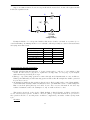
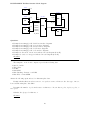
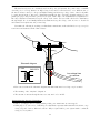
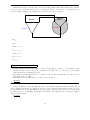
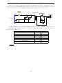
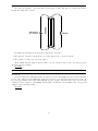
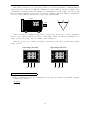
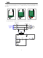
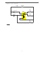
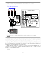
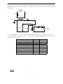
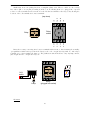
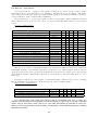
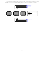
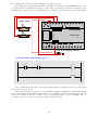
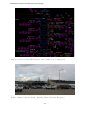
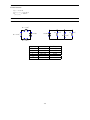
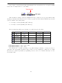
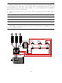
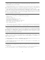
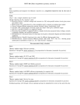
This example shows an Allen-Bradley MicroLogix 1000 series PLC (model 1761-L10BWA) wired to two
toggle switches and one LED indicator lamp, complete with a demonstration program. Note that line power
(120 VAC) wire connections to power the PLC have been omitted, so the focus is solely on the I/O wiring:
Toggle switch
24V
DC
COM
I/0
I/1
I/2
I/3
DC
COM
I/4
I/5
DC OUT
Allen-Bradley
Power
Run
MicroLogix
Fault
1000
Force
85-264 VAC
L1
VAC
VDC
L2/N
O/0
VAC
VDC
O/1
VAC
VDC
O/2
VAC
VDC
O/3
LED (with dropping resistor)
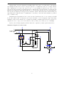
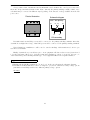
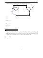
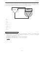
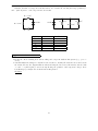
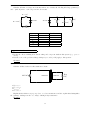
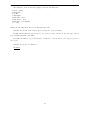
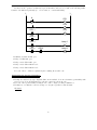
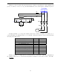
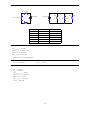
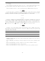
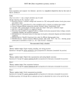
Ladder-Diagram program written to PLC:
I:0
I:0
O:0
0
1
0
END
Note how Allen-Bradley I/O is labeled in the program: input bits designated by the letter I and output
bits designated by the letter O.
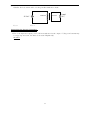
Based on the wiring and program you see for this PLC, identify the switch state combinations resulting
in an energized lamp. Try duplicating this program in your own PLC (even if it is a different brand or model)
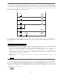
and see how it functions. Be sure to activate the color highlighting feature of your programming editor so
you may see the “live” status of the program’s virtual contacts and coil!
118