1
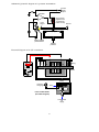
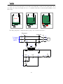
Answer 71
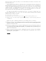
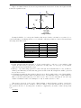
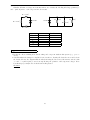
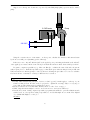
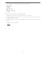
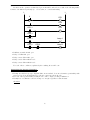
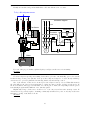
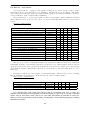
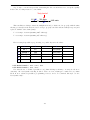
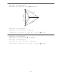
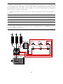
Step 1 should ensure zero energy at the motor. Step 2 alerts others not to re-energize the motor. Step 3
is a check to see that the correct motor has been locked out. Step 4 checks for voltage at all possible 2-point
combinations on the power conductors. Step 5 verifies that the voltmeter is properly functioning.
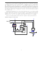
Pulling a fuse on a control circuit forces the motor contactor to be a safety device, which it was never
intended to be. Furthermore, it makes re-energizing the motor as simple as replacing a low-voltage fuse,
which is far too easy (and therefore likely) for someone to do.
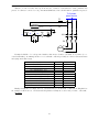
Answer 72
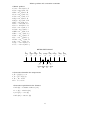
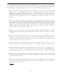
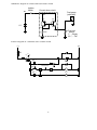
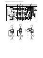
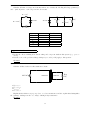
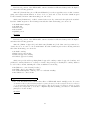
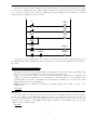
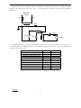
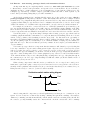
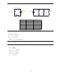
Fault
Fuse F1 blown
Fuse F2 blown
Start switch failed open
Stop switch failed open
M1 coil failed open
M1 auxiliary contact failed open
M1 power contact(s) failed open
OL contact failed open
Start switch failed shorted
Stop switch failed shorted
Transformer secondary failed shorted
Possible
√
√
Impossible
√
√
√
√
√
√
√
√
√
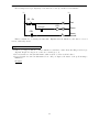
Answer 73
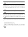
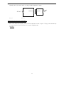
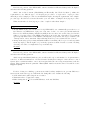
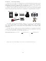
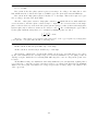
Truth table (good circuit)
A
0
0
1
1
Truth table (with fault)
B Output
0
0
1
0
0
1
1
0
A
0
0
1
1
B Output
0
0
1
0
0
1
1
1
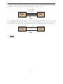
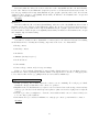
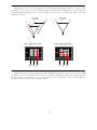
If you thought that the “faulted” truth table would be all 0’s, you probably thought I said relay contact
CR2 failed open. The fault I proposed was relay CR2 coil failed open.
Answer 74
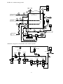
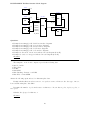
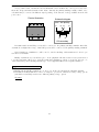
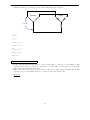
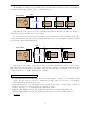
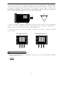
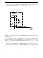
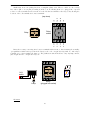
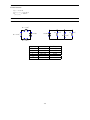
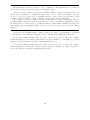
Never, ever connect load devices in series in a control circuit such as this!
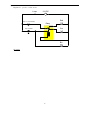
Answer 75
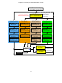
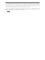
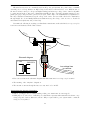
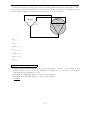
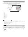
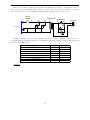
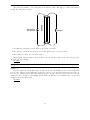
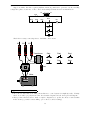
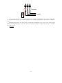
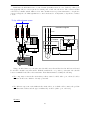
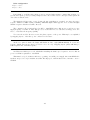
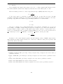
The blue lamp will be energized whenever the pressure switch senses a pressure that is less than 45 PSI.
The red and green lamps will both be de-energized whenever the level senses a level less than 1 foot
3 inches. If that switch senses a level greater than 1 foot 3 inches, either the red lamp or the green lamp
will energize (not both simultaneously!) based on the pressure switch’s state: a pressure less than 45 PSI
energizes the relay coil and energizes the green lamp, while a pressure greater than 45 PSI de-energizes the
relay coil and energizes the red lamp.
163