1
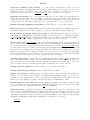
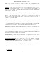
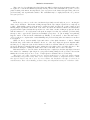
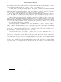
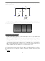
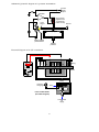
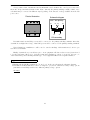
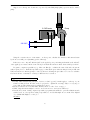
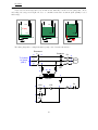
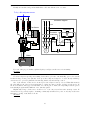
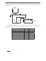
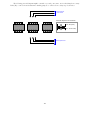
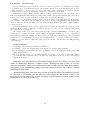
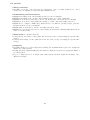
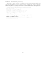
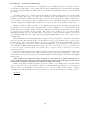
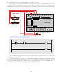
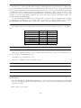
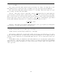
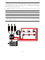
An electrician needs to perform some routine “megger” measurements on the electric pump motor.
“Megger” is the brand name of a high-voltage ohmmeter used to check the integrity of electrical insulation
in electric motors, transformers, and other devices with wire coils subject to faults due to corrosion, vibration,
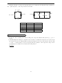
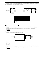
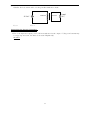
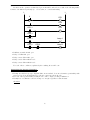
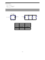
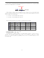
or overheating. Here, the electrician will check resistance between each of the motor’s terminals (T1, T2, T3)
and the metal frame of the motor, ensuring there are many millions of ohms (open) as the wire insulation
should provide.
Like all ohmmeter tests, a “megger” check must be performed on a device that is unpowered. For this
reason, and also for personal safety, the electrician must ensure no power will get to the motor during his
test.
Before commencing the test, the electrician follows this procedure to ensure the motor is in a zero energy
state:
(1)
(2)
(3)
(4)
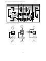
Turn off the disconnect switch
Place a padlock and a danger tag on the switch’s handle to ensure it cannot turn on
Push the “Start” pushbutton switch to check that the pump does not start up
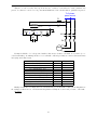
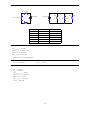
Use an AC voltmeter to verify 0 volts between the following test points:
(a) Voltage between terminals K and L
(b) Voltage between terminals K and M
(c) Voltage between terminals L and M
(d) Voltage between terminals K and earth ground
(e) Voltage between terminals L and earth ground
(f ) Voltage between terminals M and earth ground
(5) Use the same AC voltmeter to verify 480 volts between any two of the L1, L2, and L3 test points
Explain the rationale behind each step in this sequence. Although this many steps may appear to be a
bit paranoid, there is actually logical justification for each one.
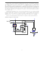
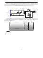
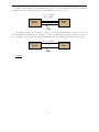
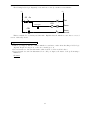
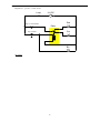
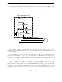
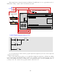
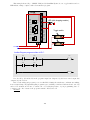
Suppose another electrician looked at this diagram and declared, “We don’t actually have to turn the
disconnect switch off – we can prevent power from getting to the motor’s terminals just by just pulling any
one of the fuses in this circuit! If the M1 coil can’t energize with 120 volts, then the M1 contactor relay
cannot close, which effectively locks out 480 volt power from getting to the motor.”
What would be your response to this electrician’s suggestion, and why?
Suggestions for Socratic discussion
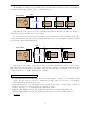
• A good logical technique for justifying each step in the lock-out/tag-out sequence is to think of a
dangerous condition (such as a test equipment fault) that would go undetected if that step were skipped.
If you can think of just one possible failure uniquely detected by a step, then that step is justified beyond
any doubt!
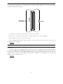
• What sort of information do you think the electrician should write on the danger tag?
• Why do you suppose it is necessary to use high voltage to test the insulation integrity of an electric
motor? Why not just use a regular ohmmeter that only uses a few volts between the test probes?
file i03403
81