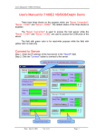
1
7188E Series
7188E Series Hardware User’s Manual
7188E Series New Features
1. Virtual COM Technology
Your Powerful Tools
2. Ethernet I/O Technology
3. Web-server Technology
Create New Ideas
4. MiniOS7 & Xserver Inside
5. I/O Expansion Bus Inside
Create New Applications
6. Time to market & Cost Effective Solution
Warranty
All products manufactured by ICP DAS are under warranty regarding
defective materials for a period of one year, starting from the date of
delivery to the original purchaser.
Warning
ICP DAS assumes no liability for damages resulting from the use of this
product. ICP DAS reserves the right to change this manual at any time
without notice. The information furnished by ICP DAS is believed to be
accurate and reliable. However, no responsibility is assumed by ICP
DAS for its use, nor for any infringements of patents or other rights of
third parties resulting from its use.
Copyright
Copyright 2002 by ICP DAS. All rights are reserved.
Trademark
The names used for identification only may be registered trademarks of
their respective companies.
7188E Series Hardware User’s Manual, 2004, v2.2, 7MH-016-22 ----- 1
Table of Contents
1.
2.
3.
4.
5.
INTRODUCTION ..............................................................................................................................................................3
1.1
PACKAGE LIST & RELEASE NOTE ................................................................................................................................3
1.2
WHY ETHERNET SOLUTIONS? ......................................................................................................................................4
1.3
WHY VXCOMM TECHNOLOGY? ...................................................................................................................................5
1.4
WHY XSERVER TECHNOLOGY?....................................................................................................................................9
1.5
WHY WEB SERVER TECHNOLOGY?............................................................................................................................11
1.6
7188EX, 7188EA & 7188EN SERIES ........................................................................................................................12
TYPICAL APPLICATIONS OF 7188E SERIES ..........................................................................................................13
2.1
RS-232/485/422 DEVICES NETWORKING ..................................................................................................................13
2.2
ETHERNET I/O APPLICATIONS ...................................................................................................................................16
2.3
LINK 7000 SERIES MODULES TO ETHERNET ..............................................................................................................18
2.4
CONTROL THOUSANDS OF I/O BY SINGLE-PC............................................................................................................21
2.5
CONNECT RS-232/422/485 DEVICES & I/O SIGNALS ................................................................................................23
2.6
CONFIGURABLE ETHERNET DATA LOGGER................................................................................................................24
DIAGNOSTICS OF THE 7188E SERIES......................................................................................................................26
3.1
APPLY POWER TO 7188E ...........................................................................................................................................26
3.2
LINKING TO PROGRAM-DEVELOPMENT PC................................................................................................................30
3.3
CONFIGURE WIZARD ..................................................................................................................................................33
I/O EXPANSION BUS FOR 7188E SERIES .................................................................................................................40
4.1
DEFINITION ................................................................................................................................................................42
4.2
PARALLEL BUS ..........................................................................................................................................................44
4.3
SERIAL BUS................................................................................................................................................................49
HARDWARE INFORMATION......................................................................................................................................54
5.1
FEATURES ..................................................................................................................................................................54
5.2
PIN ASSIGNMENT .......................................................................................................................................................55
5.3
SPECIFICATIONS .........................................................................................................................................................73
5.4
BLOCK DIAGRAM .......................................................................................................................................................78
5.5
THE WIRE CONNECTION OF 7188EN SERIES .............................................................................................................81
5.6
DIMENSION AND MOUNTING ......................................................................................................................................87
7188E Series Hardware User’s Manual, 2004, v2.2, 7MH-016-22 ----- 2
1.
Introduction
1.1 Package List & Release Note
Package List
In addition to this manual, the package includes the following items:
One 7188E hardware module
One hardware user’s manual (this manual)
One software user’s manual
One release note
One software utility disk or CD
One download cable, CA0910
Note:
If any of these items are missed or damaged, contact the local distributors for
more information. Save the shipping materials and cartons in case you want to
ship in the future.
Release Note:
It is recommended to read the release note & README.TXT first. The
release note is given in the shipping. The README.TXT is given in the
CD\README.TXT. Some important information is given in the release note &
CD\README.TXT
Order Information:
Call distributor for details.
More Quick Start:
Step 1: Refer to section 3 of this manual for general quick start
Step 2: Refer to CD\napdos\7188e\document\7188E_Quick_Start.pdf for
module specific quick start. The special modules are given as follows:
7188E1, 7188E2, 7188E3, 7188E4, 7188E5, 7188E8
7188EX, 7188EA
7188EX+X???
It is recommended to begin with quick start to get complete information.
Firmware of Default Shipping:
MiniOS7
CD\napdos\7188e\minios7\???.img
Firmware
CD\napdos\7188e\TCP\vxcomm\Server(7188e)\*.*
no.
7188E Series Hardware User’s Manual, 2004, v2.2, 7MH-016-22 ----- 3
by model
1.2 Why Ethernet Solutions?
“Embedded Internet” and “Embedded Ethernet” are hot topics today.
Nowadays Ethernet protocol has become the de-facto standard for local area
networks. Via the Internet, connectivity is occurring everywhere, from home
appliances, to vending machines, to testing equipment, to UPS...etc. Many
embedded designers now face the dilemma of adding an Ethernet interface to
their products (either for use with local networks or for connecting to the
Internet). Solutions to this problem include both hardware and software.
Connecting via Ethernet requires a communication protocol called TCP/IP. The
installed base of Ethernet networks is huge and growing. Most office building,
factories, and new homes have an installed Ethernet network. With Ethernet,
the network is always available. Using Ethernet for network in industrial areas
is appealing because the required cabling is already installed.
The 7188E series are a series of embedded controllers designed to meet
the most common requirements of Internet/Ethernet applications. They can be
used to replace the PC or PLC in harsh environments.
The 7188E series provides one on-board 10BASE-T port that is directly
driven by a NE2000 compatible Ethernet controller. The 10BASE-T port is
equipped with a RJ-45 connector. The 10BASE-T interface supports a
maximum of 100 meters cable (22 AWG to 26 AWG) length between devices
and hubs. To link the 7188E and other devices through a 10BASE-T hub,
simply use two straight-through cables: one cable connects to 7188E; the other
cable connects the hub to the other device.
7188E Series Hardware User’s Manual, 2004, v2.2, 7MH-016-22 ----- 4
1.3 Why VxComm Technology?
There are many RS232 devices in the factory. Linking all these RS232
devices to a central computer is important in industry automation. There are
many different approaches to link these devices together. Some important
approaches are given as follows:
Old approach: Using multi-serial-ports card
Improved approach: Using RS-485 network (RS-485 to RS-232 converter)
New approach: Using Ethernet network (Ethernet to RS-232 converter)
1.3.1 Using Multi-Serial-Ports Cards
These multi-serial-ports cards can be installed into the central computer
and linked to the RS-232 devices as follows:
If the RS-232 devices are very close to the central computer, this approach
will work even if the wiring is complicated. Unfortunately, these RS-232
devices are always distributed in factories. So the connection wires, L10…L1n
& L20…L2m, are very expensive and difficult to maintain.
7188E Series Hardware User’s Manual, 2004, v2.2, 7MH-016-22 ----- 5
1.3.2 Using a RS-485 Network
The 752N family is designed as a RS-232 to RS-485 converter. Therefore,
they can be used to link these RS-232 devices to a central computer as follows:
Even though these RS-232 devices are distributed in the factory, the RS485 network is simple and easy to maintain. Therefore, RS-485 network is a
very successful approach. Refer to “7188XA/B/C & 7521/2/3 Series User’s
Manual” for more information about 752N family.
7188E Series Hardware User’s Manual, 2004, v2.2, 7MH-016-22 ----- 6
1.3.3 Using an Ethernet Network
The 7188E family is designed as a RS-232 to Ethernet converter. So it
follows that they can be used to link these RS-232 devices to central computer
as follows:
Compared to the RS-485 network, these Ethernet network hubs are already
in existence for system network. Therefore, the RS-232 devices can find the
closest hub and link to the central computer with the help of the 7188E family.
The Ethernet network is extremely popular and already existing for most
applications, hence, this approach is a very successful. Refer to “7188E Series
Software User’s Manual” for more information about the 7188E family.
When linking these devices together, users must write a program to
read/write to the 7188E family. In general, it is more difficult to write a TCP/IP
program than a COM 1/2 program. Therefore, the VxComm technology is
developed to virtualize COM-ports of the 7188E to become COM
3/4/5…/256 of the central computer. Then users can write a COM port
program to link these RS-232 devices need not to concern themselves with any
TCP/IP problem.
7188E Series Hardware User’s Manual, 2004, v2.2, 7MH-016-22 ----- 7
In some factories, there are old systems still running and in case. These old
systems only support COM port applications. Therefore, the Vxcomm
technology can be used to upgrade these old systems to support Ethernet
network.
To recap, the VxComm technology is useful as follows:
Provides a much easier interface for software programmers.
Keeps the old systems going without program modification
The block diagram of VxComm technology for 7188E/8000E family is given
as follows:
The VxComm technology can be used to virtualize COM ports of the
7188E/8000E to become a COM port of PC. With the help of VxComm driver,
users can access the remote COM port of the7188E/8000E just as them would
access the PC’s COM 1/2.
Note:
1. The 7188E family includes 7188E1/2/3/4/5/8/X/A.
2. The 8000E family now includes 8430/8830/8431/8831
3. The VxComm driver now supports Windows NT/2000/XP. We will
provide the Windows 95/98 driver around Q2 ~ Q3 of 2002.
7188E Series Hardware User’s Manual, 2004, v2.2, 7MH-016-22 ----- 8
1.4 Why Xserver Technology?
Ethernet is extremely popular, so you can find it nearly everywhere. For
industry applications, there are some important issues that are given as follows:
Linking RS232 devices to Ethernet network
Reading analog/digital input signals from Ethernet network
Sending analog/digital output control to Ethernet network
Standing alone operation
True distributed computation.
Working stably and reliably as PLC
Easy programming and maintenance
The Xserver is designed to solve all the above problems
1 Linking RS232 devices to Ethernet network
The Xserver provides port 10000 for serial port configuration and port
10001 to 10008 for data sending/receiving. So its built-in function is to
link RS-232 devices.
2 Reading analog/digital input signals from Ethernet network
3 Sending analog/digital output control to Ethernet network
The Xserver supports easy interface to the 7000 family. So its basic
function is to link to 7000 family for analog/digital I/O. The Xserver also
support an I/O expansion bus for user’s special devices.
4 Standing alone operation.
5 True distributed computation.
The Xserver supports a loop-scan function and a timer trigger function to
assist Xserver in data acquistition, data analysis and performing immediate,
real-time control. The event-trigger function makes Xserver send a TCP/IP
packet to destination immediately when an emergency is occurred. In
general, Xserver can make the 7188E/8000E work perfectly for both data
acquisition and control application.
6 Working stably and reliably as PLC
The most important codes of Xserver are provided by ICPDAS. We have
spent thousands of hours designing and testing this server. Consequently,
this server is as stable as PLC without any user’s additional programs. If
users add their tailor made additions, the dual-watchdog mechanism and
well-designed user interface will make this new Xserver stable enough for
7188E Series Hardware User’s Manual, 2004, v2.2, 7MH-016-22 ----- 9
any purpose.
7 Easy programming and maintenance
The Xserver supports easy interfaces to our 7000 family. Its basic function
is to link to the 7000 family for analog/digital I/O.
The block diagram of the Xserver for 7188E/8000E Family is given as follows:
The Xserver is a programmable server designed for the 7188E/8000E
family. With the help of Xserver, the user can easily write a tailor-made
program for data acquisition and control within a stable system.
Note:
1. The 7188E family includes 7188E1/2/3/4/5/8/X/A.
2. The 8000E family now includes 8430/8830/8431/8831
3. The Xserver supports standard TCP/IP protocol. So it can be used in
any
O.S.
that
supports
TCP/IP
protocol.
Windows
95/98/NT/2000/XP/CE and Linux support TCP/IP protocol are all
suitable environments for our Xserver.
7188E Series Hardware User’s Manual, 2004, v2.2, 7MH-016-22 ----- 10
1.5 Why Web Server Technology?
The standard HTML browsers, for example, IE or Netscape, are popular
and easy to use. Users can access 7188EA using standard browsers as follows:
Step 1: Use standard browser, IE or Netscape, to access 7188EA as follows:
Step 2: Click I-7188EA WEB SERVER DEMO to enter D/I/O page as
follows:
Step 3: Click D/O icon to toggle its state and the state of D/I will be shown in
the screen.
Note: we can not provide an easy interface for user’s special design web-page
now. But user can design his web page in PC & email to [email protected].
We will convert it to destination file free of charge. We will provide an easy
interface for user’s special web-server around Q2 ~ Q3 of 2002.
7188E Series Hardware User’s Manual, 2004, v2.2, 7MH-016-22 ----- 11
1.6 7188EX, 7188EA & 7188EN Series
I-7188EX is powered by an 80188-40 processor with 512K bytes of static
RAM, and 512K bytes of Flash memory. One serial RS-232 port and one RS485 port are provided. Ethernet support is provided by a NE-2000 compatible
controller with 16K bytes of on-chip buffer memory and 10Base-T media
interface. The I-7188EX also provides 14 user defined I/O pins. A costeffective I/O expansion board with A/D, D/A, relays drivers and protected
inputs is available. The I-7188EX also supports battery back-up SRAM boards
and Flash-Rom boards, providing non-volatile mass storage from 128K bytes
megabytes to 64 megabytes. The 10BASE-T port is equipped with a RJ-45
connector. The 10BASE-T interface supports a maximum of 100 meters
cable(22 AWG to 26 AWG) length between the I-7188EX and network hubs.
Compared to the I-7188EX, the I-7188EA adds seven open-collector output
channels and six digital Input channels. The I/O Expansion bus has been
occupied by a DI/O expansion board.
The I-7188EX, an Embedded Internet/Ethernet Controller, focuses on
embedded control applications while the I-7188EN, an Internet
Communication Controller, focuses on communication applications.
Depending on different embedded firmware programs, the Internet
Communication Controller can be used as either one Device Server, one
Addressable Ethernet to RS-232/485/422 Converter, or one Embedded
Internet/Ethernet Controller. Users should refer to comparison table to choose
optimal product. Currently, we offer a wide range of Internet Communication
Controllers, such as I-7188E1/E2/E3/E4/E5/E8. Except the RTC circuitry, the
basic hardware of I-7188EN is similar to I-7188EX. Since there are too many
Configurations for the I-7188EN series product, an OEM or ODM version is
welcomed.
Note:
1. 7188E1/2/4/5/8
2. 7188E3/7188E3-232
3. 7188EA
Internet Communication Controllers
Internet Communication Controllers with D/I/O
Embedded Internet/Ethernet Controllers with
D/I/O
4. 7188EX/7188EX-256 Expandable Embedded Internet/Ethernet
Controllers
5. OEM or ODM is welcome
7188E Series Hardware User’s Manual, 2004, v2.2, 7MH-016-22 ----- 12
2. Typical Applications of 7188E Series
2.1 RS-232/485/422 Devices Networking
2.1.1 Using Virtual COM Technology
The 7188E1/2/3/4/5/8 are designed for linking RS-232/485/422 device to
Ethernet network. With the help of VxComm utility, the built-in COM port of
7188E can be virtualized to standard COM port of host-PC as follows:
Original COM1/2 of
host-PC
COM1/2 of 7188E
is mapped to
COM3/4 of host-PC
COM1/2 of 7188E
is mapped to
COM5/6 of host-PC
In the above configuration, the Meter-1 is virtualized to become COM3 of
host-PC. Therefore the original program designed for MS-COMM standard can
access meter without any modification.
7188E Series Hardware User’s Manual, 2004, v2.2, 7MH-016-22 ----- 13
2.1.2 Using Xserver Technology
Xserver supports below ports to service request from clients.
Port-502: Read/write to devices using Modbus protocol.
Port-9999: Read/write the expansion board mounted on the 7188E.
Port-10000: Read/write the configuration of all COM ports of 7188E.
Port-10001: Read/write to COM1 of 7188E series.
Port-10002: Read/write to COM2 of 7188E series.
……….
Port-10008: Read/write to COM8 of 7188E series
7188E Series Hardware User’s Manual, 2004, v2.2, 7MH-016-22 ----- 14
When one client program in PC sends a TCP/IP packet to 7188E, if
port=502, 9999 or 10000, the Xserver will recognize the packet is a command
to control and re-configure the relative devices or COM ports. If port=10001,
the Xserver will pass the data to COM1 and send the response from COM1
back to the client program in PC. This procedure is given as follows:
Step 1: Client program in PC sends TCP/IP packets to the 7188E.
Step 2: If port=(10000 + N), the Xserver sends this command to COM-port N
of the 7188E.
If port =502, 999, 10000, the Xserver will control and re-configure the
relative devices or COM ports.
Step 3: If port=(10000 + N), the Xserver sends the responses of COM ports
back to the client program in PC.
If port =502, 9999 or 10000, the Xserver sends the return-code back to
the client program in PC.
The Xserver approach supports user-defined command and stands alone
capability. Using this application, users can design a new user-defined
command for port 502, 9999 and 10000, and write a data acquisition and data
compression routine in USER.C for high speed applications as follows:
Step 1: Client program in PC sends TCP/IP packets to the 7188E (port=10000).
Step 2: The Xserver recognizes the packets as user-defined commands.
Step 3: The Xserver sends the compressed-data saved in memory to the client
program in PC
Note:
1. The Xserver will automatically, and continually, perform data acquisition
and data compression all the time
2. Refer to Sec. 2.4 for more information.
7188E Series Hardware User’s Manual, 2004, v2.2, 7MH-016-22 ----- 15
2.2 Ethernet I/O Applications
The 7188E series provide 3 types of Ethernet I/O solutions. They are as follows:
1. Link to 7000 series modules
2. Install an available X??? into I/O expansion bus.
3. User designs a special design X??? and install it onto the I/O expansion bus
2.2.1 Link to 7000 series modules
The 7000 series modules provide a variety of I/O operations, for example,
D/I, D/O, A/D, D/A, Counter and Frequency Measurement. The 7000 series
was originally designed for the RS-485 network. Therefore, COM2 of 7188E
family is designed to link to 7000 family.
Using VxComm technology, old programs in PC can be upgraded from
RS-485 network to Ethernet network without any program modification. Refer
to Sec 2.1.1 for more information.
Using Xserver technology, the client program in PC can send TCP/IP
packets to 7188E. The data in the TCP/IP packets can be converted to RS-485
commands and sent to the 7000 family. Also, the response from RS-485
network will be converted to TCP/IP packets and sent back to the client
program in PC.
2.2.2 Install one X??? board onto I/O expansion bus
Refer to “I/O Expansion Bus for 7188X/7188E series User’s Manual
(Volume 1)” and “I/O Expansion Bus for 7188X/7188E series User’s Manual
(Volume 2)”, and users will find many X??? boards that are already and
available for various I/O operations. Users can find one expansion board to fit
their requirements. Or they can send mail to [email protected] to request
new specifications. We won’t guarantee that we will design it immediately, but
if the specifications are well-designed and perhaps needed by other users, we
will design it as a standard X??? board.
7188E Series Hardware User’s Manual, 2004, v2.2, 7MH-016-22 ----- 16
2.2.3 User designs a special X???
Refer to “I/O Expansion Bus for 7188X/7188E series User’s Manual”, the
detailed specifications are available for use. Also, some source codes of demo
programs are available for user’s reference. All of these available reference
aids should be enough for a user to independently design an X??? board.
Why does the user need to design his X??? ? The typical reasons are given
as follows:
Protects his system
No suitable X??? is ready and available for application
Costs are lowered
Student design for study
This approach makes the customized-solution come true as follows:
7188E Series Hardware User’s Manual, 2004, v2.2, 7MH-016-22 ----- 17
2.3 Link 7000 Series Modules to Ethernet
The 7000 family was originally designed for RS-485 network. Therefore,
they are very robust and work well under the harsh environments of industry.
Sometime, users need to link the 7000 family modules to Ethernet network.
The possible solutions are given as follows:
Using VxComm technology
Using Xserver technology
The VxComm approach provides a MS-COMM-compatible interface.
Therefore, the old programs may work without any modification. However, it
is also limited by MS-COMM as follows:
Step 1: Sends command to module 1
Step 2: Reads response from module 1
Step 3: Sends command to module 2
Step 4: Reads response from module 2
……………………………………….
Step N: Sends command to module M
Step N+1: Reads response from module M
Step N+2: Computes results
Step N+3: Gos to step 1 for next loop
It is observable, the VxComm approach makes program read/write data
one-by-one. If there are 100 sets of 7000 modules installed in the RS-485
network, the VxComm approach must read/write every 7000 module one by
one. So it will take a long time. The drawbacks of this approach are given as
follows:
It may take long time if there are many 7000 modules installed in the RS485 network
All 7000 modules are slave devices, so they cannot take action in case of
emergency event (the host-PC fails).
The Xserver approach provides a TCP/IP protocol interface, so user can
design a client using the popular TCP/IP protocol interface. The most
important feature is that the Xserver can link to TCP/IP clients and controls
7000 modules without any help of client programs. In other words, the Xserver
is designed to solve the 2 problems that occur in the VxComm approach..
7188E Series Hardware User’s Manual, 2004, v2.2, 7MH-016-22 ----- 18
2.3.1 Performance of Xserver of 7188E & 7050
This test is designed to measure the D/I response time of the Xserver.
First, one 7050 is installed in COM2 of the 7188E2. One VB client is
running on the PC to record the D/I state of the 7050.
The VB client program continuously sends a TCP/IP packet to the 7188E2
until 7050’s D/I state changes.
The user-defined TCP/IP command is “191”.
The RS-485 command is “$016”.
When the D/I applied to the 7050 to change its state, the VB client program
will detect this event after a delay of 6~12 ms.
7188E Series Hardware User’s Manual, 2004, v2.2, 7MH-016-22 ----- 19
This test is designed to measure the D/O response time of Xserver.
One 7050 is installed in the COM2 of 7188E2. One VB client from the PC
controls the D/O state of the 7050.
The VB client program can send TCP/IP packets to the 7188E2 to control
the D/O state of the 7050.
The VB client sends TCP/IP command “#AABBDD” to port-10002 of the
7188E2.
The 7188E2 will bypass this “#AABBDD” to 7050.
When the VB client program sends TCP/IP command, “#AABBDD”, the
7050 will change its D/O state after approximate 5.2 ms. The 7050 will
reply “>” to the VB client program. The VB client will receive this “>”
response after approximate 6.8 ms.
By referring to Section 4, the user can design an Xserver to perform data
compression. This enables the VB client to send one TCP/IP command to read
all I/O points installed in the RS-485 network. Also, the Xserver can respond to
any emergency, based on the user’s specially designed programs.
7188E Series Hardware User’s Manual, 2004, v2.2, 7MH-016-22 ----- 20
2.4 Control Thousands of I/O by Single-PC
The block diagram of a typical Xserver demo program, demo22, is given as
follows:
HUB
Host-PC
Ethernet 10M
Ethernet 10M
Host-PC
7188E2
RS-485
Ethernet 10M
Host-PC
7018
7018
7188E2
Access thousands
RS-485
of analog signals
by one host-PC
7033
7033
Features:
data acquisition
data averaging
data compression
7188E2
RS-485
7018 7033
7188E Series Hardware User’s Manual, 2004, v2.2, 7MH-016-22 ----- 21
7018 7033
Demo22 provides the following functions:
Provides a configuration file for system configuration
Based on configuration file, performs data acquisition when the timer is up
Based on configuration file, performs data averaging
Based on configuration file, performs digital filtering (slew-rate control)
Based on configuration file, performs data compression
With the help of Xsever (demo22), one PC can link to multiple 7188E2
modules. In turn, every 7188E2 can link to multiple 7000 modules. PC need
only send one TCP/IP command to the 7188E2, then the 7188E2 will send
back all I/O points installed in the RS-485 network. Therefore, the PC sends
one TCP/IP packet to read back hundreds of I/O points installed in the 7188E2.
This Lets one PC controls thousands of I/O points easily.
Xserver Approach
Interface
TCP/IP protocol
One command
Access hundreds of I/O
points
Auto data acquisition
Yes
Auto data averaging
Yes
Auto digital filtering
Yes
Auto data compression Yes
Old application program Need to modify
VxComm Approach
MS-COMM
Access multi-I/O points of
single 7000 module
No
No
No
No
Can be executed without
any modification
7188E Series Hardware User’s Manual, 2004, v2.2, 7MH-016-22 ----- 22
2.5 Connect RS-232/422/485 Devices & I/O
Signals
Sometimes user needs to connect the RS-232/422/485 device and D/I/O
signals at the same time. The possible solutions are given as follows:
752N/7188EN
family
7188E1
7188E2
7188E3
7188E3-232
7188E4
7188E5
7188E8
7188EX-256+X503
or 7188EX+X503
7188EX-256+X509
or 7188EX+X509
Connect 7000 D/I/O
modules to Com2
No Com2
Yes
Doesn’t need
Doesn’t need
Yes
Yes
Yes
Yes
Interface to local RS-232/485/422 devices
RS-232
Com2=RS-485 RS-422/485
1
0
0
1
1
0
1
1
1
2
1
0
3
1
0
4
1
0
7
1
0
2
1
0
On board D/I/O
DI
DO
0
0
0
0
4
4
4
4
0
0
0
0
0
0
0
0
Doesn’t need
3
4
1
0
4
We welcome ODM X??? designs. Please send specifications to
[email protected]
Refer to Sec. 5.5 for more information
DI*4
Ethernet 10M
7188EX-256
+
X509
HOST COMPUTER
HUB
D0*4
GND
RS-232
device
RS-232
device
1 2 3 4 5 6 7 8
RS-232
device
DI*4
Ethernet 10M
RS-485
device
7188EX-256
+
X509
GND
D0*4
RS-232
device
RS-232
device
RS-485
device
7188E Series Hardware User’s Manual, 2004, v2.2, 7MH-016-22 ----- 23
RS-232
device
2.6 Configurable Ethernet Data Logger
Step 1: Using the VxComm driver, 7188E+7000 modules can be virtualized to
become COM ports of host-PC. Refer to Sec. 2.1.1 for more
information.
Step 2: 7000 utility supports log function as follows:
Step 3: Users can configure the system connection as follows:
7188E Series Hardware User’s Manual, 2004, v2.2, 7MH-016-22 ----- 24
Step 4: Use Excel to read the log data as follows:
With the help of VxComm technology, the log functions of 7000 utility
and Excel, users can analyze the signal data coming from Ethernet network
without writing any programs. Refer to the on-line help of the 7000 utility for
more information about log function as follows:
7188E Series Hardware User’s Manual, 2004, v2.2, 7MH-016-22 ----- 25
3. Diagnostics of the 7188E Series
3.1 Apply Power to 7188E
+Vs
Indicator LED
VxComm running: On/Off
Xserver running: On/Off
CTS1
RTS1
RXD1
TXD1
INIT*
D2+
D2+Vs
GND
GND
Step 1: Apply power (+Vs, GND) to 7188E, +Vs can be anywhere from +30V
to +10V.
11111.
1. 192
The IP is
192.168.255.1
5.00.01
4.00.00
The connected-client and
debug information
3.00.00
2.0000
1.27.00
2. 168
3. 255
44444.
4. 1
10000
22222.
1. 96
Baud rate of Com1=9600
Com8: data=8, odd parity,
stop=1
Com2: data=7, even parity,
stop=2
Com1: data=8, no parity,
stop=1
2. 96
Baud rate of Com2=9600
7188E Series Hardware User’s Manual, 2004, v2.2, 7MH-016-22 ----- 26
8. 821
2. 712
1. 801
33333.
Step 2: Checking the 5-digits of the 7-SEG LED will show as follows.
Note: Only the display-version modules have 5-digits 7-SEG LED.
Important information related to the 7188E series can be classified as
follows:
Group-ID 11111 :IP information for the 7188E
Group-ID 22222: The Baud Rate of all COM ports
Group-ID 33333: COM port configuration
Group-ID 44444: Connected-client and debug information of this
7188E
The format of the 7188E series IP-information is as follows:
5-digit LED Group-ID: 11111
LED-1: indicator, which can be either 1,2,3 or 4
LED-2~5: IP address
TCP command port (Default=10000)
The LED will initially show Group-ID first, and then show its IP
address as indicated in the above diagram. If the user changes the IP
address, the value displayed will change immediately. The default
shipping IP = 192.168.255.1 and the LED-display sequence is shown in
the above diagram.
The COM port Baud Rate format is follows:
5-digit LED Group-ID : 22222
LED-1: COM port number
LED-2~5: The Baud rate determined as (Baud Rate/100)
LED-1 displays the COM port number, with LED-2~5 showing its Baud
Rate. The Baud Rate = (value shown by LED-2~5) * 100. Therefore, a
displayed value of 1.96 means that the Baud Rate of COM1=9600bps;
a displayed value of 2.1152 means that the Baud Rate of
COM2=115200bps. All 7188E COM port Baud Rates will be shown in
sequence.
The COM ports configurations are as follows:
5-digit LED Group ID: 33333
LED-1: COM port number
7188E Series Hardware User’s Manual, 2004, v2.2, 7MH-016-22 ----- 27
LED-3: data bit: 5 , 6 , 7 or 8
LED-4: parity bit, 0=no parity, 1=Even parity, 2=Odd parity
LED-5: stop bit: 1 or 2
The connected-client and debug information is as follows:
5-digit LED Group ID : 44444
LED-1 will display 1, 2, 3, 4 and 5 in sequence.
When LED-1 is 1, LED-2/3 indicates the number of free sockets
available on (default is 27 for 7188EX/A), and LED-4/5 shows the
number of sockets being used by clients (default is 0) , e.g. 12600
When LED-1 is 2, LED-2~5 indicates how many times the 7188E has
been reset, e.g. 20002 (The 7188E is reset for 2 times)
While LED-1 is 3, the information indicates that how many Ethernet
packets enter into 7188E at present.
While LED01 is 4, the information indicates that the status of internal
Flag used to allow the Ethernet packets can be send is 0 or 1.
When LED01 is 5, the information indicates that the reset number of
Ethernet chip, 8019s.
When the 7188E is first powered-up or just been reset, the reset state=1. If
any one client connects to this 7188E, the reset-state will be changed to 0, freesockets will be decreased and used-sockets will be increased. If the freesockets number is reduced to 0, then no extra clients can link to this 7188E.The
default number of free-sockets is 27 for 7188E2/X/A. Therefore, the server
(Vxcomm/Xserver) allows 27 clients link to one 7188E2/X/A.
If the 5-digit LEDs do not shown as above, you can do the following steps:
Power off
Connect INIT* to VS+
Power on and double check
Step 3: There is a red indicator-LED in the 7188E as follows:
VxComm is running: On/Off
Xserver is running: On/Off
The default shipping of 7188E will be Xserver or VxComm inside, so the
red indicator-LED of 7188E will be ON 0.5 second then OFF 0.5 second
periodically.
If the LED is always ON, you can do the following steps:
7188E Series Hardware User’s Manual, 2004, v2.2, 7MH-016-22 ----- 28
Power off
Connect INIT* to VS+
Power on and double check
Step 4: Power off.
7188E Series Hardware User’s Manual, 2004, v2.2, 7MH-016-22 ----- 29
3.2 Linking to Program-development PC
To Ethernet 10M hub
CA0910
+Vs
RXD
TXD
CTS1
RTS1
RXD1
TXD1
INIT*
D2+
D2+Vs
GND
GND
Step 1: Connect download-cable, CA0910, to 7188EN & COM1/2 of programdevelopment PC as shown in the above diagram.
Step 2: Connect INIT*-pin to GND-pin as shown in the above diagram.
Step 3: Refer to Sec. 2.2 to install 7188X.EXE to program-development PC
Step 4: Apply power (+Vs, GND) to 7188EN, +Vs can be anywhere from
+30V to +10V.
Step 5: Checking the 5-digits of the 7-SEG LED will continuously show as
follows:
Hour.Minute.Second
Note: Only with display version modules have 5-digits of 7-SEG LED.
Step 6: Execute 7188X.EXE /C#, and change baud rate to 115200, N81. “/C#”
is the COM port of the program-development PC.
Step 7: Press [Enter] twice in the program-development PC as follows:
Note: The 7188EN series does not equip a hardware serial number, so the serial
number is 5A. For the 7188EA and 7188EX, the hardware serial number
will be shown in the above screen.
7188E Series Hardware User’s Manual, 2004, v2.2, 7MH-016-22 ----- 30
Step 8: Read configuration of the 7188E as follows:
Reading configuration command
ip
mask
gateway
mac
setcom port
Note: You can change the configuration of 7188E as follows:
Setting configuration command
ip [new ip]
mask [new mask]
gateway [new gateway]
mac [new mac]
setcom port
[baud][data_bit][parity][stop_bit]
Parameters of “setcom” are as follows:
port: 1-8
baud: 2-921600
databit:
7, 8: for COM1 and COM2
5,6,7,8: for COM3 ~ COM8
parity:
N, n: None parity
E, e: Even parity
O, o: Odd parity
M, m: Mark, parity=1
S, s: Space, parity=0
stopbit:
1: for COM1, COM2
1, 2: for COM3 ~ COM8
7188E Series Hardware User’s Manual, 2004, v2.2, 7MH-016-22 ----- 31
Step 9: Disconnect INIT*-pin form GND-pin.
Step 10: Power off then power on.
Step 11: Execute ping 192.168.255.1 –t
in host-PC as follows:
Execute Ping 192.168.255.1
in host-PC
Ping results must be smooth
& continuous
Note:
192.168.255.1 is the default IP of the 7188E. Users can change IP (step 8).
If host-PC cannot ping the 7188E without problems, please refer to step 8 to
change the configuration of the 7188E. So it is compatible with host-PC
(the mask of the 7188E must be compatible with the mask of host-PC)
The MAC address of the 7188E should be unique in the same network.
Refer to step 8 for changing the MAC address of 7188E.
Every MAC address of the 7188E is unique in the default shipping.
In general, if host-PC can ping the 7188E smoothly and continuously, all
other software and drivers for the 7188E will work fine. Therefore, users
should make sure host-PC can ping the 7188E smoothly before any further
testing.
7188E Series Hardware User’s Manual, 2004, v2.2, 7MH-016-22 ----- 32
3.3 Configure Wizard
The most important step when using the 7188E family is to set the IP,
mask and gateway correctly. This is not an easy job for newcomers. Therefore,
we’ve designed a configure wizard to automatically set the configuration of the
7188E.
Step 1: Refer to Sec. 3.2 for wire connection of 7188E.
Step 2: Install configure wizard as follows: (refer to Section 1.3 of “7188E
Series Software User’s Manual” for more information)
Step 3: Run the configure wizard as follows:
7188E Series Hardware User’s Manual, 2004, v2.2, 7MH-016-22 ----- 33
Step 4: The starting page of the Configure Wizard is given as follows:
Click Custom to continue.
Step 5: Step2 of the Configure Wizard is as follows:
Power off the 7188E/8000E
7188E Series Hardware User’s Manual, 2004, v2.2, 7MH-016-22 ----- 34
Step 6: Step2 of the Configure Wizard is as follows:
Connect INIT*-pin of 7188E/8000E to GND-pin of 7188E/8000E
Step 7: Step3 of the Configure Wizard is as follows:
Apply power to 7188E/8000E
7188E Series Hardware User’s Manual, 2004, v2.2, 7MH-016-22 ----- 35
Step 8: Step4 of the Configure Wizard is as follows:
Connect CA0910 to 7188E/8000E & PC (refer to Sec. 3.2)
Step 9: Currently, the Configure Wizard will get the host-PC’s configuration as
follows:
7188E Series Hardware User’s Manual, 2004, v2.2, 7MH-016-22 ----- 36
Step 10: The host-PC’s configuration and the recommended configuration
of this 7188E are given as follows:
Select the correct COM status of host-PC
Then Click Open
Step 11: Now the current configuration of this 7188E is given as follows:
Click Configure to set the new configuration of this 7188E
7188E Series Hardware User’s Manual, 2004, v2.2, 7MH-016-22 ----- 37
Step 12: Click “Yes” to confirm the setting as follows:
Step 13: Step8 of the Configure Wizard is as follows:
Disconnect INIT*-pin from GND-pin of 7188E
Click OK
7188E Series Hardware User’s Manual, 2004, v2.2, 7MH-016-22 ----- 38
Step 14: Step9 of the Configure Wizard is as follows:
Enable Reboot 7188E/8000E
Click OK
Step 15: The setting of 7188E is successful as follows:
7188E Series Hardware User’s Manual, 2004, v2.2, 7MH-016-22 ----- 39
4. I/O Expansion Bus for 7188E series
I/O Expansion Bus (before mounting):
I/O Expansion Bus
7188E series
I/O Expansion Bus
I/O expansion
module
I/O Expansion Bus (after mounting)
7188E Series Hardware User’s Manual, 2004, v2.2, 7MH-016-22 ----- 40
The I/O expansion bus of the 7188X/7188E series can be divided into 3 groups
as follows:
1. Power supply and reset signals: VCC, GND, RESET, /RESET
2. Parallel Bus:
•
System clock: CLOCKA
•
Asynchronous ready control: ARDY
•
Address bus: A0 ~ A6, A7 (7188XC & 7521 series without A7)
•
Data bus: D0 ~ D7
•
Interrupt control: INT0, INT1, INT4 (7188XC & 7521 series without
INT4)
•
Chip select & read/write strobe: /CS, /WR, /RD
3. Serial Bus: TO_0, TO_1, TI_0, TI_1, SCLK, DIO9, DIO4, DIO14
Note:
Only one X??? can be installed onto the I/O expansion bus.
Refer to CD\napdos\7188x\manual\hardware\iobus2_e.pdf for more I/O
expansion modules.
Refer to CD\napdos\7188x\manual\hardware\X-performance for more
performance information about I/O expansion boards.
The 7188XA support I/O expansion bus but no support user defined pins,
therefore 7188XA only support X002 & X600 series.
The 7522/7523/7524/7527 do not support I/O expansion bus.
(There is a X??? installed in the I/O expansion bus)
The 7188E1/7188E2 do not support I/O expansion bus.
(There is no I/O expansion bus inside)
The 7188E3/7188E3-232/7188E4/7188E5/7188E8 does not support I/O
expansion bus. (There is a X??? installed in the I/O expansion bus)
7188E Series Hardware User’s Manual, 2004, v2.2, 7MH-016-22 ----- 41
4.1 Definition
The definition of I/O expansion bus is given as following:
J1 pin definition & description:
No
1
2
3
4
5
6
7
8
9
10
11
12
13
14
15
16
17
18
19
20
Name
GND
GND
CLOCKA
ARDY
INT0
INT1
VCC
RESET
GND
/RESET
TO_1
TO_0
TI_1
TI_0
SCLK
DIO9
DIO4
DIO14
VCC
VCC
Description
Ground of PCB
Ground of PCB
Synchronous clock output of CPU
Asynchronous ready input (active low)
Interrupt request input of channel 0 (asynchronous, active high)
Interrupt request input of channel 1 (asynchronous, active high)
Power supply of PCB
System reset (active high)
Ground of PCB
System reset (active low)
Timer output 1 of CPU(can be used as programmable D/I/O)
Timer output 0 of CPU(can be used as programmable D/I/O)
Timer input 1 of CPU(can be used as programmable D/I/O)
Timer input 0 of CPU(can be used as programmable D/I/O)
Common serial clock output of 7188 series
Programmable D/I/O bit
Programmable D/I/O bit
Programmable D/I/O bit
Power supply of PCB
Power supply of PCB
•
•
•
•
•
•
CLOCKA: 20M for 7188XC, 40M for 7188XA/B & 7188EA/X
ARDY: let this pin OPEN for no wait states applications
INT0, INT1: let these two pins OPEN for no interrupt applications
TO_0, TO_1: can be used as CPU’s timer output or programmable D/I/O
TI_0, TI_1: can be used as CPU’s timer input or programmable D/I/O
DIO4, DIO9, DIO14: programmable D/I/O bit
• SCLK: the 7188X/7188E series use this signal as a CLOCK source to drive all onboard serial devices, so it is always be programmed as D/O. Changing this signal to
other configuration will cause serious errors. Users can use this signal to drive external
serial devices without any side effects.
Note: Pin number of the TO_0, TO_1, TI_0, and TI_1 of the 7188EX and
7188XB are different.
7188E Series Hardware User’s Manual, 2004, v2.2, 7MH-016-22 ----- 42
J2 pin definition & description:
No
1
2
3
4
5
6
7
8
9
10
11
12
13
14
15
Name
A0
D0
A1
D1
A2
D2
A3
D3
A4
D4
A5
D5
A6
D6
A7 or
N/C
16 D7
17 INT4 or
N/C
Description
Address bus
Data bus
Address bus
Data bus
Address bus
Data bus
Address bus
Data bus
Address bus
Data bus
Address bus
Data bus
Address bus
Data bus
This pin is reserved & must be N/C for 7188XC & 7521
series
Data bus
Interrupt request input of channel 3(asynchronous, active
high), this pin is reserved & must be N/C for 7188XC &
7521 series
18 /WR
Write strobe output(synchronous, active low)
19 /CS
Chip select output(synchronous, active low)
20 /RD
Read strobe output(synchronous, active low)
• Address bus(output): A0 ~ A6, A7
• Data Bus (tri-state, bi-direction): D0 to D7
• INT4: let this pin OPEN for no interrupt applications
• /CS, /RD, /WR: These 3 signals will be synchronous to CLOCKA(in J1.3)
& asynchronous to ARDY(J1.4)
• The CS\ will be active if program inport/outport from I/O address 0 to 0xff.
• The pin_15 & pin_17 are reserved by 7188XC & 7521 series. Users
must leave these two pins N/C for 7188XC & 7521 series.
7188E Series Hardware User’s Manual, 2004, v2.2, 7MH-016-22 ----- 43
4.2 Parallel Bus
4.2.1 Timing Diagram
t1
t3
t2
t4
Data
Phase
Address
Phase
CLKOUTA
A12-A0
Address
/CS
/RD
D7-D0
(Read)
Data
/WR
D7-D0
(Write)
Data
Case 1
tw
tw
tw
t4
Case 2
t3
tw
tw
t4
Case 3
t2
t3
tw
t4
Case 4
t1
t2
t3
t4
Address
Phase
Data
Phase
CLKOUTA
ARDY (Normally
Not-Ready System)
ARDY (Normally
Ready System)
7188E Series Hardware User’s Manual, 2004, v2.2, 7MH-016-22 ----- 44
4.2.2 Address decode & D/I CKT
U2
18
16
14
12
9
7
5
3
1Y1
1Y2
1Y3
1Y4
2Y1
2Y2
2Y3
2Y4
1A1
1A2
1A3
1A4
2A1
2A2
2A3
2A4
1G
2G
2
4
6
8
11
13
15
17
DI8
DI9
DI10
DI11
DI12
DI13
DI14
DI15
1
19
74HCT244
SOL20
J2
A0
A1
A2
A3
A4
A5
A6
CS\
U1
2
4
6
8
10
12
14
16
18
20
1
3
5
7
9
11
13
15
17
19
D0
D1
D2
D3
D4
D5
D6
D7
WR\
RD\
18
16
14
12
9
7
5
3
1Y1
1Y2
1Y3
1Y4
2Y1
2Y2
2Y3
2Y4
1A1
1A2
1A3
1A4
2A1
2A2
2A3
2A4
1G
2G
CON20A
JDIP20P
FEMALE
2
4
6
8
11
13
15
17
DI0
DI1
DI2
DI3
DI4
DI5
DI6
DI7
1
19
74HCT244
SOL20
VCC=20
GND=10
U3
1
2
3
A
B
C
VCC
6
4
5
G1
G2A
G2B
Y0
Y1
Y2
Y3
Y4
Y5
Y6
Y7
15
14
13
12
11
10
9
7
inportb(0)
inportb(1)
inportb(2)
inportb(3)
inportb(4)
inportb(5)
inportb(6)
inportb(7)
74HCT138
SOIC16
VCC=16
GND=8
The CS\ will be active if program inport/outport from I/O address BASE+0 to
BASE+0xff.
Read DI 0 to 7
DI_0_7=inportb(BASE+0);
Read DI 8 to 15 DI_8_15=inportb(BASE+1);
The power-up default value of BASE is 0.
It is not recommended to change the value of BASE from 0 to another value.
7188E Series Hardware User’s Manual, 2004, v2.2, 7MH-016-22 ----- 45
4.2.3 Address decode & D/O CKT
J1
GND
CLKOUTA
INT0
VCC
GND
TO_0
TI_0
SCLK
DIO4
1
3
5
7
9
11
13
15
17
19
VCC
C3
10u
C1210
2
4
6
8
10
12
14
16
18
20
GND
ARDY
INT1
RESET
RESET\
TO_1
TI_1
DIO9
DIO14
VCC
U3
3
4
7
8
13
14
17
18
C1
CON20A
JDIP20P
.1u
C0805
C2
.1u
C0805
11
1
D1
D2
D3
D4
D5
D6
D7
D8
Q1
Q2
Q3
Q4
Q5
Q6
Q7
Q8
2
5
6
9
12
15
16
19
DO8
DO9
DO10
DO11
DO12
DO13
DO14
DO15
2
5
6
9
12
15
16
19
DO0
DO1
DO2
DO3
DO4
DO5
DO6
DO7
CLK
CLR
74LS273
SOL20
J2
A0
A1
A2
A3
A4
A5
A6
CS\
1
3
5
7
9
11
13
15
17
19
U2
2
4
6
8
10
12
14
16
18
20
3
4
7
8
13
14
17
18
D0
D1
D2
D3
D4
D5
D6
D7
WR\
RD\
11
1
CON20A
JDIP20P
D1
D2
D3
D4
D5
D6
D7
D8
Q1
Q2
Q3
Q4
Q5
Q6
Q7
Q8
CLK
CLR
74LS273
SOL20
VCC=20
GND=10
U1
1
2
3
A
B
C
VCC
6
4
5
G1
G2A
G2B
Y0
Y1
Y2
Y3
Y4
Y5
Y6
Y7
15 outportb(0)
14 outportb(1)
13
12
11
10
9
7
74HCT138
SOIC16
VCC=16
GND=8
The CS\ will be active if program inport/outport from I/O address BASE+0 to
BASE+0xff.
Write value_1 to DO 0 to 7
outportb(BASE+0,value_1);
Write value_2 to DO 8 to 15 outportb(BASE+1,value_2);
The power-up default value of BASE is 0.
It is not recommended to change the value of BASE from 0 to another value.
7188E Series Hardware User’s Manual, 2004, v2.2, 7MH-016-22 ----- 46
4.2.4 8254 & interrupt
J2
GND
CLKOUTA
INT0
VCC
GND
TO_0
TI_0
SCLK
DIO4
1
3
5
7
9
11
13
15
17
19
VCC
+
C5
10u
C1210
2
4
6
8
10
12
14
16
18
20
GND
ARDY
INT1
RESET
RESET\
TO_1
TI_1
DIO9
DIO14
VCC
C1
CON20A
JDIP20P
.1u
C0805
C2
.1u
C0805
VCC=28
GND=14
J1
A0
A1
A2
A3
A4
A5
A6
U2
1
3
5
7
9
11
13
15
17
19
CS\
2
4
6
8
10
12
14
16
18
20
9
8
7
6
5
4
3
2
D0
D1
D2
D3
D4
D5
D6
D7
WR\
RD\
26
27
22
23
CON20A
JDIP20P
24
U1
1
2
3
A
B
C
VCC
6
4
5
G1
G2A
G2B
Y0
Y1
Y2
Y3
Y4
Y5
Y6
Y7
15
14
13
12
11
10
9
7
D0
D1
D2
D3
D4
D5
D6
D7
RD
WR
A0
A1
CLK0
G0
OUT0
CLK1
G1
OUT1
CLK2
G2
OUT2
10
13
12
18
17
16
21
19
20
CS
8254 PLCC
PLCC28
74HCT138
SOIC16
VCC=16
GND=8
The addressing space of 8254 is from BASE+0 to BASE+3 as follows:
Timer/Counter_0 BASE+0
Timer/Counter_1 BASE+1
Timer/Counter_2 BASE+2
Control Word
BASE+3
The power-up default value of BASE is 0.
It is not recommended to change the value of BASE from 0 to another value.
7188E Series Hardware User’s Manual, 2004, v2.2, 7MH-016-22 ----- 47
4.2.5 16550 & interrupt
U1
A0
A1
A2
28
27
26
24
VCC
RESET
RD\
9
10
11
5
35
19
20
7
WR\
16
17
38
40
39
41
U2
A0
A1
A2
BAUDOUT
D0
D1
D2
D3
D4
D5
D6
D7
ADS
CS0
CS1
CS2
RCLK
MR
RD1
RD2
DDIS
OUT1
OUT2
WR1
WR2
RTS
RXRDY
TXRDY
DTR
CTS
DCD
DSR
RI
SOUT
INTRPT
XIN
XOUT
16C550PT
TQFP48
VCC=42
GND=18
SIN
12
43
44
45
46
47
2
3
4
1
2
3
A3
A4
A5
D0
D1
D2
D3
D4
D5
D6
D7
Y0
Y1
Y2
Y3
Y4
Y5
Y6
Y7
A
B
C
VCC
6
4
5
CS\
G1
G2A
G2B
15
14
13
12
11
10
9
7
74LS138
22
34
31
32
29
23
33
8
30
14
15
J1
X
INT0
14.7MHZ
GND
CLKOUTA
INT0
VCC
GND
TO_0
TI_0
SCLK
DIO4
VCC
1
3
5
7
9
11
13
15
17
19
2
4
6
8
10
12
14
16
18
20
GND
ARDY
INT1
RESET
RESET\
TO_1
TI_1
DIO9
DIO14
VCC
X
X
C1
CON20A
JDIP20P
.1u
C0805
C8
.1u
C0805
VCC
J2
C3
.1u
C0805
U3
11
12
C5
.1u
C0805
C4
.1u
C0805
VCC
14
10
25
24
7
6
20
21
8
5
26
22
19
VCC
C1+
C1GND
SHDN
EN
T1IN
T2IN
T3IN
T4IN
R1OUT
R2OUT
R3OUT
R4OUT
R5OUT
V+
VC2+
C2-
13
17
15
C6
.1u
C0805
16
C7
.1u
C0805
A0
A1
A2
A3
A4
A5
A6
1
3
5
7
9
11
13
15
17
19
CS\
T1OUT
T2OUT
T3OUT
T4OUT
R1IN
R2IN
R3IN
R4IN
R5IN
2
3
1
28
RTS1
DTR1
TXD1
9
4
27
23
18
RI1
DSR1
DCD1
CTS1
RXD1
2
4
6
8
10
12
14
16
18
20
D0
D1
D2
D3
D4
D5
D6
D7
WR\
RD\
CON20A
JDIP20P
J3
DCD1
RXD1
TXD1
DTR1
1
2
3
4
5
6
7
8
9
10
DSR1
RTS1
CTS1
RI1
CON10B
SP213EH
SSOP28
The address space of 16550 is from BASE+0x10 to BASE+0x17 as follows:
Txbuf=BASE+0x10
/* tx buffer
*/
Rxbuf=BASE+0x10
/* rx buffer
*/
Dll=BASE+0x10
/* baud lsb
*/
Dlh=BASE+0x11
/* baud msb
*/
Ier=BASE+0x11
/* int enable register
*/
Fcr=BASE+0x12
/* FIFO control register
*/
Iir=BASE+0x12
/* Interrupt Identification Register */
Lcr=BASE+0x13
/* line control register
*/
Dfr=BASE+0x13
/* Data format register
*/
Mcr=BASE+0x14
/* modem control register
*/
Lsr=BASE+0x15
/* line status register
*/
Msr=BASE+0x16
/* modem status register
*/
Scr=BASE+0x17
/* Scratch register
*/
The power-up default value of BASE is 0. It is not recommended to change it
to another value. It is compatible with COM3 of 7188XB/C & 7188E library.
7188E Series Hardware User’s Manual, 2004, v2.2, 7MH-016-22 ----- 48
4.3 Serial Bus
Pin
Name default D/I/O
Normal mode
mode
J1.11 TO_0 D/I
I/O_10
Timer output channel_0
J1.12 TO_1 D/I
I/O_1
Timer output channel_1
J1.13 TI_0 D/I
I/O_11
Timer input channel_0
J1.14 TI_1 D/I
I/O_0
Timer input channel_1
J1.15 SCL D/O
I/O_26
UZI, don’t change to this mode
K
J1.16 DIO9 D/I
I/O_9
A19, don’t change to this mode
J1.17 DIO4 D/I
I/O_4
DT/R, don’t change to this mode
J1.18 DIO1 D/I
I/O_14
MCS0, don’t change to this mode
4
Every pin can be configured by mode control register & direction control
register as follows:
Mode control
Direction control Programmable Function
register=0xff70 register=0xff72
0
0
Normal mode
0
1
D/I with pull-up/pull-down
resistor(10K)
1
0
D/O
1
1
D/I without pull-up/pull-down
register(10K)
After the I/O pins are configured, user can read /write to data register, 0xff74,
to access these I/O pins. Refer to Sec. 4.3.1 or Sec. 4.3.2 for demo program.
4.3.1 Using the SCLK
The 7188 series uses this signal as a CLOCK source to drive all on-board
serial devices, so it always should be programmed as D/O. Changing this signal
to other configurations will cause serious errors. User can use this signal to
drive external serial devices without any side effects. The software driver
provides two subroutines to set SCLK high or low as follows:
ClockLow();
ClockHigh();
/* SCLK=0=Low */
/* SCLK=1=High */
7188E Series Hardware User’s Manual, 2004, v2.2, 7MH-016-22 ----- 49
4.3.2 Using the D/I/O 4
SetDio4Dir(int dir) /* select D/I or D/O first */
{
if(dir){ /* set to input */
outport(0xff70,inport(0xff70)&(~(1<<4))); /* set MODE to 0 */
outport(0xff72,inport(0xff72)|(1<<4));
/* set DIR to 1 */
}
else { /* set to output */
outport(0xff70,inport(0xff70)|(1<<4));
/* set MODE to 1 */
outport(0xff72,inport(0xff72)&(~(1<<4))); /* set DIR to 0 */
}
}
OutDio4(int data) /* set the D/O_4 ON or OFF */
{
if(data) /* set D/O_4 ON */
outport(0xFF74,inport(0xFF74)|(1<<4));
else
/* set D/O_4 OFF */
outport(0xFF74,inport(0xFF74)&~(1<<4));
}
GetDio4(void)
/* read the status of D/I_4 */
{
return inport(0xFF74)&0x0010;
}
7188E Series Hardware User’s Manual, 2004, v2.2, 7MH-016-22 ----- 50
4.3.3 Using the D/I/O 14
SetDio14Dir(int dir) /* select D/I or D/O first */
{
if(dir){ /* set to input */
outport(0xff70,inport(0xff70)&(~(1<<14))); /* set MODE to 0 */
outport(0xff72,inport(0xff72)|(1<<14)); /* set DIR to 1 */
}
else { /* set to output */
outport(0xff70,inport(0xff70)|(1<<14)); /* set MODE to 1 */
outport(0xff72,inport(0xff72)&(~(1<<14))); /* set DIR to 0 */
}
}
OutDio14(int data) /* set the D/O_14 ON or OFF */
{
if(data) /* set D/O_14 ON */
outport(0xFF74,inport(0xFF74)|(1<<14));
else
/* set D/O_14 OFF */
outport(0xFF74,inport(0xFF74)&~(1<<14));
}
GetDio4(void)
/* read the status of D/I_14 */
{
return inport(0xFF74)&0x4000;
}
7188E Series Hardware User’s Manual, 2004, v2.2, 7MH-016-22 ----- 51
I/O Expansion Board for prototype & testing
Model
Description
Size
X000
X001
X002
X003
X004
X005
X006
Prototype Board (Small size)
Prototype Board (Large size)
Prototype Board
Self-test board for 7188XC
Self-test board for 7188XB
Prototype Board (Small size)
Prototype Board (Large size)
64mm x 32mm
64mm x 70mm
114mm x 170mm
64mm x 32mm
64mm x 36mm
38mm x 64mm
72mm x 65mm
Used with
I-7188XA/XB/XC/EX
XA/XC
XA/XC
XA/XB/XC/EX
XC
XB
XB/EX
XB/EX
I/O Expansion Board for D/I, D/O, Timer/Counter
Model
X100
X101
X102
X103
X104
Description
DI/O expansion
board
DI/O expansion
board
Relay expansion
board
DI/O expansion
board
DI/O expansion
board
X105
DI/O expansion
board
X106
DI/O expansion
board
DI/O expansion
board
Timer/ Counter
expansion Board
X107
X400
D/I
D/O
Relay
Output
Counter
/Timer
8
(Non-isolated)
-
-
-
-
Used with
I-7188XA
/XB/XC/EX
XC
8
Non-isolated
-
-
-
XC
2
-
XC
-
-
-
XC
-
-
XC
-
-
XC
-
-
XC
-
-
XB/EX
-
3 channels
16-bit timer
/ counter
XC
7
(Isolated)
8
( Non-isolated)
( each channel can be
programmed to DI/DO )
8
( 8 Channels can be
programmed to DI/DO)
Can be used as 2 channels
DO or 3 channels DI
6
7
-
-
I/O Expansion Board for A/D, D/A
Model Description
X200
X300
X301
A/D
expansion
board
D/A
expansion
board
A/D, D/A
expansion
board
A/D
Channels
Input
Range
A/D
bits
D/A
Output
Channels Range
D/A Used with
bits I-7188XA
/XB/XC/EX
XC
1
0~2.5V
12
bits
-
-
-
-
-
2
0~4.095
V
12
bits
XC
1
0~2.5V
12
bits
1
0~4.095
V
12
bits
XC
7188E Series Hardware User’s Manual, 2004, v2.2, 7MH-016-22 ----- 52
I/O Expansion Board for RS-232/422
Model
Number
X500
X501
X502
X503
X504
X505
X506
X507
X508
X509
Description
RS-232 /RS-422 Channels
Communication Used with
speed
I-7188XA
/XB/XC/EX
RS-232d
1 (Can be used for Modem )
115.2K
XC
RS-232
Supports one channel 5-wire RS115.2K
XC
232 (RTS, CTS, TXD, RXD, GND)
115.2K
RS-232
Supports one channel 5-wire RSXC
232 (RTS, CTS, TXD, RXD); one
channel 3-wire RS-232 (RXD,TXD,
GND)
RS-232
Supports one channel 5-wire RS115.2K
XB/EX
232 (RTS, CTS, TXD, RXD, GND)
RS-232
Supports two channel RS-232; one
115.2K
XB/EX
5-wire RS-232 (RTS, CTS, TXD,
RXD, GND) and one 9-wire RS-232
RS-232
Supports three-channel 5-wire RS115.2K
XB/EX
232 (RTS, CTS, TXD, RXD, GND)
RS-232
Supports six-channel 3-wire RS-232
115.2K
XB/EX
(TXD, RXD, GND)
RS-422/485 Supports one channel RS-422/485,
115.2K
XB/EX
with D/I/O 4-channel D/I and 4-channel D/O
RS-232 with Supports one channel RS-422/485,
115.2K
XB/EX
D/I/O
4-channel D/I and 4-channel D/O
RS-232 with Supports 2-channel RS-232, 4115.2K
XB/EX
D/I/O
channel D/I and 4-channel D/O
Memory Expansion Boards
Model
Number
X600
X601
X602
X603
X607
X608
Description
Flash Disk
Battery Backup
SRAM Disk
Flash ROM
Expansion Board
Flash ROM
Expansion Board
Flash ROM
Expansion Board
Flash ROM
Expansion Board
Battery Backup
SRAM Board
Battery Backup
SRAM Board
4M bytes NAND
Flash
8M bytes NAND
Flash
16M bytes NAND
Flash
32M bytes NAND
Flash
-
-
-
Used with
I-7188XA / XB/
XC/ EX
XA/XB/XC/EX
-
XA/XB/XC/EX
-
XA/XB/XC/EX
-
XA/XB/XC/EX
128K Bytes
XA/XB/XC/EX
512K Bytes
XA/XB/XC/EX
Refer to “CD\napdos\7188x\manual\hardware\iobus_e.pdf” for more
I/O expansion modules
7188E Series Hardware User’s Manual, 2004, v2.2, 7MH-016-22 ----- 53
5.
5.1
Hardware information
Features
CPU: AMD’s embedded CPU, Am188™ES: 40M, or compatible.
SRAM: 512K bytes or 256K bytes
Flash ROM: 512K bytes or 256K bytes
Built-in EEPROM
Built-in RTC & NVRAM for 7188EA, 7188EX, 7188EX-256
Built-in COM port: COM1=RS-232, COM2=RS-485 (7188E1 only
provides COM1)
Built-in I/O Expansion Bus Interface (7188EX, 7188EX-256)
Built-in watchdog timer for harsh environments
Built-in power protection circuit
Built-in RS-485 network protection circuit for RS-485 port
Built-in self-tuner ASIC controller on RS-485 port
Program download from PC
Built-in 5-digit LED display interface (only for with-display version)
Built-in 64-bit hardware serial number for 7188EA, 7188EX ,
7188EX-256
Built-in OS: MiniOS7 of ICP DAS
ODM wanted
7188E Series Hardware User’s Manual, 2004, v2.2, 7MH-016-22 ----- 54
5.2 Pin Assignment
i-7188E1
7188E Series Hardware User’s Manual, 2004, v2.2, 7MH-016-22 ----- 55
(B)GND
(R)Vs+
INIT*
TXD1
RXD1
RTS1
CO M1
CTS1
E1
9
1
Internet Communication Controller
CPU 80188-40
E1
: Ethernet 10 Base T
COM1 : RS-232
Pin assignment of 7188E1:
Pin Name
Description
1
CTS1
CTS pin of COM1 (RS-232)
2
RTS1
RTS pin of COM1 (RS-232)
3
RXD1
RXD pin of COM1(RS-232)
4
TXD1
TXD pin of COM1(RS-232)
5
INIT*
Initial pin for enable/disable AUTOEXEC.BAT
6
N/C
7
N/C
8
VS+
V+ of power supply (+10 to +30VDC unregulated)
9
GND
GND of power supply
E1: 10BaseT connector
Note:
1. 7188E1 = 7188E2 remove COM2
2. 7188E1D = 7188E2D remove COM2
3. 7188E1/7188E1D does not support I/O Expansion Bus. So you cannot
install any X???? into 7188E1/7188E1D.
4. The GND-signal of COM1 is shared with pin-9, GND.
5. The wire connection of CA0910 to PC & 7188E series is given as follows:
6. Refer to Sec. 5.5 for application wiring.
CA0910
RXD
+Vs
GND
TO PC
TXD
CTS1
RTS1
RXD1
TXD1
INIT*
D2+
D2+Vs
GND
GND
7188E Series Hardware User’s Manual, 2004, v2.2, 7MH-016-22 ----- 56
I-7188E2
(B)GND
(R)Vs+
D2-
D2+
INIT*
COM 2
TXD1
RXD1
RTS1
COM1
CTS1
E1
9
1
Internet Communication Controller
CPU 80188-40
E1
: Ethernet 10 Base T
COM1 : RS-232
COM2 : RS-485
7188E Series Hardware User’s Manual, 2004, v2.2, 7MH-016-22 ----- 57
Pin assignment of 7188E2:
Pin Name
Description
1
CTS1
CTS pin of COM1 (RS-232)
2
RTS1
RTS pin of COM1 (RS-232)
3
RXD1
RXD pin of COM1(RS-232)
4
TXD1
TXD pin of COM1(RS-232)
5
INIT*
Initial pin for enable/disable AUTOEXEC.BAT
6
D2+
Data+ pin of COM2 (RS-485)
7
D2Data- pin of COM2 (RS-485)
8
VS+
V+ of power supply (+10 to +30VDC unregulated)
9
GND
GND of power supply
E1: 10BaseT connector
Note:
1. 7188E2/7188E2D does not support I/O Expansion Bus. So you cannot install
any X???? into 7188E2/7188E2D.
2. The GND-signal of COM1 is shared with pin-9, GND.
3. Refer to Sec. 5.2 for wire connection of CA0910 to PC & 7188E
1. Refer to Sec. 5.5 for application wiring.
7188E Series Hardware User’s Manual, 2004, v2.2, 7MH-016-22 ----- 58
(X507)
i-7188E3
(B)GND
(R)Vs+
D2-
D2+
INIT*
COM 2
TXD1
RXD1
RTS1
COM1
CTS1
E1
9
1
Internet Communication Controller
CPU 80188-40
E1
: Ethernet 10 Base T
COM1 : RS-232
COM2 : RS-485
COM3 : RS-422/485
7188E Series Hardware User’s Manual, 2004, v2.2, 7MH-016-22 ----- 59
Pin assignment of 7188E3:
Pin Name
Description
1
CTS1
CTS pin (RS-232) or TXD+ pin (RS-485/RS-422) of COM1
2
RTS1
RTS pin (RS-232) or TXD- pin (RS-485/RS-422) of COM1
3
RXD1
RXD pin (RS-232) or RXD+ pin (RS-422) of COM1
4
TXD1
TXD pin (RS-232) or RXD- pin (RS-422) of COM1
5
INIT*
Initial pin for enable/disable AUTOEXEC.BAT
6
D2+
Data+ pin of COM2 (RS-485)
7
D2Data- pin of COM2 (RS-485)
8
VS+
V+ of power supply (+10 to +30VDC unregulated)
9
GND
GND of power supply
10 TXD3+
TXD+ pin of COM3 (RS-422/RS-485)
11 TXD3TXD- pin of COM3 (RS-422/RS-485)
12 RXD3+
RXD+ pin of COM3 (RS-422)
13 RXD3RXD- pin of COM3 (RS-422)
14 DI0
Digital Input, 3.5V ~ 30V, channel 0
15 DI1
Digital Input, 3.5V ~ 30V, channel 1
16 DI2
Digital Input, 3.5V ~ 30V, channel 2
17 DI3
Digital Input, 3.5V ~ 30V, channel 3
18 GND
GND of Digital Output
19 PWR
Power of Digital Output
20 DO0
Digital Output, 100 mA, 30V max., channel 0
21 DO1
Digital Output, 100 mA, 30V max., channel 1
22 DO2
Digital Output, 100 mA, 30V max., channel 2
23 DO3
Digital Output, 100 mA, 30V max., channel 3
E1: 10BaseT connector
Note:
1. 7188E3/7188E3D does not support I/O Expansion Bus. So you cannot
install any X???? into 7188E3/7188E3D
2. The GND-signal of COM1 is shared with pin-9, GND.
3. Refer to Sec. 5.2 for wire connection of CA0910 to PC & 7188E.
4. Refer to Sec. 5.5 for application wiring.
7188E Series Hardware User’s Manual, 2004, v2.2, 7MH-016-22 ----- 60
RTS3
(X508)
I-7188E3-232
(B)GND
(R)Vs+
D2-
D2+
INIT*
COM 2
TXD1
RXD1
RTS1
COM1
CTS1
E1
9
1
Internet Communication Controller
CPU 80188-40
E1
: Ethernet 10 Base T
COM1 : RS-232
COM2 : RS-485
COM3 : RS-232
7188E Series Hardware User’s Manual, 2004, v2.2, 7MH-016-22 ----- 61
Pin assignment of 7188E3-232:
Pin Name
Description
1
CTS1
CTS pin of COM1 (RS-232)
2
RTS1
RTS pin of COM1 (RS-232)
3
RXD1
RXD pin of COM1(RS-232)
4
TXD1
TXD pin of COM1(RS-232)
5
INIT*
Initial pin for enable/disable AUTOEXEC.BAT
6
D2+
Data+ pin of COM2 (RS-485)
7
D2Data- pin of COM2 (RS-485)
8
VS+
V+ of power supply (+10 to +30VDC unregulated)
9
GND
GND of power supply
10 CTS3
CTS pin of COM3 (RS-232)
11 RTS3
RTS pin of COM3 (RS-232)
12 TXD3
TXD pin of COM3 (RS-232)
13 RXD3
RXD pin of COM3 (RS-232)
14 DI0
Digital Input, 3.5V ~ 30V, channel 0
15 DI1
Digital Input, 3.5V ~ 30V, channel 1
16 DI2
Digital Input, 3.5V ~ 30V, channel 2
17 DI3
Digital Input, 3.5V ~ 30V, channel 3
18 GND
GND of Digital Output
19 PWR
Power of Digital Output
20 DO0
Digital Output, 100 mA, 30V max., channel 0
21 DO1
Digital Output, 100 mA, 30V max., channel 1
22 DO2
Digital Output, 100 mA, 30V max., channel 2
23 DO3
Digital Output, 100 mA, 30V max., channel 3
E1: 10BaseT connector
Note:
1. 7188E3-232/7188E3D-232 does not support I/O Expansion Bus. So you
cannot install any X???? into 7188E3-232/7188E3D-232.
2. The GND-signal of COM1 is shared with pin-9, GND.
3. Refer to Sec. 5.2 for wire connection of CA0910 to PC & 7188E.
4. Refer to Sec. 5.5 for application wiring.
7188E Series Hardware User’s Manual, 2004, v2.2, 7MH-016-22 ----- 62
(X504)
i-7188E4
(B)GND
(R)Vs+
D2-
D2+
INIT*
COM 2
TXD1
RXD1
RTS1
COM1
CTS1
E1
9
1
Internet Communication Controller
CPU 80188-40
E1
: Ethernet 10 Base T
COM1 : RS-232
COM2 : RS-485
COM3~4 : RS-232
7188E Series Hardware User’s Manual, 2004, v2.2, 7MH-016-22 ----- 63
Pin assignment of 7188E4:
Pin Name
Description
1
CTS1
CTS pin of COM1 (RS-232)
2
RTS1
RTS pin of COM1 (RS-232)
3
RXD1
RXD pin of COM1(RS-232)
4
TXD1
TXD pin of COM1(RS-232)
5
INIT*
Initial pin for enable/disable AUTOEXEC.BAT
6
D2+
Data+ pin of COM2 (RS-485)
7
D2Data- pin of COM2 (RS-485)
8
VS+
V+ of power supply (+10 to +30VDC unregulated)
9
GND
GND of power supply
10 CTS3
CTS pin of COM3 (RS-232)
11 RTS3
RTS pin of COM3 (RS-232)
12 TXD3
TXD pin of COM3 (RS-232)
13 RXD3
RXD pin of COM3 (RS-232)
14 GND3
GND pin of COM3 (RS-232)
15 GND4
GND pin of COM4 (RS-232)
16 RXD4
RXD pin of COM4 (RS-232)
17 TXD4
TXD pin of COM4 (RS-232)
18 RTS4
RTS pin of COM4 (RS-232)
19 CTS4
CTS pin of COM4 (RS-232)
20 DSR4
DSR pin of COM4 (RS-232)
21 DTR4
DTR pin of COM4 (RS-232)
22 DCD4
DCD pin of COM4 (RS-232)
23 RI4
RI pin of COM4 (RS-232)
E1: 10BaseT connector
Note:
1. 7188E4/7188E4D does not support I/O Expansion Bus. So you cannot
install any X???? into 7188E4/7188E4D.
2. The GND-signal of COM1 is shared with pin-9, GND.
3. Refer to Sec. 5.2 for wire connection of CA0910 to PC & 7188E.
4. Refer to Sec. 5.5 for application wiring.
7188E Series Hardware User’s Manual, 2004, v2.2, 7MH-016-22 ----- 64
(X505)
i-7188E5
7188E Series Hardware User’s Manual, 2004, v2.2, 7MH-016-22 ----- 65
(B)GND
(R)Vs+
D2-
D2+
INIT*
COM 2
TXD1
RXD1
RTS1
COM1
CTS1
E1
9
1
Internet Communication Controller
CPU 80188-40
E1
: Ethernet 10 Base T
COM1 : RS-232
COM2 : RS-485
COM3~5 : RS-232
Pin assignment of 7188E5:
Pin Name
Description
1
CTS1
CTS pin of COM1 (RS-232)
2
RTS1
RTS pin of COM1 (RS-232)
3
RXD1
RXD pin of COM1(RS-232)
4
TXD1
TXD pin of COM1(RS-232)
5
INIT*
Initial pin for enable/disable AUTOEXEC.BAT
6
D2+
Data+ pin of COM2 (RS-485)
7
D2Data- pin of COM2 (RS-485)
8
VS+
V+ of power supply (+10 to +30VDC unregulated)
9
GND
GND of power supply
10 CTS3
CTS pin of COM3 (RS-232)
11 RTS3
RTS pin of COM3 (RS-232)
12 TXD3
TXD pin of COM3 (RS-232)
13 RXD3
RXD pin of COM3 (RS-232)
14 GND
GND pin of COM3/COM4 (RS-232)
15 CTS4
CTS pin of COM4 (RS-232)
16 RTS4
RTS pin of COM4 (RS-232)
17 TXD4
TXD pin of COM4 (RS-232)
18 RXD4
RXD pin of COM4 (RS-232)
19 GND
GND pin of COM4/5 (RS-232)
20 CTS5
CTS pin of COM5 (RS-232)
21 RTS5
RTS pin of COM5 (RS-232)
22 TXD5
TXD pin of COM5 (RS-232)
23 RXD5
RXD pin of COM5 (RS-232)
E1: 10BaseT connector
Note:
1. 7188E5/7188E5D does not support I/O Expansion Bus. So you cannot
install any X???? into 7188E5/7188E5D.
2. The GND-signal of COM1 is shared with pin-9, GND.
3. Refer to Sec. 5.2 for wire connection of CA0910 to PC & 7188E.
7188E Series Hardware User’s Manual, 2004, v2.2, 7MH-016-22 ----- 66
(X506)
i-7188E8
7188E Series Hardware User’s Manual, 2004, v2.2, 7MH-016-22 ----- 67
(B)GND
(R)Vs+
D2-
D2+
INIT*
COM 2
TXD1
RXD1
RTS1
COM1
CTS1
E1
9
1
Internet Communication Controller
CPU 80188-40
E1
: Ethernet 10 Base T
COM1 : RS-232
COM2 : RS-485
COM3~8 : RS-232
Pin assignment of 7188E8:
Pin Name
Description
1
CTS1
CTS pin of COM1 (RS-232)
2
RTS1
RTS pin of COM1 (RS-232)
3
RXD1
RXD pin of COM1(RS-232)
4
TXD1
TXD pin of COM1(RS-232)
5
INIT*
Initial pin for enable/disable AUTOEXEC.BAT
6
D2+
Data+ pin of COM2 (RS-485)
7
D2Data- pin of COM2 (RS-485)
8
VS+
V+ of power supply (+10 to +30VDC unregulated)
9
GND
GND of power supply
10 RXD3
RXD pin of COM3 (RS-232)
11 TXD3
TXD pin of COM3 (RS-232)
12 RXD4
RXD pin of COM4 (RS-232)
13 TXD4
TXD pin of COM4 (RS-232)
14 GND
GND pin of COM3/4/5/6 (RS-232)
15 RXD5
RXD pin of COM5 (RS-232)
16 TXD5
TXD pin of COM5 (RS-232)
17 RXD6
RXD pin of COM6 (RS-232)
18 TXD6
TXD pin of COM6 (RS-232)
19 GND
GND pin of COM5/6/7/8 (RS-232)
20 RXD7
RXD pin of COM7 (RS-232)
21 TXD7
TXD pin of COM7 (RS-232)
22 RXD8
RXD pin of COM8 (RS-232)
23 TXD8
TXD pin of COM8 (RS-232)
E1: 10BaseT connector
Note:
1. 7188E8/7188E8D does not support I/O Expansion Bus. So you cannot
install any X???? into 7188E8/7188E8D.
2. The GND-signal of COM1 is shared with pin-9, GND.
3. Refer to Sec. 5.2 for wire connection of CA0910 to PC & 7188E.
4. Refer to Sec. 5.5 for application wiring.
7188E Series Hardware User’s Manual, 2004, v2.2, 7MH-016-22 ----- 68
(X107)
i-7188EA
Embedded Internet/Ethernet Controller
(B)GND
(R)Vs+
D2-
D2+
INIT*
COM 2
TXD1
RXD1
RTS1
COM1
CTS1
E1
9
1
CPU 80188-40
E1
: Ethernet 10 Base T
COM1 : RS-232
COM2 : RS-485
DI:3.5V~30V DO:100mA, 30V max
7188E Series Hardware User’s Manual, 2004, v2.2, 7MH-016-22 ----- 69
Pin assignment of 7188EA:
Pin Name
Description
1
CTS1
CTS pin of COM1 (RS-232)
2
RTS1
RTS pin of COM1 (RS-232)
3
RXD1
RXD pin of COM1(RS-232)
4
TXD1
TXD pin of COM1(RS-232)
5
INIT*
Initial pin for enable/disable AUTOEXEC.BAT
6
D2+
Data+ pin of COM2 (RS-485)
7
D2Data- pin of COM2 (RS-485)
8
VS+
V+ of power supply (+10 to +30VDC unregulated)
9
GND
GND of power supply
10 DO6
Digital Output, 100 mA, 30V max., channel 6
11 DO5
Digital Output, 100 mA, 30V max., channel 5
12 DO4
Digital Output, 100 mA, 30V max., channel 4
13 DO3
Digital Output, 100 mA, 30V max., channel 3
14 DO2
Digital Output, 100 mA, 30V max., channel 2
15 DO1
Digital Output, 100 mA, 30V max., channel 1
16 DO0
Digital Output, 100 mA, 30V max., channel 0
17 PWR
Power of Digital Output
18 DI5
Digital Input, 3.5V ~ 30V, channel 5
19 DI4
Digital Input, 3.5V ~ 30V, channel 4
20 DI3
Digital Input, 3.5V ~ 30V, channel 3
21 DI2
Digital Input, 3.5V ~ 30V, channel 2
22 DI1
Digital Input, 3.5V ~ 30V, channel 1
23 DI0
Digital Input, 3.5V ~ 30V, channel 0
E1: 10BaseT connector
Note:
1. 7188EA/7188EAD does not support I/O Expansion Bus. So you cannot
install any X???? into 7188EA/7188EAD.
2. The GND-signal of COM1 is shared with pin-9, GND.
3. DI base address: 1.
4. DO base address: 0.
5. Refer to Sec. 5.2 7188E1 for wire connection of CA0910 to PC & 7188E.
6. Refer to Sec. 5.5 for application wiring.
7188E Series Hardware User’s Manual, 2004, v2.2, 7MH-016-22 ----- 70
i-7188EX
Embedded Internet/Ethernet Controller
(B)GND
(R)Vs+
D2-
D2+
INIT*
COM 2
TXD1
RXD1
RTS1
COM1
CTS1
E1
9
1
CPU 80188-40
E1
: Ethernet 10 Base T
COM1 : RS-232
COM2 : RS-485
10~23 : User Define I/O Pin
7188E Series Hardware User’s Manual, 2004, v2.2, 7MH-016-22 ----- 71
Pin assignment of 7188EX:
Pin Name
Description
1
CTS1
CTS pin of COM1 (RS-232)
2
RTS1
RTS pin of COM1 (RS-232)
3
RXD1
RXD pin of COM1(RS-232)
4
TXD1
TXD pin of COM1(RS-232)
5
INIT*
Initial pin for enable/disable AUTOEXEC.BAT
6
D2+
Data+ pin of COM2 (RS-485)
7
D2Data- pin of COM2 (RS-485)
8
VS+
V+ of power supply (+10 to +30VDC unregulated)
9
GND
GND of power supply
10
User define pin 10
11
User define pin 11
12
User define pin 12
13
User define pin 13
14
User define pin 14
15
User define pin 15
16
User define pin 16
17
User define pin 17
18
User define pin 18
19
User define pin 19
20
User define pin 20
21
User define pin 21
22
User define pin 22
23
User define pin 23
E1: 10BaseT connector
Note:
1. The 7188EX/7188EXD is designed to add an X???? to I/O Expansion Bus.
2. The GND-signal of Com1 is shared with pin-9, GND.
3. Refer to Sec. 5.2 7188E1 for wire connection of CA0910 to PC & 7188E.
4. Refer to Sec. 5.5 for application wiring.
7188E Series Hardware User’s Manual, 2004, v2.2, 7MH-016-22 ----- 72
5.3
Specifications
General environment
Operating temperature: -25°C to +75°C
Storage temperature: -40°C to +85°C
Humidity: 0 to 90 %
Built-in Watch Dog Timer (1.6 seconds)
Built-in power protection & network protection circuit
Program download from PC
Built-in I/O expansion bus interface for 7188EX(D) & 7188EX-256(D)
5.3.1 Specifications for 7188EX(D), 7188EX-256(D) &
7188EA(D)
System
Module name: Embedded controller
CPU: Am188™ES, 40M Hz, or compatible
SRAM: 512K bytes for 7188EX(D) & 7188EX(D)-256 & 7188EA(D)
FLASH ROM:
512K bytes for 7188EX(D) & 7188EA(D)
256K bytes for 7188EX-256(D)
COM port: COM1=RS-232, COM2=RS-485
Built-in RTC, NVRAM & EEPROM
Program download from COM1
Built-in 64-bits hardware unique serial number
Real Time Clock
Year-2000 compliance
Gives seconds, minutes, hours, date of the month
Gives month and year, from 1980 to 2079
NVSRAM: 31 bytes, battery backup, data valid up to 10 years
EEPROM
2048 bytes (8 blocks, each block has 256 bytes)
Data retention > 100 years
1,000,000 erase/write cycles
7188E Series Hardware User’s Manual, 2004, v2.2, 7MH-016-22 ----- 73
Flash Memory
512K bytes or 256K bytes
Erase unit is one sector(64K bytes)
100,000 erase/write cycles
COM1
RS-232: TXD,RXD,RTS,CTS,GND
Communication speed: 115200 max.
Program download port
COM2
RS-485: Data+, Data-, self-tuner ASIC inside
Communication speed: 115200 max.
Display
7-segment LED: 5-digit (for 7188EAD, 7188EXD, 7188EXD-256)
Power
Power requirements: 10 to 30VDC(non-regulated)
Power consumption: 2.0W for 7188EX
3.0W for 7188EXD
2.0W for 7188EX-256
2.0W for 7188EXD-256
2.0W for 7188EA
3.0W for 7188EAD
D/I/O:
D/I: 6 channels, 3.5V ~ 30V max. Base address: 1
D/O: 7 channels, 100mA, 30V max. Base address: 0
7188E Series Hardware User’s Manual, 2004, v2.2, 7MH-016-22 ----- 74
5.3.2 Specifications for 7188E1/2/3/4/5/8(D)
System
Module name: Embedded controller
CPU: Am188™ES, 40M Hz, or compatible
SRAM: 256K bytes
FLASH ROM: 512K bytes
Built-in EEPROM
Program download from PC
EEPROM
2048 bytes (8 blocks, each block has 256 bytes)
Data retention > 100 years
1,000,000 erase/write cycles
Flash Memory
256K bytes
Erase unit is one sector (64K bytes)
100,000 erase/write cycles
COM1
RS-232: TXD,RXD,RTS,CTS,GND
Communication speed: 115200 max.
Program download port
COM2 for 7188E2/3/4/5/8(D)
RS-485: D2+, D2Communication speed: 115200 max.
Directly connect to I7000 RS-485 network
Display
7-segmemt LED: 5-digit (for 7188E1/2/3/4/5/8D)
Power
Power requirements: 10 to 30VDC(non-regulated)
Power consumption: 2.0W for 7188E1/2/3/4/5/8
3.0W for 7188E1/2/3/4/5/8D
7188E Series Hardware User’s Manual, 2004, v2.2, 7MH-016-22 ----- 75
Comparison table of 7188E1/2/3/4/5/8(D).
Model
Number
CPU
(80188)
SRAM
Flash
Ethernet
Port
COM 1
Port
COM 2
port
7188E1
7188E2
7188E3 7188E3-232 7188E4
40M
40M
40M
40M
40M
40M
40M
40M
256K
512K
256K
512K
256K
512K
256K
512K
256K
512K
256K
512K
256K
512K
256K
512K
10 BaseT
10 BaseT
10 BaseT 10 BaseT 10 BaseT
10 BaseT
7188E5 7188E5-485
10 BaseT 10 BaseT
7188E8
RS-232
(Note1)
-
RS-232
(Note1)
RS-485
(Note3)
RS-232
(Note1)
RS-485
(Note3)
RS-232
(Note1)
RS-485
(Note3)
RS-232
(Note1)
RS-485
(Note3)
RS-232
(Note1)
RS-485
(Note3)
RS-232
(Note1)
RS-485
(Note3)
RS-232
(Note1)
RS-485
(Note3)
COM 3
port
COM 4
port
-
-
-
-
RS-422
(Note5)
-
RS-232
(Note1)
-
RS-232
(Note1)
RS-232
(Note4)
RS-232
(Note1)
RS-232
(Note1)
RS-232
(Note3)
RS-232
(Note3)
RS-232
(Note2)
RS-232
(Note2)
COM 5
port
-
-
-
-
-
RS-232
(Note1)
RS-232
(Note3)
RS-232
(Note2)
COM 6
port
-
-
-
-
-
-
-
RS-232
(Note2)
COM 7
port
-
-
-
-
-
-
-
RS-232
(Note2)
COM 8
port
-
-
-
-
-
-
-
RS-232
(Note2)
DI
-
-
4
4
-
-
-
-
DO
-
-
4
4
-
-
-
-
N
N
MiniOS7
MiniOS7
RTC
N
N
N
N
N
N
Embedded
MiniOS7 MiniOS7 MiniOS7 MiniOS7 MiniOS7 MiniOS7
O.S.
Note1: RS-232, TXD, RXD, RTS, CTS, GND
Note2: RS-232, TXD, RXD, GND
Note3: RS-485, D2+, D2-; Self-tuner inside
Note4: RS-232, TXD, RXD, RTS, CTS, GND, DCD, DTR, DSR, RI
Note5: RS-422: TXD+, TXD-, RXD+, RXD-
7188E Series Hardware User’s Manual, 2004, v2.2, 7MH-016-22 ----- 76
Comparison table of 7188, 7188EA, 7188EX and 7188EX-256:
7188
7188EA
7188EX
7188EX-256
CPU clock
40M
40M
40M
40M
SRAM
256K
512K
512K
256K
Flash ROM
256K/512K
512K
512K
512K
COM1
RS-232 or RS- RS-232
485
RS-232
RS-232
COM2
RS-485, nonisolated
RS-485, selftuner inside,
non-isolated
RS-485, selftuner inside,
non-isolated
RS-485, selftuner inside,
non-isolated
COM3
RS-232
No Com3
No Com3
No Com3
COM4
RS-232
No Com4
No Com4
No Com4
RTC
Yes
Yes
Yes
Yes
EEPROM
2K bytes
2K bytes
2K bytes
2K bytes
D/I(3.5V~30V)
0
6 channels
0
0
D/O(150mA, 30V)
0
7 channels
0
0
User Defined pins
0
0
14 pins
14 pins
Hardware
Serial No
Number inside
Yes
Yes
Yes
Operation system
MiniOS7
MiniOS7
MiniOS7
MiniOS7
Programming
language
TC, MSC, BC
TC, MSC, BC
TC, MSC, BC
TC, MSC, BC
Program download
Yes
Yes
Yes
Yes
I/O extension bus
No
No
Yes
Yes
Ethernet interface
No
10M,10BaseT
10M,10BaseT
10M,10BaseT
7188E Series Hardware User’s Manual, 2004, v2.2, 7MH-016-22 ----- 77
5.4
Block Diagram
SRAM:
512K for 7188EX(D)
256K for 7188EX(D)-256
Flash-ROM: 512K for 7188EX(D)
256K for 7188EX(D)-256
COM1
RS-232
COM2
RS-485
I/O Expansion
Bus
RTC &
NVSRAM
80188-40
watchdog timer
16 bits timer
hardware serial no.
E1
10BaseT
EEPROM
(2K)
5-digit LED
(7188EXD)
(7188EXD-256)
+5V
7188EX
7188EXD
7188EX-256
7188EXD-256
+10V to +30V
power converter
7188E Series Hardware User’s Manual, 2004, v2.2, 7MH-016-22 ----- 78
SRAM: 512K,
Flash-ROM: 512K
COM1
RS-232
COM2
RS-485
D/I/O
I/O Expansion
Bus
RTC &
NVSRAM
80188-40
watchdog timer
16 bits timer
hardware serial no.
E1
10BaseT
EEPROM
(2K)
5-digit
LED
(7188EXD)
+5V
7188EX/7188EXD
+10V to +30V
power converter
7188EA/7188EAD
SRAM: 256K
Flash-ROM: 256K
COM1
RS-232
COM2
RS-485
for 7188E2(D)
I/O Expansion
Bus
80188-40
watchdog timer
16 bits timer
E1
10BaseT
EEPROM
(2K)
5-digit LED
(7188E1D)
(7188E2D)
+5V
7188E1/7188E1D
7188E2/7188E2D
+10V to +30V
power converter
7188E Series Hardware User’s Manual, 2004, v2.2, 7MH-016-22 ----- 79
SRAM: 256K
Flash-ROM: 256K
COM3
RS-422/RS-232
COM1
RS-232
COM2
RS-485
D/I/O
I/O Expansion
Bus
80188-40
watchdog timer
16 bits timer
COM4~8
RS-232
EEPROM (2K)
5-digit LED
(7188END)
E1
10BaseT
+5V
7188EN/7188END
+10V to +30V
power converter
7188E Series Hardware User’s Manual, 2004, v2.2, 7MH-016-22 ----- 80
5.5 The Wire Connection of 7188EN Series
The 7188EN family can be used as communication controller as follows:
7521/7188E1
family
7188E1
7188E2
7188E3
7188E3-232
7188E4
7188E5
7188E8
7188EX-256+X503
or 7188EX+X503
7188EX-256+X509
or 7188EX+X509
Network
Interface
To Host-PC
Ethernet 10M
Ethernet 10M
Ethernet 10M
Ethernet 10M
Ethernet 10M
Ethernet 10M
Ethernet 10M
Ethernet 10M
Interface to local RS-232/485/422 devices
RS-232
RS-485
RS-422
Local D/I/O
DI
DO
1
1
1
2
3
4
7
2
0
1
1
1
1
1
1
1
0
0
1
0
0
0
0
0
0
0
4
4
0
0
0
0
0
0
4
4
0
0
0
0
Ethernet 10M
3
1
0
4
4
We welcome ODM X??? designs. Please send specifications to
[email protected]
The wire connection of 7188E1 family is given as following:
Ethernet 10M
7188E1
HOST COMPUTER
HUB
1 2 3 4 5 6 7 8
RS-232
device
Ethernet 10M
To Ethernet Router
7188E1
RS-232
device
7188E Series Hardware User’s Manual, 2004, v2.2, 7MH-016-22 ----- 81
Ethernet 10M
7188E2
HOST COMPUTER
HUB
1 2 3 4 5 6 7 8
RS-232
device
Ethernet 10M
To Ethernet router
7188E2
RS-485
device
RS-232
device
RS-485
device
DI*4
Ethernet 10M
D0*4
7188E3
HOST COMPUTER
RS-485
device
HUB
1 2 3 4 5 6 7 8
RS-232
device
DI*4
Ethernet 10M
D0*4
To Ethernet Router
RS-485
device
7188E3
RS-485
device
7188E Series Hardware User’s Manual, 2004, v2.2, 7MH-016-22 ----- 82
RS-422
device
RS-232
device
DI*4
Ethernet 10M
7188E3-232
HOST COMPUTER
GND
D0*4
RS-485
device
HUB
1 2 3 4 5 6 7 8
RS-232
device
DI*4
Ethernet 10M
7188E3-232
RS-485
device
GND
D0*4
RS-422
device
RS-232
device
RS-485
device
RS-232
device
Ethernet 10M
7188E4
HOST COMPUTER
RS-232
device
HUB
1 2 3 4 5 6 7 8
RS-232
device
Ethernet 10M
RS-232
device
To Ethernet Router
RS-485
device
7188E4
RS-485
device
7188E Series Hardware User’s Manual, 2004, v2.2, 7MH-016-22 ----- 83
RS-232
device
RS-232
device
RS-232
device
Ethernet 10M
RS-232
device
7188E5
HOST COMPUTER
RS-232
device
HUB
1 2 3 4 5 6 7 8
RS-232
device
RS-232
device
Ethernet 10M
To Ethernet Router
RS-232
device
7188E5
RS-485
device
RS-232
device
RS-485
device
RS-232
device
RS-232
device
RS-232
device
Ethernet 10M
RS-232
device
7188E8
HOST COMPUTER
HUB
RS-232
device
RS-232
device
RS-232
device
1 2 3 4 5 6 7 8
RS-232
device
RS-232
device
RS-232
device
Ethernet 10M
RS-232
device
RS-485
device
7188E8
RS-232
device
RS-232
device
RS-232
device
RS-485
device
7188E Series Hardware User’s Manual, 2004, v2.2, 7MH-016-22 ----- 84
RS-232
device
Ethernet 10M
7188EX-256
+
X503
HOST COMPUTER
RS-232
device
HUB
1 2 3 4 5 6 7 8
RS-232
device
Ethernet 10M
7188EX-256
+
X503
To Ethernet Router
RS-485
device
RS-232
device
RS-485
device
RS-232
device
DI*4
Ethernet 10M
7188EX-256
+
X509
HOST COMPUTER
HUB
D0*4
GND
RS-232
device
RS-232
device
1 2 3 4 5 6 7 8
RS-232
device
DI*4
Ethernet 10M
RS-485
device
7188EX-256
+
X509
GND
D0*4
RS-232
device
RS-232
device
RS-485
device
7188E Series Hardware User’s Manual, 2004, v2.2, 7MH-016-22 ----- 85
RS-232
device
The 7521 family & 7188E family can be combined in natured as follows:
H OST C OM PU TER
HUB
Ethernet 10M
1 2 3 4 5 6 7 8
7188E
fam ily
RS-232/485/422
devices
7188E
fam ily
RS-232/485/422
devices
Ethernet 10M
To Ethernet Router
7521/7522/7523
fam ily
RS-232/485
devices
7522A /7524/7527
fam ily
RS-232/485/422
devices
7188E Series Hardware User’s Manual, 2004, v2.2, 7MH-016-22 ----- 86
5.6 Dimension and Mounting
9
.
3
0
5
.
5
9
.
0
5
.
1
0
0
.
1
3
0
6
.
4
2
0
0
.
5
5
2
.
5
1
4
5
.
2
R
0
1
.
5
3
7
.
1
5
8
.
7
2
0
0
.
8
7188E Series Hardware User’s Manual, 2004, v2.2, 7MH-016-22 ----- 87
Side View
Back View
Top View
From View
7188E Series Hardware User’s Manual, 2004, v2.2, 7MH-016-22 ----- 88
Stack Mounting
Din-Rail Mounting
7188E Series Hardware User’s Manual, 2004, v2.2, 7MH-016-22 ----- 89