1
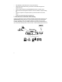
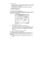
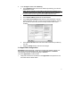
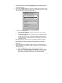
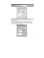
Networking the Future
PCMCIA AeroCard WPE-600
Wireless PCMCIA Card
User Manual
User Manual
WPE-600
AeroCard — Wireless PCMCIA Card
Copyright
Copyright © 2001 by Xsense Connectivity, Inc. (dba Macsense Connectivity). All rights reserved. No part
of this documentation may be reproduced in any form or by any means or used to make any directive
work (such as translation or transformation) without permission from Xsense Connectivity, Inc. Xsense
Connectivity, Inc. reserves the right to revise this documentation and to make changes in content without
obligation among Xsense Connectivity, Inc. to provide notification of such revision or change. All
products and their associated features are subject to change or upgrade at the time of the shipment or of
the sales.
FCC Notice
This equipment has been tested and found to be FCC Rules certified. These restrictions are designed to
provide protection against harmful interference from residential installations. This equipment generates
radio frequencies that may cause interference with radio communications if not used in accordance with
the instructions. Interference may even occur during proper installation. If this equipment causes
interference, the user is suggested to correct it by one or more of the following:
•
•
•
•
Reorient or relocate the receiving antenna.
Increase the separation between the equipment and receiver.
Connect the equipment into an outlet on a circuit that is separate from the one to which the
receiver is connected.
Consult the dealer or an experienced radio/television technician for help.
CE Declaration of Conformity
The equipment complies with the requirements relating to electromagnetic compatibility, the essential
protection requirement of Council Directive/EEC on the approximation of the Member States relating to
Electromagnetic compatibility.
Trademarks
All products and brand names are trademarks and/or registered trademarks of their respective
companies.
Safety Precautions
•
•
•
•
•
•
•
•
•
•
•
•
Follow all warnings and instructions marked on the product.
Slots and openings on the device are provided for ventilation. To protect it from overheating, these
openings must not be blocked or covered.
Do not use or store this product in the environment that exceeds temperature and humidity
specifications. Do not place this product near a radiator or heat register, or in a built-in installation
unless adequate ventilation is provided.
Before cleaning, unplug this product from wall outlet. Do not use liquid cleansers or aerosol
cleansers. Use a damp cloth for cleaning.
Do not place cords or cables where they may be walked on or tripped over.
Be sure to comply with any applicable local safety standards or regulations.
General-purpose cables are provided with this product. The use of any other cables or
requirements mandated by local authority is user’s responsibility.
Cables attached to devices in different locations with different power sources and grounding may
cause hazardous voltage. Consult a qualified electronic consultant before installing the product to
check if this phenomenon exists and, if necessary, take corrective action.
Never touch un-insulated telephone wires or terminals unless the line has been disconnected.
Avoid using telephone equipment or installing the product during an electrical storm.
Never install this product, or any kind of telephone jacks, lines, network cables, or power
connections in wet locations.
Never spill liquid of any kind on this product
TABLE OF CONTENTS
1.0 INTRODUCTION ........................................................................................ 3
1.1 Benefits ................................................................................................... 3
1.2 Features .................................................................................................. 3
1.3 Introduction to Wireless Networking ........................................................ 4
1.4 Wireless Network Planning ..................................................................... 5
2.0 BEFORE YOU START................................................................................ 7
2.1 Package Overview .................................................................................. 7
2.2 System and Other Requirements ............................................................ 7
3.0 MACINTOSH SETUP ................................................................................. 9
3.1 Hardware Installation of AeroCard........................................................... 9
3.2 Macintosh Driver Installation ................................................................... 9
3.3 TCP/IP Configuration............................................................................. 10
3.3.1 MacOS TCP/IP Configuration ..................................................... 10
3.3.2 Assigning TCP/IP Values Manually ............................................. 10
3.4 AppleTalk Configuration......................................................................... 11
3.5 Using the AeroCard Control Panel ........................................................ 12
3.5.1 Connecting with a Base Station................................................... 12
3.5.2 Connecting with Peer-to-Peer ..................................................... 14
3.5.3 Encryption .......................................................................................... 14
4.0 WINDOWS SETUP................................................................................... 17
4.1 Hardware Installation of AeroCard......................................................... 17
4.1.1 Windows 95/98/ME Driver Installation......................................... 17
4.1.2 Windows 2000 Driver Installation ................................................ 17
4.2 Windows Driver Installation ................................................................... 18
4.2.1 Configuring the AeroCard for Windows 95/98/Me ....................... 18
4.2.2 Configuring the AeroCard for Windows 2000 .............................. 20
4.3 TCP/IP Configuration............................................................................. 20
4.3.1 Windows 95/98/Me TCP/IP Configuration ................................... 20
4.3.2 Windows 95/98/Me TCP/IP Manual Configuration ...................... 22
4.4 Configuration Utility Program ................................................................ 24
4.4.1 Installing the Configuration Utility Program ................................. 24
4.4.2 Uninstalling the Wireless LAN Card Software ............................. 24
4.5 Using the Configuration Utility ............................................................... 24
4.5.1 Link Info....................................................................................... 25
4.5.2 Configuration............................................................................... 26
4.5.3 Encryption ................................................................................... 28
4.5.4 About ........................................................................................... 30
5.0 TROUBLESHOOTING ............................................................................. 31
5.1 Common Problems and Solutions ......................................................... 31
5.2 Frequently Asked Questions ................................................................. 34
5.3 Glossary ................................................................................................ 35
APPENDIX ..................................................................................................... 39
1.0 INTRODUCTION
Congratulations on purchasing the AeroCard, the Wireless LAN (WLAN)
PCMCIA card for Mac and PC. Welcome to the Macsense/Xsense Networking
Product Family.
These days, business moves at lightning speed. To compete, companies must
make it easy for their employees to share vital business intelligence real-time and
to collaborate without restriction. But until now, network users have been bound
by the limits of their wired network, and forced to settle for access only at their
desk.
A trend in the technology industry today is to eliminate the cable restrictions and
hassle of wires by implementing a wireless network. By choosing wireless you
reduce the hassle of cable clutter, the expensive need to run cabling in the home
or office and the aggravation altogether to crawl under that desk for the last time
to see if that Ethernet cable is connected. A WLAN standard called IEEE 802.11b
has emerged delivering speeds of up to 11 Mbps and the ability to take the
power of the Internet with you.
Imagine the ease of which you can setup this wireless network providing roaming
access to the Internet and your network. The combined flexibility of a laptop and
our Wireless card can provide some impressive changes indeed. Surf the Net
while sitting on the couch during the big Sunday game. Review your stock
portfolio in bed. Maybe the kids want to chat with friends on AOL out by the pool.
The convenience of where and when you want to connect to your network or
Internet is now yours.
1.1 Benefits
•
Eliminates the hassle and cost of cabling.
•
Longer operating range gives you more room to move around.
•
Take advantage of wireless connectivity in cafes, airports, hotels, etc.
•
Supports most Apple PowerBooks and PC notebooks with a Type II PCMCIA
slot.
•
WEP encryption provides the highest security.
•
Compatible with Apple AirPort Base Station and all 802.11b-compliant
Access Points.
•
Lifetime Free Technical Support.
•
One-Year Warranty.
1.2 Features
•
Interoperable with IEEE 802.11b (DSSS) 2.4GHz-compliant devices.
•
Up to 900 feet operating range in open environment.
•
High-speed data transfer rate of 11, 5.5, 2 and 1 Mbps
3
•
Auto-fallback to lower data rate in noisy environments.
•
WEP (Wired Equivalent Privacy) 40-bit and 128-bit data encryption for
highest security.
•
Drivers support Windows 95/98/98SE/ME/NT4/2000, and Mac OS 9.x.
•
Advanced Power Management features conserve valuable computer battery
life.
•
Supports computer-to-computer (ad-hoc) connection without an Access
Point.
•
Works with all standard Internet applications.
1.3 Introduction to Wireless Networking
There are basically two types of wireless networks: Infrastructure and Ad-hoc. An
Infrastructure network uses one or more Access Points (such as the XRouter
Aero) as a gateway, linking the wireless network to a wired LAN. As a result,
portable workstations on your wireless network have access to all the features of
your wired LAN including email, Internet access, network printers and file servers.
4
This is in contrast with another related wireless topology, called Ad-hoc network,
in which each wireless workstation communicates with one another without the
existence of an Access Point.
Although Ad-hoc allows for wireless connection between computers without an
Access Point or Wireless Router, it is Infrastructure with it’s central wireless
Access Point or Broadband Router that will be the most common.
1.4 Wireless Network Planning
Although the arrival of affordable wireless technologies has provided a great deal
of flexibility in how you connect to the Internet, there still is some needed
planning in setting up a WLAN network.
A WLAN can in some respects be considered much like a wired network with the
exception that wireless cards will transmit the data over radio frequency waves
instead of within a shielded Ethernet cable. Because of this, the initial location of
the Access Point or Wireless Router is extremely important. Situating the
AeroCard so that it has the least amount of obstruction is highly advisable.
The setup of all wireless devices involved is quite important, as they should
share the same radio channel and ESSID. Without these common settings,
they will not be able to communicate with one another. Any additional encryption
settings for security measures must be configured identically on all devices to
accept the data transfer.
One of the greatest advantages of a wireless network is the ability to roam in an
Infrastructure network. By creating multiple, yet overlapping wireless
communities, or “cells” as the industry calls it, each with their own unique
ESSID, you can allow for wireless roaming amongst clients. As you walk out of
range from one Access Point, you will be detected and picked up by another, all
the while connected to the network or Internet. This, however, does take proper
and precise planning of where to locate your Access Points and how to overlap
them so as to provide full wireless range.
Some others points to follow when planning a wireless network:
5
1.
2.
Minimize obstructions of the 802.11b RF waves
a.
Centrally locate the Wireless Router or Access Point. All obstructions
will weaken the signal to some degree.
b.
Certain building materials (metals, concrete, etc.) should be avoided by
the signal.
Situate the wireless devices so as to maximize signal output and reception
a.
Situate the WLAN devices so the signal is going straight through the
walls instead of at an angle.
b.
Stay clear (3 – 5ft.) of devices that introduce “noise” to the reception,
such as microwaves, monitors, etc.
c.
Position the antenna to maximize RF signal output.
d.
Additional Access Points can be placed in areas of low or no signal
reception.
Note: The new 802.11b wireless protocol has limitations as to how far the wireless
range can reach. Take your time to plan your wireless network properly to help
provide the best range. Each obstruction can and will diminish the signal strength.
So bare this in mind when planning and implementing your wireless network.
6
2.0 BEFORE YOU START
2.1 Package Overview
• One Wireless AeroCard
• One Driver and Utility CD-ROM
• User Manual
• Registration Card
2.2 System and Other Requirements
• A 16-bit PCMCIA Type II slot
• PCMCIA revisions 2.1 compliant card and socket services
• Mac OS 9.x; Windows 95, 98, ME, NT 4.0, or 2000
• 500 Kbytes of free disk space for utility and driver installation
7
3.0 MACINTOSH SETUP
AeroCard is compatible with the following Apple PowerBook models:
•
PowerBook 2400
•
PowerBook 3400
•
PowerBook G3 series (FireWire, Wall Street, Bronze Keyboard)
•
PowerBook G4 Titanium
And with one vacant PCMCIA Type II slot and running Mac OS 9.x. We may
support additional models in the near future so please check our website for the
current list.
3.1 Hardware Installation of AeroCard
1.
Insert the AeroCard into an available Type II PCMCIA slot with the label
facing upward and the 68-pin connector facing into the slot.
2.
Firmly push the card into the slot. Never force the card into the slot. A
generic card icon will appear on the desktop, however, this will be replaced
with the AeroCard icon once the drivers are properly installed.
3.
To properly release the AeroCard from the computer, you must first turn
“Off” the card. You can do this by opening both the TCP/IP and AppleTalk
control panels and switch them to an alternate protocol, such as PPP. Then
Close and Save the new settings and you will now be able to eject the card
by dragging the AeroCard icon to the trash.
Note: Always have the card facing correctly into the slot. Forcing the card into the
slot upside down can damage the computer.
3.2 Macintosh Driver Installation
You must first install the drivers before the OS will recognize the WPE-600
AeroCard. Supported operating systems are OS 9.x.
Note: You may use the Extension Manager to turn “off” any other wireless card
drivers, such as Apple Airport card drivers that may cause conflicts with our
wireless card.
Follow these simple steps to load the drivers properly:
1.
Double-click the Installer icon and follow the steps. This will install the
necessary drivers.
2.
Restart the computer to load these drivers.
To Disable Drivers:
1.
Under the Apple Menu, go to Extensions Manager under Control Panels.
2.
Uncheck the AeroCard Driver, AeroCard Enabler extensions and
AeroCard control panel and restart the computer.
9
To Remove Drivers:
1.
If AeroCard is currently in use, select another networking method other than
“AeroCard PC Card” in the AppleTalk and TCP/IP control panels. Close
the window and save the settings.
2.
Then manually remove the AeroCard Control Panel and AeroCard
Enabler and Driver extensions.
3.3 TCP/IP Configuration
3.3.1 MacOS TCP/IP Configuration
The AeroCard utility has a TCP/IP and AppleTalk button to link to these control
panels for proper configuration. You can either use these or open the control
panel from within the Apple Menu.
1.
Open the TCP/IP control panel.
2.
In the Connect via menu select AeroCard PC Card.
3.
In the Configure pull-down menu, select Using DHCP Server to allow
the DHCP server on the network to dynamically assign IP addressing. If
you do not have a DHCP Server, choose Manually and assign the IP
addressing.
4.
Close the TCP/IP window and save the changes.
3.3.2 Assigning TCP/IP Values Manually
If you are assigning Manual IP addresses, then you must first have valid
addresses before continuing. These might be provided by your ISP or Network
Administrator. To manage the computer’s address manually, perform the
following steps:
1.
10
In the Connect via menu select the AeroCard protocol installed in your
computer.
2.
In the Configure menu select Manually.
a.
In the IP Address field, enter the IP address provided by your network
administrator or ISP.
NOTE: No two computers on the LAN can have the same IP address or an
IP address conflict will occur. Name Server addresses must be obtained
from your ISP as we have only provided example addresses here.
b.
In the Subnet Mask field enter the valid address.
c.
In the Router Address field enter the valid address.
d.
In the Name Server Address field enter the DNS addresses in proper
order provided by your ISP. If you do not have this information, call your
ISP and ask for the Primary and Secondary Domain Name Server
numbers.
e.
In the Search Domains field enter the domain information provided by
your ISP.
f.
Close the TCP/IP window and save the changes.
3.4 AppleTalk Configuration
AppleShare allows Macintosh computers to access one another’s drives over
the network via the AppleTalk protocol. Both the AppleTalk and FileShare
control panels must be configured properly to allow this.
To access AppleShare to transfer files:
1.
Verify that the AeroCard is selected in the AppleTalk control panel and it is
associated with the Base Station.
11
2.
Verify that File Sharing is turned “On” in both computers and that the
proper resources have been shared for user access.
3.
Select “Chooser” from the Apple menu and select AppleShare to view the
available machines on the network.
4.
Choose the appropriate server to transfer files.
5.
Enter the proper username and password.
6.
Click the “OK” button. The selected server should now mount to the
desktop. You may access this mounted drive just like your own drive, with
access only allowed to properly shared folders.
3.5 Using the AeroCard Control Panel
The AeroCard is capable of two wireless networking topologies, Infrastructure
and Ad-hoc.
An Infrastructure network uses one or more Base Stations (such as the XRouter
Aero or Apple Airport Base Station) as a gateway, linking the wireless network to
a wired LAN. As a result, wireless workstations have access to all the features of
your wired LAN including email, Internet access, network printers and file
servers.
This is in contrast with another related wireless topology, called Ad-hoc network,
in which each wireless workstation communicates with one another without the
existence of a Base Station.
Note: Each wireless client must have the same ESSID as the Base Station or Adhoc network or they will not be allowed access to the wireless network.
3.5.1 Connecting with a Base Station
ESSID
All Base Stations in range will be listed in this pull-down window for operation. By
switching between these Base Stations you can see the difference in the RF
signal strength. Leaving the ESSID field empty and press Connect button will
prompt AeroCard to choose the most appropriate Base Station which is typically
the nearest.
12
To change the ESSID:
The drivers support changing the ESSID on-the-fly. You can associate to a
different Base Station by changing the ESSID. The re-association occurs
immediately and does not require a reboot.
1.
Open the AeroCard Control Panel.
2.
Select an alternate Base Station using the pull-down option or simply type in
the ESSID exactly as it is named.
3.
Click Connect to save the changes. The ESSID, MAC Address and
Signal Strength will change to reflect the new Base Station.
Base Station MAC Address
The MAC or Hardware Address of the Base Station presently in use is displayed
here in Hex format. During wireless roaming the AeroCard will choose the
nearest Base Station and will display the appropriate MAC Address.
Signal Strength
This will show the strength of the RF signal between the AeroCard and the Base
Station. This is indicative of how strong or weak the connection is due to distance
or interference such as walls, floors or other RF devices. If the signal reaches
Minimum, you may begin to notice packet loss and connection problems. Reorientate either the PowerBook or Base Station for better reception.
TCP/IP
This button opens the TCP/IP control panel for proper configuration.
AppleTalk
This button opens the AppleTalk control panel for proper configuration.
Connect
This will save your configuration settings and connect you to the Base Station
chosen.
13
3.5.2 Connecting with Peer-to-Peer
In an Ad-hoc network, each wireless workstation communicates with one
another without the existence of an Base Station. To create an Ad-hoc network,
all computers must share the same ESSID and channel. Appletalk must be
active and AeroCard is chosen in the Appletalk control panel as well as the
FileSharing control panel turned “On”.
To enable Ad-hoc:
1.
Click the box next to Enable Ad-hoc.
2.
Input the proper ESSID (case sensitive).
3.
Choose the correct Channel.
4.
Click Connect to save settings.
Note: In Ad-hoc mode, the ESSID field and signal strength will be deactivated.
3.5.3 Encryption
WEP (Wired Equivalent Privacy)
A data privacy encryption method based on a 40-bit shared key algorithm.
Note: With WEP encryption, 64-bit encryption is basically 40-bit key auto-translated
to 64-bit before being transmitted.
To enable encryption:
1.
Click the Enable Encryption box.
2.
Choose either 40-bit or 128-bit.
3.
Choose one of the four available keys and input a unique HEX key.
4.
Click OK and then Yes to save the settings.
14
This HEX key must be identical on all wireless devices to allow for proper
communication.
15
16
4.0 WINDOWS SETUP
4.1 Hardware Installation of AeroCard
1.
Insert the AeroCard into an available Type II PCMCIA slot with the label
facing upward and the 68-pin connector facing into the slot.
2.
Firmly push the card into the slot. Never force the card into the slot.
3.
To properly release the AeroCard from the computer, you must first turn “Off”
the card. You can do this with either the PC Card (PCMCIA) Status icon in
the tool bar or by opening the PCMCIA Control Panel. Then click Stop.
NOTE: Always have the card facing correctly into the slot. Forcing the card into the
slot upside down can result in severe damage to the computer.
4.1.1 Windows 95/98/ME Driver Installation
Windows automatically detects new hardware and will prompt for a driver to be
installed. Note that there are minor differences in the screen shots and
instructions but that the OS will basically walk you through the setup with the
hardware wizard. If this wizard doesn’t show up, then open the “Add/Remove
Hardware” Control Panel to begin.
1.
With the Driver CD already loaded, insert the AeroCard. Windows will detect
the card and search for but will not find the driver.
2.
Click Next when prompted then choose Search for the best driver for your
device to find the necessary driver. Click Next.
3.
On the Specify a location screen, click the Browse button to locate the
driver CD and after selecting the correct driver folder, click OK.
4.
This will return you to the Location of driver screen with the folder listed. If
the correct folder is listed, click Next.
5.
Windows may need files from the original OS CD. In this case, insert the CD
and follow the on-screen instructions to copy the necessary files to the
computer. If you are not prompted for these files, then continue with the next
step.
6.
Click Finish to begin the installation. When prompted, restart the computer.
The driver will now be installed.
4.1.2 Windows 2000 Driver Installation
1.
With the AeroCard inserted, Windows will automatically detect the new
hardware and prompt you to install the proper driver. Be sure to have the
Driver CD inserted into the CD-ROM. Click Next on the Welcome screen.
2.
Select Search for a suitable driver... and click the Next button. Windows
2000 will now search for the driver.
3.
Select Specify a location and click Next.
17
4.
Windows will now search for the driver. Click the Browse button and
navigate to the proper driver in the OS folder on the CD. Then click Next.
5.
If the Digital Signature Not Found screen appears do not be alarmed as
there is no problem. Simply click Yes to continue with the install.
6. Windows will now install the necessary driver files. Click the Finish button
when prompted. Windows may prompt you for necessary files from your
Windows 2000 CD. Insert your Windows 2000 CD if requested.
The installation is now complete. Continue on to the Configuring the AeroCard
for Windows 2000.
4.2 Windows Driver Installation
4.2.1 Configuring the AeroCard for Windows 95/98/Me
After installing the AeroCard, Windows 95, 98, or Millennium will automatically
identify the card. Next, you will need to configure the AeroCard driver software.
1.
After installing the AeroCard, the Prism adapter screen (shown below) may
automatically come up. If it does not appear automatically, click on the Start
button, choose Settings and then Control Panel. Double click on the
Network icon and choose the Prism adapter. Click the Properties button,
and then choose the Advanced tab.
Select Authentication Algorithm from the list provided and select a Value
from the drop down menu on the right. As indicated, you should always use
WECA Compliant unless you have some other reason to do so. Choose
Channel to continue or the OK button to finish. If you choose to finish now,
continue to the Installing Network Protocols section.
NOTE: For the easiest way to configure your AeroCard, please refer to the
Configuration Utility section.
18
2.
Select Channel from the list provided and select a Value, from the drop
down menu on the right, between 1 and 11. This Channel must be the same
for all wireless devices on your network. Click Network Type to continue or
the OK button to finish. If you choose to finish now, continue to the Installing
Network Protocols section.
3.
The Fragmentation Threshold Value indicates how much of the network
resources are devoted to recovering packet errors. The value should remain
at its default setting of 2,432. If you experience high packet error rates, you
can increase this value, but it will likely decrease overall network
performance. Only minor modifications of this value are recommended. Click
Network Type to continue or the OK button to finish. If you choose to finish
now, continue to the Installing Network Protocols section.
4.
Select Network Type and select a Value, from the drop down menu, of
either 802.11b Ad-Hoc, Ad-Hoc, or Infrastructure. The Infrastructure mode
allows a wireless adapter to communicate with a wired network employing
an Access Point, while the Ad-Hoc modes allow wireless-to-wireless, peerto-peer communication.
802.11b Ad-Hoc is for connecting with other Wireless Adapters that comply
with the 802.11b standard. Click Power Save Mode to continue or the OK
button to finish. If you choose to finish now, continue to the Installing
Network Protocols section.
5.
Select Power Save Mode and select either Enabled or Disabled for a
Value. Disabled will allow for uninterrupted data communication. Selecting
Enabled allows your notebook to enter “sleep” mode and could interrupt data
communication.
For further information about Power Save Mode, see the chapter entitled
Configuration Utility. Click Preamble Mode to continue or the OK button to
finish If you choose to finish now, continue to the Installing Network
Protocols section.
6.
A preamble is a signal used to synchronize the transmission timing between
two or more systems. A series of transmission pulses is sent before the data
to indicate that "someone is about to transmit data". This ensures that
systems receiving the information correctly interpret when the data
transmission tarts. The Preamble mode should be set to Long if in a “noisy”
network environment), Short (if the environment is clear), or Auto (to let the
card interpret the environment). Click OK to finish and continue to the
Installing Network Protocols section.
7.
The RTS Threshold Value should remain at its default setting of 2,432.
Should you encounter inconsistent data flow, only minor modifications are
recommended. Click ESSID to continue or the OK button to finish. If you
choose to finish now, continue to the Installing Network Protocols section.
8.
The Value for ESSID depends on what Network Type selected in item 2.
(ESSID is also commonly known as ESSID.) If the Network Type you have
chosen is "Infrastructure", it should have the same ESSID or ESSID
19
name as the Access Point. If the Network Type is "Ad-Hoc", all clients
should share the same ESSID name. Click Use WEP to continue or the OK
button to finish and continue to the Installing Network Protocols section.
9.
Select either Disabled, 40 bit, or 128 bit as the Value under Use WEP.
Wired Equivalent Privacy (WEP) is an encryption scheme used to protect
wireless data communication. The Disabled setting prevents the sharing of
data with other computers on a WEP Network. For data sharing to be
enabled, select either 40 or 128 bit encryption, depending on your needs.
For further information, see the Configuration Utility section of this guide.
Once your card is configured, click OK and continue.
4.2.2 Configuring the AeroCard for Windows 2000
After installing the AeroCard, Windows 2000 will automatically identify
the card. Next, you will need to configure the AeroCard’s driver software.
1.
From the Start Menu, select Settings and bring up the Control Panel. From
the Control Panel, double-click the Network and Dial-Up Connections
icon.
2.
At the Network and Dial-Up Connections screen, double-click the Local
Area Connection ## icon. (The number on this icon will vary with your
computer.)
3.
The General Local Area Connection Status screen will show the status of
the AeroCard connection. Click the Properties, button to continue.
4.
On the Properties screen, click the Configure button to configure your card.
5.
The next screen that you will see will be the General tab. This will give you
information on the status of the AeroCard. Click the Advanced tab to
configure your card.
6.
From this point forward, the configuration of the card is the same as for
Windows 95, 98 and Me. Follow the instructions provided in the Configuring
the AeroCard for Windows 95, 98, and ME section.
4.3 TCP/IP Configuration
Part of the process of enabling communication involves setting the IP address for
the computer. The client computer must have the IP address configured such that
it shares the same subnet-numbering scheme, as the network. We will explain
this in more detail later in the chapter. Configuring the IP address is a simple task
that can be performed through your computer’s TCP/IP control panel. We have
provided instructions for the configuration process for PC users. Find the
appropriate set of instructions in the following pages.
4.3.1 Windows 95/98/Me TCP/IP Configuration
1.
20
Double-click the Control Panel icon in My Computer folder or locate it in the
Start Menu. The sub-folder Control Panel is located under Settings.
2.
In the Control Panel, double-click the Network icon. The network interface
card (installed on your computer) appears along with the network protocol on
the Configuration list.
3.
Double-click TCP/IP protocol on the list. If TCP/IP does not appear on the
list, you must install the TCP/IP protocol first as illustrated in step 4. Clients
with TCP/IP already installed may skip to step 5.
4.
To install the TCP/IP protocol:
a.
Keep your copy of Windows 95/98/Me CD-ROM on hand. (You will
need it for this installation.)
b.
Click the Add button from the Configuration list of the Network window.
A new window appears.
c.
Double-click Protocol. Then, in the Select Network Protocol window,
choose Microsoft on the Manufacturers list, and select TCP/IP on the
right side of the list.
Follow the instructions on the screen to complete the installation process. It
should prompt for a restart and then follow on with step 5, as you will now
find a TCP/IP Protocol in your Network control panel for your wireless
adapter card.
5.
After double-clicking the installed TCP/IP protocol, the TCP/IP Properties
window appears. To automatically assign a computer’s TCP/IP, perform the
following functions:
a.
Click the IP Address tab from the TCP/IP Properties window.
b.
Select the item Obtain IP address automatically to allow the network
DHCP server, such as the XRouter Aero, to assign an IP address and
other TCP/IP configuration information to the client automatically.
21
c.
After specifying the settings of TCP/IP click OK and restart Windows to
allow the settings to take effect.
4.3.2 Windows 95/98/Me TCP/IP Manual Configuration
To manage a computer’s address manually, perform the following steps:
Click the IP Address tab from the TCP/IP properties window.
1.
Select the item Specify an IP address to allow the user to manually input a
unique IP address and Subnet Mask. (See Figure 5.1-4)
2.
In the IP Address field enter “192.168.1.x” where x is any variable of your
choice ranging from 2 to 253. Enter “255.255.255.0” in the Subnet Mask
field.
22
NOTE: No two computers on the LAN are allowed to adopt the same IP address
or an IP address conflict will occur.
3.
Click the Gateway tab and enter the Private IP Address of your router in the
Gateway IP address field and click Add. The Gateway IP address value must
be the same as the network router’s IP address to keep the proper IP
numbering scheme.
4.
Click the DNS Configuration tab, choose Enable DNS and input a unique
Host Name that simply is the computer’s name on the network. Enter the
DNS IP addresses provided by your ISP in the proper order into the DNS
Server Search Order field and click Add.
23
5.
Click OK to close out of both windows and you will be prompted to restart
the computer to activate these changes.
4.4 Configuration Utility Program
An easy-to-use management utility is provided for your AeroCard. This chapter
details the installation and usage of this utility.
4.4.1 Installing the Configuration Utility Program
1.
Insert the driver CD that accompanied your AeroCard.
2.
Open the CD and double-click on the Setup icon.
3.
The Welcome Screen for the Install Wizard will pop-up and will walk you
through the management utility installation. You will need to know the
wireless network ESSID and which mode, Ad-hoc or Infrastructure.
4.
Choose to restart your computer when prompted.
Note: You cannot have two Configuration Utilities installed at the same time. You will
be prompted to uninstall the old utility before continuing a new install.
Once installed, this utility will be represented by an icon in your tool bar. You can
also open the utility by going to Startup Menu. The icon in the tool bar indicates
signal strength by three colors:
•
Green– strong signal
•
Yellow– standard signal
•
Red– poor connection
4.4.2 Uninstalling the Wireless LAN Card Software
If you need to uninstall the Wireless LAN Card and application software for any
reason, complete the following steps:
1.
Close all programs that are currently running.
2.
Remove the Wireless LAN Card from the computer.
3.
Click the Windows Start button, point to Programs, PRISM 802.11and
then click Uninstaller.
4.
Click Yes to proceed with the software procedure. When the un-installation
is completed, click OK.
4.5 Using the Configuration Utility
Now that after the management utility is installed properly you can begin to
configure the AeroCard. Be sure to have the card inserted during configuration.
Once you open the utility you will notice that there are four tabs: Link Info,
Configuration, Encryption and About. The main tab for configuration of your
AeroCard will be Configuration but all four will be explained.
24
Note: Always use the Configuration Utility to configure your AeroCard as opposed to
going into your Network Control Panel to do so.
4.5.1 Link Info
Link Quality and Signal Strength won’t show up when the card is configured in
Ad-hoc.
State
This field will show the current status of the wireless adapter. Associated means
the adapter is linked to a wireless “cell” or “BSS”(Basic Service Set ID) and is
able to join the existing network. A status of “Not Linked” means that the node is
“Scanning” to search for an access point within range. An error message will
display if the driver cannot initialize.
Rescan
Clicking the Rescan button commands the driver to begin a new Connection
Session that acts different according to which driver mode is selected.
•
Infrastructure Mode - All available channels will be scanned continuously
until an existing Access Point is found with a matching BSS ID. It will then
proceed with authentication to associate with the found Access Point.
•
Ad-hoc Mode - The driver scans for five seconds searching for an available
Ad-hoc network, but will start its own Ad-hoc network if one is not found.
Current Channel
Displays the current channel for the active wireless connection. During
“Scanning”, this value has no relevance.
Current Tx Rate
Current Tx Rate field displays the transfer rate in megabits per second.
Throughput
25
These two fields display the instantaneous wireless Receive and Transmit
throughput displayed as measured in bytes per second. Values are updated
every two seconds.
Link Quality
The Link Quality bar indicator is only active when the driver is in Infrastructure
Mode. The link between the computer and Access Point is measured by Link
Quality. The different rating levels of link quality:
•
“Not Connected”
•
“Poor”
0 - 29
•
“Fair”
29 – 59
•
“Good”
60 - 89
•
“Excellent”
90 - 100
As “cells” must overlap to allow for wireless roaming, the AeroCard will look for
another Access Point when the driver receives a link quality rating of “Poor”. Link
Quality is a measure of receive and transmit errors over the radio.
Signal Strength
The Signal Strength bar indicator is only active when the driver is in Infrastructure
Mode. The bar graph displays normalized signal strength as reported by the
radio, averaged over all frames over 100 bytes long that are received from the
Access Point.
4.5.2 Configuration
The Configuration tab contains the majority of the operating parameter settings
for the AeroCard. Here, you will perform most of the changes needed to adapt to
different wireless networks. Changes can be applied with rebooting your
computer.
Mode
This field allows you to select from a list of supported Network “Modes”. The
modes displayed will depend on the type of installation that was performed. If an
Access Point was installed then mode will only display “AP”. If a Client installation
was done, then Mode will have two values: “Ad-hoc” and “Infrastructure”.
•
Ad-hoc - This is the 802.11 peer-to-peer mode of operation. Only one
wireless “cell” is supported for each different ESSID while in Ad-hoc mode.
Client computers communicate directly with one another with no Access
Point operating to conduct traffic.
•
Infrastructure – An 802.11 compliant Access Point conducts the packet
traffic on the network in this mode. Both wireless and wired computers are
involved in the BSS.
Note: When in Ad-hoc mode, Link Quality and Signal Strength indicators will not be
available.
26
ESSID
Similar to domains in Windows NT, the Service Set Identifier (Wireless Network
Identifier) is the group name that will be shared by every member of your
wireless network. Your client ESSID must match with that of the “Access Point”
to be a member of the wireless cell.
The ESSID can be any text string of alphanumeric characters including spaces
up to 32 characters long.
We highly recommend setting the ESSID as a unique identifier so as to not have
two wireless networks sharing the same ESSID.
To allow for wireless roaming, multiple Access Points must be placed so as to
overlap and all Access Points and wireless clients must share the same ESSID.
Tx Rate
Set to the default of “Fully Automatic”, this setting allows the user to set a
particular connection rate at which any client cannot go above.
PS Mode
Present only when the Mode is set to either Infrastructure or Ad-hoc, Access
Points, by nature, do not save power consumption.
•
Disabled – power consumption is not an option
•
Enabled – periodically, particular areas of the radio hardware are turned off
An 802.11 Access Point automatically buffers data frames for all Power Save
computers and will only send the frames if the node “Polls” for its data or
indicates that it is no longer in Power Save Mode.
Channel
Here, the user has the ability to configure the AEROCARD for up to eleven
different radio frequency channels. Only Access Points and Ad-hoc computers
can establish a wireless cell so there is no option for this in Infrastructure mode,
as they simply choose the channel of their Access Point.
If you desire to have an Ad-hoc network use a particular channel, then all
computers in the Ad-hoc network should set this parameter to the same value,
since you cannot control which member of the Ad-hoc network powers up first
and thus starts the BSS. Subsequent Ad-hoc computers will join the existing
BSS on whatever channel it happens to be on.
Only valid channels belonging to the Regulatory Domain indicated by the radio
hardware will be displayed and/or allowed.
27
Restore Defaults: Pressing this button restores each field in the panel to its
original default value. The Apply Changes button or OK must be pressed before
the default values are saved to the driver and registry.
Undo Changes: Pressing this button reverts all fields in the panel back to their
original values that were present when the Configuration Utility was opened from
the Task Bar.
Apply Changes: This button becomes active only when one of the fields has
been modified. Pressing this button applies the changed values to the driver and
saves them to the registry for the next time the PC boots up.
4.5.3 Encryption
WEP uses a 40-bit key to provide access control to your network and encryption
security for every data transmission. To decode a data transmission, each point
in a network must use an identical 40-bit key. When using 40-bit encryption,
remember that it is identical to and compatible with 64-bit encryption, but not with
128-bit. Higher encryption levels mean higher levels of security, but, due to the
complexity of the encryption, they may mean decreased network performance.
You may desire an additional measure of security on your wireless network,
which can be achieved by using WEP (Wired Equivalent Privacy) encryption.
WEP encrypts each frame transmitted from the radio using one of the Keys
entered from this panel.
When an encrypted frame is received it will only be accepted if it decrypts
correctly. This will only happen if the receiver has the WEP Key used by the
transmitter.
The 64 Bit and 128 Bit WEP keys can be generated from a user-defined Passphrase or entered manually.
Note: Please make sure that each point in your wireless network is set at an identical
WEP value.
28
Pass-Phrase
Alternatively a Pass-phrase can be entered which is used as a “constant
variable” to randomly generate the four keys. This saves considerable time since
the same keys must be entered into each node on the wireless network. The
Pass-phrase can be any text string with a maximum of 31 alphanumeric
characters and is strongly recommended because it is the easiest way to
generate WEP keys.
To enable WEP and generate a valid encryption key:
1.
Choose 64 Bit or 128 Bit in the pull-down menu.
2.
Type the exact, case-sensitive Pass-phrase into the field.
3.
Click the “Apply Changes” button to generate the four keys.
4.
Click “OK” to finish.
Note: The WEP key must be the same for both the sending and receiving machines.
(Although you may need to enter keys manually to satisfy the needs of your
particular network, we recommend implementing the Pass-phrase feature when
you can for simplicity. Check encryption settings on other computers to verify that
your settings are correct.)
Key 1 through Key 4
These four fields can be used to manually enter the keys. This may be
necessary if you wish this node to match keys in a different vendor’s product.
These fields also display the keys when they are generated using a Pass-phrase.
Default Tx Key
This pop-up field sets which of the four keys will be used by the driver to encrypt
frames it will be transmitting. This field does not affect decryption, as the driver
can decrypt any frame that it receives which was encrypted with one of the four
keys.
29
Note: The 128-bit encryption is limited to only one key and therefore, the Default Tx
Key is not available.
Apply
Clicking Apply will save the newly generated keys in the driver registry until they
are replaced.
Note: Please make sure that each point in your wireless network is set at an identical
WEP value. WEP 64-bit encryption is not upward compatible with 128-bit devices.
4.5.4 About
The About screen shows the release information for the Driver Version,
Configuration Utility Version and Firmware Version.
30
5.0 TROUBLESHOOTING
This chapter provides solutions to problems that may occur during the installation
and operation of the AeroCard. Check the following symptoms and their possible
causes before contacting Xsense Tech Support. Read the description below to
solve your problems. If you can’t find an answer here, check the
Macsense/Xsense website at www.macsense-usa.com.
5.1 Common Problems and Solutions
My PowerBook can’t see other computers in AppleShare.
•
Verify that AppleTalk is “active” and the AeroCard is chosen and that File
Sharing is configured properly.
•
Double-check the other computer as well and make sure that both
computers are using the exact settings for ESSID and Encryption.
My PowerBook doesn’t recognize the AeroCard.
•
Verify that the AeroCard is firmly inserted into the PCMCIA slot.
•
Verify whether the AeroCard shows in either TCP/IP or AppleTalk.
•
Check to see if the drivers are loaded properly.
•
Re-install the drivers and re-insert the AeroCard.
My computer does not recognize the AeroCard.
•
Verify that the AeroCard is properly inserted into the PCMCIA slot. The card
should be inserted with the sticker facing upward and the antenna portion
facing outward.
•
Verify that the drivers are loaded properly.
The AeroCard does not work properly.
•
Reinsert the AeroCard into your notebook’s PCMCIA slot. A beep should be
heard if the adapter is properly inserted.
•
For Mac environments, make sure that a PCMCIA card service driver is
installed in your computer.
•
Open the PC Card Control Panel. If the card is detected, it should be listed
here and is working properly. If you see a yellow question mark, the
resources are conflicting. Right click on My Computer and select Properties.
Select the device manager and click on the Network Adapter. You will find
the AeroCard if it is installed successfully. If you see the yellow exclamation
mark, the resources are conflicting. Click on PCMCIA card and then on
PCMCIA card service. You will see the status of the AeroCard. If there is a
yellow question mark, please check the following:
Tips to follow if the card isn’t working properly:
•
Does your notebook support a 3.3V card?
•
Does your notebook have a free IRQ (PC only)?
31
•
Did you install the card and driver correctly?
If the AeroCard does not function after attempting the above steps, remove the
card and do the following:
•
Uninstall the driver software.
•
Restart your laptop/PowerBook and repeat the hardware and software
installation steps as specified in this User Manual.
While in Infrastructure Mode, I cannot communicate with the other
computers connected via Ethernet.
•
Verify that the Notebook/PowerBook with the AeroCard is turned on.
•
Verify that your AeroCard is communicating over the same channel and with
the same WEP security settings as the other computers in the Infrastructure.
I suspect the AeroCard is disrupted by interference.
You may be able to eliminate any interference by trying the following:
•
Reseat the Wireless LAN Card.
•
Increase the distance between the wireless computers and the device
causing the radio interference.
•
Plug the computer equipped with the Wireless LAN Card into an outlet on a
different branch circuit from that used by the affecting device.
•
Keep the computer with the Wireless LAN Card away from the microwave
oven, power supplies and large metal objects.
•
Consult the dealer or an experienced radio technician for help.
The AeroCard is not detected.
If the Wireless LAN Card is not detected by Windows, try the following:
•
Incorrect ESSID. Make sure the ESSID is the same for all computers that
have a Wireless LAN Card.
•
Changes are not being recognized by your computer. Restart your computer.
•
If in Ad-hoc mode, make sure the Log on to Windows NT domain check box
is not selected in the Client for Microsoft Networks Properties dialog box in
the Network Configuration tab.
•
Incorrect IP Address or Subnet Mask. Check these settings in the TCP/IP
Properties dialog box in the Network Configuration tab.
•
Make sure the channel for the Wireless LAN Card is set to the same channel
number as the one for the other Wireless LAN card you are trying to
connected to.
Cannot connect to another wireless LAN card.
If you cannot make a connection to another Wireless LAN Card from your
computer, it could be due to one of the following reasons:
•
32
Make sure the Wireless LAN Card is properly inserted in the PCMCIA slot.
•
Make sure the PCMCIA slot in your computer is working.
•
Contact your dealer for additional testing if there is a hardware problem with
the Wireless LAN Card or call our Technical Support line.
33
5.2 Frequently Asked Questions
Can applications be run from a remote computer over the wireless
network?
The application itself must support running over the network.
Can I play computer games with other members of the wireless network?
The game must support multiple players over a LAN (local area network).
What is IEEE 802.11 standard?
The IEEE 802.11 WLAN standards subcommittee is developing this standard for
the industry. The objective is to enable WLAN hardware from different
manufacturers to communicate. The 802.11 and 802.11b specifications apply to
wireless Ethernet LANs, and operate at frequencies in the 2.4-GHz region of the
radio spectrum.
What IEEE 802.11 features are supported?
The product supports the following IEEE 802.11 functions:
• CSMA/CA plus Acknowledge protocol
• Automatic Rate Selection
• Multi-Channel Roaming
• Power Management
• RTS/CTS feature
• Fragmentation
Can Wireless products support printer sharing?
Wireless products perform the same function as LAN products. Therefore,
Wireless products can work with Windows NT/2000, or other LAN operating
systems to support printer or file sharing.
What is DSSS? What is FHSS? And what are their differences?
Frequency-Hopping Spread-Spectrum (FHSS) uses a narrowband carrier that
changes frequency in a pattern that is known to both transmitter and receiver, but
not an unintended receiver. Direct-Sequence Spread-Spectrum (DSSS)
generates a redundant bit pattern for each bit to be transmitted. Even if one or
more bits in the chip are damaged during transmission, statistical techniques
embedded in the radio can recover the original data without -the need for
retransmission. To an unintended receiver, DSSS appears as low power
wideband noise and is rejected (ignored) by most narrowband receivers.
Would the information be intercepted while transmitting on air?
WLAN features two-fold protection in security. On the hardware side, as with
Direct Sequence Spread Spectrum technology, it has the inherent security
feature of scrambling. On the software side, WLAN series offer the encryption
function (WEP) to enhance security and Access Control. Users can set it up
depending upon their needs.
34
5.3 Glossary
Access Point
An internetworking device that seamlessly connects wired and wireless networks.
Access Points combined with a distributed system support the creation of
multiple radio cells that enable roaming throughout a facility. In Macintosh terms,
Access Point is also referred to as Base Station.
Ad-hoc
An ad-hock network is a local area network or other small network, such as
wireless, in which some of the network devices are part of the network only for
the duration of a communications session. In the case of mobile and portable
devices, they can be a part of the network when in close proximity to the rest of
the network.
BSS ID (Basic Service Set)
BSS Basic Service Set. A set of stations controlled by a single
coordination function.
Cable Modem
A device that connects your PC to a local TV line and receives data at 1.5Mpbs.
One of its connections is connected to your PC and the other one is to the cable
wall outlet. It attaches a standard 10BASE-T Ethernet card to a computer and
modulates between digital and analog signals.
Cell
The radio coverage area for a wireless device to communicate with a base
station. The size of the cell can depend on the antenna, the speed of
transmission, and the physical area.
Channel
Each channel refers to a different frequency level allowing for multiple
communication paths through one device, much the same way a radio operates.
ESS ID (Extended Service Set)
One of three IEEE 802.11 basic topology schemes. ESS WLAN configurations
consist of multiple BSS cells that can be linked by either wired or wireless
backbones. IEEE 802.11 supports ESS configurations in which multiple cells use
the same channel, and configurations in which multiple cells use different
channels to boost aggregate throughput.
Dynamic IP address
A dynamic IP address is an IP address that is given out automatically from a
DHCP Server to client computers or routers on a LAN or WAN.
Gateway
An entrance to a network. It associates with both router and switch whereas the
router gives direction as data arrives at the gateway and the switch, on the other
hand, furnishes its actual path in and out of the gateway.
35
IEEE
Abbreviation of Institute of Electrical and Electronics Engineers. Founded in
1884, the IEEE is an organization composed of engineers, scientists, and
students. The IEEE is best known for developing standards for the computer and
electronics industry. In particular, the IEEE 802 standards for local area networks
are widely adopted.
IEEE 802.11 Standard
In WLAN technology, 802.11 refers to standards set by the Institute of Electrical
and Electronics Engineers. There are three specifications in the family, 802.11,
802.11a and 802.11b. 802.11 and 802.11b refer to wireless Ethernet LANs and
operate at frequencies around the 2.4 GHz range. 802.11 generally have data
speeds of 1 or 2 Mbps while 802.11b can have speeds of 5.5 or 11 Mbps.
802.11b can also realize speeds up to 20 Mbps. 802.11a refers to wireless ATM
systems and operates at frequencies between 5 to 6 GHz.
Infrastructure
This type of network is a wireless or other type of small network where the
wireless network devices are made a part of the network through the use of an
Access Point. The Access Point connects the device to the rest of the network.
IP Address
An identifier for a computer or device on a TCP/IP network. Networks using the
TCP/IP protocol route messages base on the IP address of the destination. The
format of an IP address is a 32-bit numeric address written as four numbers
separated by periods. Each ranges from 0 to 255. For example, 157.124.10.1
could be a valid IP address.
ISM band
The FCC and their counterparts outside of the U.S. have set aside bandwidth for
unlicensed use in the ISM (Industrial, Scientific and Medical) band. Spectrum in
the vicinity of 2.4 GHz, in particular, is being made available worldwide. This
presents a truly revolutionary opportunity to place convenient high-speed
wireless capabilities in the hands of users around the globe.
ISP (Internet Service Provider)
An organization that provides access to the Internet. Small ISPs provide
service via modem and ISDN while the larger ones also offer private line
hookups (T1, fractional T1, etc.).
LAN (Local Area Network)
A computer network that spans a relatively small area. Most LANs are confined
to a single building or a group of buildings. However, one LAN can be connected
to other LANs over any distance via telephone lines and radio waves. A system
of LANs connected this way is called a wide-area network (WAN)
MAC Address (Media Access Control Address)
On a network, it is a unique 48-bit number used in Ethernet data packets to
36
uniquely identify an Ethernet device, such as an Ethernet adapter.
Optional WEP40
A variation of WEP 40 that allows for the receipt and transmission of both WEP
40 encrypted packets and non-encrypted packets.
PCMCIA (Personal Computer Memory Card International Association)
This Association develops standards for PC cards, formerly known as
PCMCIA cards. These cards are available in three types, and are about
the same length and width as credit cards. However, the different cards
range in thickness from 3.3 mm (Type I) to 5.0 mm (Type II) to 10.5 mm
(Type III). These cards can be used for various functions, including
memory storage, landline modems, and wireless modems.
Protocol
A set of rules that end points in a telecommunication use as they communicate.
These end points must recognize and observe the protocol in the
communication.
Radio Frequency
Terms: GHz, MHz, Hz —The international unit for measuring frequency is Hertz
(Hz), equivalent to the older unit of cycles per second. One megahertz (MHz) is
one Million-Hertz. One gigahertz (GHz) is one Billion-Hertz. The standard U.S.
electrical power frequency is 60 Hz, the AM broadcast radio frequency band is
0.55–1.6 MHz, the FM broadcast radio frequency band is 88–108 MHz, and
wireless 802.11 LANs operate at 2.4GHz.
Roaming
The ability to use a wireless device and move from one access point’s range to
another access point without a drop or loss of connection.
Shared Key Algorithm
In encryption, both the sender and the recipient use the same secret key to both
encode and decode a message.
Spread Spectrum
Spread Spectrum technology is a wideband radio frequency technique developed
by the military for use in reliable, secure, mission-critical communications
systems. It is designed to trade off bandwidth efficiency for reliability, integrity,
and security. In other words, more bandwidth is consumed than in the case of
narrowband transmission, but the trade off produces a signal that is, in effect,
louder and thus easier to detect, provided that the receiver knows the parameters
of the spread-spectrum signal being broadcast. If a receiver is not tuned to the
right frequency, a spread-spectrum signal looks like background noise.
SSID (Service Set ID)
A group name shared by every member of a wireless network. Only client PCs
with the same SSID are allowed to establish a connection.
37
Static IP address
A static IP address is an IP address that does not change and is manually set in
client computer or router in a LAN or WAN.
TCP/IP
Acronym for Transmission Control Protocol/Internet Protocol, the basic protocol
of the Internet, which can be used as a communications protocol in a private
network. Every computer that has direct access to the Internet has a copy of the
TCP/IP program. TCP/IP uses the client/server model in which the user is the
client that requests and is provided service by another computer, which is the
server on a network. HTTP, FTP, Telnet, SMTP and other protocols are often
packaged with TCP/IP as a “suite” in order to get to the Internet.
URL
A URL (Uniform Resource Locator) is the address of a file (resource) accessible
on the Internet. The URL contains the name of the protocol required to access
the resource, a domain name that identifies a specific computer on the Internet,
and a hierarchical description of a file location on the computer.
WLAN
A WLAN in which a user can connect to a network using a wireless connection.
IEEE 802.11 specifies the technology for WLANs, as well as the Wired
Equivalent Privacy algorithm encryption method.
WEP (Wired Equivalent Privacy)
A data privacy encryption method based on a 64-bit shared key algorithm.
WEP Key
A form of security and encryption used for WEP. It is a special sequence of
characters used to restrict access to a wireless network.
WEP40
A 40-bit encryption method that secures data packets over an insecure path,
such as the Internet, whereby the recipient must use a matching 40-bit key to
decrypt the data.
38
APPENDIX
SPECIFICATIONS:
Frequency Band: 2400-2483.5 MHz (subject to local regulations).
Number of Selectable Channels: 11 (USA and Canada)
Modulation Technique: Direct Sequence Spread Spectrum (DSSS); CCK
(11Mbps, 5.5Mbps), DQPSK (2Mbps), DBPSK (1Mbps).
Spreading: 11-chip Barker sequence
Media Access Protocol: CSMA/CA (Collision Avoidance) with ACK
Security: 40-bit, 128-bit WEP Encryption
Interface: PCMCIA Type II 3.3V
Visible Indicator: One Red LED for Power Indication, One Green LED for
Transmission Activity
Antenna Type: 1 Internal On-board 3D Antenna
Frame Error Rate (FER): Less than 8%
Receiver Sensitivity (FER<8%): -80dBm@11Mbps (Normal temperature)
Available Distance:
11 Mbps
Open Space
5.5 Mbps
2 Mbps
1 Mbps
984ft/300m 1476ft/450m 1969ft/600m 2133ft/650m
Semi Open Space
197ft/60m
263ft/80m
329ft/100m
394ft/120m
Closed Space
115ft/35m
148ft/45m
197ft/60m
197ft/60m
Average Output Power: 10dBm
Average Power Consumption: RX mode: 200mA; TX mode: 270mA
Operation Temperature Range: 32-131°F (0-55°C) 80% max. humidity (no
condensation)
Storage Temperature Range: 14-149°F (10-65°C) 80% max. humidity (no
condensation) allowed)
OS Compatibility: Windows 95/98/98SE/ME/NT4/2000; Mac OS 9.x
Supported PowerBook Models: PowerBooks 2400 and higher with PCMCIA
slot.
Electromagnetic Emission: FCC Class B; CE Mark Commercial.
Standards & Interoperability: IEEE 802.11b, Wi-Fi of WECA
Dimensions (LxWxH): 4 5/8 x 2 1/8 x 1/2 in. (118 x 54 x 11 mm)
Weight: 1.6oz (46g)
39
XSENSE STANDARD LIMITED WARRANTY
Xsense warrants the product against any defects in manufacturing for the
warranty period. If you require warranty service, be sure to have your proof of
purchase and a barcode from the product packaging on hand when calling.
Warranty service cannot be processed without proof of purchase.
Xsense cannot offer direct refunds for any product purchased in the retail
channel. Proper refund must be done through the retail channel where the
product was purchased. In no event shall Xsense’s liability exceed the price paid
for the product from direct, indirect, special, incidental, or consequential damages
resulting from the use of the product, its accompanying software, or its
documentation.
Xsense offers cross shipments, a faster process for processing and receiving
your replacement. Xsense pays for UPS Ground only. All customers located
outside of the United States of America and Canada shall be held responsible for
shipping, custom duties, and handling charges. Please call Xsense Tech Support
for more details.
40
180-00339-000