1
User ’s Manual
LG Programmable Logic Controller
Computer Link Module
MASTER-K
K7F-CUEA
K4F-CUEA
K3F-CU2A
K3F-CU4A
L G Industrial Systems
Chapter 1 Introduction
1 Introduction ............................................................................................... 1-1
Chapter 1
MASTER-K
Introduction
1 Introduction
This manual describes the computer link (Cnet) system of MASTER-K series. The Cnet network
system means PLCs of network communicate through the computer link module.
The MASTER-K Cnet module has following features;
A frame editor software that are based on MS-Windows 95/98 is provided. User can
write an user-defined protocol for communication with other manufacturer’s PLCs.
Supports RS-232C and RS-485 channels and they can operate stand-alone mode or
interlocking mode.
A 128kbyte flash memory is equipped for user protocol data storage.
Supports a LGIS’s dedicated protocol for easy and simple setup of the network between
LGIS products such as PMU.
Supports a multi-drop function that maximum 32 station can be joined into a network.
With a built-in modem communication function, it can control a remote PLC by dedicated
protocol, KGL-WIN connection, or user-defined protocol.
Supports various communication speed (baud rate) from 300bps to 153,600bps (RS422)
RS-422 channel provides 1:1, 1:N, or N:M communication modes.
Full duplex (RS-422) and half-duplex (RS-485) are available.
In a main base board, multiple Cnet modules can be mounted. (K200S : 2 modules,
K300S : 4 modules, K1000S : 8 modules)
Provides powerful self-diagnosis functions and loop-back test function.
1-1
Chapter 1
MASTER-K
Introduction
The following table shows communication modules of MASTER-K series. Please refer the table
when configure a MK network system.
Network
type
Master / Slave
Master (FMM)
Catalog
number
Applicable PLC system
K3F-FUEA
K200S
K4F-FUEA
K300S
K7F-FUEA
K1000S
G0L-FUEA
IBM compatible PC
K7F-FUOA
K1000S
K3F-RBEA
K200S
K4F-RBEA
K300S
K7F-RBEA
K1000S
G0L-SMxA
Stand-alone
Optical fiber
K7F-RBEA
K1000S
Twisted pair
G0L-FREA
Stand-alone
Optical / twisted pair
G0L-FEOA
Stand-alone
K3F-CU2A
K200S
K3F-CU4A
K200S
K4F-CUEA
K300S
K7F-CUEA
K1000S
Cable type
Twisted pair
Optical fiber
MK Fnet
Slave (FSM)
Option (FOU)
MK Cnet
Twisted pair
Master / slave Twisted pair
(selectable)
or RS-232C cable
Remark
1. There is a limitation on the maximum module numbers that are mountable on a base
board. Refer the following table for details
Module type
Fnet
Cnet
K200S
Max. 2 modules
Max. 2 modules
K300S
Max. 4 modules
Max. 4 modules
K1000S
Max. 4 modules
Max. 8 modules
2. Communication modules can be mounted on main base board only.
3. Master/slave can be selected with parameter setting.
1-2
Chapter 2 Terminology
2 Terminology ............................................................................................... 2-1
2.1.1 Communication methods .......................................................................................2-1
2.1.2 Transmission type ..................................................................................................2-1
2.1.3 Asynchronous transmission ...................................................................................2-2
2.1.4 Protocol ..................................................................................................................2-3
2.1.5 BPS / CPS..............................................................................................................2-3
2.1.6 Node .....................................................................................................................2-3
2.1.7 Packet ....................................................................................................................2-3
2.1.8 Port
.....................................................................................................................2-3
2.1.9 RS-232C.................................................................................................................2-3
2.1.10RS-422/485 ............................................................................................................2-4
2.1.11 BCC .....................................................................................................................2-4
2.1.12KGL-WIN function ..................................................................................................2-4
2.1.13Frame .....................................................................................................................2-5
Chapter 2
MASTER-K
Terminology
2 Terminology
This chapter will describe the meaning of terms used in this manual.
2.1.1
Communication methods
1) Simplex
This is a communication type that the data is transmitted with a fixed direction. It is not
allowed to move data in reverse direction.
2) Half-duplex
It is available to move data in both directions. However, data transference in a direction
should be done after another direction transference is completed because two-way
transmissions share a common communication cable.
3) Full-duplex
Data is transmitted in two-way directions with two communication cables.
2.1.2
Transmission type
The transmission type can be divided into two types in consideration of binary (bit
composed 0 and 1) transmission speed, reliability, and economy.
1) Serial transmission
In serial transmission type, each bits of data is transmitted in order through single cable.
Its transmission speed is slow, but it provides lower installation cost and simpler software.
RS-232C, RS-422, and RS-485 are typical serial transmission types.
Receive
Transmission
76543210
76543210
2-1
Chapter 2
MASTER-K
Terminology
2) Parallel transmission
In parallel transmission, 8bits (1byte) are transmitted at once through 8 communication
lines. It provides faster transmission speed, and higher communication reliability, but
installation cost are increased in geometrical series by transmission distance.
1
Transmission
0
Receive
1
1
0
0
1
0
2.1.3
Asynchronous transmission
With the asynchronous transmission, there is no clock signal for timing synchronization.
Data is divided in a character (7 or 8 bits) and start/stop bits are added at the top/bottom
of character. Then each characters with start/stop bits are transmitted in order.
Example) The transmission of ‘KOREA’
START
ENQ(h05)
STOP
PARITY
K
START
STOP
PARITY
O
2-2
START
STOP
PARITY
START
R
STOP
PARITY
START
E
STOP
PARITY
START
A
STOP
PARITY
START
EOT (h04)
STOP
PARITY
Direction of transmission
Chapter 2
2.1.4
MASTER-K
Terminology
Protocol
This is a rule that specifies how two or more devices communicate more efficiently and
reliably. Generally, it defines following features;
2.1.5
Establishment of communication
Connection between devices
The structure of data exchange format
Re-transmission when an error occurred
Switching transmit/receive
Character synchronization between devices
BPS / CPS
The BPS and CPS stand for ‘Bit Per Second’ and ‘Character Per Second’. The BPS/CPS
show how many bits / characters can be transferred in a second. Because a character is
consist of 8 bits, in general, the CPS shows how many bytes can be transferred in a
second.
2.1.6
Node
It indicates a point that a data line is branched into two or more lines in the network tree
structure. Generally, a network consists of multiple nodes. Also, the term ‘station’ has
same meaning.
2.1.7
Packet
It is a compound word of ‘package’ and ‘bucket’ and a data transmission unit of a ‘packet
exchange system’. In this system, the data is divided into a specific length unit, and a
header is added. A ‘header + divided data’ is called as a packet.
2.1.8
Port
A port means a data input/output gate of data transmission devices. In Cnet serial
communication, a port means RS-232C or RS-422/485 port.
2.1.9
RS-232C
RS-232C is one of serial communication standards that are established by EIA. It defines
the communication interface between modem and a computer (or other devices), and it
can be used for direct connection without modem (null-modem). The demerit of RS-232C
is that a transmission distance is short and only 1:1 connection is possible.
2-3
Chapter 2
MASTER-K
Terminology
2.1.10 RS-422/485
It is a standard of serial communication that is made up for demerits of RS-232C standard.
It supports long transmission distance and 1:N connection. The difference of RS-422 and
RS-485 is the number of signal lines. The RS-422 has 4 signal lines such as TX(+), TX(-),
RX(+), and RX(-), and RS-485 has 2 signal lines (+ and –). Because of transmit and
receive line is separated, RS-422 can perform full-duplex communication, but the RS-485
performs half-duplex communication because transmit and receive share one signal line.
2.1.11 BCC
The BCC stands for ‘Block Check Character’. To check a transmitting data contains error
or not, a transmitting station calculates BCC from data and adds the BCC at the bottom of
data. Then, the receiving station can determine whether an error occurred by comparing
the BCC with transmitted data.
2.1.12 KGL-WIN function
In the MASTER-K Cnet network, user can control (program read, write, monitor and
debugging) a remote PLC through a Cnet network as if the remote PLC is connected to
KGL-WIN directly. Especially, a PLC at the far-away place can be controlled with a
modem connection. However, only 1stage remote connection is available.
KGLWIN
KGLWIN
MODEM
RS-232C
Physical connection
Physical connection
MODEM
PLC A
CPU
PLC B
Cnet
CPU
2-4
Cnet
Chapter 2
MASTER-K
Terminology
2.1.13 Frame
The frame is a structure definition of data transmission. It consists of a segment (station
number, instruction, structured data, and/or execution result), control code for
synchronization, parity bit, and BCC for error detection. The frame of MASTER-K Cnet is
as following picture.
Segment
Tail
Execution result
Response frame
Header : An ASCII code that indicates the start of frame
Tail
: An ASCII code that indicates the end of frame
Parity
: It is a bit used for an error detection of a byte
BCC
: It is a byte used for an error detection of a frame
2-5
Tail
BCC
Segment
ETX
Instruction
ACK
Header
Station No
Header
BCC
Structured data
EOT
Instruction
Station No
ENQ
Request frame
Chapter 3 Specifications
3 Specifications ............................................................................................ 3-1
3.1 General specifications ..............................................................................................3-1
3.2 Performance specifications .....................................................................................3-2
3.3 Parts names and descriptions .................................................................................3-3
3.3.1 K3F-CU2A ..............................................................................................................3-3
3.3.2 K3F-CU4A ..............................................................................................................3-4
3.3.3 K4F-CUEA..............................................................................................................3-5
3.3.4 K7F-CUEA..............................................................................................................3-6
3.4 Cable specifications..................................................................................................3-7
3.5 Terminal resistor........................................................................................................3-8
3.5.1 RS-422 network......................................................................................................3-8
3.5.2 RS-485 network......................................................................................................3-8
Chapter 3
MASTER-K
Specifications
3 Specifications
3.1 General specifications
The following table shows the general specifications of MASTER-K series.
No
1
2
3
4
Item
Specifications
Remark
Operating ambient
0 ~ 55 (32 ~ 131 °F)
temperature
Storage ambient
temperature
-25 ~ 70 (-13 ~ 158 °F)
Operating ambient
5 ~ 95%RH,
humidity
Storage ambient
humidity
non-condensing
5 ~ 95%RH,
non-condensing
Occasional vibration
5
Vibration
resistance
Frequency
Acceleration
Amplitude
10f<57 Hz
-
0.075 mm
57 f150 Hz
9.8 (1G)
-
Sweep count
10 times in each
direction for X, Y, Z
IEC 1131-2
Continuos vibration
Frequency
Acceleration
Amplitude
10f<57 Hz
-
0.035 mm
57f150 Hz
4.9 (0.5G)
-
10 times in each
direction for X, Y, Z
Maximum shock acceleration: 147 (15G)
6
Shock resistance
Duration time :11 ms (3 times in each of X, Y and Z directions)
IEC 1131-2
Pulse wave: half sine wave pulse
Square wave
impulse noise
Electrostatic
discharge
7
Noise immunity
1,500 V
LGIS ’ s
specification
Voltage :4 kV(contact discharge)
IEC 1131-2
IEC 801-2
Radiated electro27 ~ 500 MHz, 10 V/m
magnetic field
Fast transient
burst noise
IEC 1131-2
IEC 801-2
Severity All power Digital I/O
Level modules ( Ue ≥ 24 V)
Voltage
8
Atmosphere
Free of corrosive gases
9
Altitude for use
Up to 2,000m ( 6,560ft )
10
Pollution degree
2
11
Cooling method
Self-cooling
2 kV
1 kV
Digital I/O (Ue<24 V)
IEC 1131-2
Analog I/O
Communication I/O IEC 801-4
0.25 kV
Remark
1. IEC (International Electrotechnical Commission) : The international civilian organization which
produces standards for electrical and electronics industry.
2. Pollution degree : It indicates a standard of operation ambient pollution level. The pollution
degree 2 means the condition in which normally only non-conductive pollution occurs.
Occasionally, however, a temporary conductivity caused by condensation shall be expected
3-1
Chapter 3
MASTER-K
Specifications
3.2 Performance specifications
The following table shows the performance specifications of MASTER-K Cnet modules.
Items
Specifications
Serial communication
channel
RS-232C
Modem function
Operation modes
Data structure
RS-422/485
Comply with RS-232C standards, 1 channel
1)
Comply with RS-422/485 standards, 1 channel
Long-distance remote communication with external device is possible
via a public telephone line by connecting a modem to Cnet module.2)
Dedicated
protocol
Supports multi-drop and 1:1 connection. (Dedicated
protocol for LGIS’s products)
KGL-WIN
protocol
Supports a connection with KGL-WIN and remote
PLC control (program read, write, monitor, and
debug)
User-define
protocol
Supports a user-defined protocol written by a frame
editor.
Data bit
7 or 8
Stop bit
1 or 2
Parity
Even / Odd / None
Set with the basic
parameter of frame editor 3)
Channel selection
Stand-alone / Interlocking (set with operation mode switch) 4)
Synchronization
Asynchronous
Baud rate
300 ~ 153,600 bps (set with the basic parameter of frame editor) 5)
Station number
Max. 32 stations (0 ~ 31), Set with the basic parameter of frame editor
Transmit distance
Diagnosis functions
Current consumption
RS-232C
Max. 15m
RS-422/485
Max. 500m
Loop-back self-diagnosis function
Indicates operation status by 16 LEDs (K200S : 8 LEDs)
Max. 100mA
Remark
1) RS-422 and RS-485 can be selected with the basic parameter of frame editor.
2) To use modem function, set the ‘type’ of basic parameter as ‘dial-up modem’ or ‘dedicated
modem’ in frame editor.
3) In stand-alone mode, RS-232C and RS-422/485 channels can have different data structures.
4) It is not allowed to change operation mode while the Cnet module is operating.
5) Only RS-422/485 channel of K300S/1000S Cnet version 1.3 (or later) can be use 76,800 and
153,600 bps. The maximum baud rate of K200S is 38,400.
3-2
Chapter 3
MASTER-K
Specifications
3.3 Parts names and descriptions
3.3.1
K3F-CU2A
RUN
TX
RX
ACK
NAK
COM-ERROR
MODEM
SYS-RUN/ERR
No
Name
LED displaying
section
Indication of operating
status of K3L-CU2A(see
Appendix A1)
Mode switch
Setting
of
operation
mode(see 4.1)
Connector
RS-232C
Connector RS-232C for
connection with external
devices
K3F - CU 2 A
MODE
RS-232C
Contents
3-3
Chapter 3
3.3.2
MASTER-K
Specifications
K3F-CU4A
RUN
TX
RX
ACK
NAK
COM-ERROR
RS-485
SYS-RUN/ERR
Name
No
LED displaying
section
Indication of operating
status of K3F-CU4A(see
Appendix A)
Mode switch
Setting of operation
mode(see 4.1)
Connector
RS-422/485
Connector RS-232C for
connection with external
devices
K3F - CU 4 A
MODE
Contents
RS-422/485
3-4
Chapter 3
3.3.3
MASTER-K
Specifications
K4F-CUEA
K4F-CUEA
RUN/BPS
TX/BPS
RX/BPS
ACK/DATA
NAK/PARITY
ERR/EVEN-ODD
MODEM/STOP
SYS-RUN
RS-232C
RUN/BPS
TX/BPS
RX/BPS
ACK/DATA
NAK/PARITY
ERR/EVEN-ODD
RS-485/STOP
SYS-RUN
RS-422
No.
DISPLAY
MODE
RS-232C
RDB
SD
SD
SG
FG
3-5
Contents
Indication of operating status
of K4F-CUEA(see Appendix
A1)
Display
switch
Switch for indication of
parameter and station number
(see Appendix A1)
Mode switch
Setting of operation mode(see
4.1)
Connector
RS-232C
Connector RS-232C for
connection with external
devices
Connector
RS-422/485
Connector RS-422/485 for
connection with external
devices
RS-422
RDA
Name
LED
displaying
section
Chapter 3
3.3.4
MASTER-K
Specifications
K7F-CUEA
K7F-CUEA
RS-232C
RS-422
RUN/BPS
TX/BPS
RX/BPS
ACK/DATA-BIT
NAK/PARITY
ERR/EVEN-ODD
MODEM/STOP-BIT
SYS-RUN
Name
Contents
LED displaying
section
Indication of operating status
of K7F-CUEA(see Appendix
A1)
Display switch
Switch for indication of
parameter
and
station
number (see Appendix A1)
Mode switch
Setting
of
mode(see 4.1)
Connector
RS-232C
Connector
connection
devices
Connector
RS-422/485
Connector RS-422/485 for
connection with external
devices
RUN/BPS
TX/BPS
RX/BPS
ACK/DATA-BIT
NAK/PARITY
ERR/EVEN-ODD
RS-485/STOP-BIT
SYS-RUN
DISPLAY
No.
MODE
RS-232C
RS-422
RDA
RDB
SDA
SDB
SG
FG
3-6
operation
RS-232C
for
with external
Chapter 3
MASTER-K
Specifications
3.4 Cable specifications
When communicate with RS-422 or RS-485 channel, twisted pair cable should be used in
consideration of transmit distance and speed. The following table shows the recommended
cable specification of communication cable. Please make sure use the recommended cable or
equivalent cable complying with the following specifications.
! Type
: Low capacitance LAN interface cable
! Catalog number
: LIREV-AMESB
! Specification
: 2P × 22AWG ( D / 0.254 TA )
! Manufacturer
: LG Cable Co. Ltd.
1) Electrical characteristics
Item
Unit
Characteristic
Conductor resistance
Ω / km
Dielectric strength
V / 1 min
Stands 1 minute at
Normal condition
500VDC
Insulation resistance
MΩ - km
1,000 or more
Normal condition
Electrostatic capacity
pF / m
45 or less
Frequency : 1kHz
Characteristic impedance
Ω
120 ± 12
Frequency : 10MHz
59 or less
Test condition
Normal condition
2) Appearance characteristics
Item
Conductor
Insulator
Solid cable
Standard cable
No. of cores
pair
2
2
Specification
AWG
22
22
Composition
No. / mm
1 / 0.64
7 / 0.254
Outer diameter
mm
0.64
0.76
Thickness
mm
0.55
0.55
Outer diameter
mm
1.64
1.76
3) Structure of cable
Conducto
Insulator
AL/MYLER
Ground Line
Braided material
3-7
Chapter 3
MASTER-K
Specifications
3.5 Terminal resistor
When communicate via RS-422 or RS-485 channel, terminal resistors should be added at the
ends of network wiring. The terminal resistor prevents a distortion of signal caused from
reflected wave of cable. The terminal resistor should have the same resistance with the
characteristic impedance of cable. If you use the recommended cable or equivalent, please
connect two 120Ω, 1/2W resistors at the ends of network.
3.5.1
RS-422 network
RS-
RS-
RS-
RS-
RDA
RDA
RDA
RDA
RDB
RDB
RDB
RDB
SDA
SDA
SDA
SDA
SDB
SDB
SDB
SDB
SG
SG
SG
SG
FG
FG
FG
FG
3.5.2
RS-485 network
RS-
RS-
RS-
RS-
RDA
RDA
RDA
RDA
RDB
RDB
RDB
RDB
SDA
SDA
SDA
SDA
SDB
SDB
SDB
SDB
SG
SG
SG
SG
FG
FG
FG
FG
3-8
Chapter 4 Operation of Cnet module
4 Operation of Cnet module ........................................................................ 4-1
4.1 Operation mode setting ............................................................................................4-1
4.1.1 Interlocking mode ...................................................................................................4-3
4.1.2 Stand-alone mode ..................................................................................................4-4
4.1.3 Loop-back mode.....................................................................................................4-4
4.2 Pin connection...........................................................................................................4-5
4.2.1 RS-232C channel ...................................................................................................4-5
4.2.2 RS-422 / RS-485 channel ......................................................................................4-8
4.3 Parameter setting ....................................................................................................4-10
4.3.1 Setting items.........................................................................................................4-10
4.3.2 Procedure of setting ............................................................................................. 4-11
4.3.3 Read parameters from Cnet.................................................................................4-16
4.4 On-line mode ...........................................................................................................4-17
4.4.1 Operation mode change of local Cnet module.....................................................4-17
4.4.2 Operation mode change of remote Cnet module.................................................4-20
4.4.3 Instructions for dedicated mode (read/write)........................................................4-22
Chapter 4
MASTER-K
Operation of Cnet module
4 Operation of Cnet module
4.1 Operation mode setting
The operation mode of Cnet module is set by a rotary switch at the front panel of the module.
The Cnet module will read the switch status and set the operation mode when the power is
supplied. To change the operation mode of Cnet module, therefore, make sure to cycle the
power of Cnet module after mode switch setting. (However, the on-line mode is added to the
Cnet v2.0, and the operation mode can be changed while the power is supplied. Please refer
chapter 4.3.3 for details)
The following tables show the operation mode according to the mode switch setting.
1) K7F-CUEA / K4F-CUEA
Mode switch
7
8
9
6
0
5
1
4
3
Operation mode
Switch
position
RS-232C
RS-422
0
User-defined
User-defined
1
Dedicated
Dedicated
2
User-defined
User-defined
3
Dedicated
Dedicated
4
User-defined
Dedicated
5
Dedicated
User-defined
6
KGL-WIN
User-defined
7
KGL-WIN
Dedicated
Loop-back
Loop-back
2
8
Remarks
Interlocking mode 1)
Stand-alone mode
Stand-alone mode 2)
Self-diagnosis
Flash memory write 3), 4)
Press the ‘display’
button at the power-on
On-line 4)
On-line mode change
9
Remark
1) In the interlocking mode, the RS-232C channel operates as main channel and the RS-422
channel operates as the data path. The data structure of RS-422 channel is set as that of RS232C channel.
2) In stand-alone mode, RS-232C and RS-422 channel can operates in different operation modes.
3) To enter into the flash memory write mode, press the ‘display’ button and turn on the power of
Cnet module. (It doesn’t need to hold the display button) Otherwise, the Cnet will operate as
the loop-back mode.
4) Available if the O/S version of Cnet is v2.0 or later
4-1
Chapter 4
MASTER-K
Operation of Cnet module
2) K3F-CU2A / K3F-CU4A
Mode switch
7
8
9
6
0
5
Switch
position
Operation mode
0
User-defined
1
Dedicated
2
KGL-WIN
3
Loop-back
4
5
1
4
3
2
Remarks
6
Reserved
Not used
7
8
Flash memory write
9
On-line
4-2
Cnet v2.0 or later
Chapter 4
4.1.1
MASTER-K
Operation of Cnet module
Interlocking mode
In the interlocking mode, RS-232C and RS-422 channel operate being interlocked each
other. The master channel is set as RS-232C channel automatically. The received data of
RS-232C channel is sent via RS-422 channel, and the received data of RS-422 is sent
via RS-232C channel.
The data exchange between CPU and Cnet module is done via RS-232C channel only,
and the received data of RS-422 channel is directly re-sent via RS-232C channel, not
stored in the Cnet module.
The following picture shows the data flow of interlocking mode.
RS-232C channel
RS-232C cable
TX
RX
PLC
RS-422 channel
CPU
RS-422 cable
TX
RX
Data Flow
Remark
1. In the interlocking mode, the data structure is set as that of RS-232C channel. The setting
of RS-422 channel is ignored.
2. In the interlocking mode, the modem can not be connected to the RS-232C channel. It is
only available in the stand-alone mode. If the RS-232C channel is set as modem
connection in the interlocking mode, the RS-232C channel operates as null modem mode.
3. K200S (K3F-CU2A / K3F-CU4A) does not support interlocking mode.
4-3
Chapter 4
4.1.2
MASTER-K
Operation of Cnet module
Stand-alone mode
In the stand-alone mode, RS-232C and RS-422 channels operate independently. Each
channel can have different data structure, and it is possible to start/stop the operation of
each channel separately. The data flow in the stand-alone mode is shown in the following
figure.
RS-232C channel
RS-232C cable
TX
RX
PLC
RS-422 channel
CPU
RS-422 cable
TX
RX
Remark
1. The change of mode switch position is not effected until the power of Cnet is cycled. Please
turn off the Cnet module whenever change the mode switch setting.
2. In stand-alone mode, the data structure of RS-232C and RS-422 channels should be
written and downloaded separately with frame editor before starts the operation.
4.1.3
Loop-back mode
It is a special mode for self-diagnosis of Cnet module. In the loop-back mode, the Cnet
module check if channels operate normally. Please refer the chapter 7.2 for details.
4-4
Chapter 4
MASTER-K
Operation of Cnet module
4.2 Pin connection
4.2.1
RS-232C channel
The RS-232C channel uses a 9-pin female connector for the interface between external
device. The following table shows the pin-out of 9-pin connector of the Cnet module.
Pin
No.
Signal direction
Name
Function
External Description
device
1
CD
Carrier detect
DTC reports the carrier detection to
the DTE
2
RxD
Received
data
Received data signal
3
TxD
Transmitted
data
Transmitted data signal
4
DTR
Data terminal
ready
DTE reports communication ready
to the DTC
5
SG
Signal
ground
Ground pin for signal
6
DSR
Data set
ready
DCE reports communication ready
to the DTE
7
RTS
Request to
send
DTE request data transmission to
the DCE
8
CTS
Clear to send
DCE reports data
ready to the DTE
9
RI
Ring
DCE reports the ringing
reception to the DTE
Cnet
transmission
tone
DTE : Data Terminal Equipment
DCE : Data Communication Equipment
The RS-232C channel can communicate through direct or modem connection. When
communicate through modem, the ‘type’ of basic parameter should be set as ‘dial-up
modem’ or ‘dedicated modem’ in the frame editor. When the Cnet module is directly
connected to external device, the ‘type’ should be set as ‘null-modem’.
However, if the operation mode is interlocking mode, only null-modem type is available.
4-5
Chapter 4
MASTER-K
Operation of Cnet module
1) Pin connection with modem
The following table shows how to connect a modem to the RS-232C connector of Cnet
module.
Cnet (9-pin)
Pin No.
Name
1
Pin connection and signal direction
Modem (25-pin)
Pin No.
Name
CD
8
CD
2
RxD
3
RxD
3
TxD
2
TxD
4
DTR
20
DTR
5
SG
7
SG
6
DSR
6
DSR
7
RTS
4
RTS
8
CTS
5
CTS
9
RI
22
RI
2) Pin connection of null-modem (direct connection)
In null-modem type, the connection can be divided into two types according to the
handshake function.
If an external device uses CD signal (use handshake function), connect Cnet module
and external device as following table.
Cnet (9-pin)
Pin No.
Name
1
Pin connection and signal direction
External device (9-pin)
Pin No.
Name
CD
1
CD
2
RxD
2
RxD
3
TxD
3
TxD
4
DTR
4
DTR
5
SG
5
SG
6
DSR
6
DSR
7
RTS
7
RTS
8
CTS
8
CTS
9
RI
9
RI
4-6
Chapter 4
MASTER-K
Operation of Cnet module
If the external device does not use CD signal (no handshake function), connect the
Cnet module and external device as following table. In general, personal computers
are typical devices that don’t care CD signal.
Cnet (9-pin)
Pin No.
Name
1
Pin connection and signal direction
External device (9-pin)
Pin No.
Name
CD
1
CD
2
RxD
2
RxD
3
TxD
3
TxD
4
DTR
4
DTR
5
SG
5
SG
6
DSR
6
DSR
7
RTS
7
RTS
8
CTS
8
CTS
9
RI
9
RI
When connect two Cnet modules without handshake function, please connect as
following table.
Cnet (9-pin)
Pin No.
Name
1
Pin connection and signal direction
Cnet (9-pin)
Pin No.
Name
CD
1
CD
2
RxD
2
RxD
3
TxD
3
TxD
4
DTR
4
DTR
5
SG
5
SG
6
DSR
6
DSR
7
RTS
7
RTS
8
CTS
8
CTS
9
RI
9
RI
4-7
Chapter 4
4.2.2
MASTER-K
Operation of Cnet module
RS-422 / RS-485 channel
The RS-422/485 channel uses 6-pin terminal block to interface with external devices. The
following table shows the pin-out of 6-pin terminal block.
Signal direction
Pin No.
Name
1
RDA
Received data (+)
2
RDB
Received data (–)
3
SDA
Transmitted data (+)
4
SDB
Transmitted data (–)
5
SG
Signal ground
6
FG
Frame ground
Cnet
External devices
Function
1) RS-422
To use RS-422 protocol, set the ‘type’ as ‘RS-422’ in basic parameter. The following table
shows that how to connect Cnet module and external devices.
Cnet module
Connection and signal direction
External devices
Pin No.
Name
1
RDA
RDA
2
RDB
RDB
3
SDA
SDA
4
SDB
SDB
5
SG
SG
6
FG
FG
4-8
Chapter 4
MASTER-K
Operation of Cnet module
2) RS-485
To use RS-485 communication (multi-drop), select ‘RS-485’ in the ‘type’ of basic
parameter setting. The following table shows the connection diagram of RS-485 network.
Cnet module
Connection and signal direction
External devices
Pin No.
Name
1
RDA
RDA
2
RDB
RDB
3
SDA
SDA
4
SDB
SDB
5
SG
SG
6
FG
FG
Remark
Some old Cnet modules produced before March of 1997 may have different pin-out. The A
(RDA, SDA) and B (RDB, SDB) are exchanged in those Cnet modules. Therefore, please
connect as following figure when the old Cnet modules don’t operate correctly.
[RS-422]
Old Cnet module
[RS-485]
Current Cnet module
or other devices
Old Cnet module
Current Cnet module
or other devices
RDA
RDA
RDA
RDA
RDB
RDB
RDB
RDB
SDA
SDA
SDA
SDA
SDB
SDB
SDB
SDB
SG
SG
SG
SG
FG
FG
FG
FG
4-9
Chapter 4
MASTER-K
Operation of Cnet module
4.3 Parameter setting
4.3.1
Setting items
The transmission specifications of Cnet module (data structure, baud rate, station number,
etc.) are set with the ‘basic parameter’ of frame editor software. Therefore, all parameters
should be set correctly and downloaded into the Cnet module before start communication.
The content of parameters is stored in the built-in flash memory of Cnet module, and it is
not cleared or changed until other parameters are downloaded by frame editor.
In the interlocking mode, the RS-422 channel does not need parameter setting because
the setting of RS-232C channel is adopted to the RS-422 channel. In stand-alone mode,
however, RS-232C and RS-422 channels should be set and downloaded separately.
The following table shows transmission specification of Cnet module.
Item
Data
structure
Setting value
Default value
Data bit
7 or 8
8
Stop bit
1 or 2
1
Parity
Even / Odd / None
1)
Baud rate
Mode
None
300 ~ 153,600 bps
38,400 bps
RS-232C
channel
Dial-up modem,
dedicated modem,
null modem 2)
Null modem
RS-422
channel
RS-422 / RS-485
RS-422
0 ~ 31
0
Station number
Remark
In the interlocking
mode, the RS-422
channel is set as that
of RS-232C
Remark
1) Only RS-422 channel of K300S and K1000S Cnet version 1.3 (or later) supports 76,800
and 153,600 bps. The Cnet module of K200S provides max. 38,400 bps.
2) In interlocking mode, the Cnet module will operate in null-modem mode even though the
parameter is set as dial-up modem or dedicated modem
4-10
Chapter 4
4.3.2
MASTER-K
Operation of Cnet module
Procedure of setting
The frame editor is used for parameter setting of Cnet module.
1) Run the frame editor software.
2) The initial screen as following figure will appear.
3) Select a channel to be set. (RS-232 side or RS422 side)
4) Select the station number. (0 ~ 31)
5) Select the type of communication. Please refer the following table.
Channel
RS-232C
Type
Selection guide
Nullmodem
To connect directly with a cable to an external device at near.
(15m or less away from the Cnet module)
Dial-up
modem
To connect with modem to an external device at far-away
place via a public telephone line.
Dedicated
modem
To connect with modem via a dedicated line.
RS-422
To communicate in full-duplex mode (1:N network) with
external devices which are within 500m
RS-485
To communicate in half-duplex mode (multidrop network) with
external devices which are within 500m
RS-422
4-11
Chapter 4
MASTER-K
Operation of Cnet module
6) Input a modem initializing command if the ‘dial-up modem’ or ‘dedicated modem’ type is
selected. The default command is ‘ATZ’, but other initializing command may be required
according network condition. Please refer the following table.
Command
Operation
Description
ATZ
Modem initializing
Reset the modem as factory default
status.
Extended result code
n = 0 : Start dialing after dial tone
ATXn
n = 3 : Start dialing after waiting
as the specified time of S6
resistor.
If the modem is used with a private
branch-exchanger system, ‘ATX3’
should be added to the initializing
command. This command is not
required if the modem doesn’t call
outside.
Modem speaker control
n = 0 : Always turn off
ATMn
n = 1 : Turn off speaker after
connection is completed
n = 2 : Always turn on
Data carrier detect on/off
AT&Cn
n = 0 : Always turn on DCD
function
n = 1 : Turn on during on-line
mode only
An asynchronous modem may
output the ‘on-line’ massage while
the modem is not connected. To fix
this error, put ‘AT&C1’ into the
initializing command.
Remark
Each commands can be used in combination. For example, ‘ATX1’ and ‘ATM1’ commands
can be used as ‘ATX1M1’.
7) Set other parameters such as baud rate, data bit, stop bit, etc.
8) After parameter setting is finished, download parameters to the Cnet module by each
channel. At first, connect the CPU module and PC with KGL-WIN cable. (Do not connect
Cnet module with PC)
4-12
Chapter 4
MASTER-K
Operation of Cnet module
9) Choose Option – Port in menu, then the following screen will appear. Select the COM
port that are connected to the KGL-Win cable, and press ‘OK’ button.
10) Choose Online – Connect in menu to connect frame editor to the CPU. If the
connection is successful, the following massage will be displayed.
If the connection fails, there are two error messages according to the cause of failure.
There is no response within a specified time. (Time-out error)
If the above message window is displayed, it means that PC and CPU module are not
connected or the connection cable is bad. Please check the connection between PC and
CPU module.
4-13
Chapter 4
MASTER-K
Operation of Cnet module
The COM port doesn’t work properly.
If the above message window is displayed, it means that there is a crash between the
designated COM port and other device. It could be a peripheral such as mouse or a
software that uses COM port such as KGL-WIN. Please check the COM port
configuration, and remove the crashing device or software.
11) After the connection is completed, choose Online – Write in menu to write parameters
to the Cnet module.
Choose the slot number at which the Cnet module is mounted, and select ‘Basic
Parameters’ in the option. Press ‘Write’ button to start downloading.
Remark
If there is a user-defined frame to be downloaded, select ‘Frames’ in option items. Then only
the user-defined frame will be downloaded to Cnet module. If the ‘All’ item is selected, both of
parameters and user-defined frame will be downloaded.
4-14
Chapter 4
MASTER-K
Operation of Cnet module
The following message will appears when the parameter is downloaded successfully.
12) The Cnet module will stop operation automatically after the parameters download is
completed. Therefore, the Cnet module should be started by user. To start the Cnet module,
choose Online – Change Comm. in menu, then select the slot number and channel type
(RS-232C or RS-422). Press the ‘start’ button to start the Cnet operation.
4-15
Chapter 4
4.3.3
MASTER-K
Operation of Cnet module
Read parameters from Cnet
There are two ways to read the parameter setting of Cnet module, by the parameter
reading function of frame editor and by LED display of Cnet module.
In this chapter, it will described how to read parameters from Cnet module by frame editor.
Please refer the chapter 3.1.2 ‘LED specification’ about how to read parameter setting by
LED display of Cnet module.
1) Choose Online – connect to connect the frame editor to the CPU module.
2) After the connection is completed, choose Online – Read in menu. The following
message window will appear.
Select the slot number at which the Cnet module is mounted, channel to be read (RS232C or RS-422), and what information to be read (parameter, frames, or both). Then
press ‘Read’ button and the read data will be displayed.
4-16
Chapter 4
MASTER-K
Operation of Cnet module
4.4 On-line mode
The Cnet module of which O/S version is v2.0 or later supports the on-line mode. In the on-line
mode, use can change the operation mode of Cnet module via frame editor software, and it
doesn’t need to cycle the power of Cnet module after changing the mode setting switch.
Therefore, it is possible to change operation mode while the Cnet module is running.
The features of on-line mode are as following;
Mode switch position of on-line mode : 9
Set the operation mode separately for each channels (RS-232C, RS-422)
User can change the operation mode of local / remote1) Cnet module
The operation mode setting is stored in built-in flash memory, so the operation
mode is kept while the power of Cnet module is off.
Supports a new operation mode, ‘Library mode’, and this operation mode can be
entered in the on-line mode only.
4.4.1
Operation mode change of local Cnet module
When the operation mode switch of a local Cnet module is set as ‘9’, the operation mode
of local Cnet module can be changed by the online menu of frame editor (version 2.0 or
later). In case of local connection, user can change the operation mode of Cnet module to
all operation modes which the Cnet module supports, and stand-alone/interlocking modes.
The following example shows how to change operation mode of Cnet module mounted on
slot 0.
1) Position the mode setting switch of Cnet module at ‘9’, and turn the power on.
2) Connect the frame editor (version 2.0 or later) to the CPU by choosing Online –
Connect. After the connection is completed, choose Online – Mode in menu. The following
screen will be displayed.
4-17
Chapter 4
MASTER-K
Operation of Cnet module
3) Set the slot number and location as ‘slot 0’ and ‘local’.
4) Select ‘stand-alone’ or ‘interlock’ mode. If you choose the interlock mode, RS-422
channel will be inactivated.
5) If the K200S Cnet module (K3F-CU2A or K3F-CU4A) is connected, only one channel
(RS-232C or RS-422) is available according to the module type.
6) After the setting is finished, press the ‘Write’ button. Then the following confirmation
message window will appear.
7) If the operation mode is changed successfully, the following message window is
displayed.
4-18
Chapter 4
MASTER-K
Operation of Cnet module
8) The Cnet module v2.0 (or later) supports a ‘Library Mode’. In library mode, the Cnet
module operates according to a library that are downloaded to the Cnet module. Please refer
the chapter 6.1.7 for details.
Caution
Make sure to download a library file to the Cnet module before change the operation mode to
the library mode. If the operation mode is changed to library mode without downloaded library,
the Cnet module will malfunction. It will not operate normally until a library is downloaded at
the flash memory write mode.
9) The downloaded operation mode is stored in flash memory, and the Cnet module will
start with the previously downloaded operation mode when it is turned on.
10) The downloaded operation mode is valid only when the mode setting switch is at ‘9’
position. Otherwise, the Cnet module operates with the mode designated by switch setting.
11) To read the operation mode of Cnet module, choose the slot number and press the
‘Read’ button. The following screen will be displayed after reading is completed.
12) The operation mode reading is available in all operation modes of Cnet, except ‘Loopback’ and ‘Flash memory write’ mode.
Remark
The Cnet module will stop operation about 1 second after the operation mode is changed.
4-19
Chapter 4
Operation mode change of remote Cnet module
It is available to change the operation mode of a remote Cnet module connected to the
local Cnet module via RS-232C channel. In general, this function is used to edit the
sequence program and change operation mode of a CPU in the distance. (Change the
operation mode of Cnet module to KGL-WIN mode ! Connect KGL-WIN to the remote
CPU by remote connection (depth 1) ! Change the remote CPU to STOP mode ! Edit
program ! Change the remote CPU to RUN mode ! Change the operation mode of
remote Cnet module to previous mode)
Both of local and remote Cnet modules should be at the online mode.
Only RS-232C connection is available. If two Cnet modules are connected via RS422/485 channel, operation mode change is not available.
It is available to read the operation mode of remote Cnet module.
After the operation mode is changed, the Cnet module will stop about 1 second,
then restart operation in the new operation mode.
The RS-232C channel setting of two Cnet modules (local and remote) should be
same.
The version of Cnet O/S and frame editor must be v2.0 or later.
The following figure shows an example of system configuration.
Dedicated
MODEM
Dedicated
MODEM
Dedicated
network line
4-20
Cnet module
Output module
Input module
RS-232C,
Onlne mode
CPU module
Power module
Cnet module
Remote PLC
Output module
Input module
CPU module
Local PLC
Power module
4.4.2
MASTER-K
Operation of Cnet module
RS-232C,
Onlne mode
Chapter 4
MASTER-K
Operation of Cnet module
The procedure to change the operation mode of remote Cnet module is as following;
1) Set the operation mode switch of local and remote Cnet module at the ‘9’ position (online
mode) and turn on the power of both systems.
2) Check the RS-232C communication between local and remote Cnet module. If they
operates well, connect the frame editor to the CPU module of local system and then choose
Online – Mode in menu of frame editor. (Refer the chapter 4.4.1 for details) The following
screen will be displayed.
3) Select the slot number at which the local Cnet module is mounted. (Do not select the slot
number of remote module). Set the location as ‘Remote’, and set the operation mode to be
downloaded to the remote Cnet module.
4) After setup is finished, press ‘Write’ button to change the operation mode of remote Cnet
module.
4-21
Chapter 4
4.4.3
MASTER-K
Operation of Cnet module
Instructions for dedicated mode (read/write)
The Cnet module of which O/S is 1.7 or earlier operates as only slave station in dedicated
mode. When two MASTER-K Cnet modules communicate, therefore, one Cnet module
set as master station and another module set as slave station. Then the master module
should be set as user-defined mode, and download a LGIS’s dedicated protocol written
with frame editor.
With the Cnet v2.0 or later, Cnet module can operate as master station in the dedicated
mode. Therefore, only basic parameter setting is required when two MK Cnet modules
communicate each other. (No protocol downloading).
The ‘Write’ and ‘Read’ instructions are used for dedicated communication between MK
Cnet modules, and have following features.
Supports independent programming for RS-232C and RS-422 channel
Read / write multiple blocks (max. 110 bytes) is available by using continuous read
/ write instruction of dedicated protocol.
The communication status is stored at the designated memory area.
Remark
1. When a master station communicates with multiple slave stations via RS-422 channel, write
sequence program as each instruction does not execute at the same time. Otherwise, the
transmitted / received data may be conflicted.
2. To use ‘Read’ and ‘Write’ instruction, the O/S of master station should be v2.0 or later.
However, the O/S of slave station can be 1.7 or earlier.
3. Both of RS-232C channel of master and slave station should be set as the dedicated mode.
4-22
Chapter 5 System configuration
5 System configuration.......................................................................................... 5-1
5.1
1:1 connection (Dedicated protocol) .......................................................................................5-1
5.2
1:1 connection (User -defined protocol) ................................................................................. 5-2
5.3
1:2 connection (User -defined protocol, Modem) ............................................................... 5-3
5.4
1:2 connection (User -defined, RS -232C) ............................................................................... 5-4
5.5
1:N connection (Dedicated, Modem) .......................................................................................5-5
5.6
1:N connection (Dedicated, RS -232C)..................................................................................... 5-6
5.7
1:N connection (User -defined, MODEM) ................................................................................ 5-7
5.8
1:N connection (User -defined, RS -232C) ............................................................................... 5-8
5.9
N:M connection (Dedicated) ........................................................................................................5-9
5.10 N:M connection (User-define) ...................................................................................................5-10
Chapter 5 System configuration
MASTER-K
5 System configuration
5.1
1:1 connection (Dedicated protocol)
The following figure shows the example of system configuration when the Cnet module is
connected to external device (computer, etc.) via RS-232C or RS-422 interface.
Master K
PLC
P
W
R
I
N
C
P
U
O
U
T
C
L
M
RS-232C
RS-422
IBM Compatible
RS-232C or RS -422 Interface
Network devices
Type
Device name
Mode setting
PC
Built-in RS-232C
–
–
MASTER-K PLC
K7F-CUEA
3
0 ~ 31
5-1
Station number
Chapter 5 System configuration
5.2
MASTER-K
1:1 connection (User-defined protocol)
The following fi gure shows the example of system configuration when the Cnet module
connected to the other manufacturer’s PLC system. The Cnet should be set as the user-defined
mode, and the protocol of other manufacturer’s PLC should be downloaded to the Cnet module.
Master K
PLC
P
W
R
I
N
C
P
U
Other manufacturer’s PLC
O
U
T
P
W
R
C
L
M
C
P
U
I
N
O
U
T
C
L
M
RS-232C
RS-232C
RS-422
RS-422
RS-232C or RS-422 Interface
Network devices
Type
MASTER-K PLC
Other manufacturer’s PLC
Device name
Mode setting
Station number
K7F-CUEA
2
0 ~ 31
–
–
–
5-2
Chapter 5 System configuration
5.3
MASTER-K
1:2 connection (User-defined protocol, Modem)
The following figure shows the example of system configuration when the Cnet module
connected to the external device via RS-232C channel, and to the other manufacturer’s PLC
system via RS-422 channel. The Modem is used for long-distance RS-232C network.
IBM Compatible
MODEM
Public telephone line
MODEM
Master K
PLC
P
W
R
I
N
C
P
U
Other manufacturer’s PLC
O
U
T
P
W
R
C
L
M
C
P
U
I
N
O
U
T
C
L
M
RS-232C
RS-232C
RS-422
RS-422
RS-422 Interface
Network devices
Type
PC
MASTER-K PLC
Other manufacturer’s PLC
Device name
Mode setting
Station number
Built-in RS-232C
–
–
K7F-CUEA
2
0 ~ 31
–
–
–
5-3
Chapter 5 System configuration
5.4
MASTER-K
1:2 connection (User-defined, RS-232C)
The following figure shows an example of system configuration when the Cnet module is
connected to the external device via RS -232C channel and to the other manufacturer’s PLC via
RS-422 channel.
RS-232C Interface
IBM Compatible
Master K
PLC
P
W
R
I
N
C
P
U
Other manufacturer’s PLC
O
U
T
P
W
R
C
L
M
C
P
U
I
N
O
U
T
C
L
M
RS-232C
RS-232C
RS-422
RS-422
RS-422 Interface
Network devices
Type
PC
MASTER-K PLC
Other manufacturer’s PLC
Device name
Mode setting
Station number
Built-in RS-232C
–
–
K7F-CUEA
5
0 ~ 31
–
–
–
5-4
Chapter 5 System configuration
5.5
MASTER-K
1:N connection (Dedicated, Modem)
The following figure shows an example of system configuration when the Cnet module is
connected to the external device via RS-232C channel, and to other MK Cnet modules via RS422 channel. Two modems are used for long-distance RS-232C communication.
RS-232C Interface
IBM Compatible
MODEM
Public telephone line
RS-232C Interface
MODEM
Master-K PLC #0
P
W
R
C
P
U
I
N
O
U
T
Master-K PLC #1
P
W
R
C
L
M
C
P
U
I
N
O
U
T
Master-K PLC #N
P
W
R
C
L
M
C
P
U
I
N
O
U
T
RS-232C
RS-232C
RS-232C
RS-422
RS-422
RS-422
RS-422 Interface
Network devices
Type
Device name
Mode setting
Station number
Built-in RS-232C
–
–
MASTER-K PLC # 0
K7F-CUEA
3
0
MASTER-K PLC # 1
K7F-CUEA
3
1
MASTER-K PLC # N
K7F-CUEA
3
31(h1F)
PC
C
L
M
5-5
Chapter 5 System configuration
5.6
MASTER-K
1:N connection (Dedicated, RS-232C)
The following figure shows an example of system configuration when the Cnet module is
connected to the external device via RS-232C channel, and to other MK Cnet modules via RS422 channel.
RS-232C Interface
IBM Compatible
Master-K PLC #0
P
W
R
C
P
U
I
N
O
U
T
Master-K PLC #1
P
W
R
C
L
M
C
P
U
I
N
O
U
T
Master-K PLC #N
P
W
R
C
L
M
C
P
U
I
N
O
U
T
C
L
M
RS-232C
RS-232C
RS-232C
RS-422
RS-422
RS-422
RS-422 Interface
Network devices
Type
Device name
Mode setting
Station number
Built-in RS-232C
–
–
MASTER-K PLC # 0
K7F-CUEA
3
0
MASTER-K PLC # 1
K7F-CUEA
3
1
MASTER-K PLC # N
K7F-CUEA
3
31(h1F)
PC
5-6
Chapter 5 System configuration
5.7
MASTER-K
1:N connection (User-defined, MODEM)
The following figure shows an example of system configuration when the Cnet module is
connected to the external device via RS -232C channel, and to other manufacturer’s PLCs via
RS-422 channel. Two modems are used for long-distance RS-232C communication.
RS-232C Interface
IBM Compatible
MODEM
Public telephone line
RS-232C Interface
MODEM
Master-K PLC #0
P
W
R
C
P
U
I
N
O
U
T
Other manufacturer’s PLC #1
P
W
R
C
L
M
C
P
U
I
N
O
U
T
Other manufacturer’s PLC #N
P
W
R
C
L
M
C
P
U
I
N
O
U
T
C
L
M
RS-232C
RS-232C
RS-232C
RS-422
RS-422
RS-422
RS-422 Interface
Network devices
Type
Device name
Mode setting
Station number
Built-in RS-232C
–
–
K7F-CUEA
5
0 ~ 31
Other manufacturer’s PLC # 1
–
–
–
Other manufacturer’s PLC # N
–
–
–
PC
MASTER-K PLC # 0
5-7
Chapter 5 System configuration
5.8
MASTER-K
1:N connection (User-defined, RS-232C)
The following figure shows an example of system configuration when the Cnet module is
connected to the external device via RS -232C channel, and to other manufacturer’s PLCs via
RS-422 channel.
RS-232C Interface
IBM Compatible
Master-K PLC #0
P
W
R
C
P
U
I
N
O
U
T
Other manufacturer’s PLC #1
P
W
R
C
L
M
C
P
U
I
N
O
U
T
Other manufacturer’s PLC #N
P
W
R
C
L
M
C
P
U
I
N
O
U
T
C
L
M
RS-232C
RS-232C
RS-232C
RS-422
RS-422
RS-422
RS-422 Interface
Network devices
Type
Device name
Mode setting
Built-in RS-232C
–
–
K7F-CUEA
5
0 ~ 31
Other manufacturer’s PLC # 1
–
–
–
Other manufacturer’s PLC # N
–
–
–
PC
MASTER-K PLC # 0
5-8
Station number
Chapter 5 System configuration
5.9
MASTER-K
N:M connection (Dedicated)
The following figure shows an example of system configuration when multiple MK Cnet modules
are connected via RS-422 channel, and each of them are connected to external device via RS232C channel.
PC #1
Master-K PLC #2
P
W
R
C
P
U
I
N
O
U
T
PC #N
C
L
M
RS-232C
RS-422
IBM Compatible
IBM Compatible
RS-232C Interface
RS-232C Interface
Master-K PLC #1
P
W
R
C
P
U
I
N
O
U
T
RS-232C Interface
Master-K PLC #2
P
W
R
C
L
M
C
P
U
I
N
O
U
T
Master-K PLC #M
P
W
R
C
L
M
C
P
U
I
N
O
U
T
C
L
M
RS-232C
RS-232C
RS-232C
RS-422
RS-422
RS-422
RS-422 Interface
Network devices
Type
Device name
Mode setting
Station number
Built-in RS-232C
–
–
K7F-CUEA
3
1
Built-in RS-232C
–
–
MASTER-K PLC # 1
K7F-CUEA
5
0
MASTER-K PLC # 2
K7F-CUEA
3
1
MASTER-K PLC # M
K7F-CUEA
5
31(h1F)
PC # 1
MASTER-K PLC # 2
PC # N
5-9
Chapter 5 System configuration
MASTER-K
5.10 N:M connection (User-define)
The following figure shows an example of system configuration when multiple MASTER -K Cnet
modules are connected via RS -422 channel, and each modules are connected to the external
device or other manufacturer’s PLC via RS-232C channel.
PC #1
Other manufacturer;s PLC #2
P
W
R
C
P
U
I
N
O
U
T
Other manufacturer;s PLC #N
C
L
M
P
W
R
C
P
U
I
N
O
U
T
C
L
M
RS-232C
RS-232C
RS-422
RS-422
IBM Compatible
RS-232C Interface
RS-232C Interface
Master-K PLC #1
P
W
R
C
P
U
I
N
O
U
T
RS-232C Interface
Master-K PLC #2
P
W
R
C
L
M
C
P
U
I
N
O
U
T
Master-K PLC #M
P
W
R
C
L
M
C
P
U
I
N
O
U
T
C
L
M
RS-232C
RS-232C
RS-232C
RS-422
RS-422
RS-422
RS-422 Interface
Network devices
Type
Device name
Mode setting
Station number
Built-in RS-232C
–
–
Other manufacturer’s PLC # 2
–
–
–
Other manufacturer’s PLC # 3
–
–
–
MASTER-K PLC # 1
K7F-CUEA
2
1
MASTER-K PLC # 2
K7F-CUEA
2
2
MASTER-K PLC # M
K7F-CUEA
2
31(h1F)
PC # 1
5-10
Chapter 6 User-defined communication
6 User-defined communication ................................................................... 6-1
6.1 Introduction ...............................................................................................................6-1
6.2 Functions and usage of frame editor ......................................................................6-1
6.2.1 Menu and screen configuration..............................................................................6-2
6.2.2 Basic parameter setting..........................................................................................6-3
6.2.3 Defining a frame .....................................................................................................6-5
6.2.4 Writing and reading frame....................................................................................6-12
6.2.5 Operation mode change (Online mode)...............................................................6-15
6.2.6 Monitoring.............................................................................................................6-15
6.3 Instructions for Cnet module .................................................................................6-20
6.3.1 SND instruction ....................................................................................................6-20
6.3.2 RCV instruction ....................................................................................................6-21
6.3.3 READ instruction ..................................................................................................6-22
6.3.4 WRITE instruction ................................................................................................6-24
6.4 Library mode (Cnet v2.0 or later) ...........................................................................6-26
6.4.1 Introduction...........................................................................................................6-26
6.4.2 AB DH+ full duplex driver .....................................................................................6-30
6.4.3 Modbus driver.......................................................................................................6-32
Chapter 6
User-defined communication
MASTER-K
6 User-defined communication
6.1 Introduction
Because of the difference between the protocols of each manufacturer’s communication module,
it is impossible to build a network system that the MASTER-K Cnet module and other
manufacturer’s communication module communicate with their own protocol.
In order to communicate the other communication device, the MASTER-K Cnet module should
have the protocol of the device to communicate with.
The frame editor is software used for writing a user-defined protocol and downloading it to the
MK Cnet module. Each user-defined protocols (hereafter, call it as Frame) have a names, and
they are used in a sequence program with SND and RCV instructions.
In this chapter, it is described how to use the frame editor software package and SND / RCV
instructions.
6.2 Functions and usage of frame editor
The frame editor is a software package that is used for writing and downloading a userdefined protocol. It has the following major functions;
Basic parameter setting : Define the communication specification of Cnet module
Frame editing : Define a user-defined protocol
Monitoring : Supervise the status of communication network
The basic parameter and frame can be read (upload) and write (download) independently
for each channels (RS-232C, RS-422/485).
A procedure to communicate with an user-defined protocol is as following;
Basic parameter setting
Write an user-defined protocol (send / receive frame)
Download send/receive frame to the Cnet module
Change the operation mode of Cnet module to RUN mode
Write a sequence program for communication (SEND/RECV instructions) with KGLWIN software.
Download the sequence program to the CPU
Change the CPU to RUN mode
6-1
Chapter 6
6.2.1
User-defined communication
MASTER-K
Menu and screen configuration
1) Screen configuration
The figure 6.1 shows an initial screen of frame editor, which firstly appears when the
frame editor is executed
Channel selecting
radio button
Basic parameter
and modem
initializing
command setting
Shows
information of
user-defined
frame
Frame list
Fig. 6.1
An initial screen of frame editor
6-2
Chapter 6
MASTER-K
User-defined communication
2) Menu configuration
Main
menu
File
Online
Option
Monitor
6.2.2
Sub
menu
Functions
Remark
New
Create a new frame file (*.frm)
Open
Load a frame file
Save
Save current frame setting as a file (overwrite)
Save as
Save current frame setting as a new file
Open Lib
Available with the
Load a library for communication with other
frame editor v2.0 or
manufacturer’s device.
later
Exit
Quit frame editor software
Connect
Connect frame editor to the PLC CPU module
Disconne
ct
Disconnect frame editor from the CPU module
Read
Read (upload) the parameter and frame data from
the Cnet module
Write
Write (download) the parameter and frame data to
the Cnet module
Change
Comm.
Run or stop the operation of each channels (RS232C / RS-422)
Mode
Available with the
Change the operation mode of Cnet module via
frame editor v2.0 or
RS-232C channel. (Remote mode change)
later
Port
Select a COM port that communicate with
Receive
Frame
Monitor the data that the Cnet module receive
Send
Frame
Monitor the data that the Cnet module send
Only the RS-232C
channel is available
Basic parameter setting
Basic parameters define the communication specification of Cnet module such as station
number, baud rate, parity bit, data bit, stop bit, and modem configuration. When use a
modem for long distance RS-232C communication, a modem initializing command should
be defined. (It can vary according the manufacturer of modem, but ‘ATZ’ is a general
command in most cases)
The basic parameter setting shown in the figure 6.2 means as following configuration;
station number : 0
baud rate
: 38,400 bps
parity check
: None
data bit
: 8 bits
stop bit
:1
6-3
Chapter 6
MASTER-K
User-defined communication
(RS-232C)
(RS-422)
Modem
initializing
command
Station number
(0 ~ 31)
4×32 : 4 blocks per
one frame × 32
frames
16×20 : 16 blocks
per one frame × 20
frames
Fig. 6.2
Basic parameter
The description of each parameters is as following table;
Item
Description
Remark
Station
number
Set the station number of Cnet module
0 ~ 31
Null
modem
Direct connection with RS-232C cable
Dial-up
modem
Use a modem via public telephone line
Dedicated
modem
Use a modem via a dedicated line
Initializing
command
Initializing
command
Set an initializing command of modem
Only available when
dial-up or dedicated
modem is selected
RS-422
communication
type
RS-422
Use RS-422 protocol
1:1 network
RS-485
Use RS-485 protocol (multidrop)
1:n or n:m network
Baud rate
Set a communication speed
Data bit
7 bits or 8 bits
Parity
none / even / odd
Stop bit
1 bit or 2 bit
Monitor
entry
Set a maximum monitoring blocks
Station number
RS-232C
communication
type
Basic
parameters
6-4
Set independently for
each channels (RS232C / RS-422)
Cnet module v1.3 or
later
Chapter 6
6.2.3
User-defined communication
MASTER-K
Defining a frame
The figure 6.3 is a lower part of initial screen of frame editor, and it shows a frame list and
brief information.
Each frame has a name and it is used for an identifier of the frame. When write a
sequence program, these frame names are used with SND / RCV instructions. Each
channel can have max. 64 frames, and the max. length of a frame name is 256 byte in
ASCII format.
The right side of screen shows a brief information of the highlighted frame.
Fig. 6.3
The frame list and information
6-5
Chapter 6
User-defined communication
MASTER-K
1) Write a sending frame
The sending frame defines the data structure that is transmitted to the external device
from the Cnet module. Writing procedure is as following;
Select a frame number in the frame list of figure 6.3, and double-click. The screen as
the figure 6.4 will appear.
Fig. 6.4
Frame setting window
Input a frame name. The name can be consist of all characters such as alphabet or
numbers. It is used for an identifier in the sequence program.
Select the direction of data. When write sending frame, choose ‘Send’ as following
figure 6.5
Fig. 6.5
Selecting send/receive
6-6
Chapter 6
User-defined communication
MASTER-K
Set a header of frame. In general, a control character such as ENQ (Enquire, ASCII
code h05), STX (Start text, ASCII code h02), or ACK (Acknowledge, ASCII code h06)
is used for a header. However, it could be a number, other character, or a combination
of them. The start and end of header should be ‘[‘ and ‘]’ as following figure 6.6
Fig. 6.6
Examples of header setting
Set a data to be sent according to segment. The data frame is divided by segment to
distinguish fixed data area (Constant) and variable data area (Array). The required
data of the segment set as array is inputted in the sequence program. The maximum
size of constant segment is 30 bytes, and the array segment is 240 bytes in ASCII
format. The following figure 6.7 shows an example of segment setting.
Fig. 6.7
An example of segment setting
When the constant segment is set as HEX type, the data should be set as 2 or even
bytes (example : 11, 1234, FFAC03, 68AB32CD, etc)
The name of array segment should be given as only ‘SD1.’.
The size of array segment is determined as byte unit. When the data format of array
segment is set as ASCII, input the number of characters at the size. (For example, If
the SD1. is ‘ABCD’, the size should be 5.) When the data format of array segment is
set as HEX, the size is the half of number of hexadecimal data. (h1234 = 2 bytes)
Remark
When a segment is assigned as hexadecimal constant, you can not input ‘h0x00’ format.
(example : h0100, h0A00, or h0000) Please use array type if it is need to input ‘h0x00’.
6-7
Chapter 6
User-defined communication
MASTER-K
Set a tail of frame. The tail is consist of control characters, numbers, or alphabets like
header. Moreover, the tail can include a BCC check code for error detection. The
following figure 6.8 shows an example of tail setting.
Fig. 6.8
Example of tail setting
To use the BCC check function, write ‘[BCC]’ at the tail and setting BCC by pressing
the BCC setting button. (see the figure 6.9)
Fig. 6.9
BCC setting window
There are 7 methods to calculate BCC as followings;
Default : Add all values from the second data of header to the previous of [BCC].
SUM1 : Add all values of data within the user-defined range.
SUM2 : Mask a user-defined value to the result of SUM1
XOR1 : Calculate BCC by exclusive OR operation.
XOR2 : Mask a user-defined value to the result of XOR1
MUL1 : Get BCC by multiplying all values of data within the user-defined range
MUL2 : Mask a user-defined value to the result of MUL1
Remark
There are 3 method to mask the BCC such as &(AND), ^(XOR), and |(OR). For example, &FF
means to perform AND operation with BCC and hFF.
6-8
Chapter 6
MASTER-K
User-defined communication
Example of frame setting
The following example shows how to set frame when send the data format as below table.
Low
High
Frame
ENQ
0
0
F
F
X
R
0
0
2
0
ASCII
h05
h30
h30
h46
h46
h58
h52
h30
h30
h32
h30
Frame
0
3
0
0
3
EOT
ASCII
h30
h33
h30
h30
h33
h04
BCC1 BCC2
h34
h45
Remark
The ‘h’ of ASCII data means the data is hexadecimal format. When write frame, do not use ‘h’.
Fig. 6.10
An example of frame setting
6-9
Chapter 6
MASTER-K
User-defined communication
2) Writing a receiving frame
In general, writing a receiving frame is similar with writing a sending frame. In this chapter,
how to write a receiving frame is explained with an example that receive following data
from external device.
Low
High
Frame
STX
0
0
F
F
2
4
5
0
1
0
ASCII
h05
h30
h30
h46
h46
h32
h34
h35
h30
h31
h30
Frame
2
0
6
3
5
0
ETX
ASCII
h32
h30
h36
h33
h35
h30
h04
BCC1 BCC2
h34
h41
6 bytes follows ‘00FF’ are received data from external device. (h245010206350). To
receive the data, write a receiving frame as following;
Select a frame number at the frame list.
Input a frame name after the screen as the figure 6.4 appeared.
Set the direction of data. To receive data from external device, select ‘Receive’.
Set a header of frame. It is similar with that of sending frame. In this example, input
[STX] to the header.
Set each segments of frame. When a segment is set as array, use only the ‘RD1.’ for
variable name.
Set the tail of frame.
If it is need to return a response to the external device immediately, write a name of
immediate response frame. The immediate response frame is sent to the external
device by Cnet module, and it is registered at the frame list as sending frame. See the
figure 6.12 for an example of immediate response frame.
Remark
The immediate response frame can have constant segment only. If it contains an array
segment, a communication error will occur.
6-10
Chapter 6
User-defined communication
Fig. 6.11
Fig. 6.12
An example of receiving frame
An example of immediate response frame
6-11
MASTER-K
Chapter 6
6.2.4
MASTER-K
User-defined communication
Writing and reading frame
In this chapter, it will described how to write (download) and read (upload) user-defined
frame to/from Cnet module.
1) Writing frame or parameter (download)
First, connect the PC and CPU module with the KGL-WIN cable.
Fig. 6.13 KGL-WIN cable connection
Run the frame editor, and connect to Cnet module by choosing Online-Connect in
menu. If the connection is completed successfully, the message as the figure 6.14 will
appear. Before trying connection, make sure to quit the other software using COM
port such as KGL-WIN.
OK
Fig. 6.14 Connection completion
Choose Online-Write in menu. Then the screen of the figure 6.15 will appear.
The slot number at which the
Cnet module is mounted
The channel to be written data
(Set in basic parameter)
Radio button to select Item to
be written
Fig. 6.15 Writing dialog box
6-12
Chapter 6
User-defined communication
MASTER-K
Select the slot at which the Cnet module is mounted, and items to be written
(parameter, frame, or both). Channel to be written is selected in the basic parameter
setting. (See the figure 6.1)
After setting is completed, press the ‘Write’ button. Then the following confirmation
dialog box will appear. (figure 6.16) Press ‘OK’ to download data.
Fig. 6.16 Confirmation message box
Fig. 6.17 Writing completion message
After downloading is completed, switch the Cnet module to RUN mode by choosing
Online – Change Comm. in menu as following figure 6.18
Fig. 6.18 Change operation mode of Cnet module
Remark
When downloading the new frame or parameter, the Cnet module is switched to the STOP
mode automatically. For more reliable operation of Cnet module, however, we recommend to
switch the Cnet module to STOP mode before starting download.
6-13
Chapter 6
User-defined communication
MASTER-K
2) Reading frame or parameter (upload)
Connect the frame editor to the Cnet module. The connection procedure is same as
that of downloading.
Choose Online – Read to read frame, parameter, or both from Cnet module. The
following screen will appear.
Fig. 6.19 Reading from Cnet module
Select the slot at which the Cnet module is mounted, and choose the channel and
data type to be read. Then, push ‘Read’ button to upload data.
Fig. 6.20 Confirmation message box
6-14
Chapter 6
6.2.5
User-defined communication
MASTER-K
Operation mode change (Online mode)
See the chapter 4.4 On-line mode for details
6.2.6
Monitoring
To check the network operating status, it is need to monitor the actual transmitted data
between Cnet and other devices. A protocol analyzer is generally used for monitoring, but
it is very expensive and need to connect between Cnet module and other device.
The frame editor provides a monitoring function, and it is possible to monitor sending /
receiving data without additional cost or device.
1) Monitoring receiving data
Run the frame editor, and connect to the CPU module by choosing Online –
Connect in menu.
Choose Monitor – Receive frame to start monitoring. The following screen will appear.
Fig. 6.21
Selecting slot/channel to be monitored
Select the slot at which the Cnet module is mounted, and channel to be monitored.
Then press ‘OK’ button.
6-15
Chapter 6
MASTER-K
User-defined communication
After the following screen (figure 6.21) appeared, press ‘Start’ button to start
monitoring.
See the previous
page (only available
in view mode)
Monitoring start
Monitoring stop
Close monitoring
window
See the next page
(only available in
view mode)
Select the monitoring mode
Display option
Monitor : See the current received data
Hex : see in hexadecimal format
View : Pause monitoring and view the
ASCII : see in ASCII format
received data in detail
Fig. 6.22 Monitoring received frame
6-16
Chapter 6
User-defined communication
MASTER-K
The following screen shows the frame editor is monitoring received frame.
Fig. 6.23
An example of monitoring received frame
6-17
Chapter 6
MASTER-K
User-defined communication
2) Monitoring send frame
To monitor send frame, connect the frame editor to the RS-232C port of Cnet module.
(Do not connect frame editor to CPU module.) Also, pin connection is different with
that of receive frame monitoring.
Fig. 6.24 The cable connection of send frame monitoring
Select Monitor – Send Frame in menu. The following screen will appear, and select
the basic parameter such as baud rate, data bit, parity bit, and stop bit. Then, press
‘OK’ button.
Fig. 6.25
Parameter setting dialog box
6-18
Chapter 6
User-defined communication
MASTER-K
After the following screen appeared, press ‘Start’ button to start monitoring. The
function of each buttons are similar with that of receive frame monitoring window. (see
the figure 6.22)
Fig. 6.26
Send frame monitoring window
To see the send frame data in detail, press the ‘Stop’ button, and change the monitor
mode to ‘View’ mode.
Remark
Send frame monitoring is available with only RS-232C channel. When monitoring RS-422
channel, use RS422-RS232C converter.
6-19
Chapter 6
MASTER-K
User-defined communication
6.3 Instructions for Cnet module
6.3.1
SND instruction
Flag
Available Device
Instructions
M
P
K
L
F
T
C
S
D #D Integer
Fnam
O O O
O O
O O
snd
O O O
O O
O O
O
n
SS
Error
(F110)
11
O
Zero
(F111)
Carry
(F112)
O
sl
SND
Steps
O O O
O O
O
O O
Operand setting
SND sl
Fnam
snd
n
SS
sl
The configuration of ‘sl’
AB CD
Lower 8 bits (CD) : Slot No. of Cnet
module
Higher 8 bits (AB) : Type of channel
h00 : RS232C
h01 : RS422
Fnam
snd
n
SS
Slot number of Cnet module is
mounted & Type of channel
(RS232C or RS422)
The name of frame (8 words)
Start address of device that
stores source data to be sent
Numbers of byte to be sent
Device at which the link status
is stored
1) Functions
Sends ‘n’ bytes which begin with the device specified as [snd ] to the Cnet module that
mounted on the slot ‘sl’. The name of frame is stored as ASCII format into 8 words which
begin with the device [ Fnam ]. The link status is stored at the device specified as [ SS ].
The maximum size of data block to be sent is 256 bytes.
2) Program example
Program that send 10 bytesm (5 words) from D1234 and frame name (8 words from
D0000) to the Cnet module at slot 3, channel 0 (RS232C). The link status is stored at
K015 word.
SND
h0003
D0000
6-20
D1234
h0010
K015
Chapter 6
6.3.2
MASTER-K
User-defined communication
RCV instruction
Flag
Available Device
Instructions
M
P
K
L
F
T
C
S
D #D Integer
Fnam
O O O
O O
O O
snd
O O O
O O
O O
11
O
Zero
(F111)
Carry
(F112)
O
n
SS
Error
(F110)
O
sl
RCV
Steps
O O O
O O
O O
Operand setting
RCV sl
Fnam
rcv
n SS
sl
The configuration of ‘sl’
AB CD
Lower 8 bits (CD) : Slot No. of Cnet
module
Higher 8 bits (AB) : Type of channel
h00 : RS232C
h01 : RS422
Fnam
rcv
n
SS
Slot number of Cnet module is
mounted & Type of channel
(RS232C or RS422)
The name of frame (8 words)
Start address of device that
stores source data to be sent
Numbers of byte to be read
Device at which the link status
is stored
1) Functions
Receives data from the Cnet module mounted on the slot ‘sl’ with the frame of which
name is stored as ASCII format into 8 words which begin with the device [ Fnam ], then
stores the data from the device specified as [ rcv ], and the length of data is stored at [n]
The link status is stored at the device specified as [ SS ].
The maximum size of data block to be sent is 256 bytes.
2) Program example
Program that receive data from channel 1 (RS-422) of the Cnet module at slot 5, with the
frame of which name is stored at 8 words from D0100, and stores received data to the
block which begin with D0200. The number of received data (bytes) are stored at D1000,
and the link status is stored at K016 word.
RCV
h0105
D0100
6-21
D0200
D1000
K016
Chapter 6
6.3.3
MASTER-K
User-defined communication
READ instruction
Available Device
Instructions
M
P
K
L
F
T
C
S
D
Step
s
Integer
#D
St
O
O
O O
D
O
O
O O*
S
O
O
O O
O
O
O
O
O
O
O
O
O
O
O
O
O
O
O
n
SS
Zero
(F111)
Carry
(F112)
O
sl
READ
Flag
Error
(F110)
O
O
READ
O O*
sl
st D
S
O
O
O
n
SS
13
O
O
O
Operand setting
Slot number on which the Cnet
module is mounted
Start address of master station
at which read data is stored
sl
D
n
Numbers of word to be read
St
S
SS
Station number of remote station
and comm. channel. (4 words)
Start address of remote station at
which data to be read
Device at which the link status is
stored
Configuration of ‘St’
Upper 2 words
Station number
Lower 2 words
Channel selection
0: RS-232C
1: RS-422
* Available only when do not use computer link module or data link module
1) Functions
Reads ‘n’ words which begin with the address [ S ] of the remote station that has station
number ‘St’ through the Cnet or Fnet module mounted at the slot ‘sl’, and store the read
data to the block which begin with the address [ D ] of the master station. The link status
is stored at the address ‘SS’ of the master station.
6-22
Chapter 6
MASTER-K
User-defined communication
Master station
Remote station
[D]
[S]
‘n’ words
‘n’ words
Cnet
module
Cnet
module
Slot No.
= ‘sl’
Station
No =’St’
[ SS ]
Link status
An instruction error occurs when the assress [ S+n ] or [ D+n ] is out of the range of
specified device.
Execution conditions
Input condition
READ
Executed only once
Executed only once
2) Program example
Program that read 20 words which begin with D0200 of remote station (Station No. of
FUEA module is stored at 4 words block begin with D0010) through the FUEA module of
slot number 2, and store the read data to the block which begin with D0300. The link
status is stored at the M020 word. Assume that the value of D0010 ~ D0013 is h0000
001D 0000 0000 (Station number : h1D, Channel : RS-232C)
READ
h0002 D0010
D0300
D0200
Remote station
D020
0
h0020
M020
Self-station
D030
20 words
20 words
Cnet
module
Cnet
module
at
slot No.
= 02
Station
No =h1D
6-23
M020
Link status
Chapter 6
6.3.4
MASTER-K
User-defined communication
WRITE instruction
Available Device
Instructions
M
P
K
L
F
T
C
S
D
Step
s
Integer
#D
St
O
O
O O
D
O
O
O O*
S
O
O
O O
O
O
O
O
O
O
O
O
O
O
O
O
O
O
O
n
SS
Error
(F110)
Zero
(F111)
Carry
(F112)
O
sl
WRITE
Flag
O
O
O O*
WRITE sl
st D
S
O
O
O
n
SS
13
O
O
O
Operand setting
Slot number on which the Cnet
module is mounted
Start address of master station
at which source data is stored
sl
D
n
Numbers of word to be written
St
S
SS
Station number of remote station
and comm. channel. (4 words)
Start address of remote station at
which data to be stored
Device at which the link status is
stored
Configuration of ‘St’
Upper 2 words
Station number
Lower 2 words
Channel selection
0: RS-232C
1: RS-422
* Available only when do not use computer link module or data link module
1) Functions
Transmits the data block (n words) begin with [D] of master station to the data block (n
words) begin with [S] of remote station. Data transmission is performed via a Cnet (or
Fnet) module mounted at the slot ‘sl’ of master station. The station number of remote
station and communication channel is assigned by ‘St’ (4 words). After communication is
completed, the status is stored at the [SS] of master station.
6-24
Chapter 6
MASTER-K
User-defined communication
Master station
Remote station
[D]
[S]
‘n’ words
‘n’ words
Cnet
module
at
Slot No.
= ‘sl’
Cnet
module
Station
No =’St’
[ SS ]
Link status
An instruction error occurs when the assress [ S+n ] or [ D+n ] is out of the range of
specified device.
Execution conditions
Input condition
WRITE
Executed only once
Executed only once
2) Program example
Program that writes 20 words which begin with D0200 of remote station (Station No. of
FUEA module is stored at 4 words block begin with D0010) through the FUEA module of
slot number 2, and store the read data to the block which begin with D0300. The link
status is stored at the M020 word. Assume that the value of D0010 ~ D0013 is h0000
001D 0000 0001 (Station number : h1D, Channel : RS-422)
WRITE h0002 D0010
D0300
D0200
Remote station
h0020
M020
Self-station
D0200
D0300
20 words
20 words
Cnet
module
Cnet
module
at
slot No.
= 02
Station
No =h1D
6-25
M020
Link status
Chapter 6
MASTER-K
User-defined communication
6.4 Library mode (Cnet v2.0 or later)
6.4.1
Introduction
To communicate with other manufacturer’s PLC without writing an user-defined frame, the
‘Library mode’ is added to the MASTER-K Cnet module v2.0. In the library mode, the
Cnet module will communicate with other manufacturer’s device according to the library
downloaded to the Cnet module, and no frame setting is required. (Set basic parameters
only)
The following figure 6.52 shows an example of system configuration.
MASTER K PLC
DCS / MMI
P
W
R
C
P
U
I
N
O
U
T
C
n
e
t
RS-232C
RS-422
1. AB DH+
2. Modbus RTU/ASCII
RS-232C or RS-422 interface
Fig. 6.27
A system configuration of library mode
The frame editor includes two libraries for AB Data Highway and MODBUS. With these
libraries, the MASTER-K Cnet module can operate as a ‘Server’ station. It can not
operate as ‘Client’.
Remark
Make sure a library file is downloaded to the Cnet module before changing the operation
mode of Cnet module to the ‘Library mode’. The Cnet module will be malfunctioned
immediately if a library mode is selected without downloaded library file. The Cnet module will
operate normally after downloading a library file.
6-26
Chapter 6
MASTER-K
User-defined communication
1) Download a library file
Set the Cnet module to ‘Flash memory write mode’ with the mode selection switch. Then
the LED of Cnet module will blink with 1 second period.
Run the frame editor (v2.0 or later), and connect to the Cnet module. Then, select File –
Open Lib in menu. Select a library file to be downloaded as following figure 6.27.
Network
Fig. 6.28 Open library file
Select a library file, and press ‘OK’ button. Then select Online – Flash Memory – Write
in the menu. Type the slot number at which the Cnet module is mounted, and press
‘Write’ button.
Fig. 6.29 Write library
6-27
Chapter 6
User-defined communication
MASTER-K
If the library is successfully downloaded, the following message will be displayed.
Fig. 6.30 Download is completed
When the following message appears, check the slot number or operation mode of Cnet
module.
Fig. 6.31
Error message
It is also available to read information of library file previously downloaded in the flash
memory. Select Online – Flash Memory – Information in menu, then following screen
will appear. Choose the slot number at which the Cnet module is mounted, then press the
‘Read’ button.
Fig. 6.32 Read information of library file
6-28
Chapter 6
User-defined communication
MASTER-K
After library is downloaded successfully, disconnect the frame editor and turn off the
power of PLC system. Then set the operation mode of Cnet module to ‘Online’ mode, turn
on the power of PLC system, and connect the frame editor.
Remark
To use ‘Library mode’, the Cnet module should be set as ‘Online mode’. The library
mode only can be available through online mode selection. Please refer the chapter 4.4
for details.
Select Online – Mode in menu, then following screen will appear. Choose communication
channel (Stand-alone / Interlocking) and operation mode for each channels (RS-232C /
RS-422).
Fig. 6.33 Online mode selection
Remark
Do NOT quit frame editor or turn off the PC while a library file is being downloaded to
the Cnet module. It may cause a fatal error to the Cnet module by damaging the O/S
data of Cnet module.
6-29
Chapter 6
6.4.2
MASTER-K
User-defined communication
AB DH+ full duplex driver
The AB DH+ full duplex driver is used for communication with AB devices via the library
mode of MASTER-K Cnet v2.0 or later.
The driver is included in frame editor v2.0 as ‘dh_plus.lib’ file, and has following features;
The MASTER-K Cnet module can operate as ‘Server’ only. It is not available
‘Client’ operation.
Supports the AB PLC-5 command set.
Basic parameters should be set by frame editor before running Cnet module.
RS-232C and RS-422 channel can operate independently.
MASTER K PLC
DCS / MMI
P
W
R
C
P
U
I
N
O
U
T
C
n
e
t
RS-232C
RS-422
AB DH+ full duplex
RS-232C or RS-422 interface
Fig. 6.34
System configuration of AB DH+ network
1) Basic specifications
Character setting : Start / Stop / Data / Parity setting (using frame editor)
Supports AB DH+ full duplex protocol
Baud rate : 300 ~ 38,400 bps.
Supported control symbols
Symbol
Type
Description
DLE STX
Control
Start symbol of message (Client)
DLE ETX BCC / CRC
Control
End symbol of message (Client)
DLE ACK
Control
Receiving completion message (Server)
DLE NAK
Control
Receiving failure message (Server)
DLE ENQ
Control
Request symbol of re-send response frame
(Client)
APP DATA
Data
User data (h00 ~ h0F or h11 ~ h1F)
DLE DLE
Control
A hexadecimal data of h0x10
BCC check : 2’s complement value of the sum of application data excludes message
start / end symbols. It follows after the end symbol of application data.
6-30
Chapter 6
MASTER-K
User-defined communication
2) PLC-5 Family command set
The AB library file of MASTER-K Cnet module supports the AB PLC-5 command set as
following table.
Message
Command
Function
Description
Word Write Range
h0F
h00
Write block word data
Word Read Range
h0F
h01
Read block word data
Read Modify Write
h0F
h26
Write bit data
Diagnostic Status
h06
h03
Read self-diagnosis data
The MASTER-K Cnet module will not response at other commands than those of above
table.
3) Response status code
Extended
status code
Status code
h0xF0
Description
h0x7
File is too long
h0x9
Data or file is too large
h0xA
Transaction size plus word address is too large
h0X11
Illegal data type
h0X12
Invalid parameter or invalid data
4) MASTER-K PLC address mapping
The AB Cnet driver can access only 384 bytes of M area (M000 ~ M191) of MASTER-K
PLC, and the B3 (bit) of AB PLC-5. The address of PLC-5 is mapped to the M area of
MASTER-K.
AB
I/O type
MASTER-K
Address format
Address
Word : B3:xxx
Mxxx
Remark
xxx : decimal number
(000 ~ 191)
Bit
yy : bit position of AB
Bit : B3:xxx/yy
Mxxxz
(1 ~ 16 : decimal)
z : bit position of MASTER-K
(0 ~ F : hexadecimal)
5) Other features
Maximum size of a frame : 110 bytes
Supports both of ‘logical binary addressing’ and ‘ASCII addressing’
6-31
Chapter 6
6.4.3
MASTER-K
User-defined communication
Modbus driver
The Modbus driver is used for communication with Modbus devices via the library mode
of MASTER-K Cnet v2.0 or later.
The driver is included in frame editor v2.0 as ‘modbus.lib’ file, and has following features;
The MASTER-K Cnet module can operate as ‘Server’ only. It is not available
‘Client’ operation.
Supports the ASCII / RTU mode of Modbus protocol.
Basic parameters should be set by frame editor before running Cnet module.
RS-232C and RS-422 channel can operate independently.
MASTER K PLC
DCS / MMI
P
W
R
C
P
U
I
N
O
U
T
C
n
e
t
RS-232C
RS-422
Modbus ASCII/RTU
RS-232C or RS-422 interface
Fig. 6.35
System configuration of Modbus network
1) Basic specifications
Character : Start / Stop / Data / Parity can be set with frame editor.
Baud rate : 300 ~ 38,400 (independent setting for RS-232C and RS-422 channels)
Station number : 1 ~ 31
2) Serial transmission mode : Supports ASCII mode and RTU mode
ASCII mode : communicate with ASCII code.
Check error by LRC
Frame structure
Item
Start (:)
Address
Function
Data*
LRC
End (CR LF)
Size
1 byte
2 byte
2 byte
n byte
2 byte
2 byte
* Data length : Max. 120 bytes or 960 bits
RTU mode : communicate with hexadecimal data
Check error by 16-bits CRC
Frame structure
Item
Start (:)
Address
Function
Data*
LRC
End (CR LF)
Size
T4 idle
1 byte
1 byte
n byte
2 byte
T4 idle
* Data length : Max. 120 bytes or 960 bits
6-32
Chapter 6
MASTER-K
User-defined communication
3) Device and function code specifications
The Modbus driver supports bit read/write and word read/write commands to access
internal memory of MASTER-K through MK Cnet module. The following table shows a list
of command supported by MK Cnet module. The MK Cnet module will not response
according other commands than described in following table.
Code
Name
Address
Remark
01
Read coil status
0xxxx (bit output)
Bit read
02
Read input status
1xxxx (bit input)
Bit read
03
Read holding register
4xxxx (word output)
Word read
04
Read input register
3xxxx (word input)
Word read
05
Force single coil
0xxxx (bit output)
Bit write
06
Preset single register
4xxxx (word output)
Word write
16
Preset multiple register
4xxxx (word output)
Word write
4) Address mapping to MASTER-K PLC
All addresses of Modbus device will be mapped to the M area of MASTER-K PLC.
Because the range of M area of MASTER-K is M000 ~ M191 (192 words), only 192
words (384 bytes = 3,072 bits) of Modbus device can be corresponded to the M area of
MASTER-K PLC.
See following table for detailed mapping between Modbus and
MASTER-K PLC.
Modbus address
Bit (0xxxx)
Word
MASTER-K address
00000
M0010
00001
M0011
00015
M001F
00016
M0020
03070
M191E
03071
M191F
3xxxx
M0000 ~ M000F (16 bits)
are not used
Mxxxx + 1
4xxxx
Remarks
M000 word is not used
xxxx : 0 ~ 190
5) Error (Exception) code list
Code
Name
Description
01
Illegal function
Invalid function code
02
Illegal address
Invalid address (range over)
03
Illegal data value
Invalid data type
6-33
Chapter 7 Dedicated communication
7 Dedicated communication........................................................................ 7-1
7.1 Introduction ...............................................................................................................7-1
7.2 Frame structure .........................................................................................................7-2
7.2.1 Basic structure........................................................................................................7-2
7.3 Instruction list............................................................................................................7-3
7.4 Data addressing ........................................................................................................7-4
7.4.1 Start of data............................................................................................................7-4
7.4.2 Device type.............................................................................................................7-4
7.4.3 Data type ................................................................................................................7-5
7.4.4 Device number .......................................................................................................7-5
7.5 Examples of command execution ...........................................................................7-6
7.5.1 Read single device ( RSS ) ....................................................................................7-6
7.5.2 Read continuous devices (RSB) ............................................................................7-9
7.5.3 Write single device (WSS) ...................................................................................7-12
7.5.4 Write continuous device (WSB) ...........................................................................7-15
7.5.5 Register monitoring number.................................................................................7-18
7.5.6 Execute monitoring...............................................................................................7-21
7.5.7 Read the status of PLC (RST) .............................................................................7-23
Chapter 7
MASTER-K
Dedicated communication
7 Dedicated communication
7.1 Introduction
MASTER-K Cnet module includes a dedicated protocol for communication with external devices.
It enables that an external device reads/writes data from/to the MASTER-K PLC through Cnet
module if the external device send a data frame complying with the dedicated protocol. The
features of dedicated protocol is as following;
RS-232C and RS-422 channels can communicate independently according to mode
setting.
Multi-drop network is available by assigning a station number to Cnet modules. (Max.
32 station can be connected.)
Error check (BCC check) is available (Optional)
The communication is performed as following figure, request by external device / response by
Cnet module.
Cnet: mode 3
External device
Request
Response
Master-K PLC
RS-232C/422 Interface
Figure 7.1
A system configuration of dedicated communication
To use dedicated communication, set the mode switch of Cnet module as following table.
Operation mode
Switch
position
RS-232C
RS-422
1
Dedicated
Dedicated
3
Dedicated
Dedicated
4
User-defined
Dedicated
5
Dedicated
User-defined
7
KGL-WIN
Dedicated
9
4)
On-line
Remarks
Interlocking mode
Stand-alone mode
On-line mode change
Remark
With K200S (K3F-CU2A / K3F-CU4A), set the mode switch at ‘1’.
7-1
Chapter 7
MASTER-K
Dedicated communication
7.2 Frame structure
All frames in dedicated communication can not exceed 256 bytes, and only ASCII characters
can be used.
7.2.1
Basic structure
1) Request frame (External device ! Cnet module)
Header
(ENQ)
Station
Command
Command
number
type
Structured data area
Tail
(EOT)
Error
check
(BCC)
2) ACK Response frame (Cnet module ! External device : No error)
Header
(ACK)
Station
Command
Command
number
type
Structured data area or Null
Tail
(ETX)
Error
check
(BCC)
3) NAK Response frame (Cnet module ! External device : Error occurred)
Header
(NAK)
Station
Command
Command
number
type
Error code (ASCII 4 bytes)
Tail
(ETX)
Error
check
(BCC)
Remark
The following table describes several control codes. They are importantly used in
dedicated or other serial communication, so they should be well acquainted.
Code
Hex
value
Original word
Description
ENQ (Header)
h05
Enquire
Start of request frame
ACK (Header)
h06
Acknowledge
Start of ACK response frame
NAK (Header)
h15
Not acknowledge
Start of NAK response frame
EOT (Tail)
h04
End of text
End or request frame
ETX (Tail)
h03
End of transmission
End of response frame
7-2
Chapter 7
MASTER-K
Dedicated communication
7.3 Instruction list
The following table shows instructions used in the dedicated communication.
Instruction
Main command
Item
Command type
Description
Symbol
ASCII
code
Single
r (R)
h72
(h52)
SS
h5353
Read a single bit or word
from PLC
Continuous
r (R)
h72
(h52)
SB
h5342
Read a block (multiple
words) from PLC
Single
w (W)
h77
(h57)
SS
h5353
Write a single bit or word to
PLC
Continuous
w (W)
h77
(h57)
SB
h5342
Write a block (multiple
words) to PLC
Monitoring
registration
x (X)
h78
(h58)
–
–
Register devices to be
monitored
Monitoring execution
y (Y)
h79
(h59)
–
–
Execute monitoring function
Read CPU status
r (R)
h72
(h52)
ST
h5354
Write
Read
Symbol
ASCII
code
Read a status of CPU
module
Remark
1. The CPU doesn’t care capital or small letter in frame except main command. For example,
‘%MW100’ and ‘%mw100’ have same meaning. However, if the main command is written in
small letter, the BCC check will be executed.
2. When read or write a bit, the last digit of address should be a capital letter.
Example)
%mx001f
(X)
%mx001F
(O)
7-3
Chapter 7
MASTER-K
Dedicated communication
7.4 Data addressing
This chapter describes how to assign the address of memory device of MASTER-K series.
[ Example of data structure ]
%
M
W
0
1
2
3
Device number
Data type
Device type
Start of data
7.4.1
Start of data
The ‘%’ symbol indicates the start of data address. It must be located at the start of data
address.
7.4.2
Device type
Device type
P ( I/O relay )
M ( auxiliary relay )
K ( keep relay )
L ( link relay )
F ( special relay )
Device range
%PW0000 ~ %PW0031 ( 32 words )
%PX0000 ~ %PX031F ( 32 × 16 bits )
%MW0000 ~ %MW0191 ( 192 words )
%MX0000 ~ %MX191F ( 192 × 16 bits )
%KW0000 ~ %KW0031 ( 32 words )
%KX0000 ~ %KX031F ( 32 × 16 bits )
%LW0000 ~ %LW0063 ( 64 words )
%LX0000 ~ %LX063F ( 64 × 16 bits )
%FW0000 ~ %FW0063 ( 64 words )
%FX0000 ~ %FX063F ( 64 × 16 bits )
Remark
Read / Write
Read / Write
Read / Write
Read / Write
Read
T ( timer contact relay )
%TX0000 ~ %TX0255 ( 256 bits )
Read / Write
T ( timer elapsed value )
%TW0000 ~ %TW0255 ( 256 words )
Read / Write
C ( counter contact relay )
%CX0000 ~ %CX0255 (256 bits )
Read / Write
C ( counter elapsed value )
%CW0000 ~ %CW0256 ( 256 words )
Read / Write
S ( step controller )
%SW0000 ~ %SW0099 ( 100 sets )
Read / Write
D ( data register )
%DW0000 ~ %DW4999 ( 5000 words )
Read / Write
7-4
Chapter 7
MASTER-K
Dedicated communication
Remark
When read or write S device, address should be assigned in word type although step
controllers are handled as bit type. See following examples for details.
1) Turn on S00.07 : Write 07 (decimal) to the %SW0000
2) Turn on S05.15 : Write 15 (decimal) to the %SW0005
3) Clear S10 set
: Write 00 to the %SW0010
4) Read S23 set
: Read the %SW0023. Returned ASCII value shows which bit
is turned on among 00 ~ 99 of the assigned set.
(If the S23.47 is on, the CPU will return h3437 = 37)
7.4.3
Data type
Symbol
Data type
Examples
X ( h58 )
bit
%mx0003, %PX001C, %TX0002
W ( h57 )
word
%mw0003, %PW0012, %CW0120
7.4.4
Device number
When the data type is assigned as word, all device number is expressed in decimal
number. When the data type is bit, however, the last digit of device number is
hexadecimal number. ( other digits are decimal number )
Please refer the chapter 4.6.1 ‘ memory configuration’ or the ‘MASTER-K programming
manual’ for details.
Examples) %MX010E
: indicates bit E ( 15th bit ) of M010 word
%MW0100
: indicates M100 word
%DW0200
: indicates D0200 word
%PX031A
: indicates bit A ( 10th bit ) of P031 word
%TX0012
: indicates output relay of timer 12
%TW0012
: indicates elapsed value of timer 12
%SW0024
: indicates 24th set ( S24.00 ~ S24.99 ) of step controller
Remark
In the above examples, device numbers are consist of 4 digits and it is the recommended
format of MASTER-K series. However, 2 ~ 8 digits are allowed to express a device number.
Example)
%MX01 = %MX001 = …
= %MX0000001 = %MX00000001
%DW31 = %DW031 = …
7-5
= %DW0000031 = %DW00000031
Chapter 7
MASTER-K
Dedicated communication
7.5 Examples of command execution
7.5.1
Read single device ( RSS )
1) Introduction
This command is used for reading single devices. Max. 16 separated devices can be read
with a command. See the chapter 13.6 for accessible device type.
2) Request format ( External device ! PLC )
Format
name
Header
Frame
example
ENQ
h20
R (r)
SS
ASCII
value
h05
h3230
h52 (h72)
h5353
Length of
device
definition
Device definition
h01
h06
%MW100
h3031
h3036
h254D57313030
Station
Main
Instruction Number of
number instruction
type
blocks
…
Tail
Frame
check
EOT
BCC
h04
1 block
(Max. 16 blocks available)
BCC : When the main instruction is small character (r), the lower byte of summation
from ENQ to EOT is converted into ASCII format and added to frame as BCC check.
Number of blocks : It indicates how many blocks ( block : length of device definition +
device definition ) are following, and maximum number of blocks is 16. Therefore, the
range of block number is h01 ~ h10 (ASCII code : h3031 ~ h3130).
Length of device definition : It indicates that the device definition include ‘%’ occupies
how many bytes after converted to ASCII code (1byte = 2 ASCII codes). The
available range is h01 ~ h10 ( ASCII format : h3031 ~ h3130 )
Example :
%MW000 = h06
%MX0000 = h07
Device definition : It indicates an actual address to be read. It should be consist of ‘%’,
device type (capital or small letter), and numbers only.
Remark
1. The ‘h’ is added to show the numeric data is hexadecimal format. When you write frame,
please do not add ‘h’ to actual numeric data.
2. All blocks in one frame should have same data type. If the data type of first block is bit and
that of second is word, an error will occurs.
7-6
Chapter 7
MASTER-K
Dedicated communication
3) Response format ( PLC ! External device : ACK response )
Format
name
Header
Station
Main
Instruction Number of Length of
number instruction
type
blocks
data
Frame
example
ACK
h20
R (r)
SS
h01
h02
hA9F3
ASCII
value
h06
h3230
h52 (h72)
h5353
h3031
h3032
h41394633
Data
…
Tail
Frame
check
ETX
BCC
h03
1 block
(Max. 16 blocks available)
Station number, main instruction, instruction type, and number of blocks are same as
the request format.
When the main instruction is small character (r), the lower byte of summation from
ACK to ETX is converted into ASCII format and added to frame as BCC check.
The length of data indicates that the following data occupies how many bytes before
converted to ASCII code. It is determined on basis of the data type included in
request format.
Data type
Length of data
Bit ( X )
1
Word ( W )
2
In data area, the contents of assigned device are stored after converted to ASCII
code.
Example : When the contents is h48B0, the ASCII code will be h34384230
Remark
Although the data type is bit, the data should be a byte because the minimum data unit is a
byte. If the content of bit is 0, the data is h00 (ASCII code : h3030) and if the content is 1, the
data is h01(ASCII code : h3031).
7-7
Chapter 7
MASTER-K
Dedicated communication
4) Response format ( PLC ! External device : NAK response )
Format
name
Header
Station
number
Main
instruction
Instruction
type
Error code
(Hex 2 byte)
Tail
Frame check
Frame
example
NAK
h20
R (r)
SS
h2232
ETX
BCC
ASCII value
h15
h3230
h52 (h72)
h5353
h32323332
h03
Station number, main instruction, and instruction type are same as the request format.
When the main instruction is small character (r), the lower byte of summation from
NAK to ETX is converted into ASCII format and added to frame as BCC check.
The error code is expressed as 2 byte of hexadecimal format ( 4bytes of ASCII
codes) and indicates the type of error. Please refer the error code table for details.
5) Example
Read the contents of first word of P area ( P000 ) and 21th word of M area ( M020 ) from
the PLC of that station number is h01. Assume the contents of P000 is h1234, and M020
is h3456. ( No BCC check )
Request format (External device ! PLC)
Format
name
Header
Frame
example
ENQ
h01
R
SS
ASCII
value
h05
h3031
h52
h5353
Length of
device
definition
Device
definition
Length of
device
definition
Device
definition
Tail
h02
h06
%PW000
h06
%MW020
EOT
h3032
h3036
h255057
303030
h3036
h254D57
303230
h04
Data
Length of
data
Data
Tail
Station
Main
Instruction Number
number instruction
type
of blocks
Response format (PLC ! External device : ACK response)
Format
name
Header
Station
Main
Instruction Number Length of
number instruction
type
of blocks
data
Frame
example
ACK
h01
R
SS
h02
h02
h1234
h02
h3456
EXT
ASCII
value
h06
h3031
h52
h5353
h3032
h3032
h31323334
h3032
h3334
3536
h03
Response format (PLC ! External device : NAK response)
Format
name
Header
Station
number
Main
instruction
Instruction
type
Error code
Tail
Frame
example
NAK
h01
R
SS
error code
(2 byte)
ETX
ASCII value
h15
h3031
h52
h5353
ASCII value
(4 byte)
h03
7-8
Chapter 7
7.5.2
MASTER-K
Dedicated communication
Read continuous devices (RSB)
6) Introduction
This command is used for reading continuous devices by assigning start address and
word number. Only word data type is available for this command, and Max. 60 words can
be read with one command.
7) Request format (External device ! PLC)
Format
name
Header
Frame
example
ENQ
h10
R (r)
ASCII
value
h05
h3130
h52 (h72)
Length of
device
definition
Device definition
Number of
data
Tail
Frame
check
SB
h06
%MW100
h02
EOT
BCC
h5342
h3036
h254D57313030
h3032
h04
Station
Main
Instruction
number instruction
type
BCC : When the main instruction is small character (r), the lower byte of summation
from ENQ to EOT is converted into ASCII format and added to frame as BCC check.
Length of device definition : It indicates that the device definition include ‘%’ occupies
how many bytes after converted to ASCII code (1byte = 2 ASCII codes). The
available range is h01 ~ h10 ( ASCII format : h3031 ~ h3130 )
Example :
%MW000 = h06
%PW0000 = h07
Device definition : It indicates an actual address to be read. It should be consist of ‘%’,
device type (capital or small letter), and numbers only.
Number of data : It indicates that how many words will be read from the start address.
The range is h01 ~ h3C (1 ~ 60).
Remark
The continuous reading command does not support bit data type.
7-9
Chapter 7
MASTER-K
Dedicated communication
8) Response frame (PLC ! External device : ACK response)
Format
name
Header
Station
Main
Instruction
number instruction
type
Frame
example
ACK
h10
R (r)
ASCII
value
h06
h3130
h52 (h72)
Number
of data
Data
Tail
Frame
check
SB
h04
h12345678
ETX
BCC
h5342
h3034
h3132333435363738
h03
Station number, main instruction, and instruction type are same as the request format.
When the main instruction is small character (r), the lower byte of summation from
ACK to ETX is converted into ASCII format and added to frame as BCC check.
Number of data : It indicates that the following data occupies how many bytes in
hexadecimal format (before converted to ASCII code). It can be obtained by
multiplying data type (1 word = 2 byte) and number of data in the request format.
Example : The number of data in request format = h02
The number of data in response format : 2 × 2 = h04
In data area, the hexadecimal data is stored in ASCII code format.
9) Response format ( PLC ! External device : NAK response )
Format
name
Header
Station
number
Main
instruction
Instruction
type
Error code
(Hex 2 byte)
Tail
Frame check
Frame
example
NAK
h10
R (r)
SB
h2232
ETX
BCC
ASCII value
h15
h3130
h52 (h72)
h5342
h32323332
h03
Station number, main instruction, and instruction type are same as the request format.
When the main instruction is small character (r), the lower byte of summation from
NAK to ETX is converted into ASCII format and added to frame as BCC check.
The error code is expressed as 2 byte of hexadecimal format ( 4bytes of ASCII
codes) and indicates the type of error. Please refer the error code table for details.
7-10
Chapter 7
MASTER-K
Dedicated communication
10) Example
Read the contents of 2 words from the first word of M area (M000), and the station
number of PLC is 10 (h0A). Assume that the content of M000 is h1234 and M0001 is
h5678.
Request format (External device ! PLC)
Format
name
Header
Frame
example
ENQ
h0A
R (r)
ASCII
value
h05
h3041
h52 (h72)
Length of
device
definition
Device definition
Number of
data
Tail
Frame
check
SB
h06
%MW000
h02
EOT
BCC
h5342
h3036
h254D57303030
h3032
h04
Station
Main
Instruction
number instruction
type
Response format (PLC ! External device : ACK response)
Format
name
Header
Station
Main
Instruction
number instruction
type
Frame
example
ACK
h0A
R (r)
ASCII
value
h06
h3041
h52 (h72)
Number
of data
Data
Tail
Frame
check
SB
h04
h12345678
ETX
BCC
h5342
h3034
h3132333435363738
h03
Response format (PLC ! External device : NAK response)
Format
name
Header
Station
number
Main
instruction
Instruction
type
Error code
Tail
Frame check
Frame
example
NAK
h0A
R (r)
SB
Error code
(2 byte)
ETX
BCC
ASCII value
h15
h3041
h52 (h72)
h5342
ASCII value
(4 byte)
h03
7-11
Chapter 7
7.5.3
MASTER-K
Dedicated communication
Write single device (WSS)
1) Introduction
This command is used for writing single devices. Max. 16 separated devices can be
written with a command.
2) Request format ( External device ! PLC )
Format
name
Header
Frame
example
ENQ
h20
W (w)
SS
ASCII
value
h05
h3230
h57 (h77)
h5353
Length of
device
definition
Device definition
h01
h06
%MW100
h3031
h3036
h254D57313030
Station
Main
Instruction Number of
number instruction
type
blocks
…
Tail
Frame
check
EOT
BCC
h04
1 block
(Max. 16 blocks available)
BCC : When the main instruction is small character (w), the lower byte of summation
from ENQ to EOT is converted into ASCII format and added to frame as BCC check.
Number of blocks : It indicates how many blocks ( block : length of device definition +
device definition ) are following, and maximum number of blocks is 16. Therefore, the
range of block number is h01 ~ h10 (ASCII code : h3031 ~ h3130).
Length of device definition : It indicates that the device definition include ‘%’ occupies
how many bytes after converted to ASCII code (1byte = 2 ASCII codes). The
available range is h01 ~ h10 ( ASCII format : h3031 ~ h3130 )
Example :
%MW000 = h06
%MX0000 = h07
Device definition : It indicates an actual address where data is written. It should be
consist of ‘%’, device type (capital or small letter), and numbers only.
Data : This area contains the data to be written in ASCII code format. The length of
data is determined on basis of data type. If the data type is word, the length is 2 byte
(1word) and if the data type is bit, the length is 1 byte.
Example :
Write 0 to a bit device
: h00
Write 1 to a bit device
: h01
Write h0001 to a word device
: h0001
Write h1234 to a word device
: h1234
7-12
Chapter 7
MASTER-K
Dedicated communication
Remark
1. The ‘h’ is added to show the numeric data is hexadecimal format. When you write frame,
please do not add ‘h’ to actual numeric data.
2. All blocks in one frame should have same data type. If the data type of first block is bit
and that of second is word, an error will occurs.
3) Response format ( PLC ! External device : ACK response )
Format
name
Header
Station number
Main instruction
Instruction type
Tail
Frame check
Frame
example
ACK
h20
W (w)
SS
ETX
BCC
ASCII
value
h06
h3230
h57 (h77)
h5353
h03
Station number, main instruction, and instruction type are same as the request format.
When the main instruction is small character (w), the lower byte of summation from
ACK to ETX is converted into ASCII format and added to frame as BCC check.
4) Response format ( PLC ! External device : NAK response )
Format
name
Header
Station
number
Main
instruction
Instruction
type
Error code
(Hex 2 byte)
Tail
Frame check
Frame
example
NAK
h20
W (w)
SS
h2232
ETX
BCC
ASCII value
h15
h3230
h57 (h77)
h5353
h32323332
h03
Station number, main instruction, and instruction type are same as the request format.
When the main instruction is small character (w), the lower byte of summation from
NAK to ETX is converted into ASCII format and added to frame as BCC check.
The error code is expressed as 2 byte of hexadecimal format ( 4bytes of ASCII
codes) and indicates the type of error. Please refer the error code table for details.
7-13
Chapter 7
MASTER-K
Dedicated communication
5) Example
Write h1234 to the first word of P area ( P000 ) of the PLC of that station number is h01.
( No BCC check )
Request format (External device ! PLC)
Format
name
Header
Frame
example
ENQ
h01
W
SS
ASCII
value
h05
h3031
h57
h5353
Length of
device
definition
Device
definition
Data
Tail
h01
h06
%PW000
h1234
EOT
h3031
h3036
h255057
303030
h31323334
h04
Station
Main
Instruction Number
number instruction
type
of blocks
Response format (PLC ! External device : ACK response)
Format
name
Header
Station
Main
Instruction
number instruction
type
Frame
example
ACK
h01
W
SS
EXT
ASCII
value
h06
h3031
h57
h5353
h03
Tail
Response format (PLC ! External device : NAK response)
Format
name
Header
Station
number
Main
instruction
Instruction
type
Error code
Tail
Frame
example
NAK
h01
W
SS
error code
(2 byte)
ETX
ASCII value
h15
h3031
h57
h5353
ASCII value
(4 byte)
h03
7-14
Chapter 7
7.5.4
MASTER-K
Dedicated communication
Write continuous device (WSB)
1) Introduction
This command is used for writing continuous devices by assigning start address and word
number. Only word data type is available for this command, and Max. 120 words can be
written with one command.
2) Request format (External device ! PLC)
Format
name
Header
Frame
example
ENQ
h10
W (w)
ASCII
value
h05
h3130
h57 (h77)
Length of
device
definition
Device
definition
Number
of data
Data
Tail
Frame
check
SB
h06
%MW100
h02
h11112222
EOT
BCC
h5342
h3036
h254D57
313030
h3032
h31313131
32323232
h04
Station
Main
Instruction
number instruction
type
BCC : When the main instruction is small character (w), the lower byte of summation
from ENQ to EOT is converted into ASCII format and added to frame as BCC check.
Length of device definition : It indicates that the device definition include ‘%’ occupies
how many bytes after converted to ASCII code (1byte = 2 ASCII codes). The
available range is h01 ~ h10 ( ASCII format : h3031 ~ h3130 )
Example :
%MW000 = h06
%PW0000 = h07
Device definition : It indicates an actual start address where data is written. It should
be consist of ‘%’, device type (capital or small letter), and numbers only.
Number of data : It indicates that how many words to be written from the start
address assigned by device definition. If the number of data is 5, for example, it
means that the length of data is 5 words. The range is 0 ~ 60 words (h00 ~ h3C)
Data : This area contains the data to be written in ASCII code format.
Remark
The continuous writing command does not support bit data type.
7-15
Chapter 7
MASTER-K
Dedicated communication
3) Response format (PLC ! External device : ACK response)
Format
name
Header
Station number
Main instruction
Instruction type
Tail
Frame check
Frame
example
ACK
h10
W (w)
SB
EXT
BCC
ASCII
value
h06
h3130
h57 (h77)
h5342
h03
Station number, main instruction, and instruction type are same as the request format
When the main instruction is small character (w), the lower byte of summation from
ACK to ETX is converted into ASCII format and added to frame as BCC check.
4) Response format (PLC ! External device : NAK response)
Format
name
Header
Station
number
Main
instruction
Instruction
type
Error code
(Hex 2 byte)
Tail
Frame check
Frame
example
NAK
h20
W (w)
SB
h2232
ETX
BCC
ASCII value
h15
h3230
h57 (h77)
h5342
h32323332
h03
Station number, main instruction, and instruction type are same as the request format.
When the main instruction is small character (w), the lower byte of summation from
NAK to ETX is converted into ASCII format and added to frame as BCC check.
The error code is expressed as 2 byte of hexadecimal format ( 4bytes of ASCII
codes) and indicates the type of error. Please refer the error code table for details.
7-16
Chapter 7
MASTER-K
Dedicated communication
5) Example
Write hAA15 and h056F to the P000 and P001 of station number h01. (Without BCC)
Request format (External device ! PLC)
Format
name
Header
Frame
example
ENQ
h01
W
ASCII
value
h05
h3031
h57
Length of
device
definition
Device
definition
Number
of data
Data
Tail
SB
h06
%MW100
h02
h11112222
EOT
h5342
h3036
h254D57
313030
h3032
h31313131
32323232
h04
Station
Main
Instruction
number instruction
type
Response format (PLC ! External device : ACK response)
Format
name
Header
Station number
Main instruction
Instruction type
Tail
Frame
example
ACK
h01
W
SB
EXT
ASCII
value
h06
h3031
h57
h5342
h03
Response format (PLC ! External device : NAK response)
Format
name
Header
Station
number
Main
instruction
Instruction
type
Error code
(Hex 2 byte)
Tail
Frame
example
NAK
h01
W
SB
h2232
ETX
ASCII value
h15
h3031
h57
h5342
h32323332
h03
7-17
Chapter 7
7.5.5
MASTER-K
Dedicated communication
Register monitoring number
1) Introduction
The monitoring number registration function is executed with the reading device
command (RSS, RSB). User can register maximum 10 monitoring numbers, and execute
registered monitoring number with the monitoring execution command.
2) Request format (External device ! PLC)
Format
name
Header
Station
Main
Registration
number instruction
number
Frame
example
ENQ
h01
X (x)
ASCII
value
h05
h3031
h58 (78)
Tail
Frame
check
h06
EOT
BCC
h3036
h04
Registration format
BCC : When the main instruction is small character (x), the lower byte of summation
from ENQ to EOT is converted into ASCII format and added to frame as BCC check.
Registration number : Max. 10 numbers can be registered. If a registration number is
already exist, the old registration number is replaced with new one.
Registration format
The registration format is same as the read single/continuous device command, but
the header, station number, EOT, and BCC is not included. See the following
examples for details.
a) Read single device
Main
instruction
Instruction
type
Number of
blocks
Length of device
definition
Device definition
R (r)
SS
h01
h06
%MW100
h52 (h72)
h5353
h3031
h3036
h254D57313030
…
1 block
(Max. 16 blocks available)
b) Read continuous device
Main
instruction
Instruction
type
Length of device
definition
Device definition
Number of data
R (r)
SB
h06
%MW100
h02
h52 (h72)
h5342
h3036
h254D57313030
h3032
7-18
Chapter 7
MASTER-K
Dedicated communication
3) Response format (PLC ! External device : ACK response)
Format
name
Header
Station
number
Main
instruction
Registration
number
Tail
Frame check
Frame
example
ACK
h01
X (x)
h06
ETX
BCC
ASCII
value
h06
h3031
h58 (78)
h3036
h03
Station number, main instruction, and registration number are same as the request
format.
When the main instruction is small character (x), the lower byte of summation from
ACK to ETX is converted into ASCII format and added to frame as BCC check.
4) Response format (PLC ! External device : NAK response)
Format
name
Header
Station
number
Main
instruction
Registration
number
Error code
Tail
Frame check
Frame
example
ACK
h01
X (x)
h06
h1132
ETX
BCC
ASCII
value
h06
h3031
h58 (78)
h3036
h31313332
h03
Station number, main instruction, and registration number are same as the request
format.
When the main instruction is small character (x), the lower byte of summation from
NAK to ETX is converted into ASCII format and added to frame as BCC check.
The error code is expressed as 2 byte of hexadecimal format ( 4bytes of ASCII
codes) and indicates the type of error. Please refer the error code table for details.
7-19
Chapter 7
MASTER-K
Dedicated communication
5) Example
Register monitoring number 1 (Read D000 of station number 1)
Request format (External device ! PLC)
Registration format
Format
name
Station
Main
Registration
number instruction
number
Header
Frame
example
ENQ
h01
X (x)
ASCII
value
h05
h3031
h58 (78)
Instruction
Number
of blocks
Length of
device
definition
h01
RSS
h01
h07
%DW0000 EOT
h3031
h525353
h3031
h3037
h4457
h04
30303030
Device
definition
Tail
Frame
check
BCC
Response format (PLC ! External device : ACK response)
Format
name
Header
Station
number
Main
instruction
Registration
number
Tail
Frame check
Frame
example
ACK
h01
X (x)
h01
ETX
BCC
ASCII
value
h06
h3031
h58 (78)
h3031
h03
Response format (PLC ! External device : NAK response)
Format
name
Header
Station
number
Main
instruction
Registration
number
Error code
Tail
Frame check
Frame
example
ACK
h01
X (x)
h01
h1132
ETX
BCC
ASCII
value
h06
h3031
h58 (78)
h3031
h31313332
h03
7-20
Chapter 7
7.5.6
MASTER-K
Dedicated communication
Execute monitoring
1) Introduction
This command used for executing the pre-registered monitoring number. When this
command is executed, the PLC returns the contents of devices that are registered with
monitoring number.
2) Request format (External device ! PLC)
Format
name
Header
Station
number
Main
instruction
Registration
number
Tail
Frame check
Frame
example
ENQ
h01
Y (y)
h01
EOT
BCC
ASCII
value
h05
h3031
h59 (79)
h3031
h04
The registration number should be registered on PLC before executing monitoring.
BCC : When the main instruction is small character (y), the lower byte of summation
from ENQ to EOT is converted into ASCII format and added to frame as BCC check.
3) Response format (PLC ! External device : ACK response)
There are two response formats according to the type of registered format (read single
device or read continuous devices).
When registered format is reading single device
Format
name
Header
Station
number
Main
Registration Number Length of
instruction
number
of blocks
data
Frame
example
ACK
h01
Y (y)
h01
h02
ASCII
value
h06
h3031
h59 (79)
h3031
h3032
Data
Tail
Frame
check
h02
h9183
ETX
BCC
h3032
h39313833
h03
1 block
(Max. 16 blocks available)
When registered format is reading continuous devices
Format
name
Header
Station
number
Main
Registration Length of
instruction
number
data
Frame
example
ACK
h01
Y (y)
h01
ASCII
value
h06
h3031
h59 (79)
h3031
7-21
Data
Tail
Frame
check
h04
h9183AABB
ETX
BCC
h3034
h3931383341414242
h03
Chapter 7
MASTER-K
Dedicated communication
4) Response format (PLC ! External device : NAK response)
Format
name
Header
Station
number
Main
instruction
Registration
number
Error code
Tail
Frame
check
Frame
example
ENQ
h01
Y (y)
h01
h1132
EOT
BCC
ASCII
value
h05
h3031
h59 (79)
h3031
h31313332
h04
Station number, main instruction, and registration number are same as the request
format.
When the main instruction is small character (y), the lower byte of summation from
NAK to ETX is converted into ASCII format and added to frame as BCC check.
The error code is expressed as 2 byte of hexadecimal format ( 4bytes of ASCII
codes) and indicates the type of error. Please refer the error code table for details.
5) Example
Execute the registration number 1 of station number 1. Assume that reading single device
(D000, word) is already registered as number 1 and the contents of D000 is h3202. (No
BCC check)
Request format (External device ! PLC)
Format
name
Header
Station
number
Main
instruction
Registration
number
Tail
Frame
example
ENQ
h01
Y
h01
EOT
ASCII
value
h05
h3031
h59
h3031
h04
Response format (PLC ! External device : ACK response)
Format
name
Header
Station
number
Main
Registration Number Length of
instruction
number
of blocks
data
Frame
example
ACK
h01
Y
h01
h01
ASCII
value
h06
h3031
h59
h3031
h3031
Data
Tail
h02
h3202
ETX
h3032
h33323032
h03
Response format (PLC ! External device : NAK response)
Format
name
Header
Station
number
Main
instruction
Registration
number
Error code
Tail
Frame
example
ENQ
h01
Y
h01
h1132
EOT
ASCII
value
h05
h3031
h59
h3031
h31313332
h04
7-22
Chapter 7
7.5.7
MASTER-K
Dedicated communication
Read the status of PLC (RST)
1) Introduction
This command is used for reading the status of PLC such as operation status, error
information, etc.
2) Request format (External device ! PLC)
Format
name
Header
Station number
Main
instruction
Instruction
type
Tail
Frame check
Frame
example
ENQ
h01
R (r)
ST
EOT
BCC
ASCII
value
h05
h3031
h52 (72)
h5354
h04
BCC : When the main instruction is small character (r), the lower byte of summation from
ENQ to EOT is converted into ASCII format and added to frame as BCC check.
3) Response format (PLC ! External device : ACK response)
Format
name
Header
Station number
Main
instruction
Instruction
type
Status data
Tail
Frame
check
Frame
example
ACK
h01
R (r)
ST
(Hex 20 bytes)
ETX
BCC
ASCII
value
h06
h3031
h52 (72)
h5354
(ASCII code 40 bytes)
h03
Station number, main instruction, and instruction type is same as those of the request
format.
When the main instruction is small character (r), the lower byte of summation from
ACK to ETX is converted into ASCII format and added to frame as BCC check.
Status data : The status data is consist of 20 byte of hexadecimal numbers. When the
PLC returns, it is converted to the ASCII code, and its size is doubled (40 bytes). See
the next page for detail of status data configuration.
7-23
Chapter 7
MASTER-K
Dedicated communication
[ Data configuration of status data ]
! Byte
20
19
18
Not used
17
16
15
14
13
12
Error
code
11
10
9
8
7
CPU Key /
mode Flash
Not used
6
5
Not used
4
3
O/S
version
2
CPU
type
CPU type
CPU type
Code
K200S A (K3P-07AS)
h3A
K200S B (K3P-07BS)
h3B
K200S B (K3P-07CS)
h3C
K300S A (K4P-15AS)
h33
K300S B (K4P-07AS)
h37
K1000S (K7P-30AS)
h32
O/S version : (Use only lower 8 bits)
Example) O/S version 1.2
1
2
bit 7
bit 6
bit 5
bit 4
bit 3
bit 2
bit 1
bit 0
0
0
0
1
0
0
1
0
bit 6
bit 5
bit 4
bit 3
bit 2
bit 1
bit 0
Key / Flash
bit 7
Not used
Not used
0 : Flash memory is mounted
1: Flash memory is not mounted
0 : Mode key is on local mode
1: Mode key is on remote mode
CPU mode (Use only lower 4 bits) : Turn on one bit according to the operation
bit 3
bit 2
DEBUG
PAUSE
mode of master CPU.
bit 1
bit 0
STOP
RUN
Error code : Refer the chapter 12.5 ‘ Error code list’
7-24
1
Chapter 7
MASTER-K
Dedicated communication
4) Response format (PLC ! External device : NAK response)
Format
name
Header
Station number
Main
instruction
Instruction
type
Error code
Tail
Frame
check
Frame
example
NAK
h01
R (r)
ST
h1132
ETX
BCC
ASCII
value
h15
h3031
h52 (72)
h5354
h31313332
h03
Station number, main instruction, and instruction type is same as those of the request
format.
When the main instruction is small character (r), the lower byte of summation from
NAK to ETX is converted into ASCII format and added to frame as BCC check.
The error code is expressed as 2 byte of hexadecimal format ( 4bytes of ASCII
codes) and indicates the type of error. Please refer the error code table for details.
5) Example
Read the CPU status of station number 1. (No BCC check)
Request format (External device ! PLC)
Format
name
Header
Station number
Main
instruction
Instruction
type
Tail
Frame
example
ENQ
h01
R
ST
EOT
ASCII
value
h05
h3031
h52
h5354
h04
Response format (PLC ! External device : ACK response)
Format
name
Header
Station number
Main
instruction
Instruction
type
Status data
Tail
Frame
example
ACK
h01
R
ST
(Hex 20 bytes)
ETX
ASCII
value
h06
h3031
h52
h5354
(ASCII code 40 bytes)
h03
Response format (PLC ! External device : NAK response)
Format
name
Header
Station number
Main
instruction
Instruction
type
Error code
Tail
Frame
example
NAK
h01
R
ST
h1132
ETX
ASCII
value
h15
h3031
h52
h5354
h31313332
h03
7-25
Chapter 8
8
Dedicated modem communication
Dedicated modem communication ................................................................. 8-1
8.1
Dial-up modem communication ............................................................................8-1
8.1.1
External modem specifications .........................................................................8-1
8.1.2
How to connect to modem ................................................................................8-2
8.1.3
KGLWIN connection service via modem...........................................................8-7
8.2
Dedicated modem communication .....................................................................8-10
8.2.1
Specifications of dedicated modem ................................................................8-10
8.2.2
How to connect to modem ..............................................................................8-10
Chapter 8
Dedicated modem communication
MASTER-K
8 Dedicated modem communication
8.1 Dial-up modem communication
Cnet module has a long distance communication function using public telephone line. This
function enables long distance communication via public line by connecting external modem in
Cnet module and calling/receiving phone.
8.1.1
External modem specifications
When using modem for communication, line connection status may be not good depending on
modem's performance and public telephone line, so failure in communication may occur. Also
even if being on connection, disconnection may occur. For reliable modem communication,
therefore, the modem conformed to the following recommended specifications must be used.
1) Modem speed
: 14,400 bps or more supported
2) DTE interface
: CTS/RTS Flow Control supported.
3) Command
: Hayes Interchangeable AT Command supported
4) Error correction
: Error correction function(during data transmission).
5) Carrier control
: Carrier detect transmission control supported
The modems tested so far are as follows, and use of other modem than these may cause
problem in connection.
[Recommended external modem]
Maker (Co., LTD)
Model name
Smart Information Communication
SmartLink V32Te
Garnet Modem
GTM-288E3
US Robotics
Sportster 28800
8-1
Chapter 8
8.1.2
MASTER-K
Dedicated modem communication
How to connect to modem
1) Installation of modem
Before use, connect the modem meets the above specifications and the RS-232C port of
Cnet module with RS-232C cable. [Figure 6.39] shows modem connection example.
The connecting sequence of Cnet module and modem is as follows :
Connect recommended external modem of 6.3.1 and RS-232C port of Cnet module
with RS-232C interface cable.
Connect the interface cable connected following to connecting method pin of Figure
4.4 to RS-232C port of Cnet module and DTE connection terminal of modem.
Connect telephone line to line terminal of modem.
Verify initialization of modem after PLC power-on and modem power-on.
P
W
R
C
P
U
I
N
O
U
T
C
L
M
RS-232C
IBM Compatible
Public line
Modem
Modem
Fig. 8.1 An example of modem connection
When modem cannot be normally initialized, verify that the switch value of operation
mode has been set to stand-alone mode(2 or more).
When operation mode has been set to stand-alone mode, verify that the connection
state of RS-232C interface cable is OK or modem initialization command has been
correctly set, and after modifying restart it.
8-2
Chapter 8
MASTER-K
Dedicated modem communication
2) Setting operation mode
[Modem connectable operation mode]
Operation mode
Switch value
RS-232C
RS-422
Modem use or
not
0
User defined communication
User defined communication
Unavailable
1
Dedicated communication
Dedicated communication
Unavailable
2
User defined communication
User defined communication
Available
3
Dedicated communication
Dedicated communication
Available
4
User defined communication
Dedicated communication
Available
5
Dedicated communication
User defined communication
Available
6
KGLWIN
User defined communication
Available
7
KGLWIN
Dedicated communication
Available
8
Loop-back
Loop-back
Unavailable
9
Unused mode
Unavailable
[Modem connectable operation mode]
Switch value
Operation mode
Modem use or not
0
User defined communication
1
Dedicated communication
2
KGLWIN Service
3
Remote Mode
4
Test mode
Available
5
6
7
Not used
Unavailable
8
9
Download mode
The above table shows modem connectable operation modes. As shown in Table, modem
connection is available in not interlocking but stand-alone mode only. When modem connection
after setting to interlocking mode, the communication by using a modem operated by null
modem is impossible. Attention must be paid to this point.
8-3
Chapter 8
Dedicated modem communication
MASTER-K
3) Modem initialization setting
Modem has various functions depending on manufacturer, and a communication control
mode must be set. The initialization command of modem operation mode is set by frame
editor as follows:
Fig. 8.2 Modem setting screen of frame editor
Click the frame editor icon in Window
Select communication channel to RS-232C, set communication type to modem in
basic parameter setting items(Default is null modem).
Setting modem, setting initialization command is enabled. Enter modem initialization
command(AT command) to be set in initialization command. (Default of initialization
command is 'ATZ'. If there is not any setting, default is set.)
Set transmission specifications such as communication speed and data/stop bit in
basic parameters items of [Figure 6.40]. Modem commands are shown in Table 4.4.
Setting values of communication speed and data/stop bit in basic parameter items
are transmission specifications not between modems but between DTE(Cnet module)
and DCE(Modem). Set basic parameters to default values, and communication speed
to Max. speed of modem.
8-4
Chapter 8
Dedicated modem communication
MASTER-K
If connection is selected in on-line menu of frame editor, connection completion box is
displayed after the completion :
Fig. 8.3 Connection completed
If, after connection completion, writing is selected, the following dialog box is
displayed. At this time, select basic parameters in communication option, select the
slot number which Cnet module is mounted, and click on the writing button.
Select the slot number mounted
Fig. 8.4 Write parameter
After basic parameter writing is selected, the dialog box that confirms the operation
cancel of Cnet module as shown in [Figure 8.5]. At this time, select OK to download
the basic parameter to Cnet module.
Fig. 8.5 Write confirmation
8-5
Chapter 8
Dedicated modem communication
MASTER-K
If, after writing basic parameter, operation switch is selected, the following dialog box
is displayed. At this time, select slot number and communication run to start the RS232C channel.
Fig. 8.6 Mode change
If the LEDs of No.’0’ 'RUN', 6 'MODEM', and 7 'SYS-RUN' are ON after starting
channel, it means that writing basic parameters has been normally completed.
If the states of LEDs are abnormal, verify that channel operation mode is stand-alone
mode. If channel mode is normal, verify the slot number.
When all LEDs are in normal state, connect modem to computer link following 8.3.2,
how to install modem, power-on modem, and verify the initialization of modem.
When normal, No.'1' 'TX' LED flashes once, and the modem is initialized. When the
modem has not been initialized, No.'1' 'TX' LED flashes continuously at interval of 1
sec., and the modem is not initialized.
When No.’1’ LED 'TX' flashes at interval of 1 sec., it means that the modem has not
been initialized. At this time, verify that the modem settings are fit. If fit, verify that RS232C interface cable has been correctly connected.
8-6
Chapter 8
8.1.3
MASTER-K
Dedicated modem communication
KGLWIN connection service via modem
1) Introduction
This is a function so that PLC can remotely perform preparing program, downloading of
user program, debugging program, and monitoring, etc. without moving physical
connection of KGLWIN in network system connected via Cnet module.
Especially, when KGLWIN and PLC are distant away each other, this function enables
easy access to PLC CPU by KGLWIN remote connection via public line using dialing
function and remote connection function of KGLWIN, and modem connection function of
computer link.
MASTER-K PLC
KGLWIN
P
W
R
C
P
U
I
N
O
U
T
C
L
M
RS-232C interface
RS-422
IBM Compatible
Public line
Modem
Modem
Fig. 8.7 Example of KGL-WIN modem connection
Figure 8.7 shows an example of remote connection by connecting modem to IBM-PC and
Cnet link module.
Using KGLWIN communication service enables easy access to a remote PLC without
moving. In addition, even if PLC is placed in position difficult to access, because access
to remote PLC is possible, difficulty of program is dissolved. This function enables
reduction of time and efforts for installation and modification.
For the details on KGLWIN communication service, see MASTER-K Mnet/Fnet technical
manual.
8-7
Chapter 8
MASTER-K
Dedicated modem communication
2) How to connect KGLWIN modem
KGLWIN connection via Cnet module and modem has additional functions such as dialing and
disconnecting in addition to KGLWIN connection of MASTER-K Fnet. Namely, KGLWIN first
dials, and after the connection remote connection is performed. The procedure is as follows :
Set the operation mode setting switch on the front of computer link module to '6' or '7'
to set RS-232C channel to KGLWIN mode.
After connecting modem to computer link module, connect it to telephone line, and
power on.
After execution of KGLWIN, select modem of ‘Method of Connection’ menu.
If the dialog box is displayed like figure, click on the OK button after setting the data
required.
Select [Connect] at on-line menu. When setting of COM port of modem is incorrect,
or the connection with modem is error, error message is displayed. At this time, verify
COM port or modem connection.
Set port of modem
connected to PC.
Enter modem speed.
Help
Fig. 8.8 Connection option of KGL-WIN
8-8
Chapter 8
Dedicated modem communication
MASTER-K
If connection is completed, message box like following figure will be displayed.
At this time, it means that the 1st step connection has been completed, it is a same
status as linking with RS-232C connection cable. All functions of on-line menu can be
used.
If disconnection in the state of remote connection is required, perform the sequence
in reverse of connection. If the disconnection is selected in On-line menu, the
disconnection menu box is displayed, and it means the connection has been closed.
Remarks
1) How to use KGLWIN after remote connection is the same as of local connection. For the
details, see 6.3, KGLWIN communication service of MASTER-K Mnet/Fnet User's Manual.
2) The state of PLC control via modem depends on the performance of modem and the state
of telephone line. Thus, if the state of telephone line is bad, the connection may be
disconnected. At this time, reconnection must be tried not immediately but after waiting for
30 seconds. Try connection again from (1).
8-9
Chapter 8
Dedicated modem communication
MASTER-K
8.2 Dedicated modem communication
Computer link module has a long distance communication function using dedicated line with
external dedicated modem. Also this has a function to control dedicated modem, and a data
communication function using the dedicated line.
8.2.1
Specifications of dedicated modem
Performance of the dedicated modem communication using Cnet module is determined by the
performance of dedicated modem and the state of dedicated line. Because low performance
modem or bad line becomes a cause of performance deterioration, the modem fit to the
following recommended specifications must be used for reliable communication.
1)
Modem speed : 1200 bps or more supported
2)
DTE interface : CTS/RTS Flow Control supported
3)
Error correction : Error correction function in data transmission
4)
Carrier control : Carrier detect transmission control supported
5)
Line control : Full-duplex/Half-duplex communication supported(2 line type/4 line type)
6)
RTS-CTS delay time : within Max. 500 ms
8.2.2
How to connect to modem
1) Installation of modem
Before use, connect the modem meets the above specifications to Cnet module with
RS-232C cable. Figure 6.42 shows an example of modem connection.
The connecting sequence of computer link module and modem is as follows :
Connect recommended external modem of 6.4.1 and RS-232C channel of Cnet
module with RS-232C cable.
Connect the cable connected following to connecting method of Figure 4.4 to RS232C channel of Cnet module and DTE connection terminal of modem.
Connect dedicated telephone line to line terminal of modem.
Set the operation mode switch of computer link to the position required, after that
power on, and set communication type to dedicated modem mode by using frame
editor.
Verify that the modem is initialized after power-on of modem.
8-10
Chapter 8
MASTER-K
Dedicated modem communication
P
W
R
C
P
U
I
N
O
U
T
C
L
M
RS-232
IBM Compatible
Dedicated
modem
Dedicated
modem
Dedicated line
Fig. 8.9 Example of dedicated modem connection
When modem cannot be normally initialized, verify that the switch value of operation
mode has been set to stand-alone mode(2 or more), and that the communication type
is has been set to dedicated modem communication by using frame editor.
When channel mode and communication type has been correctly set, verify that the
connection state of RS-232C cable is OK.
When the cable connection is OK, verify that setting of modem is correct by seeing
modem manual.
2) Setting dedicated modem mode
[Dedicated modem connectable operation mode]
Switch
value
Operation mode
Modem use or not
RS-232C
RS-422
0
User defined communication
User defined communication
Unavailable
1
Dedicated communication
Dedicated communication
Unavailable
2
User defined communication
User defined communication
Available
3
Dedicated communication
Dedicated communication
Available
4
User defined communication
Dedicated communication
Available
5
Dedicated communication
User defined communication
Available
6
KGLWIN
User defined communication
Available
7
KGLWIN
Dedicated communication
Available
8
Loop-back
Loop-back
Unavailable
9
Unused mode
Unavailable
8-11
Chapter 8
Dedicated modem communication
MASTER-K
[ K3F-CU2A / K3F-CU4A ]
Switch value
Operation mode
Modem use or not
0
User defined communication
1
Dedicated communication
2
KGLWIN Service
3
Remote Mode
4
Test mode
Available
5
6
7
Not used
Unavailable
8
9
Download mode
The above table shows modem connectable operation modes. As shown in Table, modem
connection is available in not interlocking but stand-alone mode only. When modem connection
after setting to interlocking mode, the communication by using a modem operated by null
modem is impossible. Attention must be paid to this point.
8-12
Chapter 8
Dedicated modem communication
MASTER-K
3) Setting frame editor
When communication via dedicated modem, the dedicated modem communication type must
be set through frame editor. The procedure is as follows :
Fig. 8.10 Dedicated modem setting screen of frame editor
Click the frame editor icon in widow.
Select communication channel to RS-232C, set communication type to modem in
basic parameter setting items of Figure 8.10, and set transmission specifications such
as communication speed and data/stop bit. This must be the same as the
transmission type set for dedicated modem.
Set communication type to dedicated modem in basic parameter setting.(Default is
null modem.)
If connection is selected in on-line menu of frame editor, connection completion box
as follows is displayed after the completion :
8-13
Chapter 8
Dedicated modem communication
MASTER-K
If, after connection completion on-line menu, writing is selected, the following dialog
box is displayed. At this time, select basic parameters in communication option, select
the slot number which Cnet module is mounted, and click on the writing button.
Fig. 8.11 Writing parameter
If basic parameter writing is selected, the dialog box that confirms the operation
cancel of Cnet module as shown in Figure 8.12. At this time, select OK to download
the basic parameter to Cnet module.
Fig. 8.12 Writing confirmation
After writing basic parameter, operation switch is selected, the following dialog box is
displayed. At this time, select slot number and communication run to start the RS232C channel.
Fig. 8.13 Mode change screen
8-14
Chapter 8
MASTER-K
Dedicated modem communication
If the LEDs of No.’0’ 'RUN', 6 'MODEM', and 7 'SYS-RUN' are lit by verifying LED
indication after starting channel, it means that writing basic parameters has been
normally completed.
If the states of LEDs are abnormal, verify that channel operation mode is stand-alone
mode. If channel mode is normal, verify that the slot number fits to the mounting No.
of computer link module.
When all LEDs are in normal state, connect modem to computer link following 6.4.2,
how to install modem, power-on PLC and modem, and verify the normal operation of
modem.
If modem operates abnormally, modify settings of modem operation by seeing
modem manual, and then reconnect.
4)
Remote connection with KGLWIN through dedicated modem connection
Set the operation mode setting switch on the front of computer link module to '6' or '7'
to set RS-232C channel to KGLWIN mode.
After connecting modem to computer link module, connect it to telephone line, and
power on.
After execution of KGLWIN, select modem of ‘Method of Connection’ menu.
Set port of modem connected to
Enter modem speed.
OK
Cancel
8-15
Help
Chapter 8
Dedicated modem communication
MASTER-K
If the dialog box is displayed like figure, click on the OK button after setting the data
required.
Some of specification of communications are fixed as following, and they can not changed.
Data Bit : 8 bits
Stop Bit : 1 bit
Parity Bit : None
Remote 1 / Remote 2 means the connection status. When connection is performs through
modem, default status is remote 1. When connect other PLC through the communication
module (Fnet / Cnet) mounted at the remote PLC, set the depth of connection as ‘Remote 2’.
When the connection is completed, the following message is displayed at the status bar.
K200S / Remote1 / Remote stop
Remarks
1) How to use KGLWIN after remote connection is the same as of local connection. For the
details, see 6.3, KGLWIN communication service of MASTER-K Mnet/Fnet User's
Manual.
2) The state of PLC control via modem depends on the performance of modem and the
state of telephone line. Thus, if the state of telephone line is bad, the connection may be
disconnected. At this time, reconnection must be tried not immediately but after waiting
for 30 seconds. Try connection again from (1).
8-16
Chapter 9 Example programs
9 Example Programs .................................................................................... 9-1
9.1 User-defined protocol ...............................................................................................9-1
9.1.1 Communication with other manufacturer’s PLC (MITSUBISHI) ............................9-1
9.1.2 Communication between MK-Cnet modules........................................................9-12
9.2 Dedicated communication......................................................................................9-21
9.2.1 Communication between MASTER-K Cnet modules...........................................9-21
Chapter 9
MASTER-K
Example programs
9 Example Programs
9.1 User-defined protocol
9.1.1
Communication with other manufacturer’s PLC (MITSUBISHI)
The following example shows how to communicate with other manufacturer’s PLC (in this
example, Mitsubishi AJ71C24) via RS-422 channel. In this example, the MASTER-K Cnet
module operates as a master station, and an user-defined frame is used to communicate
with MITSUBISHI PLC. The following figure 6.26 shows the system configuration.
Master K PLC #1
P
W
R
C
P
U
Request
C
L
M
I
N
Station
number #0
Mitsubishi PLC #2
Mode 2
O
U
T
Response
P
W
R
C
P
U
I
N
O
U
T
C
L
M
RS-232C
RS-422
RS-422 INTERFACE
1:1 connection (User-defined, RS-422)
Fig. 9.1
An example of system configuration
The following table shows how to write, download, and execute an user-defined frame to
communicate with MITSUBISH PLC.
Step
Action
Description
1
Setting basic
parameters
By using frame editor, set basic parameters as it complies
with the MITSUBISH’s protocol.
2
Writing frame
Write an user-defined frame complies with the
MITSUBISHI’s protocol.
3
Download basic
parameters and
frames
Download the basic parameters and user-defined frame
to the MASTER-K Cnet module. (Refer the chapter 6.2.4
for details)
4
Write sequence
program
Write a sequence program by using SND, RCV
instructions. Refer the chapter 6.3 for usage of each
instructions.
5
Download a
sequence program
Download the sequence program to the CPU module
Monitoring
By the monitoring function of KGL-WIN, check the
communication status. If the communication is not
operate normally, check the transmitted data by the
monitoring function of frame editor.
6
9-1
Chapter 9
MASTER-K
Example programs
1) MITSUBISHI’s dedicated protocol
In this example, let’s assume the other manufacturer’s PLC is MITSUBISHI’s AJ71C24
(PLC #2), and the MASTER-K PLC(PLC#1) reads the D000 of PLC#2 and store in P002.
The MASTER-K Cnet module communicates with MITSUBISHI’s dedicated protocol, and
the structure of MITSUBISHI’s dedicated protocol is as following;
Send frame
Protocol : [ENQ]
0
0 F
F
W
R
0
D
0
0 0
Description
Station number
: 00
PLC number
: FF (Self-station)
Command
: WR (Word Read)
Wait
:0
Start address
: D0000
Numbers of word : 01
Receive frame
Protocol : [STX]
0
0 F
F
A
1
2
B
Description
Station number
: 00
PLC number
: FF (Self-station)
Data
: hA12B
9-2
[ETX]
0 0
1
[ETX]
Chapter 9
MASTER-K
Example programs
The following three figures (6.27, 6.28, and 6.29) show examples of user-defined frames
written for MITSUBISHI’s dedicated protocol.
Fig. 9.2
Frame list
The following figure 6.28 shows an example of send frame setting. In the segment 1, the
station number, PLC number, command, waiting, and device type is assigned. In the
segment 2, the D area address to be read is assigned as ‘array’ type variable ‘SD1.’.
When write a sequence program, the address of D area should be stored in ‘SD1.’ as 2
bytes string (range : 0000 ~ 9999) format. Finally, the length of data to be read is
assigned as constant. (in this example, h01)
In the segment 1 of receiving frame, the station number and PLC number is assigned as
constant format. Then, the memory address of MASTER-K PLC at which the received
data to be stored is assigned as array variable ‘RD1.’ It will be designated in sequence
program with ‘RCV’ instruction.
9-3
Chapter 9
MASTER-K
Example programs
Fig. 9.3
Fig. 9.4
Send frame
Receive frame
9-4
Chapter 9
MASTER-K
Example programs
The following figure 6.30 and 6.31 show examples of sequence program.
Fig. 9.5
An example of ‘SND’ instruction
Store the name of sending frame (‘send’) in D010 ~ D017 (8 words). The name is
stored as following;
D017
0
0
D016
0
0
D015
D014
D013
D012
D011
D010
0
0
0
0
s
n
0
0
0
0
e
d
Assign the address of PLC#2 to be read. In this example, h0000 (D0000) will be read.
Send the frame ‘send’ at every 0.5 second.
Assign the slot number at which the Cnet module is mounted, and communication
channel. (h0101 : slot 1, RS-422)
Assign the start address of data block at which the name of frame is stored.
Assign the start address of data block at which the sending data (SD1.) is stored.
Assign the number of bytes to be sent.
Assign the address at which the communication status is stored (1 word).
Bit 0
: Done signal (No error : 1 scan on,
Error : keep on state)
Bit 1
: Error signal (Normal : off, Error : on)
Bit 2 ~ 7 : Not used
Bit 8 ~ F : Error code (hexadecimal format)
M020 : Store the numbers of data transmission
M021 : Store the number of error occurrence
9-5
Chapter 9
MASTER-K
Example programs
Fig. 9.6
An example of ‘RCV’ instruction
Store the name of frame (‘rcv’) at D1010 ~ D1017 (8 words).
D1017
D1016
D1015
D1014
D1013
D1012
D1011
D1010
0
0
0
0
0
0
0
c
0
0
0
0
0
0
r
v
Receive the frame.
Assign the slot number and communication channel. (slot 1, RS-422)
Assign the start address of data block at which the name of frame is stored.
Assign the start address of data block at which the received data will be stored.
Assign the device at which the numbers of bytes of received data is stored.
Assign the device at which the communication status is stored.
Generates a pulse (M300) after 5 seconds from the L121 turns on. It makes the RCV
instruction is executed every 5 seconds even if the L121 does not turn off (L121 error).
Counts the numbers of L121 error.
Counts the numbers of RCV execution and error occurrence.
Remark
For reliability of RCV instruction, please use those input conditions with RCV instruction as
shown in above example.
L121 : Turns on per 1 scan when the 1st frame of RS-422 is received at the slot 1.
M100 : Turn on per 1 scan when the RCV instruction is executed normally.
M101 : Turn on when an error occurs during communication.
9-6
Chapter 9
MASTER-K
Example programs
2) No-protocol mode
In this example, it will be described how to write frame to communicate with the AJ71C24
via ‘No-protocol mode’ of MITSUBISHI. Let’s assume that the MASTER-K PLC reads
D0049 of PLC#2, and sends D0100 to PLC#2. The D0100 of PLC#1 is increased by 1
every 0.5 seconds.
The frame structure is as following;
Send frame
Protocol : [ENQ]
0
0 F
F
W
R
0
xxxx [ETX]
In this example, only ‘xxxx’ is valid for communication. The previous data
( [ENQ]00FFWR0 ) is used for dummy data filling the protocol format.
Receive frame
Protocol : (No header) xxxx (No tail)
xxxx : the received data
The following figures (figure 6.32 ~ 6.34) show how to write an user-defined protocol for
‘No-protocol’ mode communication with AJ71C24.
Fig. 9.7
Frame list
9-7
Chapter 9
MASTER-K
Example programs
Fig. 9.8
Fig. 9.9
Send frame
Receive frame
9-8
Chapter 9
MASTER-K
Example programs
The following two figures show an example of sequence program.
Fig. 9.10
An example of SND instruction
Store the name of frame (send) at D0010 ~ D0017 (8 words).
D017
0
D016
0
0
0
D015
D014
D013
D012
D011
D010
0
0
0
0
s
n
0
0
0
0
e
d
Increase the data to be sent (SD1.) Because the SD1. is assigned as 4 ASCII
characters array variable, 4 hexadecimal digits of D0100 (hxxxx) will be transmitted to
the PLC#2.
Send the frame ‘send’ to the PLC#2.
Assign the slot number and communication channel. (slot 1, RS-422)
Assign the start address of data block at which the name of frame is stored.
Assign the start address of data block at which the ‘SD1.’ is stored.
Assign the number of bytes to be transmitted.
Assign the device at which the communication status is stored.
Bit 0
: Indicates the SND instruction is executed.
(No error : 1 scan on, Error : Keep on state)
Bit 1
: No error : off, Error : on
Bit 2 ~ 7 : Not used
Bit 8 ~ F : Indicates the error code
Counts how many times the SND instruction is executed and error occurred.
9-9
Chapter 9
MASTER-K
Example programs
Fig. 9.11
An example of RCV instruction
Store the name of frame (‘rcv’) at D1010 ~ D1017 (8 words).
D1017
D1016
D1015
D1014
D1013
D1012
D1011
D1010
0
0
0
0
0
0
0
c
0
0
0
0
0
0
r
v
Receive the frame.
Assign the slot number and communication channel. (slot 1, RS-422)
Assign the start address of data block at which the name of frame is stored.
Assign the start address of data block at which the received data will be stored.
Assign the device at which the numbers of bytes of received data is stored.
Assign the device at which the communication status is stored.
Generates a pulse (M300) after 5 seconds from the L121 turns on. It makes the RCV
instruction is executed every 5 seconds even if the L121 does not turn off (L121 error).
Counts the numbers of L121 error.
Counts how many times the RCV instruction is executed and error occurred.
Remark
For reliability of RCV instruction, please use those input conditions with RCV instruction as
shown in above example.
L121 : Turns on per 1 scan when the 1st frame of RS-422 is received at the slot 1.
M100 : Turn on per 1 scan when the RCV instruction is executed normally.
M101 : Turn on when an error occurs during communication.
9-10
Chapter 9
MASTER-K
Example programs
The following figure 6.37 shows the sequence program of PLC#2. Please refer the
MITSUBISHI’s user’s manual for details.
Fig. 9.12
An example of AJ71C24 sequence program
Assign the receiving completion code and word / byte
Transmitting data
The number of transmitting data
Write transmitting data and numbers to buffer memory
Turn on the data request signal after data writing is finished.
Turn off the data request signal when the transmission completed signal (Xn0) turns
on.
Read the numbers of received data.
Receiving completion signal
Move received data to Y00.
9-11
Chapter 9
9.1.2
MASTER-K
Example programs
Communication between MK-Cnet modules
The Cnet module v1.7 or earlier does not support READ/WRITE instruction. To
communicate with MASTER-K Cnet module, therefore, the Cnet module should be set as
‘User-defined’ mode, and then an user-defined frame complying with LG’s dedicated
protocol should be written and downloaded. (After Cnet v2.0, no user-defined frame is
required when use READ/WRITE instructions)
1) RS-232C, 1:1 connection
Master K PLC #1
MASTER-K PLC #2
Mode 2
P
W
R
C
P
U
C
L
M
Request
I
N
O
U
T
Response
P
W
R
C
P
U
I
N
C
L
M
Mode 2
O
U
T
RS-232C INTERFACE
1:1 connection (User-defined, RS-232C)
Fig. 9.13
An example of system configuration
Increase the P002 of PLC#1, and transmit it to the P002 of PLC#2. The sending frame is
named as ‘A’ and downloaded to the CLM#1, then the receiving frame ‘B’ is downloaded
to the CLM#2.
9-12
Chapter 9
MASTER-K
Example programs
Fig. 9.14
An example of sending program of PLC #1
Store the frame name (‘a’) at D0000 ~ D0007 (8 words)
Increase P002 word by 1.
Send the frame ‘a’ to the PLC #2.
Assign the slot number and communication channel. (RS-232C, slot 0)
Assign the start address of data block at which the name of frame is stored.
Assign the start address of data block at which the array variable (SD1.) is stored.
Assign the data length of SD1. (byte)
Assign the device at which the communication status is stored.
Bit 0
: Turn on per 1 scan when the SND instruction is executed normally.
Bit 1
: No error : 0,
Error occurrence : 1
Bit 2 ~ 7 : Not used
Bit 8 ~ F : Error code
Counts how many times the SND instruction is executed and error occurred.
9-13
Chapter 9
MASTER-K
Example programs
Fig. 9.15 Frame list
Fig. 9.16 Frame setting
9-14
Chapter 9
MASTER-K
Example programs
Fig. 9.17
An example of receiving program of PLC #2
Store the name of frame (‘b’) at D0000 ~ D0007 (8 words)
Receive the data from PLC#1.
Assign the slot number and communication channel (RS-232XC, slot 1)
Assign the start address of data block at which the name of frame is stored.
Assign the start address of data block at which the array variable (RD1.) is stored.
Assign the device at which the number of received data is stored.
Assign the device at which the communication status is stored.
Bit 0
: Turn on per 1 scan when the RCV instruction is executed normally.
Bit 1
: No error : 0,
Error occurrence : 1
Bit 2 ~ 7 : Not used
Bit 8 ~ F : Error code
Counts how many times the RCV instruction is executed and error occurred.
9-15
Chapter 9
MASTER-K
Example programs
Fig. 9.18 Frame list
Fig. 9.19 Frame setting
9-16
Chapter 9
MASTER-K
Example programs
2) RS-422, 1:1 connection
Master K PLC #1
MASTER-K PLC #2
Mode 2
P
W
R
C
P
U
C
L
M
Request
I
N
O
U
T
P
W
R
Response
C
P
U
I
N
C
L
M
Mode 2
O
U
T
RS-422 INTERFACE
1:1 connection (User-defined, RS-422)
Fig. 9.20
An example of system configuration
Increase the P002 of PLC#1, and transmit P002 ~ P006 (10 bytes) to the P002 ~ P006 of
PLC#2. The CLM#1 is mounted on the slot 0 and station number is 0. The CLM#2 is
mounted on the slot 1 and station number is 1.
Fig. 9.21
An example of sending program of PLC#1
~ : Same as RS-232C connection
: Assign the slot number and communication channel (RS-422, slot 0)
~ : Same as RS-232C connection
9-17
Chapter 9
MASTER-K
Example programs
Fig. 9.22 Frame list
Fig. 9.23 Frame setting
9-18
Chapter 9
MASTER-K
Example programs
Fig. 9.24
An example of receiving program of PLC#2
~ : Same as RS-232C connection
: Assign the slot number and communication channel (RS-422, slot 1)
~ : Same as RS-232C connection
Fig. 9.25 Frame list
9-19
Chapter 9
MASTER-K
Example programs
Fig. 9.26 Frame setting
9-20
Chapter 9
MASTER-K
Example programs
9.2 Dedicated communication
9.2.1
Communication between MASTER-K Cnet modules
The READ / WRITE instructions are used for dedicated communication between
MASTER-K Cnet modules. Only one Cnet module that sends request frame will be
master station, and can use READ / WRITE instructions. If two or more Cnet modules
use READ / WRITE instruction, it will cause malfunction of network operation.
1) RS-232C, 1:1 connection
Master K PLC #1
MASTER-K PLC #2
Mode 3
P
W
R
C
P
U
C
L
M
Request
I
N
O
U
T
Response
P
W
R
C
P
U
I
N
C
L
M
Mode 3
O
U
T
RS-232C INTERFACE
1:1 connection (Dedicated, RS-232C)
Fig. 9.27
An example of system configuration
The following example shows a program that send 1 word from P004 of master station
(PLC#1) to the P002 of slave station (PLC#2 : station number 1), and receive P002 of
PLC#2 to the P005 of master station (PLC#1). The RS-232C channel of Cnet module
mounted on the slot 0 is used for communication. The communication status of WRITE
instruction is stored at M012 word.
Fig. 9.28
An example of program (PLC #1 : master)
9-21
Chapter 9
MASTER-K
Example programs
The following figure shows how to set basic parameters at master station and slave
station. (No frame setting is required)
Fig. 9.29 Basic parameter of master station
Fig. 9.30 Basic parameter of slave station
9-22
Chapter 9
MASTER-K
Example programs
2) RS-422, 1:1 connection
Master K PLC #1
MASTER-K PLC #2
Mode 3
P
W
R
C
P
U
C
L
M
Request
I
N
O
U
T
Response
P
W
R
C
P
U
I
N
C
L
M
Mode 3
O
U
T
RS-422 INTERFACE
1:1 connection (Dedicated, RS-422)
Fig. 9.31
An example of system configuration
The following example shows a program that send 1 word from P004 of master station
(PLC#1) to the P002 of slave station (PLC#2 : station number 1), and receive P002 of
PLC#2 to the P005 of master station (PLC#1). The RS-422 channel of Cnet module
mounted on the slot 0 is used for communication. The communication status of WRITE
instruction is stored at M012 word.
Fig. 9.32
An example of program (PLC #1 : master)
9-23
Chapter 9
MASTER-K
Example programs
The following figure shows how to set basic parameters at master station and slave
station. (No frame setting is required)
Fig. 9.33 Basic parameter of master station
Fig. 9.34 Basic parameter of slave station
9-24
Chapter 10 Diagnostic functions
10 Diagnostic functions ..........................................................................................10-1
10.1
Loop-back self-diagnosis ........................................................................................................10-1
10.1.1
Principle of operation...........................................................................................................10-1
10.1.2
The procedure of loop-back self diagnosis ..................................................................10-2
10.1.3
LED display of loop-back self-diagnosis.......................................................................10-3
10.2
Power-on diagnosis.................................................................................................................... 10-5
Chapter 10 Diagnostic functions
MASTER-K
10 Diagnostic functions
10.1 Loop-back self-diagnosis
Loop-back self-diagnosis is a function which checks that computer link module operates
normally by itself without connection to external devices and communication cable.
For loop-back self-diagnosis, set operation mode switch at ‘8’ (Loop-back test mode).
10.1.1 Principle of operation
Loop-back test sends test data to RS-232C and RS-422 channel of Cnet module without
external cable connection. Then it receives data, and compares it with sent data. The
comparison result will be displayed through the LED display.
The following figure shows the data flow in the loop-back test mode.
RS-232C channel
TX
RS-232C cable
RX
PLC CPU
RS-422 channel
TX
RS-422 cable
RX
Fig. 10.1 The data flow in loop-back test mode.
10-1
Chapter 10 Diagnostic functions
MASTER-K
10.1.2 The procedure of loop-back self diagnosis
The procedure of loop-back self diagnosis is as following;
1)
Wiring the RS-232C and RS-422 connector as figure 10.2 and 10.3
2)
Set the mode switch at ‘8’ (Loop-back test mode)
3)
After starting self-diagnosis by turning power on, check the result by LED module display.
4)
If the LED state is abnormal, see the chapter 12 for troubleshooting.
RS-232C connector (9-pin)
Pin number
Name
1
CD
2
RxD
3
TxD
4
DTR
5
SG
6
DSR
7
RTS
8
CTS
9
RI
Wiring
Fig. 10.2 Wiring of RS-232C channel
RS-422 connector (6-pin)
Pin number
Name
1
RDA
2
RDB
3
SDA
4
SDB
5
SG
6
FG
Wiring
Fig. 10.3 Wiring of RS-422 channel
10-2
Chapter 10 Diagnostic functions
MASTER-K
10.1.3 LED display of loop-back self-diagnosis
The LED display indicates the comparison result between sent and received data. It
shows two different status according to the display switch at the front of Cnet module
(press or not).
When the display switch is not pressed.
① K4F-CUEA / K7F-CUEA
LED
#
0
Name
LED
Description
LED
Description
On
Operating
Off
Operation stopped
TX
Blink
Sending
Off
Not sending
RX
Blink
Receiving
Off
Not receiving
ACK
On
ACK responding
Off
No responding
NAK
On
NAK responding
Off
No responding
5
ERR
Blink
Receive error occur
Off
No error
6
MODEM
On
Modem mode setting
Off
Other mode
7
SYS-RUN
Executing I/F with CPU
Off
Stopping I/F with CPU
8
RUN
On
Operating
Off
Operation stopped
Off
Not sending
RUN
2
3
4
RS-232C
1
Blink
9
TX
Blink
Sending
10
RX
Blink
Receiving
Off
Not receiving
ACK
On
ACK responding
Off
No responding
NAK
On
NAK responding
Off
No responding
13
ERR
Blink
Receive error occur
Off
No error
14
RS-485
On
On RS-485 mode
Off
On RS-422 mode
15
SYSTEM-ERR
On
Cnet operation error
Off
No error
11
12
RS-422
1)
10-3
Chapter 10 Diagnostic functions
MASTER-K
② K3F-CU2A
LED
#
0
Name
LED
RUN
Description
LED
Description
On
Operating
Off
Operation stopped
1
TX
Blink
Sending
Off
Not sending
2
RX
Blink
Receiving
Off
Not receiving
3
ACK
On
ACK responding
Off
No responding
On
NAK responding
Off
No responding
Communication error occur
Off
No error
Modem mode setting
Off
Other mode
Executing I/F with CPU
Off
Stopping I/F with CPU
4
NAK
5
COM-ERR
6
MODEM
7
SYS-RUN / ERR
Blink
On
Blink
③ K3F-CU4A
LED
#
0
2)
Name
LED
RUN
Description
LED
Description
On
Operating
Off
Operation stopped
1
TX
Blink
Sending
Off
Not sending
2
RX
Blink
Receiving
Off
Not receiving
3
ACK
On
ACK responding
Off
No responding
On
NAK responding
Off
No responding
Communication error occur
Off
No error
4
NAK
5
COM-ERR
6
RS-485
On
On RS-485 mode
Off
On RS-422 mode
7
SYS-RUN / ERR
On
Cnet operation error
Off
No error
Blink
When the display switch is pressed (Error counter)
Whenever the received data is not equal to the sent data, the Cnet module increases an
error counter by 1. The value of error counte r is displayed to the LED by pressing the
display switch at the front of Cnet module. See the following table for details.
RS-232C channel (Hex)
RS-422 channel (Hex)
LED #
Bit value
LED #
Bit value
0
D0
Conversion method
8
D0
1
D1
9
D1
2
D2
10
D2
3
D3
11
D3
4
D4
12
D4
5
D5
13
D5
6
D6
14
D6
7
D7
15
D7
Converts the binary
value indicated by LED
display to hex value.
(D0 = LSB, D7 = MSB)
10-4
Conversion method
Converts the binary
value indicated by LED
display to hex value.
(D0 = LSB, D7 = MSB)
Chapter 10 Diagnostic functions
MASTER-K
10.2 Power-on diagnosis
When the power is supplied to the Cnet module, it performs a power -on diagnosis by checking
hardware and interface with CPU. See the following table for order of power-on diagnosis.
Step
Checking item
LED display
1
Internal memory
Turn on LED 0
2
Flash memory
Turn on LED 1
3
NS-16550 chip
Turn on LED 2
4
Buffer memory
Turn on LED 3
5
Interface with CPU
Turn on LED 4
6
Operation mode
Turn on LED 5
When all checking items are normal, the LED 0 ~ 5 turns on and off in order, and then
232 -RUN / 422 -RUN LEDs turned on. After two LEDs turns on, the Cnet module starts
operation and the RUN LED turns on.
If there is an error during power-on diagnosis, the SYS-ERR LED blinks and the
corresponding LED turns on. For example, the LED 3 will turn on when an error is
detected at buffer memory.
Remarks
Because the operation mode checking is performed very quickly, the LED 5 turns on during
very short time and it seems not to be turned on in visual.
10-5
Chapter 11 Installation and maintenance
11 Installation and maintenance............................................................................ 11-1
11.1
Installation and test run ............................................................................................................ 11-1
11.1.1
Installation of Cnet module................................................................................................ 11-1
11.1.2
Cautions during installation............................................................................................... 11-3
11.1.3
Test run..................................................................................................................................... 11-4
11.2
Maintenance ................................................................................................................................... 11-6
11.2.1
Daily check.............................................................................................................................. 11-6
11.2.2
Regular check........................................................................................................................ 11-7
Chapter 11 Installation and maintenance
MASTER-K
11 Installation and maintenance
11.1 Installation and test run
The maximum number of Cnet modules that can be mounted simultaneously is different
according to the CPU type. See following table for details.
CPU type
Max. m ountable number
K200S
4
K300S
4
K1000S
8
Mounting position
Remark
I/O slots of main base
Only mountable on
main base. (not on
expansion base)
11.1.1 Installation of Cnet module
The following figure shows an example of installation with K1000S series. Max. 8
modules can be mounted on a main base board.
P
O
W
E
R
C
Node
#1
Node
#1
Module
A
Module
B
Node
#1
Node
#1
Module Module
C
D
Module
E
Module Module
F
G
P
U
Fig. 11.1 An example of installation with K1000S
11-1
Module
H
Chapter 11 Installation and maintenance
MASTER-K
The procedure of installation is as following;
1)
Prepare a basic system configuration required for Cnet module installation
2)
Turn off the power of PLC system before starting installation.
3)
Verity whether the connector of base on which the Cnet module to be mounted has any
foreign substance, and connector pins of Cnet module is damaged.
4)
Be careful to not mount Cnet modules exceeding the maximum number of mountable
modules.
5)
With communication cable not connected, correctly insert the projected part of module
bottom into groove of base board. After applying enough force to lock the upper part to
the locking device of base board. If the locking device is not tightly locked, CPU and
interface may have abnormal conditions.
6)
By using switch of the front of communication module, set to operation mode to be used.
For operation mode description, see general specifications.
7)
For cable connection of electric module, screw it in order to be tightly connected by using
locking screw of cable connector.
8)
Power on after connection of communication cable, observe the LED operation states,
and verify its operation is normal or not. If it is normal, download and carry out frame and
program via frame editor definition and KGLWIN.(User defined mode).
11-2
Chapter 11 Installation and maintenance
MASTER-K
11.1.2 Cautions during installation
1)
Correctly select which operation mode may be used by user for Cnet communication
module, and set the operation mode according to it. If the operation mode is not correctly
set, failure may be occur. Pay attention to this point.
2)
Including self-station, station numbers of all stations must be different. If, in state of
dedicated communication mode set, the station number is duplicated, the communication
may has failure, and can not run normal communication.
3)
For communication cable, use cable of specified specifications. If not so, serious
communication failure may occur.
4)
Inspect whether communication cable is cut off or shorted before installation.
5)
Tightly screw communication cable connector to secure the cable connection. If cable
connection is unstable, communication may have serious failure.
6)
If communication cable is twisted as below or not normally connected, communication
error may occur.
Module
A
7)
Module
B
Module
A
Module
B
Bifurcation of cable is not allowed.
Module
A
Module
B
Module
C
Module
D
Module
A
11-3
Module
B
Module
C
Module
D
Chapter 11 Installation and maintenance
8)
MASTER-K
Network connected by communication cable must be connected in order not to make
closed-circuit.
Module
A
9)
Module
B
Module
C
Module
D
Module
A
Module
B
Module
C
Module
D
When long distance of communication cable is required, wire the cable in order to be
apart from power line or inductive noise.
10) If LED operation is abnormal, see chapter 1 2 troubleshooting in this manual to verify
abnormal cause. When problems occur continuously even if measuring, contact Service
station.
11.1.3 Test run
1)
Preparation before starting test run
The following table shows items to be checked before starting test run of Cnet module.
Preparation
Contents
Check for base
module mounting
– Does the power module fit to power module specifications?
– Is the battery of CPU module connected?
– Is the mounting of the entire base module good?
⇒See user's manual according to each PLC type.
Communication
cable connection
(for cable
connected only)
Module mounting
– Is the connection state of communication cable good?
– Is the connection of each cable open loop type?
⇒See Cautions during system configuration of 11.1.2
– Is the mounting state of communication module mounted in
main base good?
⇒See Mounting and installation of 11.1.1
Switch check
– Is the setting of mode switch correct?
– Is the setting of frame definition correct?
11-4
Chapter 11 Installation and maintenance
2)
MASTER-K
Procedure of test run
Start
Power on :
1) Confirm input power.
2) Confirm communication cable connection.
3) Power on.
4) Confirm the lighting of power LED for power module.
5) Confirm LED states of CPU module.
⇒If it is abnormal, see troubleshooting of each PLC type manual.
6) Verify whether the LED states of communication module are normal or not.
⇒If it is abnormal, see chapter 9, troubleshooting of this manual.
Frame definition : Define frame with frame definition and download to communication module.
Programming : Perform programming in GMWIN and write to CPU module.
Sequence check : Confirm the operation of communication module according to program.
Program modification : If there is abnormality in sequence program, modify it.
Program preservation :
1) Save program to floppy or hard disk.
2) Print circuit drawing and the list with printer.
3) Write program to memory module if required.
Completion
11-5
Chapter 11 Installation and maintenance
MASTER-K
11.2 Maintenance
11.2.1 Daily check
Perform the following daily checks at everyday,
Checking item
Contents to be
checked
Criteria of decision
Action to take
Cable connection state
Cable loosened
Shall not be loosened
Tighten the cable
Module connection state
Module tightening
screw loosened
Shall not be loosened
Tighten module
screw
Flash
Flash(light off is abnormal)
checked
-of CPU and interface
Light On checked
Only if channel active LED
lights, data is normally
sent/received
System operation
LED(7:SYS-RUN)
Channel operation
LED
(0:RS-232C RUN
See Appendix A1.
(If light off, communication
is disconnected.)
8:RS-422/485
RUN)
Communication
error LED
LED (5:RS-232C ERR
See Appendix A1.
Flash is abnormal
Light Off checked
13:RS-422/485
ERR)
(abnormal parameter
setting or cable failure)
See Appendix A1.
TX/RX LED
(1/2 RS-232C
TX/RX
9/10:RS-422/485
TX/RX)
System error LED
(15:SYS-ERROR)
Flash
Light off is abnormal
checked
(abnormal hardware of
module)
Light Off checked
If flash, it means system is
abnormal.
11-6
See Appendix A1.
See Appendix A1.
Chapter 11 Installation and maintenance
MASTER-K
11.2.2 Regular check
Perform the following action 1 ~ 2 times per 6 months.
Check item
Connection state
Module
state
Ambient
conditions
Ambient temp.
Ambient
moisture
How to check
Criteria of decision
Measure
thermometer/hygrometer
0-55℃
5-95% RH
Action to take
Adjust it in order to fit
to general
specifications
(for use in panel,
inside panel ambient
criteria)
Ambient
pollution
Measure corrosive gas
Corrosive gas shall
not be there.
Loosening,
Shaking
Move communication
module
It shall be tightly
mount-ed.
Dust, Foreign
matters
Tighten screw
Visual inspection
No dust or foreign
matters shall be
there.
Terminal
screw
loosened
Tighten with driver
No loosening shall
be there.
Tighten
Closeness of
compressed
terminal
Visual inspection
Distance shall be
suit-able.
Correct
Connector
loosening
Visual inspection
No loosening shall
be there.
Tighten connector
locking screw.
AC 110/220V
Power voltage check
AC 85-132V
Measure voltage between
terminals
11-7
AC 170-264V
Modify power supply.
Modify transformer
tap.
Chapter 12 Troubleshooting
12 Troubleshooting..................................................................................................12-1
12.1
Classification of abnormal operations ..............................................................................12-1
12.1.1
H/W or system error.............................................................................................................12-1
12.1.2
Command error (User-defined communication) ........................................................12-1
12.1.3
Receiving monitoring error ................................................................................................12-1
12.1.4
Sending monitoring error ...................................................................................................12-1
12.1.5
NAK response during dedicated communicatio n ......................................................12-2
12.1.6
No response during dedicated communication .......................................................... 12-2
12.1.7
Modem connection error during KGL-WIN mode ......................................................12-2
12.2
Troubleshooting by each error code ..................................................................................12-3
12.2.1
Error type C01 : H/W or system error ............................................................................12-3
12.2.2
Error type C02 : Command error (User-defined communication) ........................12-4
12.2.3
Error type C03 : Receiving monitoring error................................................................12-5
12.2.4
Error type C4 : Sending monitoring error .....................................................................12-6
12.2.5
Error type C5, C6 : Error during dedicated communication ...................................12-7
12.2.6
Error type C07 : Modem connection error during KGL-WIN mode .....................12-8
Chapter 12 Troubleshooting
MASTER-K
12 Troubleshooting
This chapter describes error contents that may occur during operating system, finding causes,
and how to take action. For how to troubleshoot, tables that show Cnet communication errors is
provided in 12.1, and the troubleshooting is performed according to each error code in 12.2.
12.1 Classification of abnormal operations
12.1.1 H/W or system error
Error type
Error indication
Error contents
C01-1
Error code values(1-6) of LED
converted into hex value
H/W value
C01-2
Error code values(9-B) of LED
converted into hex value
System
12.1.2 Command error (User-defined communication)
Error type
Error indication
Error contents
C02
The error flag of command
becomes on, and status value is
not 0.
The error flag becomes on.
Or NDR of command does not become 1.
12.1.3 Receiving monitoring error
Error type
Error indication
Error contents
C03-01
[No received data] message
occurs from the beginning during
requesting receive monitor start.
Incorrect frame definition by using frame
editor, or disagreement between command
and frame. Or incorrectly connected cable.
C03-02
Monitor data is not received
during operating receive monitor.
Bad cable connection
Disagreement of bas ic parameters between
communication stations
12.1.4 Sending monitoring error
Error type
C04-01
Error indication
Error contents
[No received data] message
occurs from the beginning during
requesting receive monitor start.
Incorrect frame definition by using frame
editor, or disagreement between command
and frame. Or incorrectly connected
cable.(bad connection with communication
module)
CPU or communication module error occurs
C04-02
Monitor data is not received
during operating transmission
monitor.
Bad cable connection
Disagreement of bas ic parameters between
communication stations
12-1
Chapter 12 Troubleshooting
MASTER-K
12.1.5 NAK response during dedicated communication
Error type
Error indication
C05
NAK frame is sent as response to
request frame of other
station.(NAK LED(4,12) of Cnet
module flashes)
Error contents
Protocol disagreement of dedicated
communication frame
Bad cable connection
Disagreement of basic parameters between
communication stations
12.1.6 No response during dedicated communication
Error type
Error indication
C06
No response is sent to request
frame of other station.
Error contents
Incorrectly specified station No. of frame
editor
Bad cable connection
12.1.7 Modem connection error during KGL-WIN mode
Error type
Error indication
Error contents
Operation mode setting error of Cnet
module.
C07
Modem connection and
initialization are not performed
Disagreement of initialization command of
modem.
Bad connection of cable and telephone line.
12-2
Chapter 12 Troubleshooting
MASTER-K
12.2 Troubleshooting by each error code
12.2.1 Error type C01 : H/W or system error
H/W or system error
Does the LED ‘1’
turn on?
Yes
Internal memory
diagnosis error
Yes
Buffer memory
initialization error
Contact the
nearest service
center
No
Does the LED ‘2’
turn on?
No
Yes
Does the LED ‘3’
or ‘4’ turn on?
No
Flash memory
diagnosis error
Yes
Yes
Yes
CPU internal
error
Yes
Re-mount the
Cnet module
correctly
No
Does the Cnet
module mounted
correctly?
Does the LED ‘5’
turn on?
No
UART
communication
chip error
Did an error
occur in CPU?
No
Contact the
nearest service
center
Does the LED ‘6’
turn on?
No
Check the install status of Cnet
module and cycle the power of
system
Yes
Does the same
error still occur?
No
Does it operate
normally?
No
Contact the
nearest service
center
Perform
troubleshooting to
appropriate error
12-3
Yes
End
Chapter 12 Troubleshooting
MASTER-K
12.2.2 Error type C02 : Command error (User-defined communication)
Command error
Did command or
link error occur?
Revise the program
referring the
programming manual.
Yes
No
66
Is the status value
64, 66, or 83?
No
Check the Cnet
module is mounted on
the designated slot at
‘sl’ of command
Yes
64
Frame name used
in command does
not exist.
83
Improper hex value
is assigned in array
variable.
Check the mode
switch and Cnet
module is running
Is the status value 16?
No
Is the status value 67?
Yes
Is the frame
and command used
correctly?
No
Yes
Does the error code
relate to command?
Is the status value 68?
Yes
Yes
Revise frame and
sequence program
correctly
No
Are all basic
parameters set
correctly?
No
Yes Set basic parameters
of all station with
same setting
No
No
CPU internal error.
Contact the nearest
service center
Is the cable
connected correctly?
Revise program
referring command
error code
Connect cable
correctly
No
Frame is not downloaded to
Cnet module. Download frame
and try again.
12-4
Yes
Contact the nearest
service center
Chapter 12 Troubleshooting
MASTER-K
12.2.3 Error type C03 : Receiving monitoring error
Receiving monitoring error
Is the received
data monitored from the
beginning?
Yes
No
Yes
Is the cable connected
correctly?
Are sequence
program and frame
written correctly?
Yes
Check the cable if
there is cut-off or
improper connection
Yes
Remove CPU error
referring CPU user’s
manual
Yes
Verify error code, and
perform corresponding
troubleshooting.
No
Is there CPU error?
No
Does an error occur in
Cnet module?
No
After closing monitoring screen
and frame editor, try again.
12-5
No
Revise sequence
program and frame
correctly.
Chapter 12 Troubleshooting
MASTER-K
12.2.4 Error type C4 : Sending monitoring error
Sending monitoring error
Is the received
data monitored from the
beginning?
Yes
Does an error occur in
Cnet module?
No
No
Are sequence
program and frame
written correctly?
Yes
Is the cable connected
correctly?
Yes
Check the cable if
there is cut-off or
improper connection
Yes
Remove CPU error
referring CPU user’s
manual
Yes
Verify error code, and
perform corresponding
troubleshooting.
No
Is there CPU error?
No
Does an error occur in
Cnet module?
No
After closing monitoring screen
and frame editor, try again.
12-6
Verify error code, and
perform corresponding
troubleshooting.
No
Revise sequence
program and frame
correctly.
Chapter 12 Troubleshooting
MASTER-K
12.2.5 Error type C5, C6 : Error during dedicated communication
Dedicated communication
error
Is there
any response from other
station?
Yes
Does the
used protocol accord
with dedicated protocol
specifications?
No
No
Does communication
parameter agree?
No
Is there an error in
cable connection?
No
Is the
cable connected
correctly?
Yes
Check the cable if there is
cut-off or improper
connection
Yes
Reconcile station numbers
by using frame editor
Yes
Verify error type, and
perform troubleshooting
again
No
Is the station No.
assigned correctly in
protocol area?
No
Does an error occur in
Cnet module?
No
Contact the nearest service
center
12-7
Yes
Revise protocol according
to the dedicated protocol
specification
Yes
Reconcile parameters by
using frame editor
Yes
Contact the nearest service
center
Chapter 12 Troubleshooting
MASTER-K
12.2.6 Error type C07 : Modem connection error during KGL-WIN mode
Modem connection
error
Is the operation
mode of Cnet module set
correctly?
Yes
Is the modem is
connected correctly?
No
Change the operation
mode of Cnet module and
cycle the power
No
Connect the modem
correctly and try again
Yes
Is the modem
initializing command set
correctly?
Yes
Check the modem is one
of recommended models
in user’s manual. If it is,
contact the nearest service
center
12-8
No
Correct the initializing
command by using frame
editor
Appendices
A.
LED display specifications ..................................................................................A-1
A.1
B.
LED display during normal operation ..................................................................................A-1
A.1.1
Operation status indications (display switch is not pressed) ...................................A-1
A.1.2
Station number / transmission specifications indication............................................A-3
A.2
LED display during abnormal operation .............................................................................A-5
A.3
LED indication during power-on.............................................................................................A-6
Error code list........................................................................................................B-7
B.1
STATUS value (user-defined communication) .................................................................B-7
B.2
Error code during NAK occurrence (dedicated communication) ...........................B-8
Appendices
MASTER-K
A. LED display specifications
A.1 LED display during normal operation
When the Cnet module (K4F-CUEA, K7F-CUEA) operates normally, it shows the operation and
transmission status via 16 -point LED module. The display switch at the front panel of Cnet
module is used for toggling the two indication modes.
A.1.1 Operation status indications (display switch is not pressed)
1)
K4F-CUEA and K7F-CUEA
LED #
LED name
Description
RUN
On during RS-232C channel operation
1
TX
On during transmission via RS-232C
2
RX
On during receive via RS-232C
3
RS-232C
0
ACK
On during ACK transmission
/ Off after NAK transmission
On during NAK transmission
4
NAK
5
ERR
6
MODEM
7
SYS-RUN
8
RUN
9
TX
On during transmission via RS-422
10
RX
On during receive via RS-422
11
ACK
R422
Remarks
/ Off after ACK transmission
On during protocol error / SIO error
On during modem communication mode
Blink during interfacing with CPU
On during
normal operation
On during RS-422 channel operation
On during ACK transmission
/ Off after NAK transmission
12
NAK
On during NAK transmission
/ Off after ACK transmission
13
ERR
On during protocol error / SIO error
14
RS-485
15
SYS-ERROR
On during RS-485 setting
/ Off during RS-422 setting
Blink during serious error occurrence
Remarks
The LED 15 will blink when system hardware error or serious software error occurred , and
the error status is indicated by upper 5 bits (LED 0 ~ 4). For details, see A.2 ‘LED display
during abnormal operation’.
A-1
Appendices
2)
MASTER-K
K3F-CU2A
LED #
LED name
RUN
On during RS-232C channel operation
1
TX
On during transmission via RS-232C
2
RX
On during receive via RS-232C
RS-232C
0
Description
3
ACK
4
NAK
5
ERR
6
MODEM
7
SYS-RUN /
ERR
3)
On during ACK transmission
/ Off after NAK transmission
On during NAK transmission
/ Off after ACK transmission
On during protocol error / SIO error
On during modem communication mode
Blink during serious error occurrence
On during
normal operation
K3F-CU4A
LED #
LED name
0
RUN
Description
On during transmission via RS-422
RX
On during receive via RS-422
3
ACK
RS-422
TX
2
NAK
5
ERR
6
RS-485
7
SYS-RUN /
ERR
Remarks
On during RS-422 channel operation
1
4
Remarks
On during ACK transmission
/ Off after NAK transmission
On during NAK transmission
/ Off after ACK transmission
On during protocol error / SIO error
On during RS-485 setting
/ Off during RS-422 setting
Blink during serious error occurrence
A-2
On during
normal operation
Appendices
MASTER-K
A.1.2 Station number / transmission specifications indication
While the display switch is pressed, the LED display indicates station number and
transmission status in turn.
When the display switch is pressed first time, the station number is indicated in binary
format. When the display switch is pressed again after released, the transmission status
is displayed. According to this sequence, station number and transmission status are
repeatedly displayed in sequence whenever the display switch is pressed.
For distinguishing LED indications of station number and transmission status, the LED15
is used. When indicating station number, the LED 15 becomes on. It will turn off while the
transmission status is displayed.
1)
Station number indication
The LED 0 ~ 4 shows the station number of RS-232C channel, and LED 8 ~ 12 shows
the station number of RS-422 channel in binary value.
LED #
Bit value
Description
Remark
0
d0
1
d1
2
d2
Display the station number of RS-232C
channel.
Binary value
3
d3
(Range : h00 ~ h1F)
4
d4
5
Not used
6
Not used
7
Not used
8
d0
9
d1
10
d2
11
d3
12
d4
13
Not used
14
Not used
15
Station number /
transmission
status
Off during station number is displayed
Display the station number of RS-422
channel.
(Range : h00 ~ h1F)
Binary value
Off during station number is displayed
On during station number is displayed
A-3
Appendices
2)
MASTER-K
Transmission status indication
LED #
Bit value
0
d0
1
d1
Description
Remark
Communication speed of RS-232C
channel (300 ~ 38400 bps)
Binary
value
2
d2
3
Data bit
On : 8 bits / Off : 7 bits
4
Parity being/none
On : being / Off : none
5
Parity type
On : even / Off : odd
6
Stop bit
On : 2 bits / Off : 1 bit
7
Not used
Off during transmission status indication
8
d0
9
d1
10
d2
11
Data bit
On : 8 bits / Off : 7 bits
12
Parity being/none
On : being / Off : none
13
Parity type
On : even / Off : odd
14
Stop bit
On : 2 bits / Off : 1 bit
15
Station number /
transmission
status
Communication speed of RS-422 channel
(300 ~ 76800 bps)
Binary
value
On during station number is displayed
Remarks
Transmission speed is converted from 3-bit values of d0 ~ d2 to hex, of which value is
shown as below table. The 76800 bps is provided in RS-422 channel of Cnet module v1.3 or
later.
LED status
Hex value
Communication speed (baud rate)
Off
0
300 / 76800 bps
Off
On
1
300 bps
Off
On
Off
2
1200 bps
d2
d1
d0
Off
Off
Off
Off
On
On
3
2400 bps
On
Off
Off
4
4800 bps
On
Off
On
5
9600 bps
On
On
Off
6
19200 bps
On
On
On
7
38400 bps
A-4
Appendices
MASTER-K
A.2 LED display during abnormal operation
LED operations during abnormal operation are divided into two cases;
① When in state of SYS-ERROR LED is off, the other error LEDs blinks at intervals. It
means that installation of communication cable or parameter setting is improper or
program preparation is abnormal. At this time, it can be solved by seeing chapter 12,
‘Troubleshooting’.
② When serious H/W error occur, the LED 15 blinks in 1 second period, and the error
code is indicated by LED 0 ~ 4 in binary value as following table. When the serious
H/W error occurs, contact the nearest service center.
Error code
Description
h01
Internal memory diagnosis error
h02
Buffer memory reading / writing error
h03
Buffer memory access error
h04
CPU interface error
h05
Flash memory read / write error
h06
UART (NS-16550) access error
h07
Operation mode setting error
h08
Reserved
h09
Address error
h0A
Invalid instruction error
h0B
Zero divide error
h0C ~ h1F
Reserved
A-5
Remark
H/W error
Appendices
MASTER-K
A.3 LED indication during power-on
The Cnet module performs self-diagnosis through checking the H/W and interface with CPU.
When the diagnosis is finished without error, LED 0 ~ 5 becomes on in sequence and then start
normal operation. Please see chapter 10 for details of self-diagnosis
A-6
Appendices
MASTER-K
B. Error code list
B.1 STATUS value (user-defined communication)
STATUS
value
Meaning
Action to take
hex
decimal
H0E
14
There is no input or over 16
characters at the name of frame.
Check the input of the name of frame.
H10
16
Position of Cnet module is incorrectly
specified.
Enter a correct slot number
H11
17
The specified slot for Cnet module is
empty or Cnet module is not
operating.
Check the specified slot and Cnet module
H12
18
Wrong operands at program
(Example : CH, LEN1, …)
Check the operands of program
H14
20
Response frame not requested has
been received.
Verify receive frame of self station or
transmission frame of other station again.
H15
21
Response from Cnet module has not
been received.(waiting time
exceeded)
Verify whether Cnet module is user defined
communication mode.
H40
64
Operation of RS-232C/422 channel is
not RUN.
Perform operation RUN with frame editor.
(Menu:[On-line-Operation switching])
H41
65
Name used in frame editor and name
used in sequence program do not fit
each other.
Reconcile frame name used in frame editor and
frame entered in sequence program.
H42
66
Frame name can not be found due to
abnormal CPU during operation.
H43
67
Frame specified in command has not
been received from other station.
H44
68
Frame has not been downloaded from
frame editor.
Download frame.
H45
69
Error occurs during conversion ASCII
↔HEX.
Verify whether received data is ASCII or HEX
again.
H46
70
Array size specified in frame editor
and data size(specified in LENx) used
in program do not fit each other.
Confirm data size again and fit it.
(Data size is Byte value.)
H67
103
1) Download frame again.
2) Verify whether there is abnormality in CPU.
1) Verify receive frame again.
2) Verify other station's transmission frame
again.
1) Verify contents of appropriate frame again
with frame editor.
Incorrect frame definition.
2) Download frame again.
H68
H73
104
Frame has not been downloaded from
frame editor.
Download frame.
115
Operation mode is not user defined
communication mode.
Correctly fit mode switch.
User defined communication mode
RS-232C : 0,2,4(0 is interlocking mode)
RS-422/485 : 2,5,6
B-7
Appendices
MASTER-K
B.2 Error code during NAK occurrence (dedicated communication)
Error
code
Error type
H0001
PLC system
error
H0011
Data error
Contents
Action to take
Interface with PLC impossible
Power On/Off
Error occurred when ASCII data value
is converted into digits
Check whether another
character than upper and
lower cases(‘%’,’-’, ’.’), and
digits has been used, correct,
and execute again.
H1132 Device mem ory Wrong specified device memory
error
Inspect device type
H1232
Data size error Execution data number exceeding 120
Bytes
Correct data length
H1332
Data type error Data type mismatch between variables
Equalize data type
H1432 Data value error Data value not digits
Inspect data value
H2432
Data type error Data type mismatch with actual
variable
Equalize variable and data
type of PLC program
H7132
1) P, M, L, K, D, T, C, F, S area
Variable
request format exceeding error
error
2) Request format not fit
Inspect format, correct, and
then execute again.
H0090
Monitor
Registration number of appropriate
execution error monitor not registered.
Execute again after registering
monitor.
H0190
Monitor
Registered number exceeding range
execution error
Execute again after adjusting
monitor registration number to
31 or less.
H2232
H0290
Monitor
registration
error
Registered number exceeding range
Execute again after adjusting
monitor registration number to
31 or less.
* Station number error
* BCC error
No
response
No response
* Main command / command type
error
* Header and tail character error
* Cable error
* Operation mode error
* Communication speed and
stop/data/parity bit error
* PLC error
B-8
Check and take actions for
error contents that may occur


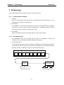


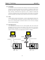
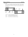

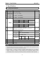
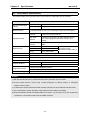
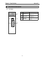
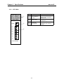
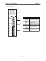
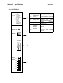
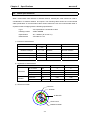


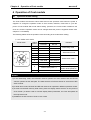

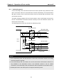
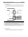


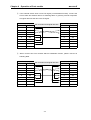
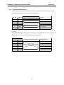

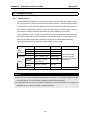
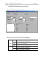
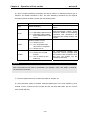
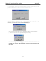
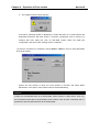
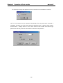


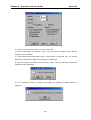
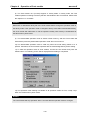
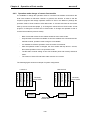


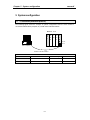
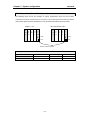
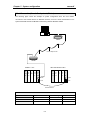

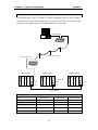

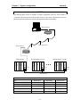
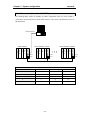
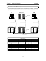
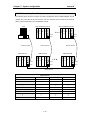


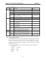
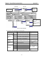

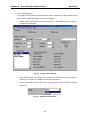
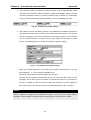
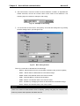

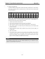

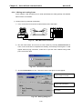
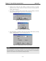
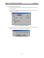

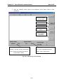
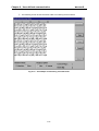

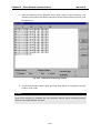
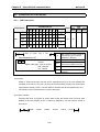
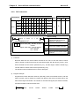


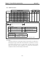
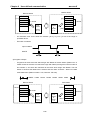
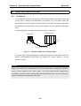
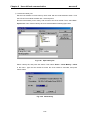
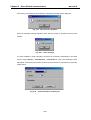


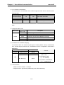


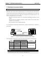


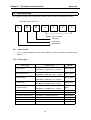

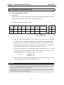

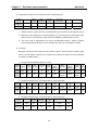
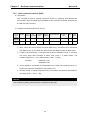
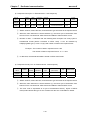
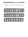
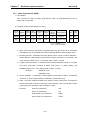
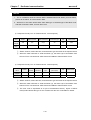


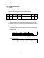
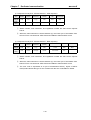
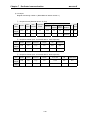
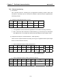
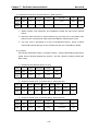

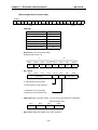


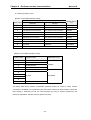
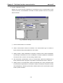


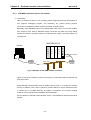
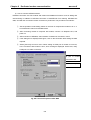
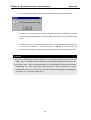
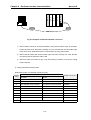

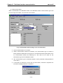
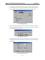

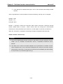

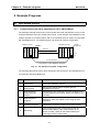


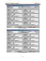

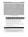
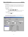

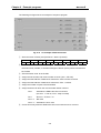

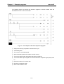
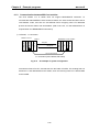
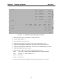
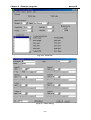
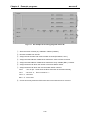
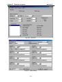
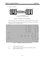
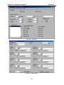
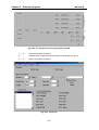
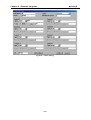
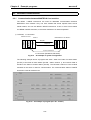

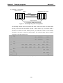


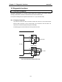
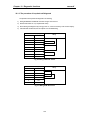

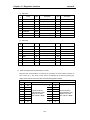


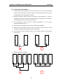
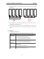
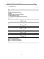

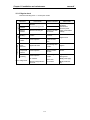
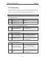
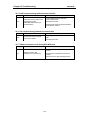
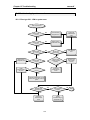
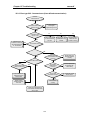
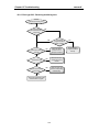

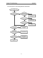
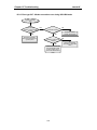

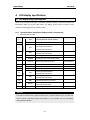
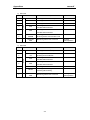
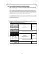
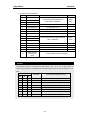
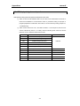

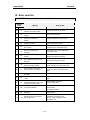

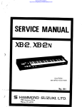

![[11] Chap.9 Installation and Wiring](http://vs1.manualzilla.com/store/data/005904878_1-e83dc78a4328ff11b1e565de6734c05d-150x150.png)