1
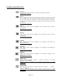
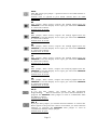
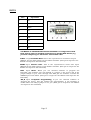
PWR:
Pin #
Signal Name
1
Power Input
2
GND
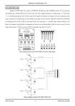
The power input should be +(9-12VDC)/6VAC.
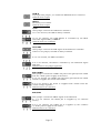
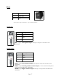
Audio In:
Pin #
Signal Name
1
NC
2
GND
3
MCP
MCP Input Microphone Input. This pin is input to the DSP codec
VS1002D.
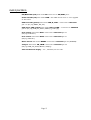
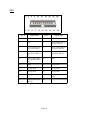
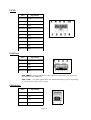
Audio Out:
Pin #
Signal Name
1
LEFT
2
GBUF
3
RIGHT
LEFT OutputLeft channel output. This pin is output for the DSP codec
VS1002D.
GBUF OutputVirtual ground for audio output, 1.23 V nominal. This pin is
output for the DSP codec VS1002D.
RIGHT OutputRight channel output. This pin is output for the DSP codec
VS1002D.
Page 17