1
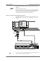
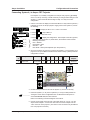
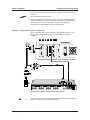
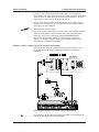
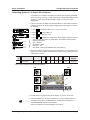
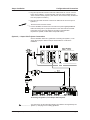
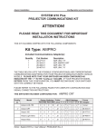
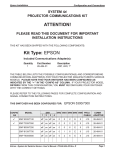
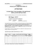
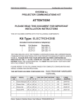
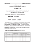
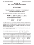
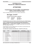
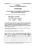
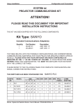
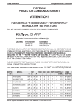
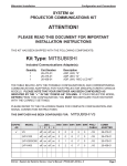
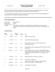
Ampro Installation
Configuration and Connections
SYSTEM 4xi
PROJECTOR COMMUNICATIONS KIT
ATTENTION!
PLEASE READ THIS DOCUMENT FOR IMPORTANT
INSTALLATION INSTRUCTIONS
THIS KIT HAS BEEN SHIPPED WITH THE FOLLOWING COMPONENTS:
Kit Type: AMPRO
Included Communications Adapter(s):
Quantity
1
1
1
1
Part Number
26-477-01
26-304-01
26-468-01
26-467-01
Description
ADP, UNV, “H”
ADP, AMPRO CRT
ADP, UNV, “B”
ADP, UNV, “A”
THE TABLE BELOW LISTS THE POSSIBLE CONFIGURATION(S) AND CORRESPONDING
COMMUNICATIONS ADAPTER(S) FOR YOUR PROJECTOR MANUFACTURER’S VARIOUS
MODELS. PLEASE NOTE THAT YOUR SWITCHER HAS BEEN CONFIGURED AS
INDICATED BY THE “✔” IN THE “CONFIG AS” COLUMN. IF YOUR PROJECTOR MODEL
DIFFERS FROM THIS CONFIGURATION, YOU MUST RECONFIGURE YOUR SWITCHER
WITH THE CORRECT SETTINGS.
PLEASE REFER TO THE FOLLOWING PAGES FOR COMPLETE CONFIGURATION AND
SIGNAL CONNECTION INSTRUCTIONS.
THIS SWITCHER HAS BEEN CONFIGURED FOR:
CONFIG
AS
✔
MODEL
1
SW1
2 3
AMPRO CRT
SW2 SW3 SW4 SW5 SW6 PROJ
4
CABLE
COMM
ADAPTER
Ampro LCD-150 off on off on
0
0
B
2
0
J15
<none>
Ampro 160
off on off on
0
0
F
F
0
J15
26-477-01
Ampro CRT
on off off on
1
0
0
5
0
J15
26-304-01
Amp Light Valve on off off on
1
0
0
5
0
J15
26-468-01
Ampro Alice
1
0
0
5
0
J15
26-467-01
off on off on
Extron • System 4xi Switcher Series • User’s Manual • P/N 68-404-02 Rev. A
Ampro Installation
Configuration and Connections
Connecting System 4xi to Ampro LCD-150
If the System 4xi is already configured for a Ampro LCD-150 projector, go to
step 4. If it is not set up correctly, it will be necessary to change switch settings
on the System 4xi ’s Main Controller Board. Begin at Step 1 to verify the correct
configuration.
1. Use the Front Panel to display the Information Menu to verify that the System 4xi
is already set up for the Ampro LCD-150. Apply power to the System 4xi and do
the following:
a. Press
b. Press
[System 4 model and software
version displayed here]
(See note.)
(See note.)
(See note.)
(See note.)
(Note: Information depends on
System 4 setup.)
}
c. Press
to display the MENU SELECT on the LCD screen.
or
to step to Menu 8.
to select this menu.
d. Press
or
to display the configuration. The example to the left is general,
yours will show the System 4xi model name, the software version and the
following information:
PRJ = AMPRO
PRJ BAUD = 9600
UNIT No. = 000
HST BAUD = 9600 (value depends upon setup Menu 3)
2. Go to the procedure on page 2-3 of the System 4xi User’s Manual to remove the
System 4xi cover. Then go to page 2-4 and refer to the configuration below to
set up the Main Controller board. Continue with Step 3 (below) when the
configuration is correct.
Config
as
Projector
SW1: 1-2-3-4 SW2 SW3
Ampro LCD-150
off-on-off-on
0
0
SW4 SW5 SW6 Prj Cable
B
2
0
Comm
Adapter
J15
SW3
26-475-01
SW5
SW2
J15
SW1
1
2
3
SW4
4
ON
3. Double-check your work and be sure the System 4xi cover is on securely.
4. Install the System 4xi in its place of operation (i.e. rack), but not powered on.
__________ Changes in some switch configurations are not detected until the power is
removed at the AC cord, and then restored.
Refer to the following connection diagram and continue.
5. The Ampro LCD-150 Comm Adapter (26-475-01) has a 9-pin male connector
that accommodates the Comm Extension cable. The other end of the Comm
Adapter plugs into the projector’s RS-232C port.
Extron • System 4xi Switcher Series • User’s Manual • P/N 68-404-02 Rev. A
Page 1
Ampro Installation
Configuration and Connections
6. Plug the 15-pin HD connector of the Projector Communications Extension cable
into the PJ Comm port on the System 4xi.
______ Secure all of the connector screws.
7. Plug the (4 or 5) BNC connectors from one end of the (user-supplied) RGBS/HV
cable onto the System 4xi output and those on the other end onto the matching
BNCs on the Ampro LCD-150 connector panel.
System 4xi Series – Ampro LCD-150 Projector Connections
Use the illustration below as a guide when connecting the System 4xi to an
Ampro LCD-150 projector. Refer to Ampro documentation to continue the
installation.
VIDEO
INPUT
RGB1
OUTPUT
RGB2
RGB1 INPUT
RGB OUTPUT
SYNC
75Ω TTL
S-VIDEO
INPUT
RGB2 INPUT
REMOTE
SYNC
75Ω TTL
Connecting the System 4xi to an Ampro LCD-150 Projector
____________ In a rack mount, do NOT allow the weight of the cables to be supported by the
System 4xi. See page 2-5 for cabling guidelines.
Extron • System 4xi Switcher Series • User’s Manual • P/N 68-404-02 Rev. A
Page 2
Ampro Installation
Configuration and Connections
Connecting System 4xi to Ampro 160
If the System 4xi is already configured for a Ampro 160 projector, go to step 4.
If it is not set up correctly, it will be necessary to change switch settings on the
System 4xi ’s Main Controller Board. Begin at Step 1 to verify the correct
configuration.
1. Use the Front Panel to display the Information Menu to verify that the System 4xi
is already set up for the Ampro 160. Apply power to the System 4xi and do the
following:
a. Press
b. Press
[System 4 model and software
version displayed here]
(See note.)
(See note.)
(See note.)
(See note.)
(Note: Information depends on
System 4 setup.)
}
c. Press
to display the MENU SELECT on the LCD screen.
or
to step to Menu 8.
to select this menu.
d. Press
or
to display the configuration. The example to the left is general,
yours will show the System 4xi model name, the software version and the
following information:
PRJ = AMPRO
PRJ BAUD = 9600
UNIT No. = 000
HST BAUD = 9600 (value depends upon setup Menu 3)
2. Go to the procedure on page 2-3 of the System 4xi User’s Manual to remove the
System 4xi cover. Then go to page 2-4 and refer to the configuration below to
set up the Main Controller board. Continue with Step 3 (below) when the
configuration is correct.
Config
as
Projector
Ampro 160
SW1: 1-2-3-4 SW2 SW3
off-on-off-on
0
0
SW4 SW5 SW6 Prj Cable
F
F
0
Comm
Adapter
J15
SW3
26-477-01
SW5
SW2
J15
SW1
1
2
3
SW4
4
ON
3. Double-check your work and be sure the System 4xi cover is on securely.
4. Install the System 4xi in its place of operation (i.e. rack), but not powered on.
__________ Changes in some switch configurations are not detected until the power is
removed at the AC cord, and then restored.
Refer to the following connection diagram and continue.
5. The Ampro 160 Comm Adapter (26-477-01) has a 9-pin male connector that
accommodates the Comm Extension cable. The other end of the Comm Adapter
plugs into the projector’s RS-232C port.
Extron • System 4xi Switcher Series • User’s Manual • P/N 68-404-02 Rev. A
Page 3
Ampro Installation
Configuration and Connections
6. Plug the 15-pin HD connector of the Projector Communications Extension cable
into the PJ Comm port on the System 4xi.
______ Secure all of the connector screws.
7. Plug the (4 or 5) BNC connectors from one end of the (user-supplied) RGBS/HV
cable onto the System 4xi output and those on the other end onto the matching
BNCs on the Ampro 160 connector panel.
System 4xi Series – Ampro 160 Projector Connections
Use the illustration below as a guide when connecting the System 4xi to an
Ampro 160 projector. Refer to Ampro documentation to continue the installation.
RS - 232C
Side Panel
H
CommAdapter
26-477-01 "H"
9-Pin Female
Rear Panel
RGBHV 5 BNC
15-Pin
Male
INPUT 1
H/HV
R/C
INPUT 2
V
G/Y
AUDIO
B
H/HV
R/C
INPUT 3
V
G/Y
AUDIO
B
H/HV
R/C
INPUT 4
V
G/Y
AUDIO
B
H/HV
R/C
OUTPUT
V
G/Y
AUDIO
PJ COMM
B
RS 232
H/HV
V
R/C
AUDIO
G/Y
B
Connecting the System 4xi to an Ampro 160 Projector
____________ In a rack mount, do NOT allow the weight of the cables to be supported by the
System 4xi. See page 2-5 for cabling guidelines.
Extron • System 4xi Switcher Series • User’s Manual • P/N 68-404-02 Rev. A
Page 4
Ampro Installation
Configuration and Connections
Connecting System 4xi to Ampro Light Valve Projector
If the System 4xi is already configured for an Ampro projector, go to step 4. If it
is not set up correctly, it will be necessary to change switch settings on the
System 4xi ’s Main Controller Board. Begin at Step 1 to verify the correct
configuration.
1. Use the Front Panel to display the Information Menu to verify that the System 4xi
is already set up for the Ampro projector. Apply power to the System 4xi and do
the following:
a. Press
b. Press
[System 4 model and software
version displayed here]
(See note.)
(See note.)
(See note.)
(See note.)
(Note: Information depends on
System 4 setup.)
to display the MENU SELECT on the LCD screen.
or
c. Press
to step to Menu 8.
to select this menu.
}
d. Press
or
to display the configuration. The example to the left is general,
yours will show the System 4xi model name, the software version and the
following information:
PRJ = AMPRO
PRJ BAUD = 9600
UNIT No. = 001
HST BAUD = 9600 (value depends upon setup Menu 3)
2. Go to the procedure on page 2-3 to remove the System 4xi cover and then go to
page 2-4 to set up the Main Controller board. Return to Step 3 (below) when the
configuration is correct.
Config
as
Projector
SW1: 1-2-3-4 SW2 SW3
Ampro Light Valve
on-off-off-on
1
0
SW4 SW5 SW6 Prj Cable
0
5
0
Comm
Adapter
J15
26-468-01
SW3
SW5
SW2
J15
SW1
1
2
3
SW4
4
ON
3. Double-check your work and be sure the System 4xi cover is on securely.
4. Install the System 4xi in its place of operation (i.e. rack), but not powered on.
__________ Changes in some switch configurations are not detected until the power is
removed at the AC cord, and then restored.
Refer to the following connnection diagram and continue.
5. Plug the Comm Adapter’s 9-pin female connector onto the male connector on
the rear panel of the Ampro Light Valve projector. Connect one end of the CC
50’ cable into the Comm Adapter.
Extron • System 4xi Switcher Series • User’s Manual • P/N 68-404-02 Rev. A
Page 5
Ampro Installation
Configuration and Connections
6. Plug the 9-pin male connector of the CC 50' cable into the PJ Comm port of
System 4xi.
____ Secure all of the connector screws.
7. Connect the BNC connectors from one end of the (user-supplied) RGBS/HV
cable onto the System 4xi output and those on the other end onto the BNC
connectors on the rear of the projector according to the application
requirements. (RGsB, S-Video and/or Composite Video).
System 4xi - Ampro Light Valve Projector Connections
Use the illustration below as a guide when connecting the System 4xi to an
Ampro Light Valve projector. Refer to Ampro documentation to continue the
installation.
AM LV COM
"B"
26-468-01
"B"
Connecting the System 4xi to an Ampro Light Valve Projector
____________ In a rack mount, do NOT allow the weight of the cables to be supported by the
System 4xi. See page 2-5 for cabling guidelines.
Extron • System 4xi Switcher Series • User’s Manual • P/N 68-404-02 Rev. A
Page 6
Ampro Installation
Configuration and Connections
Connecting System 4xi to Ampro CRT Projector
If the System 4xi is already configured for an Ampro CRT projector, go to step
4. If it is not set up correctly, it will be necessary to change switch settings on the
System 4xi ’s Main Controller Board. Begin at Step 1 to verify the correct
configuration.
1. Use the Front Panel to display the Information Menu to verify that the System 4xi
is already set up for the Ampro projector. Apply power to the System 4xi and do
the following:
a. Press
b. Press
[System 4 model and software
version displayed here]
(See note.)
(See note.)
(See note.)
(See note.)
(Note: Information depends on
System 4 setup.)
to display the MENU SELECT on the LCD screen.
or
c. Press
to step to Menu 8.
to select this menu.
}
d. Press
or
to display the configuration. The example to the left is general,
yours will show the System 4xi model name, the software version and the
following information:
PRJ = AMPRO
PRJ BAUD = 9600
UNIT No. = 001
HST BAUD = 9600 (value depends upon setup Menu 3)
2. Go to the procedure on page 2-3 to remove the System 4xi cover and then go to
page 2-4 to set up the Main Controller board. Return to Step 3 (below) when the
configuration is correct.
Config
as
✔
Projector
Ampro CRT
SW1: 1-2-3-4 SW2 SW3
on-off-off-on
1
0
SW4 SW5 SW6 Prj Cable
0
5
0
Comm
Adapter
J15
26-304-01
SW3
SW5
SW2
J15
SW1
1
2
3
SW4
4
ON
3. Double-check your work and be sure the System 4xi cover is on securely.
4. Install the System 4xi in its place of operation (i.e. rack), but not powered on.
__________ Changes in some switch configurations are not detected until the power is
removed at the AC cord, and then restored.
Refer to the following connection diagram and continue.
5. Plug the 9-pin female connector end of the cable shown as “ CC 50' ” into the
Ampro Comm adapter. Connect the other end of the Comm adapter into the
“Host” connector of the projector. (The name on the connectors may be different
from one projector to another.)
Extron • System 4xi Switcher Series • User’s Manual • P/N 68-404-02 Rev. A
Page 7
Ampro Installation
Configuration and Connections
6. Plug the 9-pin male connector of the CC 50' cable into the PJ Comm port of
System 4xi.
____ Secure all of the connector screws.
7. Connect the BNC connectors from one end of the (user-supplied) RGBS/HV
cable onto the System 4xi output and those on the other end onto the BNC
connectors on the rear of the projector according to the application
requirements. (RGsB, S-Video and/or Composite Video).
System 4xi - Ampro CRT Projector Connections
Use the illustration below as a guide when connecting the System 4xi to an
Ampro CRT projector. Refer to Ampro documentation to continue the
installation.
15-Pin
Connecting the System 4xi to an Ampro CRT Projector
____________ In a rack mount, do NOT allow the weight of the cables to be supported by the
System 4xi. See page 2-5 for cabling guidelines.
Extron • System 4xi Switcher Series • User’s Manual • P/N 68-404-02 Rev. A
Page 8
Ampro Installation
Configuration and Connections
Connecting System 4xi to Ampro Type II (CRT) Projector
This procedure is the same as the previous one, except for the adapter cabling.
If the System 4xi is already configured for an Ampro projector, go to step 4. If it
is not set up correctly, it will be necessary to change switch settings on the
System 4xi ’s Main Controller Board. Begin at Step 1 to verify the correct
configuration.
1. Use the Front Panel to display the Information Menu to verify that the System 4xi
is already set up for the Ampro projector. Apply power to the System 4xi and do
the following:
to display the MENU SELECT on the LCD screen.
a. Press
b. Press
[System 4 model and software
version displayed here]
or
c. Press
(See note.)
(See note.)
(See note.)
(See note.)
(Note: Information depends on
System 4 setup.)
to step to Menu 8.
to select this menu.
}
d. Press
or
to display the configuration. The example to the left is general,
yours will show the System 4xi model name, the software version and the
following information:
PRJ = AMPRO
PRJ BAUD = 9600
UNIT No. = 001
HST BAUD = 9600 (value depends upon setup Menu 3)
2. Go to the procedure on page 2-3 to remove the System 4xi cover and then go to
page 2-4 to set up the Main Controller board. Return to Step 3 (below) when the
configuration is correct.
Config
as
Projector
Ampro Type II
SW1: 1-2-3-4 SW2 SW3
on-off-off-on
1
0
SW4 SW5 SW6 Prj Cable
0
5
0
Comm
Adapter
J15
26-322-01*
* Type II Comm Adapter must be ordered separately
SW3
SW5
SW2
J15
SW1
1
2
3
SW4
4
ON
3. Double-check your work and be sure the System 4xi cover is on securely.
4. Install the System 4xi in its place of operation (i.e. rack), but not powered on.
__________ Changes in some switch configurations are not detected until the power is
removed at the AC cord, and then restored.
Refer to the following connection diagram and continue.
Extron • System 4xi Switcher Series • User’s Manual • P/N 68-404-02 Rev. A
Page 9
Ampro Installation
Configuration and Connections
5. The Type II Ampro Comm Adapter (AM COM Type II) is a “Y” cable that
accommodates both wired remote and switcher control. Plug the 15-pin HD male
connector of the “Y” cable into the PJ Comm port on the System 4xi. Plug the
middle 15-pin connector into the Ampro remote control.
6. Plug the 15-pin male connector of the cable marked “CC 50' Type II” into the
projector “Host” connector and the 15-pin female connector to the remaining
connector on the Comm Adapter.
____ Secure all of the connector screws.
7. Plug the (4 or 5) BNC connectors from one end of the (user-supplied) RGBS/HV
cable onto the System 4xi output and those on the other end onto the BNC
connectors on the rear of the projector (marked RGsB/RGBS/RGBHV).
Use the following connection diagram as a guide when connecting the
System 4xi to an Ampro projector, using a Type II adapter. Refer to Ampro
documentation to continue the installation.
System 4xi Series – Ampro Type II CRT Projector Connections
15-Pin
15-Pin
Use the illustration below as a guide when connecting the System 4xi to an
Ampro Type II projector. Refer to Ampro documentation to continue the
installation.
Connecting the System 4xi to an Ampro Type II CRT Projector
____________ In a rack mount, do NOT allow the weight of the cables to be supported by the
System 4xi. See page 2-5 for cabling guidelines.
Extron • System 4xi Switcher Series • User’s Manual • P/N 68-404-02 Rev. A
Page 10
Ampro Installation
Configuration and Connections
Connecting System 4xi to Ampro Alice Projector
If the System 4xi is already configured for an Ampro Alice projector, go to step
4. If it is not set up correctly, it will be necessary to change switch settings on the
System 4xi ’s Main Controller Board. Begin at Step 1 to verify the correct
configuration.
1. Use the Front Panel to display the Information Menu to verify that the System 4xi
is already set up for the Ampro projector. Apply power to the System 4xi and do
the following:
a. Press
b. Press
c. Press
[System 4 model and software
version displayed here]
(See note.)
(See note.)
(See note.)
(See note.)
(Note: Information depends on
System 4 setup.)
to display the MENU SELECT on the LCD screen.
or
to step to Menu 8.
to select this menu.
}
d. Press
or
to display the configuration. The example to the left is general,
yours will show the System 4xi model name, the software version and the
following information:
PRJ = AMPRO
PRJ BAUD = 9600
UNIT No. = 001
HST BAUD = 9600 (value depends upon setup Menu 3)
2. Go to the procedure on page 2-3 to remove the System 4xi cover and then go to
page 2-4 to set up the Main Controller board. Return to Step 3 (below) when the
configuration is correct.
Config
as
Projector
Ampro Alice
SW1: 1-2-3-4 SW2 SW3
off-on-off-on
1
0
SW4 SW5 SW6 Prj Cable
0
5
0
J15
Comm
Adapter
26-467-01*
* Type II Comm Adapter must be ordered separately
SW3
SW5
SW2
J15
SW1
1
2
3
SW4
4
ON
3. Double-check your work and be sure the System 4xi cover is on securely.
4. Install the System 4xi in its place of operation (i.e. rack), but not powered on.
__________ Changes in some switch configurations are not detected until the power is
removed at the AC cord, and then restored.
Refer to the following connection diagram and continue.
Extron • System 4xi Switcher Series • User’s Manual • P/N 68-404-02 Rev. A
Page 11
Ampro Installation
Configuration and Connections
5. Plug the 9-pin female connector end of the cable shown as “ CC 50' ” into the
Ampro Comm adapter. Connect the other end of the Comm adapter into the
“Host” connector of the projector. (The name on the connectors may be different
from one projector to another.)
6. Plug the 9-pin male connector of the CC 50' cable into the PJ Comm port of
System 4xi.
____ Secure all of the connector screws.
7. Connect the BNC connectors from one end of the (user-supplied) RGBS/HV
cable onto the System 4xi output and those on the other end onto the BNC
connectors on the rear of the projector according to the application
requirements. (RGsB, S-Video and/or Composite Video).
System 4xi - Ampro Alice Projector Connections
Use the illustration below as a guide when connecting the System 4xi to an
Ampro Alice projector. Refer to Ampro documentation to continue the
installation.
15-Pin
Connecting the System 4xi to an Ampro Alice Projector
____________ In a rack mount, do NOT allow the weight of the cables to be supported by the
System 4xi. See page 2-5 for cabling guidelines.
Extron • System 4xi Switcher Series • User’s Manual • P/N 68-404-02 Rev. A
Page 12