1
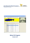
Riverwatcher Software
User Manual
Winari Software
Version: June 2015
VAKI
Akralind 4
IS-201 Kópavogur
Iceland
Tel. +354 - 595 3000
Fax. +354 - 595 3001
e-mail: [email protected]
www.vaki.is / www.riverwatcher.is
1|Page
1.
Contents
2.
THE RIVERWATCHER FISH COUNTER ............................................................ 3
3.
GETTING STARTED ........................................................................................... 4
Installation .................................................................................................................................................................................... 4
1.1.1 First time user or no data available. .............................................................................................................................. 4
1.1.2 You have previous data you want to upgrade with your program. ............................................................................. 10
1.2
4.
Installing newer version ................................................................................................................................................ 10
USING THE PROGRAM .................................................................................... 12
2.1 The Interface ......................................................................................................................................................................... 12
2.2
The Toolbars .................................................................................................................................................................. 12
2.2.1 Counter ....................................................................................................................................................................... 12
2.2.2 File .............................................................................................................................................................................. 13
2.2.3 Images ......................................................................................................................................................................... 14
2.2.4 About .......................................................................................................................................................................... 14
2.3
The silhouette image field ............................................................................................................................................. 14
2.3.1 The Window ............................................................................................................................................................... 14
2.3.2 Add/Remove files ....................................................................................................................................................... 14
5.
CONNECT ......................................................................................................... 15
2.4
Settings ........................................................................................................................................................................... 17
2.4.1 Size Groups ................................................................................................................................................................. 18
2.2.1 Communication........................................................................................................................................................... 18
2.2.1 Categories ................................................................................................................................................................... 18
2.2.1 Camera images............................................................................................................................................................ 19
2.2.1 Charts .......................................................................................................................................................................... 19
2.4.5.1 Time chart ................................................................................................................................................................ 19
2.4.5.2
Length chart ........................................................................................................................................................... 19
2.4.5.3
Print Margins ......................................................................................................................................................... 19
2.4.5 Report settings ............................................................................................................................................................ 20
2.4.5 Filter............................................................................................................................................................................ 20
2.5.1 Exit .............................................................................................................................................................................. 20
2.6
Silhouette........................................................................................................................................................................ 20
2.7
Table field ...................................................................................................................................................................... 20
3.7.1.Size/Time ........................................................................................................................................................................ 21
3.7.2. The temperature ............................................................................................................................................................ 22
3.7.3. ”File records”................................................................................................................................................................. 22
3.7.4. The”Visibility” .............................................................................................................................................................. 22
2.8
The Chart field .............................................................................................................................................................. 23
3.8.1 Stacked Chart.................................................................................................................................................................. 23
3.8.2. Time Chart ..................................................................................................................................................................... 24
3.8.3. Migration Chart ............................................................................................................................................................. 24
3.8.4. Length Chart .................................................................................................................................................................. 25
3.8.5. Year Comparison Chart ................................................................................................................................................. 25
3
UNDERWATER CAMERA CONNECTION (OPTIONAL) ................................. 26
4
ERROR SOURCES ........................................................................................... 27
4.1
Error in line ................................................................................................................................................................... 27
2|Page
2. The Riverwatcher Fish Counter
The Riverwatcher is a Fish Counter for use in fish ladders, barrier dams or other places where fish swim
through a restricted passage. Various versions are available, and the counter can be adapted to local
conditions in each individual instance. The Riverwatcher consists of a Control Unit with software, a
Scanner Unit with cables, solar-panel, batteries and a computer program for processing the data.
The Scanner Unit can be thought of as a gate that is placed in the fish ladder. It controls the emissions of
infrared light beams from the light-emitting one side of the Scanner Unit and the signals from the
receivers on the other side of the unit.
When a fish swims through the Scanner Unit it interrupts the beams, the silhouette of the fish being
used to count it and calculate its size. One cable runs between the Scanner plates, and there is one cable
connecting the Scanner to the Control Unit. Data sent from the Scanner Unit to the Control Unit, which
can then be transferred to a computer program, consist of: the height of the fish, the date and time it
swam through the Scanner Unit, the temperature of the river, the results of a vision test which is carried
out at regular intervals to check on the condition of the Scanner Unit’s light-emitting diodes and a
silhouette image of every fish so the counting’s can be verified afterwards.
3|Page
3. Getting started
The program can be reach at [email protected] or on Riverwatcher webpage under Support.
http://www.riverwatcher.is/Support/
Please select one of the options below before installing the program that fit your situation and after that
follow the correct installation practice.
1. First time user or no data available.
2. You have previous data you want to upgrade with your program.
Installation
1.1.1 First time user or no data available.
Download program from webpage or via e-mail. When the program is run this window opens. This is
done in four steps.
1. Download program from
webpage or via e-mail.
VAKIWinari file is saved in
Program file and under VAKI
and Winari folder.
2. Run winari_setup. The type:
Applicatio. Click on
winari_setup logo and run it.
3. Then the following window should
open. Make sure the Winariis
installed to C:\Program
Files\vaki\Winari. Then press next.
4|Page
4. The Program Folder should be
Winari. Choose to install this
application for either all user or just
current user. Then press next.
5. The installing window will show up.
Click next when the installation is
finished.
6. Next select Run Winari now and
press finish. Then the VAKIWinari is
installed.
7. To active the video function of
Winari it is necessary to install vlc. If
this program is not installed Winari
will show this error sign.
8. To install vlc open the vaki\winari
file og to Program
files\Vaki\winari select Vlc to
install.
5|Page
9. Then Installer Language window will
show up. Select language.
10. Click on next to continue on the
welcome to Video LAN VLC media
player setup window.
11. Agree the License Agreement by
clicking next to continue.
12. Choose the Components select type of
install is “Recommended” and then press
next.
13. Choose Install Location and let the
destination folder be C:\Program
File\VideoLAN\VLC and press Install.
6|Page
14. The installing window will show up. Just
wait for the program to be installed. Press
next when the Installation is finished
15. Select Run Video LAN VLC media player
and press Finished.
7|Page
1. Comport
To connect the computer to the frame without internet connection, usb serial convertor needs to be
installed on the computer. Insert the usb converter CD that was delivered with the frame. It is not
from any specific producer so the installation could be slightly different. Run the cd from the
Removable Storage
16. Check if there comperter er already
insert.
Go to control Panel\Device
Manager\ dobble click in Device
Manager.
17. Select ports and see if there are
Comm port there. If the are not you
have to install it.
18. If the program is not installed insert
the CD to the computer and run it.
8|Page
19.
Dobble click on Run Autorun and press
yes on the Run button.
20. For this Converter click on Install Driver
21. Press next on the welcome window.
22. Select install to install the program.
23. To finish the installation press the finish
button.
9|Page
24. To make sure the USB to serial program
is installed go to the Device manager
again and check it.
1.1.2 You have previous data you want to upgrade with your program.
1.2 Installing newer version
Import existing data into new Winari database
1. If there are upgrading Winari and have
already winari data you need to import
exsisting data into the new data base that
is done with the program DBimportexport.
2. Choose Import tables from DBE/ODBC
and press Next
10 | P a g e
3. Choose Import using DBE Alias / ODBC
DSN and press Next
4. Choose winari as import aliases and
select all tables to import and click Next
Write winari.abs in the database file field
and click next. The program will now
import all Winari data into database.
Click Finish. Now the data will be
accessible in Winari.
11 | P a g e
4. Using the program
2.1 The Interface
The interface is easy to use and provides excellent overview over the collected data. Moreover it
includes variety of tables and charts for viewing and analysing figures and numbers. The program
interface is divided into four main fields;
1. Toolbar
2. The Silhouette Image Field
The silhouette image field gives
information about the size and form.
3. The Digital Camera Field
The digital camera field provides you
possibility to distinguish between
species and group the fish in
predefined groups.
with the
different
4. The Table / Chart Field
Shows detailed information on each fish. Five different charts shows the whole season, time of
day, missing one, size graph and compare more than one season together.
2.2
The Toolbars
The main toolbar shows: counter, file, images, and about buttons. These buttons will be described in
this chapter 3.1.The button toolbar is part of the silhouette image field and is described in chapter 4.
Has a shortcut on the other toolbar except the empty window and the filter button.
2.2.1 Counter
New counter
Here can you add the counters that are used in the database of the program. They are given name,
description, phone number and counter number.
12 | P a g e
Modify counter
Here can you modify the counters that are used in the database of the program. They are given name,
description, phone number and counter number.
Delete counter
Here can you delete the counters that are used in the database of the program.
Export counter
Here can you export counter to another computer/user?
Import counter
Here can you import counter from another computer/user?
Create report
Here can you report that statistics of fish swimming up and down the river. Statistical graphs are also
drawn up. The fish amount versus time.
Settings
This is used to change the name or size-range of the categories, choose other colours for the charts and
set the communication port (COM port) to be used for data transfer to the computer. In addition the
user can choose length/depth constant for each fish group. This constant is used to calculate the length
of the fish by using measured depth. Under settings it is also possible to change some settings on the
charts.
Exit
For exit and close down the program. This does not affect the work done in the database.
2.2.2 File
Add remove files
By adding files in the database the user is able to analyse silhouette images of each fish, and sort the fish
in different groups by the look. It is possible to add several files to the same database, and make several
databases for different counters. In this database it is possible to look at each single fish, in addition to
other registrations such as depth, speed, position in the counter, swimming direction etc.
Connect
This function is used for download data from the control unit. When data is downloaded four types of
file exist. Each with a different function and they are stored in the same folder. If the control unit is
fitted with a connection to a (mobile) telephone and modem, then it is possible to dial up a connection
to the counter at any time for monitoring and data collection.
Go to fish record
Select date to go to, to see counted fish in on that date.
Copy chart to clipboard
Here you can copy the active chart to the clipboard and then paste it if working with other documents.
Copy Silhouette to clipboard
This module is used to copy silhouette to clipboard.
13 | P a g e
Print Chart
This module is for printing the active chart.
Export to Excel
This module exports data to excel.
2.2.3 Images
Silhouette
Here you can able / disable the silhouette image field from the main program interface.
Digital Camera
Here you can able / disable the digital camera field from the main program interface.
2.2.4 About
This gives information about the current edition of the program in use, and about VAKI.The Winari
program is designed for Windows 95/98/W2K/XP and consists of following main modules.
2.3
The silhouette image field
To toolbar over the silhouette image field are shortcuts from the main toolbar except the filter button
and the silhouette button. This chapter will go through the lower menu bar and the silhouette image
field.
2.3.1 The Window
Choose active river watcher.
2.3.2 Add/Remove files
It is possible to build a database for each fish counter created, and sort the registrations in predefined
groups using the silhouette images of each fish.
When new data is downloaded into the program,
”Add/Remove Files” and the following is displayed.
data from the Control Unit is downloaded every
new sets of files are made every time (arv, img, tdt,
they together make the database. In this window
remove or add new files (measurements) and
press
If the
week,
vsb) and
you can
14 | P a g e
comments. The “File nr:” is the number of the file that is being imported to the database.
5. Connect
2.3.3.1. The files
The following four types of file are stored in the folder when data is transferred from the control unit.
.arvfiles, which contain data on the size of the fish, the time of registration and the direction the fish,
were swimming and the position in the scanner frame. These are the main files for each record.
.imgfiles, which contains a silhouette image of each fish, this makes it possible to examine and sort all
the fish recorded, and count them to check the numbers recorded automatically by the counter.
.vsbfiles, which contain data from the “visibility test”, this can be used to check whether all the LEDs
(light-emitting diodes) were functioning properly during the period when registrations were made. The
storing capacity in the
vsb file is 100 days.
.tdtfiles, which contains temperature records for the period, the temperature is recorded automatically
every three hours, and the file can store 2.000registrations. The storing capacity in the tdt file is
therefore more than eight months.
2.3.3.2. Direct connection
To retrieve data from the control unit, connect it to the computer using the transfer cable and the
appropriate COM port. Switch on the control unit and click the “Connect” option in the program. The
following will appear on the screen.
15 | P a g e
The date and time of the day on the control unit (DU Clock) will appear automatically under “Counter
Clock”. It is important to check if the DU clock and the date are right, if not it has to be changed.
“Counting Results” are displayed
automatically, and shows the status on the
unit’s display. It does not have to be the
numbers as on the file that is transferred,
possible to reset the control unit from the
computer. That might be preferred if you
show on the DU the total migration for the
period, but the memory is erased after each
downloading. Counter last reset time shows the date and time of last reset.
control
same
since it is
want to
whole
By pressing “ResetCounter” all data from the control unit is erased. Do not erase data before all files are
securely downloaded and saved. By pressing the “Battery/Visibility” button you can check the power on
the battery, and also run a test that tells you if all the diodes are functioning right.
The green dots in the lower right corner indicate activity on the serial port. The following test is shown
for each of the two diode-rows. In the example to the left everything is OK and nothing is blocking the
diodes, but in the example to the right something is blocking the highest part of both diode-rows.
“View Data” shows in a graphical way the file that is being transferred from the control unit (see charts
under chapter 3.5.). Under “Settings” you can choose which file types you transfer from the control unit,
while pressing “Upload” starts the transmission. All files are given a name based on the name of the
river and the date when the data is transferred; these may be altered as in other Windows programs. If
the names are changed, then it is important that the four files from each downloading have the same
name.
2.3.3.3. Modem connection
16 | P a g e
If the control unit is fitted with a telephone
connection
and a modem, then it is possible to dial up a
connection
at any time to download data from the control unit
at any
time or for regular checking. Insert the counters
telephone
number and press “Dial”. When connection is made
between
the control unit and the computer the picture from
chapter
3.3.2 is displayed. All the functions are the same as with direct connection. When downloading big files
via mobile modem, some problems may occur if the telephone connection is bad. Then it is better to
download more frequently and erase the memory after each download.
2.4
Settings
This is used to change the name or size-range of the categories, choose other colours for the charts and
set the communication port (COM port) to be used for data transfer to the computer. In addition the
user can choose length/depth constant for each fish group. This constant is used to calculate the length
of the fish by using measured depth. Under settings it is also possible to change some settings on the
charts.
17 | P a g e
2.4.1 Size Groups
Use this option to change the names or size
boundaries of the categories, and to
determine which of them are to be
displayed on the charts. You can also choose
different colours to represent each category.
2.2.1 Communication
In this window you can choose
communication method, either through
the serial port or a modem. You can also
choose which COM port on the computer
to use when downloading data and which
port to connect the modem to if the
counter has a built- in telephone.
2.2.1
Categories
Here you can change the length/height ratio,
which is used to calculate the length of the
fish on the basis of their measured height. It
is possible to use different constants for each
size groups of the sorted fish groups. This
may be desirable if there are different
relations between depth and length between
fish groups, and between size groups within
fish groups. It is also possible to set a relative constant for calculations of the length according to the
swimming direction. If fish is calculated smaller on the way down then by changing this constant to
e.g. 1.3 the program will calculate the size of all down fish 30% bigger. This can be appropriate if the
fish has to jump into the scanner frame and therefore the shadow is deeper than the shadow of the
same fish swimming down.
18 | P a g e
2.2.1 Camera images
In Camera images you can choose how many
images are shown in the digital camera field of
the program.
2.2.1 Charts
2.4.5.1 Time chart
Select the settings for the temperature
shown in the charts, Celsius or Fahrenheit.
Also it is possible to select daily average or
measurements with three hour intervals
shown. Activate the operating status to see
the results from the VSB file on the chart.
And under “Length Chart” It is possible to
set their solution in the length chart.
2.4.5.2
Length chart
To choose charts length resolution, change
the value in the length Chart resolution (cm)
window.
2.4.5.3
Print Margins
To change the charts placement on the
reports choose the distance value on top,
left, Right, bottom.
19 | P a g e
2.4.5 Report settings
To choose what information´s are shown on
the Reports go to Report settings. Available
information’s for the reports are: Counting
tables, stacked chart, Time Chart, Migrating
chart, Length Chart and Year comparison
Chart.
2.4.5 Filter
In the program it is possible to work with the
whole database or selected part of it by
selecting the group from the “Categories”.
By “Time period” you can also choose a
certain time period to look at. Select also the
direction and size groups to look at in the
charts.
2.5
Create Report
PRinT
Shortcut to print out reports.
2.5.1 Exit
2.6
Silhouette
By pressing the silhouette button the silhouette field/screen shows, no silhouette, silhouette one
silhouette two or both silhouettes at the same time.
2.7
Table field
The “Table field” beneath the silhouette image shows the date and time for each passing fish, the depth
and calculated length (Depth x “Length/depth” ratio under ”Settings”) in addition to categories,
swimming direction, speed, the position in the scanner and the number of the file in the database.
Under “Categories” to the left of the table, there is a possibility to sort the fish in different groups
(species), using the silhouette image and other information from the data file. Under certain
circumstances the counter can register some disturbances in the water surface or objects that are not
20 | P a g e
fish. Then it is possible to go through the silhouette images and manually sort these registrations, either
as “Not Fish” or delete them from the database.
The table beneath the silhouette image has four fields; Size/Time, Temperature, File records and
Visibility.
3.7.1. Size/Time
The first field shows the date and time for each registration. ”Depth” shows the scanned height of the
fish in mm, ”Length” shows calculated length in cm (Depth * L/D ratio for actual size group), “Category”
shows in what group the fish was sorted, ”Direction” shows the swimming direction, “Speed” is shown
in m/sec, ”Frame pos.” shows the position of the fish in the scanner frame, e.g. the number of the
uppermost diode used to draw up the silhouette image of the fish. The diodes are 96 in each row, no. 1
is at the top, and no. 96 is at the bottom. ”File nr” shows which file in the database you are working
with. It is possible to sort the database by pressing the top of any column, e.g. by size or direction. It is
also possible to select many fish at the same time (mark them blue) if the database is being sorted. Just
hold down the Ctrl button while selecting lines with a mouse-click.
21 | P a g e
3.7.2. The temperature
shows the date and time for each
temperature registration, ”Temp” shows
electrical value from the scanner used for
calculating the temperature in Celsius or
Fahrenheit shown in “Calc Temp”, and
shows which file in the database you are
with.
field
the
”File nr”
working
3.7.3. ”File records”contains the counting result from each file that make the database, and information on
measuring period, comments and where to find the file.
3.7.4. The”Visibility” field
the light emitting diodes have
functioning right during the
shows if
been
period.
Each line represents one day,
and
Scanner 1 and Scanner 2 have
one
column each. If the value is 0
the
diodes are functioning right, but
other
numbers show which diodes
have
been blocked for more than
30minutes in one - hour period.
”Battery
faults” can either show 0 or 1,
where 0
means that the Voltage has
been
higher than 11.2 Volt, while 1 means that the Voltage has fallen under 11,2 V. This test says nothing about
how long the Voltage has been under the limits; only it has been under for some period that particular day.
”File nr” is as before to show which file in the database you are working with.
22 | P a g e
2.8
The Chart field
By pressing „Charts”, the chart- module is opened, but only for the sort-categories (Generic, Not Fish, etc.)
or/and the period that is active in the database (set under „Filter”). For more details see chapter 3.7.
3.8.1 Stacked Chart
This chart shows the migration patterns of
the fish, either for the full period or over a
selected part of it. On the Y-axis the number
of fish in each size group is shown per day,
and the date is on the X-axis. Press the
“Filter” button to examine all categories
together or one at a time, and you can set
the boundaries for the category sizes (see
chapter 3.6 Settings).Use the Year, Month,
Day and Hour buttons to examine particular periods in greater detail.
The “Operating Status” (green bar on the X-axis) shows how the system has been performing over the
period. If the light diodes have been blinded for more than 20minutes of the last 60 minutes, then the green
bar turns to red for that day. It also happens if the power of the deep cycle battery has gone under 11.2
Volts.
23 | P a g e
3.8.2. Time Chart
This chart shows the migration pattern of the fish over the period related with the length of the fish. The
length of the fish is shown on the Y-axis and time on the X-axis. Positive lengths denote ascending fish and
negative lengths descending fish.
Each column represents one fish; click on a column for the image of each fish and information about the
length, the registration time, size category, depth in scanner and swimming direction.
The fish may be divided into three size categories as specified by the user (under “Settings”). Specific periods
may be selected by clicking the buttons for Year, Month, Day and Hour.
To enlarge individual parts of the display, hold the left mouse button down and drag the mouse pointer
downwards and to the right. To restore the full display, hold the left mouse button down and drag the
mouse pointer upwards and to the left.
To examine earlier or later periods, hold the right mouse button down and drag the mouse pointer to the
left or right.
The size categories can be changed easily by altering the specified length boundaries. Also, you can specify
the categories to be examined by clicking the “Visible size groups” field in “Settings”.
Under “Direction” you can choose whether you examine fish that climbed or descended the ladder, or both
together, which is the most common setting.
3.8.3. Migration Chart
This shows the time of the day when the fish were recorded. As with the previous charts, you can examine a
particular period or size category in greater detail and choose between fish passing up or down the ladder or
examine both groups together.
24 | P a g e
3.8.4. Length Chart
This shows the breakdown of the fish by size category. In addition to examining one or more size categories
in greater detail, and using the Year, Month, Day and Hour buttons to select periods, you can also alter the
units on the X axis and set them from 1 to 10 cm according to the category you wish to examine (under
Settings).
3.8.5. Year Comparison Chart
This chart shows the comparison of the migration pattern between years, just add files to the database for
the wanted periods.
25 | P a g e
3 Underwater camera connection (optional)
An option to the Riverwatcher is to connect an underwater camera to the system. Then the scanner is used
as a trigger for the camera that takes up to five pictures of the fish. Then the photos are linked to the
silhouette image drawn by the infra-red scanner, so it becomes possible to identify species, sex and other
information of value to the user. This is only possible with a special PC version where a computer with a
special program replaces the yellow control unit. The advantage of this method is that the user, who
examines the data, can quickly go through the photos and analyse them on the computer. Information is
automatically stored in a database file among other data on time of passage, size, temperature and a
silhouette image of the fish from the infrared scanner. Graphs of the migration pattern can be viewed
immediately. For instance: as total number of fish by species, or gender. The size distribution of each fish
species can be viewed and water temperature changes over the season. Having all the information stored in
one database with digital images, greatly reduces the work required to analyse date on fish abundance and
gives more reliable information behaviour pattern of fish in a complex river ecosystems.
The setup of the camera is critical, and there are several factors that can affect the quality and resolution of
the pictures.
1. The placement of the camera
To obtain the best pictures the distance from each fish to the camera must be the same all the time. But the
placement of the camera and the camera angle can be different from fish way to fish way because of
different swimming speed and behaviour of the fish. The before it can be necessary to make some changes
after the first installation and after viewing the pictures.
2. Intervals between pictures and number of pictures
It is possible to set the interval between the pictures and also the number of pictures taken. If the fish swims
with high speed through the scanner frame and by the camera the intervals must be short, but if the fish
even stops in front of the camera then the intervals should be longer. This is something that has to be set
specially for each installation.
3. Light conditions
The camera that is used to take pictures uses infra-red light when the light condition gets poorer. To get
optimal resolution it might give better results to install an extra infra-red light or a regular light with the
camera, especially if the fish is migrating during the night and late in summer/autumn. This is different
between installations.
26 | P a g e
4 Error sources
There are different errors that can occur while using the program.
4.1 Error in line
Sometimes it can happen that an error occurs in some of the lines in the ARV file. This is usually caused by
bad connection over modem. Below is an example of ARV file with two error lines (file A). This error is easy
to fix, all the columns have to be linear so in File B both the lines have been fixed. If there are some data
missing from a line, then the date put in the new line must be in accordance with the date and time in the
lines before and after. The meaning of the columns in the file are A: Fish height mm, B:Scanned length cm, C:
Position in frame, D:Month, E:Day, F:Hour, G:Minute, H:+/- up or down, I:Code
[river]
North ladder
[date]
21/08/2003
[time]
12:39:00
[Startdatetime]
66977.6805556
[Endadatetime]
37854.5270833
[Count values]
Name of counter
Date of download
Time of Download
Coded reset time & date
Coded download time & date
Sal.up :1730
Tr. up :51
Sal.dwn :6
Tr. down :8
[comments]
Fish numbers counted in this file
[images file]
North ladder_20030821.img
[visability file]
North ladder_20030821.vsb
[temperature file]
North ladder_20030821.tdt
[data]
0
Names of the related image, temperature
and counter status files
3
7
30
16
20
Date & time of last counter reset
A
102
110
90
127
95
96
102
B
53
43
51
57
52
71
52
C
44
47
16
59
72
69
47
D
6
6
6
6
6
6
6
E
29
29
29
F
7
8
9
G
55
0
47
H
+
+
+
I
16
16
16
29
29
29
10
10
10
10
14
25
+
+
16
0
16
File B
102
110
90
127
95
96
102
53
43
51
57
52
71
52
44
47
16
59
72
69
47
6
6
6
6
6
6
6
29
29
29
29
29
29
29
7
8
9
10
10
10
10
55
0
47
2
10
14
25
+
+
+
+
+
+
16
16
16
16
16
0
16
File A
NB! The ARV files are the raw-data from the counter. If they are to be changed or altered, then make a copy of
the original one, and make changes to the copy.
27 | P a g e