1
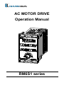
AC MOTOR DRIVE
Operation Manual
RM6S1 series
Quality․Satisfaction․Improvement․Innovation
http://www.rhymebus.com.tw
2014.07.04 Revised
PREFACE
Thank you for using RHYMEBUS RM6S1 series drive. The simple manual version
shall be placed on the top of the machine. For ensure customer operations and
safety purposes, this version offer completely information and instruction of the
product, please do read and follow specific instructions before using the product.
SAFETY PRECAUTION
Please read this manual thoroughly and pay attention to the safety precautions
marked with “ DANGER ” or “ CAUTION ” before the installation, wiring,
maintenance, or troubleshooting.
Only the qualified personnel may proceed with the installation, wiring, testing,
troubleshooting, or other tasks.
※Qualified Personnel: Must be familiar with the fundamentals, structures,
characteristics, operating procedures, and installation, and this personnel must
read the manual in details and follow the steps of security measures to prevent
possible dangers.
DANGER
CAUTION
User may cause the casualty or serious damages if user
does not abide by the instructions of the manual to execute
the tasks.
User may cause injuries to the people or damage the
equipment if user does not abide by the instructions of the
manual to execute the tasks.
※Although the “
” mark may indicate minor damages, serious damages or
injuries may be possibly incurred if the caution is not under user’s attention.
Installation
CAUTION
a. The installation shall take place only on top of the metal surface or any material
with the fire resistant. Any place or location of high temperature, moist, oil and
gas, cotton fiber, metal powder and erosive gas shall be avoided.
b. The option of installing AC reactor(ACL) shall be very cautious.
c. Please note the surrounding temperature shall not exceed 50°C when the
installation needs to be placed inside the control panel.
d. For the environment of storage and installation, please follow the instructions of
the environmental conditions illustrated in the sections of the common
specification of RM6S1.
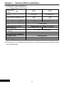
Atmosphere
Surrounding temperature
Storage temperature
Relative humidity
Vibration
Altitude
Non-corrosive or non-conductive, or non-explosive gas or
liquid, and non-dusty
-10°C~+45°C (14°F~122°F) (Non- condensing and
non-freezing)
-20℃~+60℃(-4°F~140°F)
90% RH or less (No-condensing atmosphere)
Less than 5.9m/sec² (0.6G)
Less than 1000m (3280 ft.)
i
Wiring
DANGER
a. Do Not conduct any wiring during the system power ON to avoid the electric shock.
b. L1, L2, are power inputs (electric source terminals) and U,V,W are drive’s outputs
to a motor. Once the wiring is complete, the cover of the drive must be put back
and must seal the drive to avoid other’s accidental contact.
c. The drives have three specifications base on the input power source 200V, Do
Not input the voltage exceed the specifications.
d. The grounding terminal(
) must be exactly grounded. The grounding method
must compliance with the NEC standard or local electrical code.
e. Please refer to the national or local electric code for the appropriate spec of the
cords and wires.
f. Please install an appropriate Molded Case Circuit Breaker (MCCB) or Fuse at
each path of power lines to a drive.
g. Please install the thermal relay between the individual motor and the drive when
using one drive to propel several motors.
h. Do Not connect power factor leading capacitor, surge absorber, or
non-three-phase motor to the drive’s U, V, or W side.
i. Do Not touch the drive or performing any unwiring actions in the 5 minutes before
drive indicator light turns off after the power off.
j. When the motor do the voltage-proof, insulation testing, unwiring the U,V,W
terminal of drive at first.
CAUTION
a. The RM6S1 series outputs are designed to drive a three-phase induction motor.
Do Not use for single-phase motor or using for other purposes.
b. The main circuit and control circuit must be wired separately; control circuit must
use a shielded or twisted-pair shielded wires to avoid possible interferences.
ii
Operation
DANGER
a. Do Not open or remove the cover while power is on or during the drive operation.
Do close up the cover before powering on the drive. Do Not remove the cover
except for wiring or periodic inspection when power off.
b. At the function F3.30= 1 or 3, the drive will automatically restart when the power
is restored. Stay away from the motor and machine.
c. At the function F1.05=0 and F1.00=0 or 1 or 10, the
key on the operation
panel is ineffective. Please use an emergency stop switch separately for safe
operations.
d. The drive can produce high frequency outputs. Before adjusting the frequency,
please check the specs of motor carefully to prevent the motor from unexpected
damages.
e. If any of the protective functions have been activated, and the start command is
set to terminal control(F1.00=0 or 1 or 10), first remove the case and check the
all run commands set to OFF. Then press the
key to release the alarm.
STOP
RESET
STOP
RESET
CAUTION
a. Do Not touch the heat sink due to the high heat.
iii
TAB
Feature
1. The drive has temperature management and setting
pre-alarm level to forecast over temperature.
2. Communication function RS-485 Modbus RTU.
Special function key (SPEC): Cable set (in parameter) to
3. realize FWD/REV running, jog speed, and other
multi-function operation.
4. Built-in knob (Pot) for speed adjustment.
5. The switching frequency can be adjusted between
800Hz~ 16 kHz.
6. Provide 8 sets of monitor displays. (Frequency, speed,
voltage, current and 13 kind of options available)
7. Counter function.
8. To support external PTC for motor overheat protection.
9. User can connect KP-601A keypad (option) for remote
control,parameters duplication and saving.
10. Detachable Buckles design for installation.
11. Six sets of fault record.
(fault record, current, voltage,frequency)
12. Simple parameter group and complete parameter group.
13. Parameter lock and parameter password functions.
.
iv
TABLE OF CONTENTS
CHAPTER 1 CAUTIONS BEFORE INSTALLATION --------------------------- 1
1-1 PRODUCT VERIFICATION -----------------------------------------------------------------1
1-1-1 Confirmation of Appearance --------------------------------------------------------1
1-1-2 The description of nomenclature --------------------------------------------------1
1-1-3 Confirmation of Accessories --------------------------------------------------------1
1-2 STANDARD SPECIFICATIONS -----------------------------------------------------------2
1-2-1 Single-Phase 100V Series ----------------------------------------------------------2
1-3 THE FEATURES OF CONTROL AND OPERATION --------------------------------1
CHAPTER 2 INSTALLATION AND CONFIRMATION --------------------------- 2
2-1 BASIC EQUIPMENT --------------------------------------------------------------------------2
2-2 ENVIRONMENTAL CONDITIONS --------------------------------------------------------2
2-3 BASCI WIRING --------------------------------------------------------------------------------3
2-3-1 Descriptions of Terminal and Wiring Diagram----------------------------------3
2-3-2 Description of Terminals -------------------------------------------------------------3
2-3-3 Control Terminals ----------------------------------------------------------------------3
2-3-4 Modbus Port (RS-485)/ Keypad-601A -------------------------------------------4
2-4 WIRING CAUTIONS AND SPECIFICATIONS -----------------------------------------5
CHAPTER 3 THE SETTING OF OPERATION PANEL & REMOTE
CONTROLLER --------------------------------------------------------------------- 6
3-1 FUNCTION OF OPERATION PANEL ----------------------------------------------------6
3-1-1 Description of indicator ---------------------------------------------------------------6
3-1-2 Function of Key-------------------------------------------------------------------------7
3-2 FUCTIONS OF REMOTE CONTROLLER (KP-601A KEYPAD) -----------------8
3-3 THE OPERATION OF OPERATION PANEL AND MONITOR MODE ----------9
3-3-1 The Operation of Operation Panel ------------------------------------------------9
3-3-2 Monitor Mode ------------------------------------------------------------------------- 10
3-3-3 The Status of Multi-function Terminals ----------------------------------------- 11
3-3-4 The Function Setting Mode ------------------------------------------------------- 11
3-3-5 Parameter Setting Mode ----------------------------------------------------------- 12
3-3-6 The Operation in the Monitor Mode--------------------------------------------- 13
3-3-7 To Start/Stop the Drive ------------------------------------------------------------- 13
3-3-8 Save and Restore the Setting Value. ------------------------------------------- 14
CHAPTER 4 PARAMETER LIST ----------------------------------------------- 15
F0 SYSTEM PARAMETERS------------------------------------------------------------------- 16
F2 FREQUENCY PARAMETERS ------------------------------------------------------------ 20
F3 CONTROL PARAMETERS ---------------------------------------------------------------- 23
F4 PROTECTION PARAMETERS ----------------------------------------------------------- 26
v
F5 MULTI-FUNCTION PARAMETERS ----------------------------------------------------- 28
F6 SPECIAL PARAMETERS ------------------------------------------------------------------ 32
CHAPTER 5 PARAMETER SETTING DESCRIPTION ------------------------ 33
F0 SYSTEM PARAMETERS------------------------------------------------------------------- 33
F1 OPERATION PARAMETERS ------------------------------------------------------------- 35
F2 FREQUENCY PARAMETERS ------------------------------------------------------------ 43
F3 CONTROL PARAMETERS ---------------------------------------------------------------- 50
F4 PROTECTION PARAMETERS ----------------------------------------------------------- 56
F6 SPECIAL PARAMETERS ------------------------------------------------------------------ 73
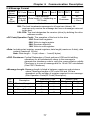
CHAPTER 6 COMMUNICATION DESCRIPTION ------------------------------- 75
6-1 KP-601A / MODBUS PORT (RJ-45) --------------------------------------------------- 75
6-2 THE SETTING OF COMMUNICATION PARAMETER ---------------------------- 76
6-3 COMMUNICATION PROTOCOL -------------------------------------------------------- 76
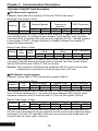
6-4 MESSAGE FORMAT ----------------------------------------------------------------------- 77
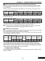
6-5 CRC CHECKSUM ALGORITHM -------------------------------------------------------- 80
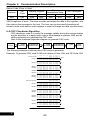
6-6 PROCESSING TIME OF COMMUNICATION TRANSMISSION---------------- 81
6-7 COMMUNICATION TROUBLESHOOTING ------------------------------------------ 82
6-8 DRIVE REGISTERS AND COMMAND CODE -------------------------------------- 83
6-9 PROGRAMMING EXAMPLES – REGISTER AND COMMAND ---------------- 87
CHAPTER 7 OPERATION PROCEDURES AND FAULT PROTECTION ----- 90
7-1 OPERATION PROCEDURES ------------------------------------------------------------ 90
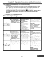
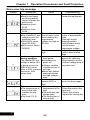
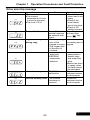
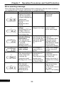
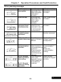
7-2 FAULT PROTECTION DISPLAY AND TROUBLESHOOTING ----------------- 91
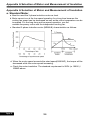
A. STANDARD MOTOR ------------------------------------------------------------------------ 96
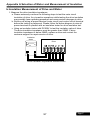
B.INSULATION MEASUREMENT OF DRIVE AND MOTOR ------------------------- 97
1. Measure the drive insulation impedance------------------------------------------- 97
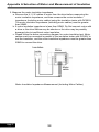
2. Measure the motor insulation impedance ----------------------------------------- 98
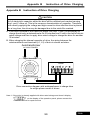
APPENDIX B INSTRUCTION OF DRIVE CHARGING ------------------------ 99
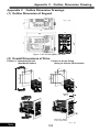
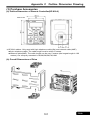
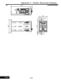
APPENDIX C OUTLINE DIMENSION DRAWINGS ------------------------- 100
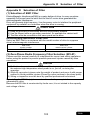
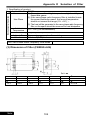
APPENDIX D SELECTION OF FILTER -------------------------------------- 103
vi
Chapter 1
Chapter 1
Cautions Before Installation
Cautions Before Installation
1-1 Product Verification
The product has passed the strictest quality test before shipped out from the
factory. However, the product might possibly sustain minor damages due to the
impact, shaking, vibration, and other factors during the transportation. Please
make sure to verify the following items after receiving this product. If the
product verification finds anything abnormal, please contact the agent
immediately for the further assistance.
1-1-1 Confirmation of Appearance
1.Check up the drive’s model number is identical with the shipping label on
the carton.
2.Check up the appearance of the drive for any paint chipped off,
smearing, deformation of shape, etc.
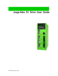
3.Check up the nameplate (as below figure) of the drive to verify the
product descriptions with the order specification.
Input Power Specs
Output Current & Capacity
Software Number
Product Serial Number
TYPE
RM6S1-20P2E1
INPUT
1PH AC200-240V 3A 50/60Hz
OUTPUT 3PH AC200-240V1.5A 0.1-400Hz
PGM NO.
0201-1
XXXXXXXX
SERIAL NO.
XXXXXXXXX
ISO 9001 IP20
Model Number
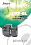
1-1-2 The description of nomenclature
RM6S1 – 2 0P2 E1
E1:Without Braking Transistor
Horse Power Code(see HP Table)
Input Voltage
2: AC 200~240V
Product Series
1-1-3 Confirmation of Accessories
One user manual is inclusive. Please verify other accessories inclusively
such as braking resistor, AC reactor, etc..
Code
Power
Horse Power
0P1
0.125 kW
0.17 HP
0P2
0.2 kW
0.25 HP
1
1
Chapter 1
Cautions Before Installation
1-2 Standard Specifications
1-2-1 Single-Phase 100V Series
Model name
(RM6S1-□□□□E1)
Maximum applicable motor
(HP/W)
20P1
20P2
0.17/125
0.25HP/200
400
600
Rated output capability (VA)
Rated output current (A)
Rated output voltage (V)
Range of output frequency
(Hz)
Power source (ψ, V, Hz)
Input current (A)
Permissible AC power source
fluctuation
Overload protection
Applicable safety standards
Cooling method
Protection structure
Weight (kg)
1
1.5
Three-phase 200~240V
0.1~400.00Hz
Single-phase, 200~240V, 50 / 60Hz
2
3
176V~264V 50/60 Hz ±5%
150% of drive rated output current for 1 min
Nature cooling
IP20
0.4
※Please refer to the standard specifications to verify the product specifications with
your requirements.
1
2
Chapter 1
Cautions Before Installation
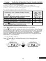
1-3 The Features of Control and Operation
Control method
Range of frequency
setting
Resolution
of frequency setting
Resolution
of output frequency
Control Characteristics
Overload protection
DC braking
Braking torque
0.1-400.00Hz
Operation panel: 0.01Hz(0.01~99.99Hz/100.0~400.0Hz)
Analog signal:0.06Hz/60Hz
0.01Hz
150% of drive rated output current for 1 minute
Start/stop braking time: 0~60.0sec
Stop braking frequency: 0.1~60Hz
Braking ability: 0~150% of rated current
About 20%
Acceleration /
Deceleration time
0sec(coast to stop), 0.0-3200.0sec(Indepensent setting of the
acceleration/deceleration. )
V/F pattern
V/F pattern (2 V/F points)
Square curve, 1.7th power curve, 1.5th power curve.
Output voltage adjustment of V/F pattern.(Variable voltage (V)
adjustment of V/F pattern for acceleration / deceleration)
Other functions
Frequency setting
signal
Operation Characteristics
Voltage vector sinusoidal PWM control(V/F control);
Switching frequency: 800Hz~16kHz
Operation signal
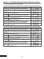
Multi-function inputs
Slip compensation, Auto-torque compensation,
Auto-adjustment for output voltage stability, Auto-operation for
energy-saving, Auto-adjustment of switching frequency,
Restart after instantaneous power failure, Over-torque
detection, DC braking, Counter function,
Modbus(RS-485)communication, Jump frequency,
upper/lower limits of output frequency,8-preset speeds,
S-curve acceleration/deceleration,
Temperature management, Parameters duplication.
Operation panel(including KP keypad ): ▲、▼
Analog signal: (DC 0-10V)/0~100%
Digital signal:Jog speed,8-preset speeds
Modbus(RS-485) communication
Operation panel(including KP keypad): RUN, STOP
Digital signal: FWD/REV rotation control
Modbus(RS-485) communication
3 programmable input terminals: X1-X3
Response time (1~255,unit 1ms)
Refer to the chapter of F_5.19~F_5.21 setting description.
Analog inputs
1 set of analog input: VI (0-10V)
Analog filter (0~255,unit 5ms),the dead band of analog
frequency, gain and bias are adjustable.
1
1
Chapter 2
Installation and Confirmation
Chapter 2
Installation and Confirmation
2-1 Basic Equipment
The drive needs the several components for the conjunctive operation. These
components are called “basic equipment”, listed in the following:
2-1-1 Power Source: The voltage only use for 200~240V.
2-1-2 MCCB or NFB: MCCB (Molded Case Circuit Breaker) or NFB (No Fuse
Breaker) can withstand the inrush current at instant power-on and
providing the overload and over-current protection to the drive.
2-1-3 Drive: The rated current of motors are different for the different pole or
rated voltage. Please base on the rated voltage and rated current of
motor to select drive. Do not select the drive only base on the horse
power specification of motor. (please refer to the lists of standard
specifications of drives)
2-1-4 Motor: The specifications of motor are determined from the requirement.
Please be cautious to the motor rated current that must not exceed the
drive current.
2-2 Environmental Conditions
For the safe operation of the drive, please be cautious to the environmental
conditions where the drive is going to be installed.
AC Power: AC power input must be complied with the AC power input
specification of the drive.(see RM6S1 standard specifications)
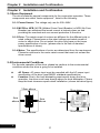
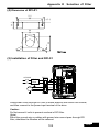
Location: Due to the heat dissipating requirement during the drive
operation, the drive must keep enough space for heat dissipation. Please
keep the least clearance space when installation. (shown as below figure)
10cm above
5cm
above
10cm above
5cm
above
10cm
above
10cm above
10cm above
2
2
Chapter 2
Installation and Confirmation
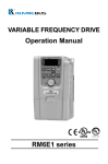
2-3 Basci Wiring
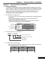
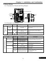
2-3-1 Descriptions of Terminal and Wiring Diagram
KP-601A/Modbus Port
Grounding
GND
AC power
source
input
VI
VR 1kΩ
1/4W
V+
COM
3Phase
Motor
(Open collector)
(DC 48V/50mA)
Motor
Y1
X3
X2
X1
2-3-2 Description of Terminals
Terminal of Main
Circuit
Type
Symbol
Function
Power
Source
L1,L2
AC power source input
terminals
Motor
U,V,W
Drive outputs to motor
terminals
Grounding
Grounding terminal
Description
For the single-phase power source
200V~240V.
The terminals output three phase
variable frequency and voltage to
motor.
Grounding resistance must be below
100Ω.
2-3-3 Control Terminals
Type
Control Circuit Terminal
Multi-function
input terminal
Multi-function
output terminal
Control power
Symbol
Function
X1
X2
X3
Input terminal 1
Input terminal 2
Input terminal 3
Y1
Output terminal 1
COM
Input/output common
ports
Short the detected parameter with
COM and set the function F5.26
The common port of input/output
control signal
V+
Power terminal for
control signal
DC+12 output. Maximum current
output 20mA
VI
Analog input terminal
DC 0~10V
GND
Common terminal for
analog input control
Common terminal for control power
(V+) and analog input
terminal(AI).
3
Description
Short the terminal of input with COM
and set the function F5.19~F5.21
2
Chapter 2
Installation and Confirmation
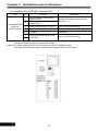
2-3-4 Modbus Port (RS-485)/ Keypad-601A
Type
Pin
Description
3
4
Auto-detect terminal of KP
2
Modbus(RS-485)
/KP601A
Communication
Function
Communication transmission
terminal (DX+)
Communication transmission
terminal (DX-)
Power terminal of KP (+13V)
1
5、6 Reversed
7
8
Modbus (RS-485) communication
uses pin1, 2.
Only for KP-601A linking
Only for KP-601A linking
Reversed
Common ports terminal of KP
power(0V)
Only for KP-601A linking
Note1: The terminal resistor (100Ω)slection is set by JPK1 (default setting : ON) and user has to
remove the frame to select the terminal resistor.
Note2: The cable material of KP-601A must be use CAT-5e 24AWG above.
The cable lenth must be within 5 meters( the longest lenth is 100 meters)
2
4
Chapter 2
Installation and Confirmation
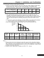
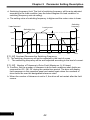
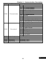
2-4 Wiring Cautions and Specifications
a.Wiring connection between drive and motor due to the variance of the rated
power causes the variance of the current leakage. The setting of the
switching frequency, rated power, and cable length is listed in the below table.
Cable length
10m
Seithching Frequency
20m
10kH*z 7.5kHz
30m
50m
100m
100m
above
5kHz
2.5kHz
800Hz
800Hz
The switching frequency setting is set by F1.21
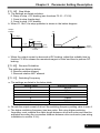
b.The cable length between the drive and motor must keep as short as
possible. The parasitic capacitance effect is minor within 10 meters. The
drive shall connect an AC reactor(ACL) on the side of drive output terminals
(U,V,W) and decrease the switching frequency if the motor cable is over
30m.
c.If the drive is used at the altitude over than 1000m, the relationship between
drive’s rated current and altitude are shown as below figure.
d.Recommended wire size and Molded Case Circuit Breaker(MCCB)
Percentage
of the rated 100%
current of
drive
90%
80%
70%
60%
0
1000
2000
3000
4000 Altitude (m)
Output
(U,V,W)
wire size
(mm²/AWG)
0.75~1.25
Grounding
wire size
(mm²/AWG)
3
Input
(R,S)
wire size
(mm²/AWG)
1.25/15
5
1.25/15
0.75~1.25
1.25/15
Model
no.
RM6S1
Input
current
(A)
MCCB
(A)
20P1
1.7
20P2
3
1.25/15
Note:
i. Please refer to the local electrical code with respect to the wiring(the loading
and continuity, the wire capability for the current and temperature, the length of
wiring, and the surrounding temperature must be all considered in order to add
or reduce the size of the wire).
ii. Please use the cable that is suitable for 600V, 75℃ above.
5
2
Chapter 3 The Setting of Operation Panel & Remote Controller
Chapter 3 The Setting of Operation Panel & Remote Controller
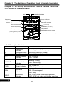
3-1 Function of Operation Panel
REV
Modbus/KP-601A
Power indicator
SPEC key indicator
Operation indicator
Frequency
Voltage
Current
Enter or leave
the function mode
RUN ( see F1.00)
Switch the function
group and number
UP/DOWN ( see F1.01)
STOP/RESET
Special function key
Set/Switch monitor mode
( Setting SPEC key function
see F1.17 and F1.18 )
Pot knob ( see F1.01 and F1.03)
3-1-1 Description of indicator
Symbol
Name
Explanation
Hz
Frequency
indicator
Indicating the unit of frequency
V
A
Voltage indicator
Current indicator
Indicating the unit of voltage
Indicating the unit of current
REV
Reverse rotation
indicator
ON: Reverse
OFF: Forward
KP/ModBus
KP-601A/ModBus
communication
indicator
Blinking: Linking
OFF: Non-linking
PWR
Power indicator
ON: Power ON
OFF: No power input
RUN
Operation
indicator
Blinking: Under acceleration or deceleration
ON: Constant speed
OFF: Stop
SPEC
Special key
indicator
ON: SPEC under self-holding operation
OFF: SPEC not under self-holding operation
3
6
Chapter 3 The Setting of Operation Panel & Remote Controller
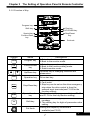
3-1-2 Function of Key
Program key
Run key
UP/DOWN key
Shift key
Special key
Function/Data
key
Stop/Reset
key
Pot knob
Symbol
Name
PROG
Program key
FUN
Function/Data
key
DATA
▲
▼
RUN
STOP
RESET
Up/Down key
Operation key
Stop/Reset key
SPEC
Special function
key
<<
Shift key
Pot Knob
Descriptions
1.Enter the function setting mode.
2.Back to the monitor mode.
1.Enter the parameter setting mode.
2.Back to the function setting mode.
3.Switch monitor mode.
Up/down key of changing functions and
parameters.
Drive start key.
1.Drive stops (all outputs cut off).
2.Fault reset.
3.Stop key can be set as the drive emergency
stop when the drive control is from the
external input terminals(see F1.05 for the
function setting).
This key function is programmable(see F1.17
and F1.18 for this key function setting).
1.Switch the function group and function
numbers.
2.The shifting key for digits of parameter value
setting.
Setting the frequency command is
available(see F5.00)
7
3
Chapter 3 The Setting of Operation Panel & Remote Controller
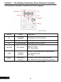
3-2 Fuctions of Remote Controller (KP-601A keypad)
Symbol
Name
Explanation
Hz
Frequency
indicator
V
Voltage indicator
Indicating the unit of voltage
A
Current indicator
Indicating the unit of current
KEYPAD
KP indicator
RUN
Operation
indicator
Blinking: Under acceleration or deceleration
ON: Constant speed
OFF: Stop
SPEC
Special key
indicator
ON: SPEC under self-holding operation
OFF: SPEC not under self-holding operation
Indicating the unit of frequency
Blinking: Linking
OFF: Non-linking
Note: When the drive is reversing that the frequency show negative number.
3
8
Chapter 3 The Setting of Operation Panel & Remote Controller
3-3 The Operation of Operation Panel and Monitor Mode
3-3-1 The Operation of Operation Panel
The operation of operation panel includes fault message and three modes. The
switching methods are shown as below figure:
Monitor mode
Function setting mode
PWR
SPEC
RUN
Hz
V
A
Parameter setting mode
FUN
PROG
Hz
V
A
PWR
SPEC
RUN
PROG
DATA
FUN
Hz
V
A
PWR
SPEC
RUN
DATA
STOP
RESET
PROG
Fault message
Hz
V
A
PWR
SPEC
RUN
The operation steps are shown in the below table (by default setting)
Operation Steps
Display
1.Start the drive and enter the main display.
Hz
V
A
PWR
SPEC
RUN
2.Press
PROG
key and enter the function setting mode.
Hz
V
A
PWR
SPEC
RUN
3.Press
FUN
DATA
key and enter the parameter setting mode.
Hz
V
A
PWR
SPEC
RUN
4.Press
FUN
DATA
key and return to the function setting mode.
Hz
V
A
PWR
SPEC
RUN
5.Press
PROG
key and return to the monitor mode.
Hz
V
A
PWR
SPEC
RUN
Fault message display:
Operation Steps
Display
The fault message displayed during the drive operation
1.Press
STOP
RESET
key and return to the monitor mode.
9
Hz
V
A
PWR
SPEC
RUN
Hz
V
A
PWR
SPEC
RUN
3
Chapter 3 The Setting of Operation Panel & Remote Controller
3-3-2 Monitor Mode
There are eight monitor modes can be selected in the monitor mode. User can
determine one of eight monitor modes as the main display on the operation panel.
And the monitor mode can be switched as shown in below figure:
Display 1
(Output Frequency)
Hz
V
A
Display 2
(Frequency Command)
FUN
PWR
SPEC
RUN
DATA
Hz
V
A
Display 3
(Output Voltage)
FUN
PWR
SPEC
RUN
DATA
Hz
V
A
PWR
SPEC
RUN
FUN
FUN
DATA
DATA
Display 8
(Default:MPM)
Hz
V
A
Display 4
(DC bus Voltage)
PWR
SPEC
RUN
Hz
V
A
PWR
SPEC
RUN
FUN
FUN
DATA
DATA
Display 7
(Default:Temperature of Heat Sink)
FUN
DATA
Hz
V
A
PWR
SPEC
RUN
Display
Display 6
(Default:Terminal Status)
Hz
V
A
Display 5
(Output Current)
FUN
DATA
PWR
SPEC
RUN
Hz
V
A
PWR
SPEC
RUN
Description
Display
Display1
(Main Display)
Hz: On (Output Frequency)
Hz
V
A
PWR
SPEC
RUN
Display2
Hz: On (Frequency Command)
Hz
V
A
PWR
SPEC
RUN
Display3
V: On (Output Voltage)
Hz
V
A
PWR
SPEC
RUN
Display4
V: On (DC bus Voltage)
Hz
V
A
PWR
SPEC
RUN
Display5
A: On (Output Current)
Hz
V
A
PWR
SPEC
RUN
Display6
Hz、A: On
(Default value: terminal status)
Hz
V
A
PWR
SPEC
RUN
Display7
V、A: On
(Default value: heat sink temperature)
Hz
V
A
PWR
SPEC
RUN
Display8
Hz、V: On (Default value MPM)
Hz
V
A
PWR
SPEC
RUN
※ Press
3
FUNC
DATA
key of the main display and switch to the mode (1~8)
10
Chapter 3 The Setting of Operation Panel & Remote Controller
a. Select one of eight monitor modes to be the main display and switch to the mode
FUN
(1~8) by DATA key in the monitor mode. The monitor mode setting can also be set
by F1.08.
b. User can basically determine which the display mode to be as the main display in
the monitor mode according to user’s demand. If user does not change the display
back the main display after the setting is completed, the drive will automatically
switch back to the main display after the operation panel is idle over 3 mins.
c. The display 6~8 are defined by F1.09~F1.11
3-3-3 The Status of Multi-function Terminals
The default setting of display 6 in the monitor mode is the status of multi-function
input terminals and the definition of each segment on the 7-segments display for 4
digits is shown as below figure:
Hz
V
A
PWR
SPEC
RUN
X1
X2
X3
Y1
The definition of display shown in the below table:
Display
Terminal
Status description
Hz
V
A
PWR
SPEC
RUN
X1
Multi-function input terminal “X1” is active.
Hz
V
A
PWR
SPEC
RUN
X2
Multi-function input terminal “X2” is active.
Hz
V
A
PWR
SPEC
RUN
X3
Multi-function input terminal “X3” is active.
Hz
V
A
PWR
SPEC
RUN
Y1
Multi-function output terminal is active.
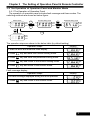
3-3-4 The Function Setting Mode
a.The selection of function group:
Operation Steps
1.Press
key in the monitor mode and enter function
group setting mode. The function group in the display will
be flashing.
Display
PROG
Hz
V
A
PWR
SPEC
RUN
2.Press ▲ key to increase the function group number.
Hz
V
A
PWR
SPEC
RUN
3.Press ▼ key to decrease the function group number.
See Chapter 4 – Parameter List for the setting range of
function groups.
Hz
V
A
PWR
SPEC
RUN
11
3
Chapter 3 The Setting of Operation Panel & Remote Controller
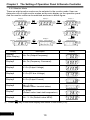
b.The function group / function number swapping:
Operation Steps
1.Press << key to swap to the function number setting
mode when function group is flashing.
2.Press << key to swap to the function group setting
mode when function number is flashing.
c.The selection of function number:
Operation Steps
1.Press << key to swap to the function number setting
mode after the function group is selected. And the
function number is flashing.
Display
Hz
V
A
PWR
SPEC
RUN
Hz
V
A
PWR
SPEC
RUN
Display
Hz
V
A
PWR
SPEC
RUN
2.Press ▲ key to increase the function number.
Hz
V
A
PWR
SPEC
RUN
3.Press ▼ key to decrease the function number. See
Chapter 4 – Parameter List for the setting range of
function numbers.
Hz
V
A
PWR
SPEC
RUN
Note: The grey-color digits in above tables represent the flashing of the digits.
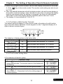
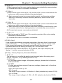
3-3-5 Parameter Setting Mode
The setting range of parameter is according to the function. The operation steps
are shown in the below table:
Operation Steps
1.The function setting mode: example F2.17(output
frequency).
2.Press
key in the function setting mode and enter
parameter setting mode.
3.Press << key to shift the digit; Example: Shift the
number to the last digit after the decimal point.
Display
Hz
V
A
PWR
SPEC
RUN
Hz
V
A
PWR
SPEC
RUN
Hz
V
A
PWR
SPEC
RUN
4.Press ▲ key to increase 0.1 to the output frequency.
Hz
V
A
PWR
SPEC
RUN
5.Press ▼ key to decrease 0.1 to the output frequency.
Hz
V
A
PWR
SPEC
RUN
Hz
V
A
PWR
SPEC
RUN
FUN
DATA
6.Press
FUN
DATA
key and return to function setting mode.
a.The digit of parameter value is flashing after the parameter value is changed.
(grey-color digits in above table means digit flashing)
b.The setting range of F2.17 is 0.00~400.00Hz
3
12
Chapter 3 The Setting of Operation Panel & Remote Controller
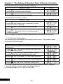
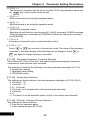
3-3-6 The Operation in the Monitor Mode
Frequency command, motor speed(RPM), machine speed(MPM) are
changeable in the monitor mode. For example of frequency command change,
the setting steps are shown in the following table.
The operation steps are shown in the below table:
Operation Steps
Display
1.In the monitor mode: Example: frequency command.
Hz
V
A
PWR
SPEC
RUN
2.Press
key to shift the digit of frequency command.
Hz
V
A
PWR
SPEC
RUN
3.Press << key to shift the digit of frequency command.
Example: Change the digit of decimal value.
Hz
V
A
PWR
SPEC
RUN
4.Press ▲ key to increase 1 to the frequency command.
Hz
V
A
PWR
SPEC
RUN
5.Press ▼ key to decrease 1 to the frequency command.
Hz
V
A
PWR
SPEC
RUN
<<
FUN
6.Press
key to save the setting value within 5 secs,
when completing setting of the rotation speed.
DATA
Note: grey-color digits in above table means digit flashing.
a.Use ▲ ▼ key to control the rotation speed in the monitor mode.
b.Press
key to save the setting value within 5 secs(the setting value is flashing),
when the required rotation speed is set. If the setting value is not saved, the display
will return to the monitor mode after 5 secs and save the value automatically after 3
mins. If the saving of the setting value is not completed and drive immediately
powers off within 3 mins, the setting value will recover to the original value before
setting.(see F1.07 for the setting).
FUN
DATA
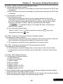
3-3-7 To Start/Stop the Drive
Press
RUN
and
STOP
RESET
key to control the output of drive. Shown as below:
Main display
(output frequency)
Main display
(output frequency)
RUN
Hz
V
A
PWR
SPEC
RUN
STOP
Hz
V
A
PWR
SPEC
RUN
RESET
13
3
Chapter 3 The Setting of Operation Panel & Remote Controller
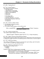
3-3-8 Save and Restore the Setting Value.
a.The operation steps of saving drive function setting are shown in the below table:
Operation Steps
1.Press
PROG
2.Press
mode.
<<
Display
key and enter the function setting mode.
key and switch to the function number setting
3.Press ▼ key to select F0.20.
4.Press
FUN
DATA
key and enter the parameter setting mode.
5.Press ▲ key and select the “SAv”.
FUN
6.Press
key to save settings. The display of operation
panel will display “End” after 2 secs.
7.After the panel displays ”End” for 1 sec, the display
automatically returns to the function setting mode.
8.Press
key and return to the monitor mode
(frequency command).
DATA
PROG
Hz
V
A
PWR
SPEC
RUN
Hz
V
A
PWR
SPEC
RUN
Hz
V
A
PWR
SPEC
RUN
Hz
V
A
PWR
SPEC
RUN
Hz
V
A
PWR
SPEC
RUN
Hz
V
A
PWR
SPEC
RUN
Hz
V
A
PWR
SPEC
RUN
Hz
V
A
PWR
SPEC
RUN
b.The operation steps of resuming drive function setting are shown in the below table:
Operation
Display
1.Press
PROG
2.Press
mode.
<<
key and enter the function setting mode.
key and switch to the function number setting
3.Press ▼ key to select F0.20.
4.Press
FUN
DATA
key to enter the parameter setting mode.
5.Press ▲ key and select the “rES”.
FUN
6.Press
key to save the setting. The panel will display
“End” after 2 secs.
7.After the panel displays ”End” for 1 sec, the display
automatically returns to the function setting mode.
8.Press
key and return to the monitor mode
(frequency command).
DATA
PROG
3
14
Hz
V
A
PWR
SPEC
RUN
Hz
V
A
PWR
SPEC
RUN
Hz
V
A
PWR
SPEC
RUN
Hz
V
A
PWR
SPEC
RUN
Hz
V
A
PWR
SPEC
RUN
Hz
V
A
PWR
SPEC
RUN
Hz
V
A
PWR
SPEC
RUN
Hz
V
A
PWR
SPEC
RUN
Chapter 4
Chapter 4
Parameter List
Parameter List
Group List (default value: F0.18=0)
Simple Parameter Group List (F0.18=0)
Group
Function
F0
System Parameters*(Simple)
F1
Control Setting( Simple)
Main Display Setting( Simple)
SPEC Key Setting
Stop Mode
Switching Frequency Setting( Simple)
F2
Frequency
Parameters
F4
Protection
Parameters
F5
Complete Parameter Group List (F0.18=1)
Group
F0
System Parameters
F1
Control Setting
Main Display Setting
SPEC Key Setting
Stop Mode
Switching Frequency Setting
Preset speed and jog
seed.
Acceleration/deceleration.
V/F pattern setting.
Upper/lower limits of
output frequency.
F2
Motor overload protection
F3
Multi-function Multi-function input
Parameters Multi-function output
Function
F4
F5
F6
15
Frequency
Parameters
Control
Parameters
Protection
Parameters
Preset speed.
Multi-acceleration/decelerati
on time.
V/F pattern setting.
Jump frequency.
Upper/lower limits of output
frequency.
Holding frequency and time.
Stall prevention setting.
Motor Slip compensation.
AVR compensation.
DC Breaking.
Drive operation after
instantaneous power failure.
Speed tracing.
Drive overload protection
Motor overload protection
Drive overheat protection
Fan control
Overload protection setting
Analog input
Multi-function input
Multi-function Multi-function output
Parameters UP/DOWN setting
Counting mode
Frequency detection
Special
parameters
Modbus communication
4
Chapter 4
Parameter List
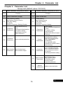
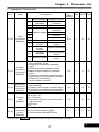
4-2 Complete Parameter Group List
F0 System Parameters
Func.
Name
Descriptions
0: Software version
1: Drive model number
2: Drive rated current
Drive
F0.00
Information 3: Drive running hours
4: Drive supply power time
5: Software checksum code
Parameter 0: Parameters are changeable
F0.01
Lock
1: Parameters are locked
Parameter
Set the password for the parameter
F0.02 Password
protection
Setting
Parameter
Unlock the passwords for the
F0.03 Password
parameters
Unlock
F0.04 Reserved Reserved
F0.05
F0.08
F0.09
F0.10
F0.11
F0.12
F0.13
F0.18
F0.19
F0.20
4
Power
Source
Fault
Record 1
Fault
Record 2
Fault
Record 3
Fault
Record 4
Fault
Record 5
Fault
Record 6
Parameter
Display
Selection
Reserved
Default
Setting
The value of setting according to the
actual power source
0: Fault code
1: Output current at drive fault
2: DC bus voltage at drive fault
3: Output frequency at drive fault
0: Simple parameter
1:Complete parameter
Range of
Setting
Unit
dF60
Page
─
─
─
33
0, 1
─
0
33
0~9999
1
0
33
0~9999
1
─
33
─
─
─
190.0~240
0.1V
.0
16
34
─
─
─
34
─
─
─
34
─
─
─
34
─
─
─
34
─
─
─
34
─
─
─
34
0
32
0,1
Reserved
0: Disable
CLF: Clear fault records
dF60: Default the factory setting of
60Hz
dF50: Default the factory setting of
50Hz
SAv: Store setting
rES: Resume setting
rdEE: Read the parameters from drive
to digital keypad
UrEE: Write the parameters from digital
keypad to drive
220.0
─
─
─
─
─
0
34
Chapter 4
Parameter List
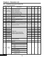
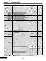
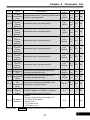
F1 Operation Parameters
Func.
Name
Descriptions
Unit
0~11
─
3
35
0~5
─
1
37
0~2
─
0
38
0~5
─
0
38
0, 1
─
0
38
dF60 Page
Start command
FWD or REV
command
FWD command
F1.00
F1.01
F1.02
F1.03
F1.04
Rotation direction
FWD or REV
0
command
1
REV command
FWD, REV
2
command
3 Operation panel
Forward
4
Reverse
Start
5
Reverse command
Command
6~7
Reserved
Reserved
Selection
Communication
Communication
8
control
Control
Communication
9
Reverse command
control
Communication
Forward
10
command
Control
Communication
11 Operation panel
Control
0: Frequency command by analog
input selection (F1.03).
1: Frequency command by operation
panel.
Primary
2: RPM command by operation panel
Frequency
3: Machine speed setting by operation
Command
panel.
Selection 4: Frequency command by multi-function
input terminal as UP/DOWN command.
5: Frequency command by
communication terminal.
Secondary 0: Frequency command by analog
input selection.
Frequency
1: Frequency command by operation panel.
Command 2: Frequency command by multi-function
Selection
input terminal as UP/DOWN command.
0: Pot knob+ VI
1: Pot knob –VI
Analog
2:VI – Pot knob
3: Pot knob or VI(switch by multi-function
Input
input terminal)
Selection
4: Pot knob
5: VI
“Pot knob”
Command 0: From drive’s operation panel.
Source
1: From external keypad(KP-601A).
Selection
Range
of
Setting
The color as
means functions can be set during the operation.
17
4
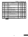
Chapter 4
Func.
Parameter List
Name
Validity of
STOP of the
F1.05
Operation
Panel
Frequency
Command
Selection
F1.06
(operation
panel)
Descriptions
Range of
Setting
Unit dF60 Page
0: Start command from the terminal,
STOP key disabled.
1: Start command from the terminal,
STOP key enabled.
0, 1
─
1
39
0: In the monitor mode, frequency
command cannot be changed.
1: In the monitor mode, frequency
command is changeable.
0, 1
─
1
39
0, 1
─
1
39
1~8
─
1
39
0~11
─
0
40
0~11
─
1
40
0~11
─
3
40
2~10
2P
4P
40
Frequency 0: In the monitor mode, the frequency
command cannot be stored.
Command
F1.07 Auto-Storing 1: In the monitor mode, the frequency
(operation
command can be stored
panel)
automatically after 3 minutes.
Control panel have 8 display option
1: Output frequency
2: Frequency command
Main Display 3: Output voltage
F1.08
Selection 4: DC bus voltage
5: Output current
6: Display mode 6 (F1.09)
7: Display mode 7 (F1.10)
8: Display mode 8 (F1.11)
F1.09
F1.10
F1.11
Display
Mode 6
Display
Mode 7
Display
Mode 8
Number of
Motor Poles
Machine
F1.13
Speed Ratio
Digits of
Decimal
F1.14
Value
(Machine
Speed)
F1.12
The color as
4
0: Terminal status
1: Temperature of heat sink
2: Motor rotation speed(RPM)
3: Machine speed(MPM)
4: Reserved
5: Reserved
6: Counting value
7: Current limit level
8: Primary frequency command
9: Secondary frequency command
10: Reserved
11: Reserved
Determination of RPM display value.
Set the ratio of machine speed. This
0.00~500.00 0.01 20.00
function determines MPM display value.
40
Select the digits of decimal values
displaying the machine speed.
40
0~3
means functions can be set during the operation.
18
─
0
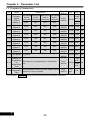
Chapter 4
Func.
Name
F1.17
SPEC Key
Setting
Descriptions
Same function as multi-function input
Parameter List
Range of
Unit
Setting
-28 ~ +28
dF60 Page
─
0
40
0, 1
─
0
40
0~2
─
0
41
0
41
*Note 3
F1.18
SPEC Key 0: Disable
Self-Holding
1: Enable
Function
F1.19
Stop Mode
1: Coast to stop
2: Coast to stop+ DC braking
F1.20
Reverse
Prohibition
0: Reverse rotation allowed
1: Reversal rotation NOT allowed
0, 1
─
F1.21
Switching
Frequency
The setting value is higher and the motor
noise is lower.
0~6
─
F1.22
Overload
Decrease
Switching
Frequency
0,1
─
1
44
0~16
1
0
42
0: Ramp to stop + DC braking
F1.23
41
0:The switching frequency will not be
adjusted by the load of current.
1: The swithching frequency will be
auto-adjusted according to the load of
current.
Number of Set the number of tolerance to drive fault
Tolerance to conditions when OC, faults are occurred
Drive Fault during the certain time period.
The color as
2
*Note 4
means functions can be set during the operation.
19
4
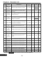
Chapter 4
Parameter List
F2 Frequency Parameters
Func.
Name
Primary
Speed
(Preset
Speed 1)
F2.00
Preset
Speed 2
Preset
Speed 3
Preset
Speed 4
Preset
Speed 5
Preset
Speed 6
Preset
Speed 7
Preset
Speed 8
F2.01
F2.02
F2.03
F2.04
F2.05
F2.06
F2.07
Range of
Setting
Descriptions
Multi-speed Multi-speed Multi-speed Multi-speed
level 4
level 3
level 2
level 1
command command command command
OFF
OFF
OFF
OFF
OFF
OFF
OFF
ON
OFF
OFF
ON
OFF
OFF
OFF
ON
ON
OFF
ON
OFF
OFF
OFF
ON
OFF
ON
OFF
ON
ON
OFF
OFF
ON
ON
ON
F2.16 Jog Speed Jog speed
Unit
dF60 Page
50.00
*Note 1
0.00~
43
0.01Hz
400.00
60.00
*Note 2
0.00~
400.00
0.00~
400.00
0.00~
400.00
0.00~
400.00
0.00~
400.00
0.00~
400.00
0.00~
400.00
0.00~
400.00
0.01Hz 10.00
43
0.01Hz 20.00
43
0.01Hz 30.00
43
0.01Hz 0.00
43
0.01Hz 0.00
43
0.01Hz 0.00
43
0.01Hz 0.00
43
0.01Hz 6.00
43
Reference
50.00
Frequency
*Note 1
The frequency corresponding to accel/decel
0.01~
F2.17
of
0.01Hz
44
time.
400.00
60.00
Accel/Decel
*Note 2
Time
Primary
The acceleration time of primary speed, preset
0.0~
0.1
F2.18 Acceleration
5.0
44
speed 5~8, and jog speed.
3200.0
sec
Time
The color as
4
means functions can be set during the operation.
20
Chapter 4
Func.
Name
Descriptions
Primary
The deceleration time of primary speed, preset
F2.19 Deceleration
speed 5~8, and jog speed.
Time
Acceleration
Time of
F2.20
Acceleration time of preset speed 2
Preset
Speed 2
Deceleration
Time of
F2.21
Deceleration time of preset speed 2
Preset
Speed 2
Acceleration
Time of
F2.22
Acceleration time of preset speed 3
Preset
Speed 3
Deceleration
Time of
F2.23
Deceleration time of preset speed 3
Preset
Speed 3
Acceleration
Time of
F2.24
Acceleration time of preset speed 4
Preset
Speed 4
Deceleration
Time of
F2.25
Deceleration time of preset speed 4
Preset
F2.26
F2.27
F2.28
F2.30
F2.31
Speed 4
Secondary
Multi-function input terminals select the
Acceleration
secondary acceleration time.
Time
Secondary
Multi-function input terminals select the
Deceleration
secondary deceleration time.
Time
Set S-curve
for
Set S-curve to slow the acceleration and
Accel/Decel deceleration at start and stop.
Time
Limitation of 0: Output voltage of V/F pattern is not limited.
Output 1: Output voltage of V/F pattern is limited
Voltage
(voltage compensation disabled).
0: Linear
1: Energy saving mode (auto-adjust V/F
V/F Pattern
according to the loads)
Selection 2: Square curve
3: 1.7th power curve
4: 1.5th power curve
The color as
Parameter List
Range of
Unit dF60 Page
Setting
0.0~
3200.0
0.1
sec
5.0
44
0.0~
3200.0
0.1
sec
5.0
44
0.0~
3200.0
0.1
sec
5.0
44
0.0~
3200.0
0.1
sec
5.0
44
0.0~
3200.0
0.1
sec
5.0
44
0.0~
3200.0
0.1
sec
5.0
44
0.0~
3200.0
0.1
sec
5.0
44
0.0~
3200.0
0.1
sec
5.0
44
0.0~
3200.0
0.1
sec
5.0
44
0.0~5.0
0.1
sec
0.0
45
0, 1
─
0
45
0~4
─
0
46
means functions can be set during the operation.
21
4
Chapter 4
Func.
F2.32
Parameter List
Name
Descriptions
Maximum
Output
Maximum output frequency of drive
Frequency
Range of
Setting
Unit
dF60
Page
50.0
0.1~400.0 0.1Hz
*Note 1
60.0
46
*Note 2
F2.33
F2.34
Starting Starting frequency of drive’s output
Frequency frequency.
Starting
Voltage
The voltage corresponds to the output
starting frequency.
0.1~10.0
0.1Hz
0.5
47
0.1~50.0
0.1V
8.0
47
50.0
Base
The frequency corresponds to the base
F2.35
0.1~400.0 0.1Hz
Frequency voltage in V/F pattern.
*Note 1
60.0
47
*Note 2
F2.36 Base Voltage
F2.37
F2.38
F2.39
The voltage corresponds to the base
frequency in V/F pattern.
V/F
Frequency at the first point of V/F
Frequency 1 pattern
V/F
Voltage at the first point of V/F pattern
Voltage 1
V/F
Frequency at the second point of V/F
Frequency 2 pattern.
220.0
47
0.0~399.9 0.1Hz
0.0
47
0.0~255.0
0.1V
0.0
47
0.0~399.9 0.1Hz
0.0
47
0.0~255.0
0.1V
0.0
47
0.1~255.0
0.1V
F2.40
V/F
Voltage at the second point of V/F
Voltage 2 pattern.
F2.42
Jump
Avoid mechanical resonance point 1.
Frequency 1
0.0~400.0 0.1Hz
0.0
48
F2.43
Jump
Avoid mechanical resonance point 2.
Frequency 2
0.0~400.0 0.1Hz
0.0
48
F2.44
Jump
Avoid mechanical resonance point 3.
Frequency 3
0.0~400.0 0.1Hz
0.0
48
0.0~25.5
0.1Hz
0.0
48
Jump
Set the range of the jump frequency 1,
F2.45 Frequency
2, 3.
Range
F2.47
Frequency The upper limit of output frequency
Upper Limit (1.00=maximum output frequency)
0.00~1.00
0.01
1.00
48
F2.48
Frequency The lower limit of output frequency
Lower Limit (1.00=maximum output frequency)
0.00~1.00
0.01
0.00
49
The color as
4
means functions can be set during the operation.
22
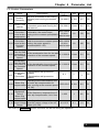
Chapter 4
Parameter List
F3 Control Parameters
Range of
Setting
Unit
dF60
Page
F3.00
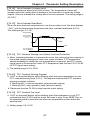
The drive accelerate to the holding
Holding
frequency and running at constant
Frequency
speed.
0.0~400.0
0.1Hz
0.5
50
F3.01
The drive runs at holding frequency
Holding Time
by constant speed and running the
Interval
time interval.
0.0~360.0
0.1sec
0.0
50
If stall is occurred during
30%~200%
acceleration, the motor keeps
running at the constant speed(200%: of drive
rated current
Off).
1%
170
50
Stall
Prevention If stall is occurred at constant speed 30%~200%
F3.04 Level at the running, the motor speed is
of drive
Constant decreased(200%: Off).
rated current
Speed
1%
160
50
Acceleration
Time for Stall
Set the acceleration time for the stall
0.1~3200.0 0.1sec
F3.05 Prevention at prevention of the constant speed.
the Constant
Speed
5.0
50
Deceleration
Time for Stall
Set the deceleration time at the stall
F3.06 Prevention at
0.1~3200.0 0.1sec
prevention of the constant speed.
the Constant
Speed
5.0
50
─
1
50
0.1Hz
0.0
51
Func.
Name
Stall
Prevention
F3.03 Level at the
Acceleration
F3.07
Descriptions
0: Deceleration stall prevention:
Deceleration Disabled
Stall
Prevention 1: Deceleration stall prevention:
Enabled
0, 1
According to the load condition, set
Motor Slip the motor slip compensation for
F3.09 Compensation motor running at the constant speed -59.9~60.0
(0.0: Off).
Frequency
Response
Set the frequency response time of
Time of
F3.10
motor slip compensation. Unit: 5ms
Motor Slip
Compensation
1~255
1
40
51
Automatic According to the load condition,
F3.12 Boost Voltage adjust the output voltage of the V/F
Range
Pattern (0.0: Off).
0.0~25.5
0.1
1.0
51
The color as
means functions can be set during the operation.
23
4
Chapter 4
Func.
Parameter List
Name
Descriptions
Response
Time of
Set the response time of automatic
F3.13
Automatic boost voltage range.
Boost Voltage
F3.18
Automatic
0: Disable
Voltage
Regulation 1: Enable
(AVR)
Range of
Setting
Unit
dF60
Page
1~255
1ms
60
52
0, 1
─
1
52
F3.19
Response Set the response time of automatic
Time of AVR voltage regulation.
0~255
1ms
50
52
F3.21
DC Braking
Set the current level of DC braking
Level
0~150%
of drive
rated current
1%
50
52
F3.22
DC Braking
Adjust the response time according
Response
to DC braking.
Time
1~255
1ms
10
52
Time Interval
Set the time interval for DC braking
F3.23 of DC Braking
before drive starts.
at Start
0.0~60.0
0.1sec
0.0
52
Time Interval
Set the time interval for DC braking
F3.24 of DC Braking
at drive stops.
at Stop
0.0~60.0
0.1sec
0.5
52
DC Braking
Active frequency level of DC
Frequency
braking at stop.
at Stop
0.1~60.0
0.1Hz
0.5
53
350~410
1Vdc
390
53
F3.25
Active Level DC bus voltage is over the setting.
of
Function disable setting:
F3.27 Overvoltage
100/200V series: 410
During
Deceleration
The color as
4
means functions can be set during the operation.
24
Chapter 4
Func.
Name
Descriptions
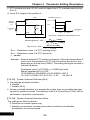
0: Drive cannot be restarted
1: Drive can be restarted
Operation 2: Ramp to stop (please refer to the
Selection at
F3.30
F3.31~F3.35)
Instantaneous
Power Failure 3: When the power is restored during
the ramp to stop interval, the drive
re-accelerates again
F3.31
The Voltage
Level Setting
at Power
Failure
Parameter List
Range of
Setting
Unit
dF60
Page
0~3
─
0
53
175.0
54
0.1Hz
3.0
54
Set the voltage level of power source
for ramp to stop. When the voltage of
150.0~192.0 0.1V
power input is lower than the setting
level, drive ramps to stop.
Subtracted
Frequency of When the power failure, the output
F3.32 Deceleration frequency = drive’s original output
at Power frequency - subtracted frequency.
Failure
0.0~20.0
F3.33
Deceleration
Set a deceleration time down to the
Time 1 at
turning frequency set in (F3.35).
Power Failure
0.0~3200.0 0.1sec
5.0
54
F3.34
Deceleration
Set a deceleration time below the
Time 2 at
turning frequency set in (F3.35).
Power Failure
0.0~3200.0 0.1sec
5.0
54
0.0~400.0
0.1Hz
0.0
54
1%
150
54
0.1~60.0
0.1sec
0.5
55
0~100%
1%
100
55
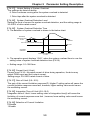
Set the turning frequency level at
Turning
power failure that the deceleration
F3.35 Frequency at
Power Failure time is switched from the F3.33
setting to the F3.34 setting.
F3.37
The Current
0~200%
When the current large than the
Level of
tracing current, the output frequency
of drive
Speed
is tracing downward.
rated current
Tracing
F3.38
Delay Time
Set the output delay time before the
for Speed
speed tracing.
Tracing
F3.39
The V/F
Pattern of
Speed
Tracing
The color as
Set the percentage of V/F output
voltage at the speed tracing.
means functions can be set during the operation.
25
4
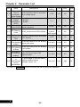
Chapter 4
Parameter List
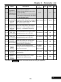
F4 Protection Parameters
Func.
F4.07
Name
Descriptions
0: Motor overload protection:
Disabled
Motor
1: Motor overload protection:
Overload
Enabled(OL)
Protection
2: Motor overload protection of
(OL)
independent cooling fans:
Enabled(OL)
Motor Rated Current setting according to the motor
F4.08
Current rated current.
Motor
No-Load
Current
Trip Time of
F4.10
Motor
Overload
Protection
Level of
F4.12
Drive
Overheat
F4.09
F4.13
Unit
dF60
Page
0~2
─
1
56
According
10%~150%
to the
of drive
0.1A
rated
56
rated current
current of
motor
1/3 motor
0~ motor
0.1A
rated
56
rated current
current
Set the tripped time of motor when
motor is overload(150% of Motor
rated current).
0.5~10.0
0.1min
5.0
56
Set the tripped level of drive when
drive is overheat.
85~115
1℃
90
56
0~3
─
2
56
0: Disable
1: Warning (OHt): Continuous
operation
Drive
(relay terminal outputs)
Overheat 2: Warning (OHt): Reduce switching
Pre-alarm
frequency operation
Selection
(relay terminal outputs)
3: Warning (OHt): Stop operation
(relay terminal outputs)
The color as
4
Current setting according to the
motor’s no-load condition
Range of
Setting
means functions can be set during the operation.
26
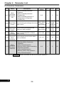
Chapter 4
Func.
Name
Descriptions
Range of
Setting
Parameter List
Unit
Drive Overheat Set the temperature level of
1℃
45~105
Pre-alarm Level warning alarm.
Set the temperature dead band of
Drive Overheat
0.1℃
F4.15
temperature warning and fan
0.1~10.0
Dead Band
active level.
F4.17
Reserved
Reserved
~
F4.19
PTC Overheat
Warning Level Set the temperature warning
F4.21
0.0~10.0 0.1Vdc
(Motor Overheat level(OH1) of PTC
Protection)
0: Warning (OH1): Continue
PTC
operation
Overheat
(relay terminal outputs)
F4.22
0, 1
─
Warning
1: Warning (OH1): Stop operation
Disposal
(relay terminal outputs)
PTC Overheat
F4.23
Set the overheat trip level of PTC
0.0~10.0
0.1V
Trip Level
System
0: Disable
Overload
F4.25
0, 1
─
Detection
1: Enable(OLO)
(OLO)
System
0: Detection during the constant
speed only
Overload
F4.26
0, 1
─
Detection
1: Detection during the running
Status
only
0: Drive is still running when the
Output Setting
overload is detected
F4.27
of System
0, 1
─
1: Drive is tripped when the
Overload
overload is detected
30%~200%
System
Set the level of the current for
F4.28
of drive
1%
Overload
overload detection
Detection Level
rated current
The output current is larger than
System
the setting F4.28 and exceeds the
F4.29
0.1~300.0 0.1sec
Overload
time interval of the overload
Detection Time
detection
30%~200%
Current Limit
F4.36
Current over current limit level
of drive
1%
(I-limit)
rated current
0.00~1.00 0.01
F4.37 Gain of I-limit Current limit control - P
Integration Time
0~10.0
F4.38
Current limit control - I
0.1
of I-limit
Selection of 0:Disable
0,1
F4.39
Current
─
1:Enable
Limitation
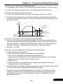
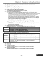
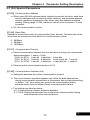
F4.14
The color as
dF60 Page
70
56
3.0
57
1.2
57
0
57
2.4
57
0
58
0
58
0
59
160
59
0.1
59
180
59
0.10
59
0.6
59
0
59
means functions can be set during the operation.
27
4
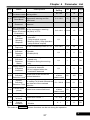
Chapter 4
Parameter List
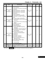
F5 Multi-function Parameters
Func.
Range of
Setting
dF60
Page
“Pot knob”
Selection
F5.00
(Analog
Input)
1
60
F5.01
1
60
1
61
1.00
61
0.00
61
1.00
61
0.00
61
20
62
0.00
62
5.0
62
5.0
63
F5.02
F5.03
F5.04
F5.05
F5.06
F5.07
F5.08
F5.09
Name
Descriptions
Unit
0: Analog input gain
1: Frequency command
0~3
─
2: Current limit
3: Variable voltage of V/F pattern
0: Analog input gain
VI Selection 1: Frequency command
(Analog 2: Current limit
0~4
─
Input)
3: Variable voltage of V/F pattern
4: PTC temperature
VI Input
0: 2~10V
Source
0, 1
─
1: 0~10V
Selection
Pot Gain
(Analog Analog input of “Pot knob” gain
0.00~2.00 0.01
Input)
“Pot knob”
Bias
Analog input of “Pot knob” bias
-1.00~1.00 0.01
(Analog
Input)
VI Gain
(Analog Analog input of VI gain
0.00~2.00 0.01
Input)
VI Bias
(Analog Analog input of VI bias
-1.00~1.00 0.01
Input)
Filter Setting
Filter the signal based on analog input
of Analog
0~255
─
setting.
Frequency
When signal noise is large,
Analog
appropriately increase the dead band
Frequency
0.00~2.55 0.01Hz
to stabilize the frequency. But this will
Dead Band
reduce the tuning linearity.
Acceleration Set the acceleration time of the variable
0.0~3200.0 0.1sec
Time of V/F voltage of V/F pattern.
Deceleration Set the deceleration time of the variable
F5.10
0.0~3200.0 0.1sec
Time of V/F voltage of V/F pattern.
The color as
4
means functions can be set during the operation.
28
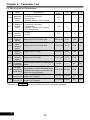
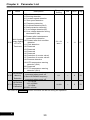
Chapter 4
Func.
F5.19
F5.20
F5.21
F5.25
Name
Descriptions
Range of
Setting
0: Disable
±1: Jog command
±2: Secondary accel/decel command
switching
Multi-function
-28 ~ +28
±3: Multi-speed level 1 command
Input
*Note 3
±4: Multi-speed level 2 command
Terminal X1
±5: Multi-speed level 3 command
±6: Reserved
±7: Reset command
±8: External fault command(EF)
±9: Interruption of output command
(bb)
±10: Coast to stop command(Fr)
Multi-function ±11: Speed search from the maximum
-28 ~ +28
frequency
Input
*Note 3
Terminal X2 ±12: Speed search from the frequency
setting
±13: Holding command
±14: UP command
±15: DOWN command
±16: Clean UP/DOWN frequency
command
±17: UP/DOWN command enter key
±18: Analog input source selection
(Pot knob/AI)
±19: Primary and secondary
frequency command option
Multi-function ±20: Reserved
-28 ~ +28
Input
±21: Reserved
*Note 3
Terminal X3 ±22: Forward command
±23: Reverse command
±24: Stop command with 3-wire
start/stop circuit
±25: DC braking enable (Stop)
±26: Counter input
±27: Counter clear
±28: Current limit enable
Digital Input When the input signal is less than the
Response setting time, program will not be
1~255
Time
activated.
The color as
Parameter List
Unit
dF60
Page
─
22
63
─
23
63
─
1
63
5ms
10
58
means functions can be set during the operation.
29
4
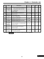
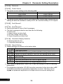
Chapter 4
Func.
Name
Parameter List
Descriptions
0: Disable
±1: Running detection
±2: Constant speed detection
±3: Zero speed detection
±4: Frequency detection
±5: Overload detection(OLO)
±6: Stall prevention detection
±7: Low voltage detection(LE)
±8: Over voltage detection during
deceleration (db)
±9: Restart after instantaneous
power failure detection
Multi-function
±10: Restart after fault condition
Output Setting
F5.26
detection
of Ta/Tc
±11: Fault detection
Terminals
±12: Reserved
±13: Reserved
±14: Reserved
±15: Reserved
±16: Detection of counter value1
±17: Detection of counter value2
±18: Reverse detection
±19: NTC temperature warning
detection (OHt)
±20: Reserved
±21: PTC temperature warning
detection (OH1)
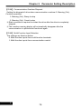
0: Erase UP/DOWN frequency
UP/DOWN
command when power off
F5.30
Memory
1: Store UP/DOWN frequency
Selection
command when power off
0: 0.01Hz
UP/DOWN
1~8: × 0.05Hz
F5.31 Frequency
9: 0.5Hz
Calibration
10~250: × 0.1Hz
The color as
4
Range of
Setting
Unit
dF60
Page
─
11
67
0, 1
─
0
70
0~250
─
0
70
-21~+21
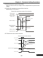
*Note 3
means functions can be set during the operation.
30
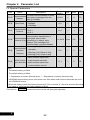
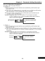
Chapter 4
Func.
Name
Descriptions
1~5: Terminal adjust the response
time. Continuous acceleration or
UP/DOWN
F5.32 Calibrating
deceleration when over the
Time
setting time
6: Edge trigger
F5.33
UP/DOWN
Adjust UP/DOWN frequency on
Frequency keypad directly
Adjustment
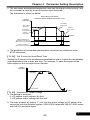
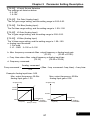
F5.35
Counting
Mode
0: Up counting mode
1: Down counting mode
F5.36
Counter
Value 1
F5.37
Counter
Value 2
F5.39
Constant
Speed
Detection
Range
F5.40
F5.41
Parameter List
Range of
Setting
Unit
dF60
Page
1~6
─
1
70
0.00
71
0.00~400.00 0.01Hz
0, 1
─
0
71
Set counter value 1 for sequential
operation control cycle
0~9999
1
0
71
Set counter value 2 for sequential
operation control cycle
0~9999
1
0
71
Set the bandwidth of constant speed
detection range
0.0~10.0
0.1Hz
2.0
72
Frequency
Set the bandwidth of frequency
Detection
detection range
Range
0.0~10.0
0.1Hz
2.0
72
Frequency
Set the frequency detection level of
Detection
multi-function terminal
Level
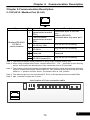
0.0~400.0
0.1Hz
0.0
72
The color as
means functions can be set during the operation.
31
4
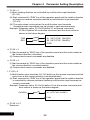
Chapter 4
Parameter List
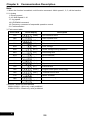
F6 Special Parameters
Func.
Name
Descriptions
The host uses the address to send
Communication
F6.55
and receive messages from the
Address
drive (0: Disable)
0: 4800bps
F6.56
Baud Rate 1: 9600bps
2: 19200bps
F6.57
0: 8,N,2
Communication
1: 8,E,1
Protocol
2: 8,O,1
When the data transmission during
communication transmission is
Communication interrupted, has no data
F6.58 Overtime (Cot) transmitting, or delays, drive
displays “Cot” message (0.0:
Communication overtime disable)
0: Warning (Cot): Continue
Communication
operation.
F6.59
Overtime
1: Warning (Cot): Ramp to stop
Disposal
2: Warning (Cot): Coast to stop
Range of
Setting
Unit
dF60
Page
0~254
─
0
73
0~2
─
1
73
0~2
─
1
73
0.0
73
0.0~100.0 0.1sec
0~2
─
0
74
0, 1
─
0
74
0: Multi-function inputs from
multi-function terminals
Multi-Function
F6.60
Input Selection 1: Multi-function inputs from
communication control
(Note):
1. The default setting of 50Hz
2. The default setting of 60Hz
3. + : Represents a contact (Normal open), ─ : Represents b contact (Normal close)
UP/DOWN control wiring must not exceed over 20m when multi-function terminals are used
for UP/DOWN control.
4. When the setting value of switching frequency(F1.21) exceeds “4”, the drive must be de-rating
for usage or selecting the higher capacity of drive.
The color as
4
means functions can be set during the operation.
32
Chapter 5
Parameter Setting Description
Chapter 5 Parameter Setting Description
5-1 (F0) System Parameters
【F0.00】 Drive Information
a. The function can display the horse power and software version. Check if the
capacity of drive corresponding to the drive by this function.
b. This manual and software version must be identical.
The drive with different software version cannot duplicate drive parameters, or
the drive operation panel will display Wr_F.
c. The descriptions of LED indicators shows the different displays of the operation
panel, and LED indicator displays are shown as below table.
d. The left 2th bits of drive model number for 200V single-phase series displays ”S”.
Hz
○
●
○
●
○
●
V
○
○
●
●
○
○
A
○
○
○
○
●
●
Software version
Drive model number
Drive rated current
Drive running hours
Drive supply power time(Hours)
Software checksum code
【F0.01】 Parameter Lock
a. Protect the parameter settings to prevent parameter settings from unexpected
adjustments causing the system operated incorrectly.
b. The parameter setting as the following
0: Parameters are changeable
1: Parameters are not changeable
c. After locking the parameters, the user can not change the password by F0.02.
【F0.02】 Parameter Password Setting
a. Preventing any unqualified personnel from setting the invalid parameters.
b. To protect the parameter settings, select function F0.02 and set the protection
password of parameters.
After setting the password by number 1~9999, the operation panel displays
Parameters cannot be changed after setting the passwords.
.
【F0.03】 Parameter Password Unlock
a. Select the function F0.03 to disable the parameter password setting (F0.02).
If the input passwords are correct, the operation panel displays “
“.
When user inputs wrong parameter passwords, the panel will display “
” at
1st time; and then display “
”(PWF2) at 2nd time, and display
“
”(PWF3) at 3rd time.
b. If user inputs wrong parameter passwords for 3 times, the drive must be power
off and restart to re-begin the password decoding process.
33
5
Chapter 5
Parameter Setting Description
【F0.04】 Reserved
【F0.05】 Power Source
a. The power source setting as the following table
Power source specification
100V series
200V series
400V series
Range
100.0~120.0V
190.0~240.0V
340.0~480.0V
b. The power source setting must be according to the actual power source and the
setting will affect the activation validity of LE, LE1 and the validity of V/F outputs.
【F0.08】 Fault Record 1
|
|
【F0.13】 Fault Record 6
a. Record the latest 4 times of fault messages.
b. The fault messages selection are listed as the following:
0: Fault code
1: Output current at drive fault
2: DC bus voltage at drive fault
3: Output frequency at drive fault
【F0.18】 Parameter Display Selection
0: Simple parameter list
1: Complete parameter list
【F0.20】 Default Setting
a. Default settings are shown as the below table:
Disable
Clear fault records
Default the factory setting of 60Hz (All SAv setting will be clear)
Default the factory setting of 50Hz (All SAv setting will be clear)
Store setting
Resume setting
Read the parameters from drive to digital keypad
Write the parameters from digital keypad to drive
b. After setting all parameters, select SAv to save all settings in case for restoring
parameters.
c. For parameter duplication, KP-601A must be connected to the drive when rdEE
and UrEE parameters for parameter duplication are used. This also can be
applied for parameter duplication of multiple drives to save the setting time.
5
34
Chapter 5
Parameter Setting Description
5-2 (F1) Operation Parameters
【F1.00】 Start Command Selection
a. F1.00 = 0
(I) Motor forward and reverse directions are controlled by multi-function input
terminals(X1~X3).
(II) Start and motor rotating direction commands are controlled by multi-function
input terminals(X1~X3) for forward and reverse command.
(III) The motor stops running when the multi-function input terminals are set
(closed) or open simultaneously.
Example: Parameter value: F5.19=22 (define X1 as forward command),
F5.20=23 (define X2 as reverse command) and the drive control is
shown as the below diagram.
X1 (OFF:STOP ON:FWD RUN)
X2 (OFF:STOP ON:REV RUN)
FWD RUN/STOP
REV RUN/STOP
COM
b. F1.00 = 1
(I) Motor forward and reverse directions are controlled by multi-function input
terminals (X1~X3).
(II) Start command by forward command (defining X1~X3 as forward command)
and motor rotating direction by reverse command (defining X1~X3 as reverse
command).
Example: Parameter value: F5.19=22(define X1 as forward command),
F5.20=23(define X2 as reverse command) and the drive control is
shown as the below diagram.
X1 (OFF:STOP ON:RUN)
X2 (OFF:FWD ON:REV)
RUN/STOP
FWD/REV
COM
35
5
Chapter 5
Parameter Setting Description
c. F1.00 = 2
(I) Motor rotating direction are controlled by multi-function input terminals
(X1~X3).
(II) Start command by “RUN” key of the operation panel and the rotation direction
by forward or reverse command defined by multi-function input terminals
(X1~X3).
(III) The motor stops running when the multi-function input terminals
(forward/reverse commands) are set closed or open simultaneously.
Example: Parameter value: F5.19=22(define X1 as forward command),
F5.20=23(define X2 as reverse command) and the drive control is
shown as the below diagram.
X1 (OFF:STOP ON:FWD)
X2 (OFF:STOP ON:REV)
FWD
REV
COM
d. F1.00 = 3
(I) Start command by “RUN” key of the operation panel and the motor rotates at
the forward direction (clockwise).
(II) Forward and reverse commands are disabled.
e. F1.00 = 4
(I) Start command by “RUN” key of the operation panel and the motor rotates at
the reverse direction (counterclockwise)
(II) Forward and reverse commands are disabled.
f. F1.00 = 5
(I) Multi-function input terminals (X1~X3) define as the reverse command and the
motor runs at the reverse direction (counterclockwise).
(II) Start command by “RUN” key of the operation panel and the rotation direction
is controlled by reverse command (defining multi-function input terminals as
reverse command).
Example: Parameter value: F5.19=23 (define X1 as the reverse command) and
drive control is shown as the below diagram
X1 (OFF:FWD ON:REV)
FWD/REV
COM
g. F1.00 = 6~7
Reserved
5
36
Chapter 5
Parameter Setting Description
h. F1.00 = 8
(I) Start command and the motor rotating direction are controlled by communication.
(II) Forward and reverse commands are disabled.
i. F1.00 = 9
(I) Multi-function input terminals(X1~X3) define as the reverse command and the
motor runs at the reverse direction (counterclockwise).
(II) Start command is given by communication control, and the motor rotating
direction is defined by reverse command (defined by multi-function input
terminals).
j. F1.00 = 10
(I) Multi-function input terminals(X1~X3) define as the reverse command and the
motor runs at the reverse direction (counterclockwise).
(II) Start command is given by forward command (defined by multi-function input
terminals) and the motor rotating direction is controlled by communication.
(III) Forward and reverse commands are disabled.
k. F1.00 = 11
(I) Start command by “RUN” key of the operation panel and the motor rotating
direction by communication.
(II) Forward and reverse commands are disabled.
※F1.00 = 0 or 2
If the forward and reverse commands are active at the same time, the operation
panel will display “------“ along with inter-flashing display value at monitor mode.
If the forward and reverse commands are set (closed) simultaneously, the
operation panel will be flashing to display “dtF” in the monitor mode.
※When the motor rotation direction is set to reverse, the output frequency will
display “-“ and the reversed indicator will ON.
【F1.01】 Primary Frequency Command Selection
a. F1.01 = 0
The frequency is controlled by analog input terminal (select the analog input
source: “Pot knob”, VI by defining function F1.03)
(I) “Pot knob”:
For the gain and bias ranges of frequency settings, please refer to functions
F5.03 and F5.04.
(II) VI-GND:
For the gain and bias ranges of frequency settings, please refer to functions
F5.05 and F5.06.
Select the input mode by JP1
JP1I mode:
The range of input current is 4~20mA or 0~20mA (selection by function F5.02)
JP1V mode:
The range of input voltage is 2~10V or 0~10V (selection by function F5.02)
37
5
Chapter 5
Parameter Setting Description
b. F1.01 = 1
The frequency command can be set by function F2.00 using operation panel and
by ▲ ▼ key in the monitor mode as well.
c. F1.01 = 2
RPM command is set using the operation panel.
d. F1.01 = 3
MPM command is set using the operation panel.
e. F1.01 = 4
UP/DOWN command control.
Selection by multi-function input terminal X1~X4(UP command, DOWN command,
Clear the frequency command by UP/DOWN, Confirm the frequency command
by UP/DOWN).
f. F1.01 = 5
Frequency command is set by communication control.
※ F1.01 = 1~3
Press ▲ or ▼ key one time in the monitor mode. The value of the frequency
command in the panel display will be blinking but not changed. Press ▲ or
▼ key again to change frequency command.
【F1.02】 Secondary Frequency Command Selection
Set functions F5.19~F5.22 as ±19, and switch the primary/secondary frequency
command by multi-function input terminals.
The settings are listed as the following: (see the parameter description of F1.01)
0: Analog input setting
1: Operation panel setting
2: UP/DOWN setting
【F1.03】 Analog Input Selection
The settings are listed as below: (see the parameter description of F5.00~F5.01)
0: “Pot knob”+VI
1: “Pot knob”-VI
2: VI-“Pot knob”
3: “Pot knob” or VI (switched by multi-function input terminals)
4: “Pot knob”
5: VI
※ “Pot knob” is on the operation panel, and AI is the analog input terminal.
【F1.04】“Pot knob” Command Source Selection
The settings are listed as below:
0: From drive’s operation panel.
1: From external keypad (KP-601A).
5
38
Chapter 5
Parameter Setting Description
【F1.05】 Validity of STOP of the Operation Panel
a. The settings are listed as below:
0: When the start command is controlled by multi-function terminal, the STOP key
is disabled.
1: When the start command is controlled by multi-function terminal, the STOP key
is enabled.
b. The operation of STOP key
(I) For emergency stop:
When the start command and the motor rotating direction of drive are
controlled by multi-function input terminal (F1.00=0, 1 or 10), press “STOP”
key on the operation panel during the drive operation and the drive output
frequency will drop to 0.00Hz, and the operation panel will display
. To restart the drive is to release the start command and
restart the drive again.
(II) For drive stop (natural stop):
Hz
V
A
PWR
SPEC
RUN
When F1.00=2, 3 or 4, 11, start command is active by
command is active by
STOP
RESET
RUN
key; stop
key.
【F1.06】 Frequency Command Selection (operation panel)
The settings are listed as below:
0: The frequency command cannot be changed in the monitor mode to avoid the
fault occurred by changing the frequency in the monitor mode.
1: The frequency command can be changed in the monitor mode.
【F1.07】 Frequency Command Auto-Storing (operation panel)
The settings are listed as below:
0: The frequency command setting does not auto-store in the monitor mode.
1: The frequency command setting is auto-stored after 3 minutes in the monitor
mode.
【F1.08】 Main Display Selection
a. The settings are listed as below:
1: Output frequency
2: Frequency command
3: Output voltage
4: DC bus voltage
5: Output current
6: Display mode 6 (F1.09)
7: Display mode 7 (F1.10)
8: Display mode 8 (F1.11)
b. Above display modes can be selected as the primary display and other display
modes becomes secondary display modes.
c. When the drive is idle without any operation for 3 minutes, the secondary display
will be automatically changed to the primary display mode.
39
5
Chapter 5
Parameter Setting Description
【F1.09】 Display Mode 6
|
|
【F1.11】 Display Mode 8
The settings are listed as below:
0: Terminal status
1: Temperature of heat sink
2: Motor rotation speed(RPM)
3: Machine speed(MPM)
4: Reserved
5: Reserved
6: Counting value
7: Current limit level
8: Primary frequency command
9: Secondary frequency command
10: Reserved
11: Reserved
【F1.12】 Number of Motor Poles
a. The settings are listed as below:
2P, 4P, 6P, 8P, 10P
b. The rotation speed display in the monitor mode
Motor speed(RPM)
120
Motor poles number(F1.12)
Output f requency
【F1.13】 Machine Speed Ratio
The machine speed display in the monitor mode
Machine speed = Machine speed ratio (F1.13) × Output frequency
【F1.14】 Digits of Decimal Value (Machine Speed)
Set the digits of decimal values (the range from 0~3 digits behind the decimal point)
to display the higher resolution of machine speed for observation of machine speed.
【F1.17】 SPEC Key Setting
The setting of SPEC key is similar as multi-function input setting; see the function
F5.19 ~ F5.21 for SPEC key setting reference.
【F1.18】 SPEC Key Self-Holding Function
SPEC key self-holding function
0: Disable
1: Enable
Example: SPEC key is set as reverse command.
●Start command(F1.00) is set as 5 (Start the drive by operation panel)
●Set function F1.17 as 23 (reverse command)
●Set function F1.18 as 1 for holding operation and press “SPEC” key
during the drive operation, and motor will run in reverse direction.
5
40
Chapter 5
Parameter Setting Description
【F1.19】 Stop Mode
a. The settings are listed as below:
0: Ramp to stop + DC braking (see functions F3.21 ~ F3.35)
1: Coast to stop (inertia stop)
2: Coast to stop + DC braking
b. When F1.19=2, the stop operation is shown in the below diagram:
Output
voltage
N
10
AC voltage
F3.22
DC voltage
F3.38
1
F3.21
Time
Max. freq./10
F3.24*N
Max. frequency
Output
frequency
Stop
c. When the output current is abnormal at DC braking, adjust the suitable time by
function F3.38 to release the remained magnet of rotor and then to perform DC
braking.
【F1.20】 Reverse Prohibition
The settings are listed as below:
0: Reverse rotation allowed
1: Reversal rotation NOT allowed
【F1.21】 Switching Frequency
a. The settings are listed in the below table:
Setting Value
0
1
2
3
4
5
6
Switching frequency
800Hz
2.5kHz
5kHz
7.5kHz
10kHz
12.5kHz
16kHz
b. De-rate the output current of drive if the switching frequency setting value is over 4.
c. The higher switching frequency has less noise. But using higher switching
frequency must consider the cable length between drive and motor and must be
adjusted according the connection distance between drive and motor (see wiring
installation in section 2-3-4)
41
5
Chapter 5
Parameter Setting Description
d. Switching frequency limit: The limit of switching frequency will be auto-adjusted
according to the load condition (see the below diagram for load condition vs.
switching frequency auto-de-rating).
e. The setting value of switching frequency is higher and the motor noise is lower.
Load current
Switching
frequency
Load current
Switching freq.
16K
100%
5%
12.5K
90%
10K
80%
7.5K
1min
1min
1min
1min
1min
1min
Time
【F1.22】Overload Decrease the Switching Frequency
0:The switching frequency will not be adjusted by the load of curren
1: The swithching frequency will be auto-adjusted according to the load of current.
【F1.23】 Number of Tolerance to Drive Fault (Maximum :0~16 times)
a. Function: Set the number of tolerance to drive fault conditions when faults are
occurred for OC, OE, GF during the certain time period. The drive will display
fault message on the operation panel and restart again when the numbers of
drive faults are over the designated tolerance value.
b. When the number of tolerance is set to 0, the drive will not restart after the fault
occurs.
5
42
Chapter 5
Parameter Setting Description
5-3 (F2) Frequency Parameters
【F2.00】 Primary Speed (Preset Speed 1)
|
|
【F2.07】 Preset Speed 8
【F2.16】 Jog Speed
a. Setting range: 0.00~400.00Hz
b. The settings are listed as below:
(I) Set the acceleration / deceleration time of multi-speed (F2.18~ F2.28)
(II) Set multi-function input terminals(F5.19~ F5.22)
c. Preset speed table
Jog
Multi-speed Multi-speed Multi-speed Multi-speed
speed
level 4
level 3
level 2
level 1
command command
command
command
command
ON
×
×
×
×
Name
Jog speed
OFF
OFF
OFF
OFF
OFF
OFF
OFF
OFF
ON
Primary Speed
(Preset Speed 1)
Preset Speed 2
OFF
OFF
OFF
ON
OFF
Preset Speed 3
OFF
OFF
OFF
ON
ON
Preset Speed 4
OFF
OFF
ON
OFF
OFF
Preset Speed 5
OFF
OFF
OFF
OFF
ON
ON
OFF
ON
ON
OFF
Preset Speed 6
Preset Speed 7
OFF
OFF
※ “×”: Don’t care.
ON
ON
ON
Preset Speed 8
OFF
※Jog speed has the highest priority. That is, when the jog speed is on, all other
speed command are void.
※Jog speed and the multi-speed commands programmed by functions F5.19~
F5.22 to define multi-function input terminals (X1~X3) are given by input signals
ON and OFF to the multi-function input terminals.
※ON: “a” contact (normal open) is set and “b” contact (normal close) is open.
OFF: “a” contact (normal open) is open and “b” contact (normal close) is set.
d. Multi-speed and acceleration/deceleration time
43
5
Chapter 5
Freuqency
Parameter Setting Description
Primary
acc. time
Primary Primary
acc. time acc. time
Preset
speed 7
Acc. time Primary
of preset acc. time
Preset
speed 6
speed 4
Preset
speed 5
Dec. time
Preset
Acc. time of preset
speed 4
of preset speed 3
speed 2
Preset
Primary
speed 2
acc. time
Primary
speed
Preset
speed 3
Preset
speed 8
Primary
dec. time
Jog speed
Time
Multi-speed
level 1
Multi-speed
level 2
Multi-speed
level 3
Jog command
※The above illustration is an example of preset speed 1~8. The acceleration /
deceleration time of preset speed 5~8 and jog speed are depend on the setting of
primary acceleration / deceleration time.
※When the drive stops, and the jog command is ON, the motor is running at the jog
speed – no start command is required.
※The analog input terminals (“Pot knob”, Vl) are disabled at multi-speed setting
(primary speed excluded).
※As for the accel/decel time, please see the parameter setting (F2.18~ F2.28).
【F2.17】 Reference Frequency of Acceleration/Deceleration Time
Set the corresponding frequency of accel/decel time.
The setting range: 0.01~400.00Hz
【F2.18/F2.19】 Primary Acceleration / Deceleration Time
|
|
【F2.24/F2.25】 Acceleration / Deceleration Time of Preset Speed 4
【F2.26/F2.27】 Secondary Acceleration / Deceleration Time
a. The acceleration/deceleration time of preset speed is the time that the frequency
starting from 0Hz accelerates to the reference frequency of acceleration/deceleration
time (F2.17). Multi-speed command can control the multi-speed and acceleration/
deceleration time of preset speeds. The setting range: 0.0~3200.0 sec.
b. The acceleration/deceleration time setting of primary speed, preset speed 5 ~
preset speed 16, and jog speed are set by primary acceleration/deceleration time
(F2.18/F2.19).
5
44
Chapter 5
Parameter Setting Description
c. The secondary acceleration/deceleration time has the higher control priority, and
the command is input by the multi-function input terminals.
The illustration is shown as below:
Secondary accel./decel.
switching and prohibited command curve
Output
frequency
Secondary
decel. time
Max. output
frequency
Primary
decel. time
Secondary
accel. time
Primary
accel. time
Time
Switch between the
secondary accel./decel.
(Multi-function input terminal)
Holding command
(Multi-function input terminal)
d. The prohibition of acceleration/deceleration command are ineffective at the
STOP command.
【F2.28】 Set S-curve for Accel/Decel Time
Setting the S-curve for the acceleration/deceleration time is to slow the acceleration
and deceleration time at start and stop. For example: To ease the impact of the
fallen object on the conveyor line or elevator.
Output
frequency
Frequency
command
S-curve time
Time
【F2.30】 Limitation of Output Voltage
a. The setting is as below:
0: V/F pattern output voltage: No limit
1: V/F pattern output voltage has the limit
b. The main purpose by setting “1” is to limit the output voltage of V/F pattern that
cannot be over the limitation pattern.(100V/200V series with 250.0V; 400V series
with 500.0V) as below figure:
45
5
Chapter 5
Parameter Setting Description
Output
voltage
High
Low
voltgae voltage
500V 250V
V/F voltage limit
pattern
40V
20V
20V
10V
Base freq.(F2.35)
Base freq./40
Output
frequency
【F2.31】 V/F Pattern Selection
a. The settings are listed as below:
0: Linear
1: Energy saving mode (Auto-adjust V/F according to the loads)
2: Square curve
3: 1.7th power curve
4: 1.5th power curve
Output
voltage
100%
Linear
Linear
Energy saving
Energy-saving
mode
Square
of 2 curve
curve
Square
th
Square
of 1.7 curve
curve
1.7 power
Square
of 1.5 curve
curve
1.5th power
70%
Below 50% of drive
rated current
Base freq.
Output freq.
b. F2.31 = 1; When the load current is small, auto-adjusting the output voltage of
drive can save the energy.
c. F2.31 = 2 ~ 4 can be used for fan, pump applications to save the energy.
【F2.32】 Maximum Output Frequency
Set the maximum operation frequency of the drive, and the setting range is
0.1~400.0Hz
5
46
Chapter 5
Parameter Setting Description
【F2.33】 Starting Frequency
Set the starting frequency of the drive, and the setting range is 0.1~10.0Hz
【F2.34】 Starting Voltage
Set the output voltage of starting frequency to give more power to overcome the
load inertia.
100V/200V series range: 0.1~50.0V
400V series range: 0.1~100.0V
【F2.35】 Base Frequency
Motor’s base frequency. Set the frequency bases on the nameplate of motor. The
setting range: 0.1~400.0Hz
【F2.36】 Base Voltage
Set the base voltage bases on the nameplate of motor.
100V/200V series range: 0.1~255.0V
400V series range: 0.1~510.0V
【F2.37】 V/F Frequency 1
Frequency at the first point of V/F pattern. The setting range is 0.0~399.9Hz
【F2.38】 V/F Voltage 1
Voltage at the first point of V/F pattern
100V/200V series range: 0.0~255.0V
400V series range: 0.0~510.0V
【F2.39】 V/F Frequency 2
Frequency at the second point of V/F pattern(refer to the setting of F2.37)
【F2.40】 V/F Voltage 2
Voltage at the second point of V/F pattern(refer to the setting of F2.38)
V/F Pattern
Voltage
Base
voltage
V/F voltage 1
V/F voltage 2V/F
voltage 2
Boost voltage
Frequency
Base freq.
Starting freq.
V/F freq. 2
Max. output
frequency
V/F freq. 1
47
5
Chapter 5
Parameter Setting Description
※The interrelationships are as follows:
(I) Base frequency>V/F frequency 2>V/F frequency 1>Start frequency
(II) V/F frequency 2<V/F frequency 1, the V/F frequency (voltage) 2 have no
effect
(III) When V/F frequency 1 and 2<Starting frequency, the V/F frequency
(voltage) 1 and 2 have no effect
(IV) No limitation between F2.34, F2.36, F2.38, F2.40
【F2.42】 Jump Frequency 1
|
|
【F2.44】 Jump Frequency 3
In order to avoid the mechanical resonance, these parameters allow resonant
frequency to be jumped. The setting range is 0.0~400.0Hz
【F2.45】 Jump Frequency Range
There are three sets of jump frequency and one type of jump frequency interval.
The setting range is 0.0~25.5Hz
Output
frequency
Jump freq.
range x 2
Jump freq.
range x 2
Jump
freq.3
Jump freq.
range x 2
Jump
freq.2
Jump
freq.1
Frequency
command
【F2.47】 Frequency Upper Limit (0.00~1.00)
Set the ratio of the frequency upper limit (1.00=maximum output frequency), and
the setting range is 0.00~1.00
Output frequency upper limit = Frequency upper limit (F2.47) × Maximum output
frequency (F2.32)
5
48
Chapter 5
Parameter Setting Description
【F2.48】 Frequency Lower Limit (0.00~1.00)
Set the ratio of the frequency lower limit (1.00=maximum output frequency), and the
setting range is 0.00~1.00
Output frequency lower limit = Frequency lower limit (F2.48) × Maximum output
frequency (F2.32)
Output
frequency
60.0Hz
54.0Hz
Max. output freq.60.0Hz
Freq. upper limit=0.90
Freq. lower limit=0.10
6.0Hz
54.0Hz
60.0Hz
6.0Hz
49
Frequency
command
5
Chapter 5
Parameter Setting Description
5-4 (F3) Control Parameters
【F3.00】 Holding Frequency (0.0~400.0Hz)
The drive accelerates to the holding frequency and then operating in constant
speed. The setting range is 0.00~400.00Hz
【F3.01】 Holding Time Interval (0.0~360.0sec)
The operation time of drive running at the holding frequency, and the setting range
is 0.0~360.0sec. Using the frequency setting and holding time is to prevent the over
slip of motor causing over-current and stall.
Output freq.
Holding freq.
(F3.00)
Time
Holding time interval
(F3.01)
【F3.03】 Stall Prevention Level at the Acceleration
If stall is occurred during acceleration, the motor keeps running at the constant
speed (200%: Off), and the setting range is 30%~200% of drive’s rated current
【F3.04】 Stall Prevention Level at the Constant Speed
If stall is occurred at constant speed running, the motor decelerates (200%: Off),
and the setting range is 30%~200% of drive’s rated current
【F3.05】 Acceleration Time for Stall Prevention at the Constant Speed
Setting the acceleration time for the stall prevention of the constant speed, and the
setting range is 0.1~3200.0 sec.
【F3.06】 Deceleration Time for Stall Prevention at the Constant Speed
Setting the deceleration time at the stall prevention of the constant speed, and the
setting range is 0.1~3200.0 sec.
【F3.07】 Deceleration Stall Prevention
0: Deceleration stall prevention: Disabled
1: Deceleration stall prevention: Enabled
5
50
Chapter 5
Parameter Setting Description
Stall prevention
level at the
constant speed
Stall prevention
level at the
acceleration
Output
frequency
Output
frequency
Deceleration time
for stall prevention
Acceleration time
for stall prevention
Time
Time
Stall prevention
level at the
constant speed
Stall prevention
level at the
acceleration
Current
Stall
prevention
detection
Time
Stall
prevention
detection
Current
Time
a. The function of the stall prevention during the deceleration is to maintain a
constant speed when the deceleration is stalling.
b. When connecting a dynamic brake unit, F3.07 function can be disabled according
to the operation requirement.
c. If the DC bus voltage of the drive is higher than the dynamic brake voltage level
when drive stops, the operation panel or external keypad will display “Hv”. “RUN”
key of the operation panel and digital keypad can’t start the drive. If the DC bus
voltage is less than the dynamic brake voltage level, the drive will be
automatically recovered and the display will be back to the main display.
【F3.09】 Motor Slip Compensation (-59.9~60.0Hz)
a. The slip of motor is variable depending on the load. When the load current is over
the level of slip compensation, the drive will compensate the output frequency to
output constant speed. The setting range is -59.9~60.0Hz.
b. Compensation frequency:
Freq. compensation
Loading current (no load current (F4.09))
Rated current(F4 .08) (no load current (F4.09))
Slip compensation(F3.09)
【F3.10】 Frequency Response Time of Motor Slip Compensation
a. Setting the frequency response time of motor slip compensation. The unit is 5ms.
b. Decreasing the setting value when the response time is too slow. When the
response time of motor slip compensation is too fast causing the rotational speed
unstable, increasing the setting value. The setting range is 1~255
【F3.12】 Automatic Boost Voltage Range
a. This function bases on the load condition to boost the output voltage and to
prevent any insufficient voltage at heavy-duty load. If the setting value is too high,
this may result over compensation voltage and over output current to motor. The
setting range is 0.0~25.5
51
5
Chapter 5
Parameter Setting Description
b. When the output frequency of drive is over 120Hz, the de-rating curve of
compensation is shown as below figure:
Compensation
gain ratio
補償增益倍數
100%
Output
120Hz
160Hz
輸出頻率
frequency
c. Adjust the function F3.12 to the lowest value of the current consumption (highest
power factor). Commonly, the setting value of F3.12 is within 0~3 for common
loads. Over adjustment can cause the motor temperature increased and over
current.
【F3.13】 Response Time of Automatic Boost Voltage
a. Set the response time of automatic boost voltage with the unit: 1ms.
b. Increase the response time when the motor is vibrating. And decrease the
response time when the response of motor is too low. The setting range is 1~255.
【F3.18】 Automatic Voltage Regulation (AVR)
a. Function: When the power source is fluctuation, the drive will adjust output
voltage automatically to stabilize the V/F output control.
b. When AVR is set to “0”, the reference voltage bases on the setting of power
source voltage (F0.05).
c. Setting range: 0: Disable
1: Enable
【F3.19】 Response Time of AVR
Set the response time of AVR. The setting range is 0~255ms.
【F3.21】 DC Braking Level
a. Set the current level of DC braking.
b. The setting range is 0~150% of drive rated current.
【F3.22】 DC Braking Response Time
According to the DC braking conditions to adjust the response time. The setting
range is 0~255ms.
【F3.23】 Time Interval of DC Braking at Start
Set the DC braking for motor random running at start. The setting range is 0.0~60.0
sec.
5
52
Chapter 5
Parameter Setting Description
【F3.24】 Time Interval of DC Braking at Stop
a. The setting of time interval of DC braking is to avoid inertial run of motor at stop.
b. Set the DC braking of ramp to stop. The setting range is 0.0~60.0 sec.
【F3.25】 DC Braking Frequency at Stop
a. Set the DC braking frequency at stop. The setting range is 0.1~60.0Hz.
b. If changing the setting value of frequency below the starting frequency(F2.33),
the drive will stop by DC braking, and the DC Braking Frequency at Stop(F3.25)
will be not active.
Output
frequency
DC braking
frequency at stop
F3.25
Time
Time interval of
DC braking at
start F3.23
Time interval of DC
braking at start F3.24
Start
command
Time
【F3.27】 Active Level of Overvoltage During Deceleration
a. The motor will exert the regenerated voltage to the drive causing the DC bus
voltage increased during the motor decelerates or the inertial load of the motor
during deceleration. Through the braking resistor can convert the electricity to
energy to consume. Otherwise the drive will trip to OE(over voltage).
b. Set 410V : CLOSE
【F3.30】 Operation Selection at Instantaneous Power Failure
a. The settings are listed as below:
0: Drive cannot be restarted at instantaneous power failure.
1: Drive can be restarted at instantaneous power failure.
(see the function description of the restart after instantaneous power failure
detection of multi-function output setting (F5.26) )
2: Ramp to stop
3: When the power is restored during the ramp to stop interval, the drive is
restarted and re-accelerated again.
b. The drive cannot be started with generator power restart simultaneously at power
off. The drive must be started after the generator restarts.
c. The ramp to stop function is applicable for the inertial load. Adjusting setting
values of functions F3.32~F3.34 can make re-generative energy from motor
during the motor ramp to stop feedback to the drive; meanwhile, the motor
decelerates to stop.
53
5
Chapter 5
Parameter Setting Description
【F3.31】 The voltage Level Setting at Power Failure
a. When the voltage level of power source is lower than the voltage level setting of
F3.31, the motor will be decelerating for ramp to stop.
【F3.32】 Subtracted Frequency of Deceleration at Power Failure
a. When the motor is decelerating for ramp to stop during the power failure, the
output frequency=drive’s original output frequency – subtracted frequency(F3.32)
b. Setting range: 0.0~20.0Hz.
【F3.33】 Deceleration Time 1 at Power Failure
Set the deceleration time when the drive output frequency is greater than turning
frequency (F3.35). Setting range: 0.0~3200.0sec.
【F3.34】 Deceleration Time 2 at Power Failure
Set the deceleration time when the output frequency is less than turning frequency
(F3.35). Setting range: 0.0~3200.0sec.
【F3.35】 Turning Frequency at Power Failure
Set the turning frequency for the two sections of deceleration time is to set the
turning point of two deceleration operations(F3.33 and F3.34).
Setting range: 0.0~400.0Hz.
Deceleration to stop at power failure
Power
source
Output
freq.
Subtracted
F3.32
Turning
freq.
Deceleration time 1 at
power failure F3.33
Deceleration time 2 at
power failure F3.34
Time
【F3.37】 The Current Level of Speed Tracing
a. When the drive current is greater than the current level of speed tracing (F3.37),
the output frequency is tracing downwardly to reach the current level of speed
tracing. The setting range is 0~200% of drive rated current.
b. The speed tracing function is mainly used for tracing the speed for the drive
restart after instantaneous power failure/flying start, the drive fault restart, or the
speed tracing command is given by the input terminal.
c. See the function description of F5.19~F5.22 multi-function input terminals for
speed tracing.
5
54
Chapter 5
Parameter Setting Description
【F3.38】 Delay Time for Speed Tracing
Set the output delay time before the speed tracing. Please refer to multi-input
terminal X1~X3.
The setting range is 0.1~60.0 sec.
【F3.39】 The V/F Pattern of Speed Tracing
Set the percentage of V/F output voltage for the speed tracing.
The setting range is 0~100%.
55
5
Chapter 5
Parameter Setting Description
5-5 (F4) Protection Parameters
【F4.07】 Motor Overload Protection (OL)
a. The motor overload protection is listed as below :
0: Motor overload protection: Disabled
1: Motor overload protection: Enabled (OL)
2: Motor overload protection of motor independent cooling fans: Enabled (OL)
b. Motor overload protection is to avoid the motor operating in the overload
condition for a long time causing damages to motor. Disabling the motor overload
protection may possibly damage the motor.
【F4.08】 Motor Rated Current
Motor rated current : Bases on the motor nameplate to set the value of F4.08. The
setting range: 10~150% of drive rated current ; Unit: Amp.
【F4.09】 Motor No-Load Current
Motor No-Load Current: about 1/3 of motor rated current. The setting range:
0~motor rated current ; Unit: Amp.
【F4.10】 Trip Time of Motor Overload
a. When the drive output current is over the motor rated current (F4.08), OL
protection is activated for trip time counting (F4.10).
b. The drive output current reaches 150% of the motor rated current (F4.08) and
continuously operates over the setting time(F4.10), the drive trips to OL
protection.
c. This function is to set the protection time when motor is overloaded. The setting
range: 0.5~10.0 min.
【F4.12】 Protection Level of Drive Overheat
The heat sink protection level of the drive reaches the protection level (F4.12), the
drive trips to OH protection. The setting range is 85~115℃.
【F4.13】 Drive Overheat Pre-alarm Selection
a. The settings are listed as below:
0: Disable
1: Warning (OHt): Continuous operation. (relay terminal outputs)
2: Warning (OHt): Drive de-rates the switching frequency automatically every 5
minutes. (relay terminal outputs).
3: Warning (OHt): Drive trips to “OHt” protection and stop, and the cooling fans
activate. After the temperature decreases lower than “drive overheat dead
band (F4.15)”, drive starts to operate again. (relay terminal outputs)
b. For relay terminal outputs, please see the function setting F5.26
5
56
Chapter 5
Parameter Setting Description
【F4.14】 Drive Overheat Pre-alarm Level
Set the overheat pre-alarm level (OHt) of drive. The temperature of drive will
increase when the cooling fans is damage or the heat sink is covered by foreign
objects. User can maintain the cooling fans of drive in advance. The setting range is
45~105℃
【F4.15】 Drive Overheat Dead Band
When the drive heat sink temperature is over the pre-alarm level, the drive displays
“ OHt ” until the temperature drops below the drive overheat dead band (F4.15).
The setting range: 0.1~10℃
Temperature
Drive overheat
pre-alarm level
F4.14
Overheat dead
band F4.15
Time
NTC temperature
warning detection
【F4.21】 PTC Overheat Warning Level (Motor Overheat Protection)
a. Motor overheat protection is to prevent the motor from motor long-time running at
low speed causing damages to motor from motor overheat. PTC temperature
sensor installation to detect the motor temperature is required, and PTC sensor
signal inputs to AI terminal for motor PTC temperature (see function F5.01~F5.02
for PTC signal input setting).
b. The setting range is 0.0~10.0V
【F4.22】 PTC Overheat Warning Disposal
a. “OH1” on the panel display will be blinking when the motor temperature is over
PTC overheat warning level (F4.21). The disposal methods with PTC overheat
warning are listed as below:
0: Warning(OH1): continue operation (relay terminal outputs)
1: Warning (OH1): stop operation (relay terminal outputs)
b. Please see function F5.26 for relay terminal output setting
【F4.23】 PTC Overheat Trip Level
a. “OH2” on the panel display will be blinking when the temperature is over PTC
overheat trip level (F4.23) and the motor will coast to stop. Press RESET key on
the operation panel to clear the fault when the temperature is down below the
warning level.
b. Setting range: 0.0~10.0V
57
5
Chapter 5
Parameter Setting Description
c. PTC overheat trip level (F4.23) must be higher than PTC overheat warning level
(F4.21).
d. Insert JP1 jumper to the position V.
Drive
Branch
Resistor
R1
Resistance value(Ω)
12V
RPTC2 1330
VI
RPTC1
Thermistor
RPTC
550
20K
Temperature
(℃)
Tr-5℃ Tr
COM
Tr+5℃
PTC temp – resistance characteristics curve
Warning lev el 12V
Trip lev el 12V
(R
//20K)
PTC1
[R (R
//20K)]
1
PTC1
(RPTC2 //20K)
[R1 (RPTC2 //20K)]
RPTC1:Resistance value 1 of PTC (warning level);
RPTC2:Resistance value 2 of PTC (trip level);
//:parallel
Example:Select a standard PTC resistor as detector. When the temperature of
motor rose, the resistance of PTC will rise and trip the drive to stop
depending on the trip level(1330Ω). The setting and figure process of
trip level as below:
Resistance value 2 of PTC(RPTC2)=1330Ω (trip level)
Branch resistance(R1)=2.7KΩ
1330//20000=(1330×20000)÷(1330+20000)=1247.4
12×1247.4÷(2700+1247.4)=3.79V≒3.8V… …F4.23=3.8
【F4.25】 System Overload Detection(OLO)
a. The settings are listed as below:
0: Disable
1: Enable (OLO)
b. System overload detection is to prevent the system from any possible damages
caused by system overload. The detection level (F4.28) and time (F4.29) can be
set based on operation requirements.
【F4.26】 System Overload Detection Status
The settings are listed as below:
0: Detection at constant speed only.
1: Detection at operation: Including the system overload at acceleration,
deceleration or constant speed.
5
58
Chapter 5
Parameter Setting Description
【F4.27】 Output Setting of System Overload
The settings are listed as below:
0: Drive continues running after the system overload is detected
1: Drive trips after the system overload is detected.
【F4.28】 System Overload Detection Level
Setting the level of current for system overload detection, and the setting range is
30~200% of drive rated current.
【F4.29】 System Overload Detection Time
a. The detection of system overload is shown in the below chart:
Overload
detection level
F4.28
Current
Time interval<overload detection time
Time
Overload
detection
Time
Overload detection time
F4.29
b. The operation panel displays “OLO”, when the system overload time is over the
setting value of system overload detection time (F4.29).
c. Setting range: 0.1~300.0sec.
【F4.36】Current Limit (I-limit)
Current over F4.36 the rated current of drive during operation, the drive may
adjust PWM ouput and limit output current.
Setting range: 30~200% rated current of drive.
【F4.37】Gain of I-limit (0.0~10.0)
The gain of the current limitation response(P). Higher P setting value will cause the
current limitation response more fast, however, higher setting value would cause
the oscillating current.
【F4.38】Integration Time of I-limit (0.0~10.0)
Integration time of I-limit. Lower setting value of integration time(I) will cause the
limitation of current response more fast , however, lower setting value would cause
the oscillating current.
【F4.39】Selection of Current Limitation
0:Disable
1:Enable
59
5
Chapter 5
Parameter Setting Description
5-6 (F5) Multi-function Parameter
【F5.00】Analog Input Pot Selection
The settings are listed as below:
0: Analog input gain
1: Frequency command
2: Current limit
3: Variable voltage of V/F pattern
【F5.01】 Analog Input VI Selection
The settings are listed as below:
0: Analog input gain
1: Frequency command
2: Current limit
3: Variable voltage of V/F pattern
4: PTC temperature
F1.03=0,1,2
Pot
AI
Pot
AI
Freq. command
F5.00&F5.01
or Current limit or
simultaneously setting
Variable voltage
1 or 2 or 3
of V/F pattern
+/ +/ -
X
Freq. command
or Current limit or
Variable voltage
of V/F pattern
F1.03=3
(switch by multi-function)
Freq. command
or Current limit or
Variable voltage
of V/F pattern
Freq. command
F5.00&F5.01
or Current limit or
simultaneously setting
Variable voltage
1 or 2 or 3
of V/F pattern
F1.03 don't care
Pot
AI
Freq. command
F5.00&F5.01
not simultaneously or Current limit or
Variable
voltage
setting
of V/F pattern
1 or 2 or 3
Pot
F5.00&F5.01
either one setting 0
AI
Freq. command
or Current limit or
Variable voltage
of V/F pattern
Analog input gain
Freq. command
or Current limit or
Variable voltage
of V/F pattern
F1.03 don't care
Freq. command
or Current limit or
Variable voltage
of V/F pattern
※When F1.01 is set to “0”, the frequency command inputs from analog input terminals,
function F5.00 or F5.01 must set to “1”; otherwise, the frequency command is 0.0Hz.
※When F5.00 and F5.01 are simultaneously setting 1 or 2 or 3, the function F1.03
= 0 or1 or 2 will be activated.
※When F5.00(F5.01) is set to “0”, the gain adjustment must be with F5.00(F5.01)=1
or 2 or 3.
5
60
Chapter 5
Parameter Setting Description
【F5.02】 VI Input Source Selection
The settings are listed as below:
0: 2-10V
1: 0-10V
【F5.03】 Pot Gain (Analog Input)
The Pot gain range setting, and the setting range is 0.00~2.00.
【F5.04】 Pot Bias (Analog Input)
The Pot bias range setting, and the setting range is -1.00~1.00.
【F5.05】 VI Gain (Analog Input)
The VI gain range setting, and the setting range is 0.00~2.00.
【F5.06】 VI Bias (Analog Input)
The VI bias range setting, and the setting range is -1.00~1.00.
a. Analog input terminals:
1. Pot knob
2. VI-GND 2~10V or 0~10V
b. Max. frequency command= Max. output frequency x Analog input gain
(F2.32)
(F5.03 or F5.05)
c. Freq. bias value= Max. output frequency x Analog input bias
(F2.32)
(F5.04 or F5.06)
d. Frequency command:
Freq. command
Analog command
(Max. f req. command - f req. bias) f req. bias
10V
Example: Analog input bias= 0.00
Max. output frequency= 60.0Hz
Analog input gain= 1.20
Output freq.
Max. output frequency= 60.0Hz
Analog input gain= 0.80
Output freq.
72.0Hz
60.0Hz
48.0Hz
10V(20mA)
10V(20mA)
0Hz
0V(4mA)
8.3V(17.3mA)
Analog
command
61
0Hz
0V(4mA)
Analog
command
5
Chapter 5
Parameter Setting Description
Example: Analog input gain= 1.00
Max. output frequency= 60.0Hz
Max. output frequency= 60.0Hz
Analog input gain= 0.05
Analog input gain= -0.05
Output freq.
Output freq.
60.0Hz
60.0Hz
3.0Hz
Analog
10V(20mA) command
0V(4mA)
Analog
command
-3.0Hz
0.5V(4.8mA)
10V(20mA)
0V(4mA)
Example: Inverse control application
Freq.
command
60.0Hz
Max. output freq. 60.0Hz
Analog input gain=0.00
Analog input bias=1.00
0Hz
0V(4mA)
10V(20mA)
Analog
command
【F5.07】 Filter Setting of Analog Frequency
a. Pot or VI is set for frequency command control (F1.01=0): signal filtering
b. Higher setting value of F5.07 reacts to the slow response. F5.07 = 0: no filtering.
The setting range is 0~255.
【F5.08】 Analog Frequency Dead Band
When the variation of the analog input frequency is over the setting of analog
frequency dead band (F5.08), the drive output frequency will be active according to
analog frequency command. Increasing the setting of analog frequency dead band
can stabilize the frequency command but decrease the frequency calibration
sensitivity. F5.08 function must be used along with F5.07 function setting.
The setting range is 0.00~2.55Hz
【F5.09】 Acceleration Time of V
a. Adjust V/F voltage(Variable voltage (V) of V/F pattern) from analog input terminal
when F5.00 or F5.01 = 3.
b. Setting the acceleration time of drive from zero voltage to the base voltage
(F2.36). The setting range is 0.0~3200.0.
5
62
Chapter 5
Parameter Setting Description
【F5.10】 Deceleration Time of V
a. Adjusting V/F voltage(Variable voltage (V) of V/F pattern) from analog input
terminal when F5.00 or F5.01 = 3
b. Setting the deceleration time of drive from zero voltage to base voltage (F2.36).
The setting range is 0.0~3200.0.
【F5.19】 Multi-function Input Terminal X1
|
【F5.21】 Multi-function Input Terminal X3
a. ' + ' represents a contact(normal open)
' - ' represents b contact(normal close)
b. The settings of multi-function terminals X1 ~X3 are listed as below:
±1: Jog command (see the function descriptions of F2.16)
±2: Secondary acceleration / deceleration command switching(see the function
description of F2.26 and F2.27)
±3: Multi-speed level 1 command(see the function description of F2.00 ~ F2.07
for multi-speed setting)
±4: Multi-speed level 2 command(see the function description of F2.00 ~ F2.07
for multi-speed setting)
±5: Multi-speed level 3 command(see the function description of F2.00 ~ F2.07
for multi-speed setting)
±6: Multi-speed level 4 command(see the function description of F2.00 ~ F2.07
for multi-speed setting)
±7: Reset command
Setting the reset command to reset the drive fault.
±8: External fault command (EF)
Drive in operation: accept the external fault command to trip the drive.
Drive stop: Disable
±9: Interruption of output command (bb)
Interrupt the output voltage of the drive
Interruption of
output command
Operation
command
Output
voltage
0.3 sec
Output
frequency
63
5
Chapter 5
Parameter Setting Description
±10: Coast to stop command(Fr)
Interrupt the drive output voltage immediately
Coast to stop
Start
command
Output
voltage
Output
frequency
Acceleration time
±11: Speed search from the maximum frequency
Terminal
operation
command
Speed search
command
>0.1sec
dec. time is 2sec
Max. output freq.
normal acc. time
Output freq.
Delay time for speed
searching F3.38
Output voltage
Speed searching
current current level
return to normal V/F
V/F pattern of speed
searching F3.39
Speed searching current
level F3.37
Output current
±12: Speed search from the frequency setting
Terminal
operation
command
Speed search
command
>0.1sec
dec. time is 2sec
Setting freq.
normal acc. time
Output freq.
Delay time for speed
searching F3.38
Output voltage
Speed searching
current current level
return to normal V/F
V/F pattern of speed
searching F3.39
Speed searching current
level F3.37
Output current
5
64
Chapter 5
Parameter Setting Description
±13: Holding command(refer to the description of multi- acc/dec time)
±14: UP command
Frequency setting stepping increase
±15: DOWN command
Frequency setting stepping decrease
±16: Clean UP/DOWN frequency command
The frequency command is cleaned to 0.00Hz
±17: UP/DOWN command enter key
(1) Setting the UP/DOWN command enter key for multi-function input
terminals X1~X3. UP/DOWN command enter key must be set to activate
UP/DOWN command (±14 and ±15) when one of multi-function input
terminals X1~X3 is defined as UP/DOWN command enter key.
Open (Multi-function Input Terminal): UP/DOWN commands to change
the input frequency command and the output frequency is not changed
with the variation of frequency commands.
Short (Multi-function Input Terminal): The output frequency
accelerates/decelerates to the frequency command setting.
(2) If one of multi-function input terminals X1~X3 is not defined as
UP/DOWN command enter key, the drive output frequency is controlled
by UP/DOWN command.
±18: Analog input source selection(Pot/VI)
Setting the function F1.03 (Analog Input Selection) to 3 (Pot or VI)
a contact ; Pot is the analog input source
Set to 18
b contact ; VI is the analog input source
a contact ; VI is the analog input source
Set to -18
b contact ; Pot is the analog input source
±19: Primary and secondary frequency command option
a contact ; The frequency command = Primary frequency
command(F1.01)
Set to 19
b contact ; The frequency command = Secondary frequency
command(F1.02)
a contact ; The frequency command = Secondary frequency
command(F1.02)
Set to -19
b contact ; The frequency command = Primary frequency
command(F1.01)
±20: Reserved
±21: Reserved
±22: Forward command
See the function setting of F1.00 for setting forward command.
±23: Reverse command
See the function setting of F1.00 for setting reverse command.
65
5
Chapter 5
Parameter Setting Description
±24: Stop command of 3-wire start/stop circuit
F1.00=0
F5.19=22
F5.20=23
F5.21=24
F1.00=1
F5.19=22
F5.20=23
F5.21=-24
FWD
X1
START
X1
REV
X2
FWD/REV
X2
STOP
X3
STOP
X3
ON: FWD
OFF: REV
COM
COM
±25: DC braking enable (Stop)
Start
command
DC braking
enable
Output freq.
DC
braking
active
DC braking
frequency at
stop F3.25
Starting
frequency
F2.33
DC
braking
active
Time
(1) When the drive stops and DC braking command is ON, DC braking is
active to stop the motor.
(2) The setting value of output current must be according to the function
setting of F3.21, when the DC braking is active.
(3) When the start or jog command is active, DC braking command will be
clear, and the motor will run to the setting frequency.
(4) The drive output frequency decreases to the setting value of F3.25(DC
Braking Frequency at Stop) when the start or jog command is inactive.
±26: Counter input
(1) Using external triggering signal from multi-function input terminal to
activate drive countering function.
(2) Selecting the input voltage of counter between 4V and 13V.
(3) External triggering signal: the signal can be from optoelectronic sensor or
approximate switch to drive
±27: Counter clear
Clear the counting value
5
66
Chapter 5
Parameter Setting Description
±28: Current limit enable
(1) The multi-function input terminal is activation and either F5.00 or F5.01 is
set to 2.
a. Current limit enable
b. Monitoring the value in the monitor mode(range: 1~150).
(2) Multi-function input terminal inactive
a. ”Current limit enable” is disable.
b. The setting value is same as function F3.04 (range: 30~200) in the
monitor mode.
【F5.25】
Digital Input Response Time (1~255*5ms)
a. Setting the input response time of multi-function terminals (X1~X3) .(digital
debouncing)
b. If the signal length of digital inputs is smaller than the digital input response time,
drive software will reject the input signal and do no process to input signal.
【F5.26】 Multi-function Output Setting of Ta/Tc Terminals
a. Output terminal
b. “+”: Represents a contact (normal open),
“-”: Represents b contact (normal close)
c. Setting the function for output terminals Y1 is listed as below:
±1: Running detection
Detection at drive start
±2: Constant speed detection
Detection at constant speed
±3: Zero speed detection
Detecting at drive zero speed and no detect during the DC braking.
±4: Frequency detection
Output freq.
Freq. detection
range F5.40
Freq. detection level F5.41
Freq. detection
range F5.40
Time
Output terminal
67
5
Chapter 5
Parameter Setting Description
±5: Overload detection(OLO)
Output
current
Overload detection
level F4.28(OLO)
Time
Overload detection time
F4.29(OLO)
Output
terminal
±6: Stall prevention detection
Output
freq.
Time
Output
current
Stall Prevention Level
at the Constant Speed
F3.04
Time
Outupt
terminal
±7: Low voltage detection(LE)
Power source
Low voltage
detection signal
Output terminal
5
68
Chapter 5
Parameter Setting Description
±8: Braking transistor is active detection(db)
Detection when the DC bus voltage of drive is higher than the dynamic brake
voltage.
±9: Restart after instantaneous power failure detection
Enable when F3.30 is set to 1.
Restart after instantaneous power failure detection
Power source
Low voltage
detection signal
Output freq.
Delay time
for speed
searching
F3.38
The V/F pattern of speed
searching F3.39
Output voltage
normal
V/F
Speed searching
current level
F3.37
Output current
Output terminal
±10: Restart after fault condition detection
Restart after fault condition detection
Fault condition
Delay time for speed
searching F3.38
Output freq.
The V/F pattern of speed
searching F3.39
Output voltage
normal V/F
Speed searching current level F3.37
Output current
Output terminal
69
5
Chapter 5
Parameter Setting Description
±11: Fault detection
±16: Detection of counter value 1
Detection when the counting value is equal to the setting value of F5.36
±17: Detection of counter value 2
Detection when the counting value is equal to the setting value of F5.37
±18: Reverse detection
Detection when the drive runs at reversed direction.
±19: NTC temperature warning detection (OHt)
Detection when the drive temperature sensed by thermal detector(NTC) is
higher than the temperature warning level (F4.14).
±21: PTC temperature warning detection (OH1)
Detection when the motor temperature sensed by PTC detector is higher
than the PTC temperature warning level (F4.21).
【F5.30】 UP/DOWN Memory Selection
0: Erasing the frequency command setting in memory to 0.00Hz when power is
interrupted.
1: Storing the frequency command setting to function F5.30 when power is
interrupted.
【F5.31】 UP/DOWN Frequency Calibration
The calibrating range of frequency command of UP/DOWN command
Setting Value
Unit
The Calibrating Range of Frequency Command
0:
0.01Hz
0.01Hz
1~8: ×0.05Hz Setting 8 to calibrate frequency command.
9:
0.05Hz
0.05Hz
10~250:
×0.1Hz
Setting 250 to calibrate frequency command.
operation. 6: Edge trigger
The trigger mode uses the input signal edge as the trigger signal without being
controlled by the trigger response time. The signal responding time is 30ms.
【F5.32】 UP/DOWN Calibrating Time
1~5: The response time of terminal calibration (unit: second)
If UP/DOWN terminal (see F5.19~5.22 for UP/DOWN terminal setting) is set
to ON/OFF over the response time of terminal calibration, motor will continue
accelerating/decelerating to the maximum/minimum running speed (frequency)
– ON for acceleration operation and OFF for deceleration operation.
6: Edge trigger:
The trigger mode uses the input signal edge as the trigger signal without being
controlled by the trigger response time. The signal responding time is 30ms.
5
70
Chapter 5
Parameter Setting Description
【F5.33】 UP/DOWN Frequency Adjustment
Frequency command is directly adjusted by keypad. The setting value of frequency
command will be stored to function F5.33 after 5 seconds when using UP/DOWN
command to set the frequency command.
UP/DOWN time chart:
Operation
command
UP command
DOWN command
Freq. command
Frequency upper
limit F2.47
Frequency lower
limit F2.48
D1 H
Output freq.
U
U2
H
D
H
U
H
U1
H
D
D2
D1
U
U2
U1 H
D
D1
H
D2
Constant speed
detection
U=UP (acceleration) status
D=DOWN (deceleration) status
H=HOLD (constant speed) status
U1=UP status bounded at the upper limit of the frequency
U2=UP status bounded at the lower limit of the frequency
D1=DOWN status bounded at the lower limit of the frequency
D2=DOWN status bounded at the upper limit of the frequency
【F5.35】 Counting Mode
The settings are listed as below :
0: Up counting mode
1: Down counting mode
【F5.36】 Counter Value 1
Setting the number of counting value to conduct the relay outputs for 100ms; The
setting of counting value: 0~9999 times(see the setting of counting value detection
in 5.26).
【F5.37】 Counter Value 2
Setting the number of counting value to conduct the relay outputs until complete the
cycle. The counter setting value: 0~9999 times(see the setting of counting value
detection in 5.26).
71
5
Chapter 5
Parameter Setting Description
Up counting mode:
F5.35=0
F5.36=500
F5.37=400
Counting value display
0
1
399
400
401
499
500
1
Counting trigger signal (X1)
20ms
Counter value 2
100ms
Counter value 1
Down counting mode:
F5.35=1
F5.36=1000
F5.37=2000
Counting value display
0
9999
2001
2000
1999
1001
1000
9999
Counting trigger signal (X1)
20ms
Counter value 2
100ms
Counter value 1
※The cycle of triggering signal cannot be less than 20ms(<50Hz)
※The detection signal of multi-function output terminal must remain at least for
100ms.
【F5.39】
Constant Speed Detection Range
Setting range: 0.0~10.0Hz; see the constant speed detection setting of
multi-function output terminal (F5.26)
【F5.40】 Frequency Detection Range
Setting range: 0.0~10.0Hz; see the frequency detection setting of multi-function
output terminal (F5.26)
【F5.41】 Frequency Detection Level
Setting range: 0.0~400.0Hz; see the frequency detection setting of multi-function
output terminal (F5.26)
5
72
Chapter 5
Parameter Setting Description
5-7 (F6) Special Parameters
【F6.55】 Communication Address
a. When using RS-485 communication interface to monitor the drive, each drive
must be assigned with its communication address, and the same address
number cannot be assigned to other drives once this address is defined
already. Setting range: 0~254; maximum sets of drive connection: 31 sets
in parallel.
b. 00—No communication control.
【F6.56】 Baud Rate
Setting the transmission rate of communication (bps: bit/sec); The baud rate of the
drive must be same as the host device for communication control.
0:4800bps
1:9600bps
2:19200bps
【F6.57】 Communication Protocol
a. Serial communication between the host and drive is using non-synchronous
data transmission. 1 frame = 11bits
[8,N,2 for RTU]:1 start bit,8 data bits,2 stop bits
[8,E,1 for RTU]:1 start bit,8 data bits,1 even parity bit,1 stop bit
[8,O,1 for RTU]:1 start bit,8 data bits,1 odd parity bit,1 stop bit
b. Please see the communication protocol of 6-3
【F6.58】 Communication Overtime (Cot)
a. Setting the detection time when communication timeout
b. The communication overtime happens only when the data transmission
during communication transmission is interrupted, has no data transmitting,
or delays. “Cot” time setting can monitor the communication status
between device and can detect if there is communication failure.
c. The settings are listed as below:
0.0: Communication overtime detection disabled
0.1~100.0: Setting the detection time to detect the communication linking
status between drive and host device.
73
5
Chapter 5
Parameter Setting Description
【F6.59】 Communication Overtime Disposal
Setting the disposal of drive when communication overtime.0: Warning (Cot):
Continue operation.
1: Warning (Cot): Ramp to stop
2: Warning (Cot): Coast to stop
※Start command is required to restart the drive after the drive is completely
stopped.
※The overtime warning display will automatically disappear after the
communication is uplinked and functional again.
【F6.60】 Multi-Function Input Selection
The settings are listed as below:
0: Multi-function inputs from multi-function terminals
1: Multi-function inputs from communication control
5
74
Chapter 6
Communication Description
Chapter 6 Communication Description
6-1 KP-601A / Modbus Port (RJ-45)
8
Type
Pin
1
2
Modbus(RS-485)/
KP-601A
communication
3
4
5
6
7
8
1
Function
Communication
transmission terminal
(DX+)
Communication
transmission terminal
(DX-)
Power terminal of
KP-601A(+16V)
Auto-detect terminal of
KP-601A
Description
Differential input of RS-485
*Note 1
Modbus (RS-485)
communication only uses pin1,
2.
Only for KP-601A linking
Only for KP-601A linking
Reserved
Reserved
Common ports of
KP-601A power(0V)
Only for KP-601A linking
Note 1: The terminal resistor(100Ω) selection is set by JPK1 (Default setting: ON)
Note 2: When using multiple sets of drive, connect all the DX+, DX- terminals of each drive by
series, and connect the shielded net of the connection wire to FG terminal.
Note 3: The function of terminal resistor is to terminate the electric signal and avoid the reflective
signal to interfere the signal. Switch DSW1 to “ON” position of the first and last drive and
switch to “1” position for other drives. The default value is “ON” position.
Note 4: The cable length from the controllers(PC, PLC) to the last drive cannot exceed 500m.
Note 5: Max. controller number are 31 sets.
Jack location of 8-pin connecting cable
DSW1
JP1~JP3
X4
X3
COM
75
X2
X1
FM
GND
AI
12V
Tc
Ta
6
Chapter 6
Communication Description
6-2 The Setting of Communication Parameter
●F6.55 Communication Address:00~254(00—Disable)
●F6.56 Baud Rate:
0: 4800bps
1: 9600bps
2: 19200bps
●F6.57 Communication Format:
0: 8,N,2 for RTU
1: 8,E,1 for RTU
2: 8,O,1 for RTU
●F6.58 Communication Overtime (Cot):
0.0: No overtime detection
0.1~100.0sec: The setting of overtime detection
●F6.59 Communication Overtime Disposal:
0: Warning (Cot): Continue operation
1: Warning (Cot): Ramp to stop
2: Warning (Cot): Coast to stop
●F6.60 Multi-Function Input Selection:
0: Multi-function inputs from multi-function terminals
1: Multi-function inputs from communication control
6-3 Communication Protocol
Serial data transmission is an asynchronous serial data transmission: 1 frame =
11 bits (3 types of format shown in below figures)
8,N,2: 1 start bit,8 data bits,2 stop bits
START BIT 0 BIT 1 BIT 2 BIT 3 BIT 4 BIT 5 BIT 6 BIT 7 STOP STOP
8,E,1: 1 start bit,8 data bits,1 even parity bit,1 stop bit
START BIT 0 BIT 1 BIT 2 BIT 3 BIT 4 BIT 5 BIT 6 BIT 7
EVEN
STOP
PARITY
8,O,1: 1 start bit,8 data bits,1 odd parity bit,1 stop bit
START BIT 0 BIT 1 BIT 2 BIT 3 BIT 4 BIT 5 BIT 6 BIT 7
6
76
ODD
STOP
PARITY
Chapter 6
Communication Description
6-4 Message Format
Address
OP Code Data n
…
Data 1 Data 0 CRC 0 CRC1
END
(Drive)
Drive
No
Operation
Data Message
Address
CRC
Transmitting
Message (Data length “n”: depending on
No.
Checksum
≧10ms
(1 Byte)
OP Code)
(1 Byte)
●Address: Drive address number for host to control
00H: The host broadcasts messages to all receivers (drives). All
receivers only receive the message but has no messages returned
to the host.
01H~FEH: The host designates the receiver (drive) by defining the drive
address number.
●OP Code(Operation Code): The operation of the host to the drive
03H- Read multi-registers
06H- Write to single register
08H- Receiver detection
10H- Write to multi-registers
●Data: Including start register, several registers, data length (maximum 8 data), data
content (maximum 16 bits)
Note: Data length – 1 byte, others – 1 word(2 bytes)
●CRC Checksum: Cyclical Redundancy Check performs XOR and bit shifting
operations for all hexadecimal values in the message to
generate the checksum code to verify the communication validity.
Checksum is to sum all message bits for 16-bit CRC calculations.
(See CRC Checksum)
●Message Length: Message length is listed in between maximum and minimum
values. Message lengths of OP code 03H and 10H are
dependent on the number of registers required in one message.
(See Operation Code(OP Code) Description)
Instruction Code
Min(bytes) Max(bytes)
8
8
Return Code
Min(bytes) Max(bytes)
7
21
OP
Code
03H
Read multi-registers
06H
Write to single register
8
8
8
8
08H
Drive Detection
8
8
8
8
10H
Write to multi-registers
11
25
8
8
Description
77
6
Chapter 6
Communication Description
●Operation Code(OP Code) Description:
※03H (Read multi-registers):
Example: Read data from registers 2101H and 2102H of the drive 1
Message Code (Host to Drive)
Address
OP
Code
02H
03H
Starting Register
MSB
21H
LSB
01H
Register
Numbers to
Readout
MSB
LSB
00H
02H
CRC Checksum
LSB
9FH
MSB
C4H
This example shows the host to read the drive data from 2 registers of the drive. The
host identifies drive 1 by calling the drive address (02H) with the “read” operation
command (03H) to read the drive data from the registers (2101H – starting register)
to the register (2102H – Register Numbers to Readout defines the numbers of
register for data readouts).
Return Code (Drive to Host)
Address
OP
Code
Data
Bytes
02H
03H
04H
2101H(Register) 2102H(Register)
Data
Data
MSB
LSB
MSB
LSB
55H
00H
17H
70H
CRC Checksum
LSB
D6H
MSB
EBH
The host reads registers 2101H and 2102H of drive (02H) (drive status and speed
command). After the drive receives the host’s command, the drive returns 4 bytes
data (2101H=5500H and 2102H=1770H) to the host.
Caution: The host cannot simultaneously broadcast 03H OP code to drives when
multiple drives connected or all drives reject host’s OP code.
※06H (Write to single register)
Example: Write a data (1770H) into the drive register (2001H)
Message Code (Host to Drive)
Drive Register
OP
Address
Code
MSB
LSB
02H
06H
20H
01H
Register Data
MSB
LSB
17H
70H
CRC Checksum
LSB
MSB
DDH
EDH
This example shows the host to write the data (1770H) to the register (2001H) of the
drive. The host identifies drive 1 by calling the drive address (02H) with the “write”
operation command (06H) to write the data (1770H) into the register (2001H).
Return Code (Drive to Host)
Drive Register
Register Data
CRC Checksum
OP
Address
Code
MSB
LSB
MSB
LSB
LSB
MSB
02H
06H
20H
01H
17H
70H
DDH
EDH
The host writes data 1770H into the drive register 2001H. After receiving data from
the host and writing data into drive’s registers, the drive returns the original receiving
message to the host. OP code-06H of the host can synchronously broadcast to all
drives but has no return code to the host.
6
78
Chapter 6
Communication Description
※08H (Drive detection): Only use when testing the communication
OP code – 08H is to detect if the drive is correctly receiving the data from the host.
The main purpose of using this OP code is to ensure the host data to be correctly
sent to the drive.
Example: Verify the data (0000H and AA55H) to be correctly received by the drive.
Message Code (Host to Drive)
Data 1
OP
Address
Code
MSB
LSB
02H
08H
00H
00H
Data 2
MSB
LSB
AAH
55H
CRC Checksum
LSB
MSB
5EH
A7H
The host sends OP-code (08H) to verify the data 0000H and AA55H to be correctly
received by the drive.
Return Code (Drive to Host)
Data 1
OP
Address
Code
MSB
LSB
02H
08H
00H
00H
Data 2
MSB
LSB
AAH
55H
CRC Checksum
LSB
MSB
5EH
A7H
The drive returns the same message to the host to confirm the data well received
from the host. Data 1 must be 0000H but Data 2 can be any values.
Note: The host cannot simultaneously broadcast 08H OP code to all drives when
multiple drives connected or drives reject drive’s OP codes.
※10H (Write to multi-registers)
When multiple data need to write into the drive from the host, the host can define
how many registers and data to be written into the drive.
This example is illustrating 2 data (1011H and 1770H) from the host to be written into
2 drive registers (2000H and 2001H).
Message Code (Host to Drive)
Register
Starting
CRC
Number to Data
Data 1
Data 2
OP
Register
Checksum
Address
Write
Code
Length
MSB LSB MSB LSB
MSB LSB MSB LSB LSB MSB
02H
10H 20H 00H 00H 02H 04H 10H 11H 17H 70H 3FH FBH
The host calls the drive 1 by defining the drive address (02H) with the write to
multi-registers OP code (10H) to write 2 data (1011H and 1770H) into the drive
registers (2000H and 2001H) which are defined by calling starting register (2000H)
with “register number to write” (0002H). In this example, if user has 4 data to write to
4 drive registers, the message code can be as follows:
a. Starting register: 2000H (still)
b. Register number to write: 0004H
Then, 4 data will be sequentially written into 4 registers starting from 2000H, 2001H,
2002H, to 2003H.
79
6
Chapter 6
Communication Description
Return Code (Drive to Host)
Address
OP
Code
02H
10H
Register
Numbers to Write
MSB
LSB
00H
02H
Starting Register
MSB
20H
LSB
00H
CRC Checksum
LSB
4AH
MSB
3BH
The host writes 2 data (1011H and 1770H) with total data length 4 byte to 2000H and
2001H registers of drive. The drive receives and writes the data to the registers, and
then returns the message to the host. The host can synchronously broadcast all
drives to write multi-data to multi-registers in order to change the data synchronously.
6-5 CRC Checksum Algorithm
CRC checksum code is to verify the message validity during the communication
and its algorithm is to apply each code in the message to perform XOR and bit
shifting operations to generate the CRC code.
Here is the checksum algorithm diagram to generate CRC code.
FFFFH
XOR
1st Code
Address
Bit Shifting & XOR 2nd Code
XOR(A001H)
OP Code
Bit Shifting &
XOR(A001H)
3rd Code
…
CRC
Code
The following example of showing how CRC code is generated.
Example: To generate CRC code D140 from Address Code: 02H and OP Code: 03H
First Code 02H
MOVE 1
MOVE 2
MOVE 3
MOVE 4
MOVE 5
MOVE 6
MOVE 7
MOVE 8
Second Code 03H
MOVE 1
MOVE 2
MOVE 3
MOVE 4
MOVE 5
MOVE 6
MOVE 7
MOVE 8
CRC :
6
1 1 1 1 1 1 1 1 1
0
1 1 1 1 1 1 1 1 1
0 1 1 1 1 1 1 1 1
1 0 1 0 0 0 0 0 0
1 1 0 1 1 1 1 1 1
0 1 1 0 1 1 1 1 1
1 0 1 0 0 0 0 0 0
1 1 0 0 1 1 1 1 1
0 1 1 0 0 1 1 1 1
0 0 1 1 0 0 1 1 1
1 0 1 0 0 0 0 0 0
1 0 0 1 0 0 1 1 1
0 1 0 0 1 0 0 1 1
0 0 1 0 0 1 0 0 1
1 0 1 0 0 0 0 0 0
1 0 0 0 0 1 0 0 1
0 1 0 0 0 0 1 0 0
0 0 1 0 0 0 0 1 0
1 0 1 0 0 0 0 0 0
1 0 0 0 0 0 0 1 0
0
1 0 0 0 0 0 0 1 0
0 1 0 0 0 0 0 0 1
1 0 1 0 0 0 0 0 0
1 1 1 0 0 0 0 0 1
0 1 1 1 0 0 0 0 0
1 0 1 0 0 0 0 0 0
1 1 0 1 0 0 0 0 0
0 1 1 0 1 0 0 0 0
0 0 1 1 0 1 0 0 0
1 0 1 0 0 0 0 0 0
1 0 0 1 0 1 0 0 0
0 1 0 0 1 0 1 0 0
0 0 1 0 0 1 0 1 0
1 0 1 0 0 0 0 0 0
1 0 0 0 0 1 0 1 0
0 1 0 0 0 0 1 0 1
1 0 1 0 0 0 0 0 0
1 1 1 0 0 0 1 0 1
0 1 1 1 0 0 0 1 0
1 0 1 0 0 0 0 0 0
1 1 0 1 0 0 0 1 0
D
1
80
1
0
1
1
0
1
1
0
1
1
1
0
1
1
1
0
1
1
0
0
0
0
0
0
0
0
1
0
1
0
0
0
0
0
0
0
0
0
0
0
1
0
1
1
0
1
1
0
1
1
0
1
1
1
0
1
1
1
0
1
1
1
0
1
0
1
0
0
0
0
0
0
1
0
0
0
0
0
0
0
0
0
0
0
0
0
4
1
0
1
1
0
1
1
0
1
1
1
0
1
1
1
0
1
1
1
0
1
0
1
1
0
1
0
0
0
0
1
0
1
0
0
0
0
0
0
0
0
0
0
1
0
1
1
0
1
1
0
1
1
1
0
1
1
1
0
1
1
1
0
1
0
1
1
0
1
1
0
1
0
0
0
0
1
0
0
0
0
0
0
0
0
0
1
0
1
1
0
1
1
0
1
1
1
0
1
1
1
0
1
1
1
0
1
0
1
1
0
1
1
0
1
1
0
0
0
0
1
0
1
0
0
0
0
0
0
1
1
0
1
0
1
1
0
1
1
1
0
1
1
1
0
1
1
1
0
1
1
0
1
0
1
1
0
1
1
1
0
1
0
0
0
0
1
0
1
0
0
0
0
1
0
1
0
1
1
1
1
0
1
1
1
0
1
1
1
0
1
1
1
0
1
1
0
1
1
1
1
0
1
1
1
0
1
0
1
1
0
1
1
1
1
0
XOR
1
1
0
1
0
1
0
1
1
1
0
1
0
1
1
1
Chapter 6
Communication Description
The following example of using C language to create a sample program for CRC
checksum algorithm
Example: C language sample program
unsigned char *data; // Message pointer
unsigned char length;
// Message length
unsigned int crc_chk(unsigned char *data,unsigned char length)
{
int i;
unsigned int reg_crc=0xffff;
while(length--)
{
reg_crc^=*data++;
for(i=0;i<8;i++)
if(reg_crc&0x01)
reg_crc=(reg_crc>>1)^0xa001;
else
reg_crc=reg_crc>>1;
}
}
6-6 Processing Time of Communication Transmission
Host
10ms
10ms
5ms
(Note)
Time
Drive
Communication Starts/Resets
The communication waits for 10ms to start the communication transmission after the
drive powers on or the communication function of the drive changes. The drive
needs 5ms processing time to return the message to the host after the message are
received from the host. If the host only broadcasts to the drive, the host can start
sending the message code after 5ms.
Note: if the message code is to “Read” or “Write” the parameter, the drive needs
100ms processing time to return the message to the host.
81
6
Chapter 6
Communication Description
6-7 Communication Troubleshooting
1. When error occurs at the communication network, the drive provides the
self-testing function to identify where error occurs. Please check
communication function settings to verify the validity of functions.
2. When the host receives returned error messages from a drive, the host
sends the invalid operation command to drive. The following table is the error
message format.
Address
OP Code
Error Code
02H
1xxxxxxxB
xxH
CRC Checksum
LSB
MSB
xxH
xxH
OP code sets MSB (bit7) as 1 for the original command message, but error code
gives different values according to different types of errors. The below table is
describing types of error code:
Error
Code
00
01
02
03
04
05
06
07
6
Error Type
Descriptions
Parity error of serial communication
Serial communication
Data frame error of serial communication
format error
Over-bit error of serial communication
Modbus OP code error OP code is not in either 03H,06H,08H, or 10H
Modbus CRC error
CRC checksum error
1. Data length in transmission not matched
Modbus data range
with the protocol
error
2. Data range over the register length at “write”
Modbus register
Registers writes into read-only registers
characteristics error
Modbus register error No-defined registers
82
Chapter 6
Communication Description
6-8 Drive Registers and Command Code
●Registers – Write Operation
Reg. No.
Name
Description
Drive function setting/monitoring;
Function setting
G: function group; nn: function number
(see Note4)
Example: F1.20=A114H
00: No use
01: Stop
b0~b1
10: Start
11: JOG command
b2~b3 Reserved
00: No use
01: Forward command
b4~b5
10: Reverse command
11: Rotation direction change command
00: Primary accel/decel time
01: Second accel/decel time
b6~b7
10: Third accel/decel time
11: Fourth accel/decel time
000: Primary speed (communication)
2000H Operation command 1
001: Preset speed 1
010: Preset speed 2
011: Preset speed 3
b8~bA
100: Preset speed 4
101: Preset speed 5
110: Preset speed 6
111: Preset speed 7
bB Reserved
00: No use
01: b6~bA functions *Note 1
bC~bD
10: Enable operation command 2 resister.
11: Disable 01 and 10
bE~bF Reserved
Primary frequency is set by communication
2001H Frequency command
(unit: 0.01Hz)
b0 1: External fault command
b1 1: Reset command
b2 1: Jog command
b3 1: Output interruption command
b4 1: Coast to stop command
b5 1: Secondary accel/decel command
2002H Operation command 2
b6 1: Accel/decel prohibition command
b7 1: Select analog input source
b8 1: DC braking enable
b9 1: Secondary frequency selection
bA~bF Reserved
AGnnH
83
6
Chapter 6
Communication Description
●Registers – Read Operation
Reg. No.
2100H
2101H
2102H
2103H
2104H
2105H
2106H
2107H
2108H
2109H
210AH
210BH
210CH
210DH
210EH
6
Name
Description
00H No error
01H Drive over current (OC)
02H Over voltage (OE)
03H Drive overheat (OH)
04H Drive overload (OL1)(OL2)
05H Motor overload (OL)
06H External fault (EF)
07H Short protection (SC)
08H A/D converter error (AdEr)
09H Reserved
0AH Reserved
Drive error code
0BH Reserved
0CH Reserved
0DH Grounding fault (GF)
0EH Under voltage during operation (LE1)
0FH EEPROM error (EEr)
10H Reserved
11H Drive output interruption (bb)
12H System overload (OLO)
13H Reserved
14H Reserved
15H Coast to stop (Fr)
b0~b7 Reserved
b8 1: Frequency control by communication
b9 1: Frequency control by analog inputs
bA 1: Operation command by communication
Drive status 1
bB 1: Parameter locking
bC 1: Drive running status
bD 1: Jog running status
bE 1: Forward indication
bF 1: Reverse indication
Frequency command Monitor drive’s frequency command (unit: 0.01Hz)
Output frequency
Monitor drive’s output frequency(unit: 0.01Hz)
Output current
Monitor drive’s output current(unit: 0.1A)
DC bus voltage
Monitor drive’s DC bus voltage(unit: 0.1V)
Output voltage
Monitor drive’s AC output voltage(unit: 0.1V)
Frequency of
Monitor drive’s frequency of multi-speed
multi-speed
*Note 2
Reserved
Reserved
Reserved
Reserved
Reserved
Reserved
Reserved
84
Chapter 6
210FH
Reserved
2300H
I/O terminal status
2301H
Drive status 2
2302H
2303H
2304H
2305H
2306H
2307H
Communication Description
Reserved
Fault record 1
Fault record 2
Fault record 3
Fault record 4
Fault record 5
b0
b1
b2
b3
b4
b5
b6
b7
b8
b9
bA
bB
bC
bD
bE
bF
b0
b1
b2
b3
b4
b5
b6
b7
b8
b9
bA
bB~bF
Reserved
Reserved
1: X1 terminal operation
1: X2 terminal operation
1: X3 terminal operation
1: X4 terminal operation
Reserved
Reserved
1: Y1 terminal detection
Reserved
Reserved
Reserved
1: Primary speed by analog input
1: Primary speed by operation panel
1: Primary speed by UP/DOWN command
1: Primary speed by communication
Reserved
1: Constant speed
1: Zero speed
1: Frequency detection
1: System overload
1: Stall prevention
Reserved
1: Braking action
Reserved
Reserved
1: Error signal
Reserved
Fault record 1 *Note 3
Fault record 2 *Note 3
Fault record 3 *Note 3
Fault record 4 *Note 3
Fault record 5 *Note 3
85
6
Chapter 6
Communication Description
Note:
1. When the function is enabled, multi-function command –Multi-speed 1, 2, 3, will be inactive.
2. 0: Analog
1: Primary speed
2~16: Multi-speed 2~16
17: Jog speed
18: UP/DOWN command
19: Frequency command of sequential operation control
21: Communication
3. Fault record table
Error code
Drive display
Description
01H
(AdEr)
A/D converter error
02H
(Fot)
IGBT module error
03H
(EEr1)
Internal memory error
08H
(OC)
Drive over current
0CH
(OE)
Over voltage
0DH
(LE1)
Under voltage during operation
0EH
(GF)
Grounding fault
0FH
(OH)
Drive overheat
10H
(OL)
Motor overload
11H
(OL1)
Drive overload
12H
(OLO)
System overload
13H
(EF)
External fault
14H
(PAdF)
Keypad interruption during copy
16H
(ntcF)
Thermal sensor fault
17H
(OH2)
Motor overheat
18H
(noFb)
PID feedback signal error
19H
(OL2)
Drive current limit
4.AGnnH—Write and read allowed
2000H~2002H—Write only, read prohibited
2100H~210FH—Read only, write prohibited
6
86
Chapter 6
Communication Description
6-9 Programming Examples – Register and Command
6-9-1 Access Drive Function Setting – Write Operation
Write a single register to access drive function setting:
a. Set function F2.00 (primary speed) = 30 Hz
b. Speed setting is directly input by function setting
c. Drive register used: AGnnH F2.00: G = 2; nn = 00 (decimal value) =
00H(Hex). F2.00 = A200H register
d. Speed = 30Hz 30.00Hz(resolution: 0.01Hz) 30.00 x 100 = 3000
(decimal) = 0BB8H (hex)
e. The host controls only one drive(drive 1)
Code to write to drive register from the host (CRC exclusive)
Drive Register
Register Data
Address
OP Code
MSB
LSB
MSB
LSB
01H
06H
A2H
00H
0BH
B8H
6-9-2 Host Control to Drive – Write Operation
When the host control by Modbus communication, user can simply create
an icon or active key/button to activate the drive. The following examples
shows how to program the communication control.
1. Start the drive:
a. Create an icon or active button/key on the host for “Drive Start”
b. Program the host with the following code for “Drive Start”
c. The drive register to be written for start operation: 2000H
d. The register data for start operation: 0002H
Address
OP Code
01H
06H
Drive Register
MSB
LSB
20H
00H
Register Data
MSB
LSB
00H
02H
2. Forward rotation command:
a. Create an icon or active button/key on the host for “Forward”
b. Program the host with following code for “Forward” rotation control
c. The drive register to be written for forward command: 2000H
d. The register data for forward command: 0010H
Address
OP Code
01H
06H
Drive Register
MSB
LSB
20H
00H
Register Data
MSB
LSB
00H
10H
3. Speed Setting (frequency command) – without using drive function
setting:
Set the speed to be 30.05Hz (resolution: 0.01Hz)
a. The drive register to be written for Speed setting(frequency
command): 2001H
b. Convert 30.05Hz to hexadecimal value:
30.05 x 100 (by the resolution) = 3005 (decimal) = 0BBDH
Drive Register
Register Data
Address
OP Code
MSB
LSB
MSB
LSB
01H
06H
20H
01H
0BH
BDH
87
6
Chapter 6
Communication Description
4.Primary Acceleration/Deceleration Time Setting:
Set the acceleration/deceleration time = 1.5 seconds (resolution: 0.1
seconds)
a. Set F2.18 (Primary accel time) = 1.5 seconds
Convert F2.18 to hexadecimal value for generating register number:
18 (decimal) = 12H
Convert 1.5 seconds to hex value: 1.5 x 10 (by resolution) = 15
(decimal) = 000FH
b. Set F2.19 (Primary decel time) = 1.5 seconds
Convert F2.19 to hex value: 19 (decimal) = 13H
c. Select primary accel/decel time command: register: 2000H, register
data = 00 (b6,b7)
Set the acceleration time F2.18 = 1.5 seconds
Drive Register
Address
OP Code
MSB
LSB
01H
06H
A2H
12H
Register Data
MSB
LSB
00H
0FH
Set the deceleration time F_020 = 1.5 seconds
Drive Register
Address
OP Code
MSB
LSB
01H
06H
A2H
13H
Register Data
MSB
LSB
00H
0FH
Select primary acceleration/deceleration time
Drive Register
Address
OP Code
MSB
LSB
01H
06H
20H
00H
Register Data
MSB
LSB
00H
00H
6-9-3 Host Control to Drive – Read Operation
1. Drive Error Trips (Fault Code):
Example: Drive error trips due to “GF” (grounding fault) and the fault
message displayed at the host.
a. The host sends the below codes to access the drive register
to monitor drive faults (read only one register data)
-Drive register: 2100H
-Number of register to read: 1 0001H
Message Code (Host to Drive)
Register Numbers to
Drive Register
Readout
Address
OP Code
MSB
LSB
MSB
LSB
01H
03H
21H
00H
00H
01H
b. The drive returns the fault code to the host when “GF” occurs:
-GF code: 0DH
Return Code (Drive to Host)
2100H(Register) Data
Address
OP Code
Data Byte
MSB
LSB
01H
03H
04H
00H
0DH
c. Program the host to convert register data 000DH to “GF”
message
6
88
Chapter 6
Communication Description
2. Drive Frequency Output Readout:
Example: If the drive frequency outputs = 40.65Hz, read the data output
from the drive and display 40.05Hz in the host.
a. The host sends the below codes to access the drive register
to read out the frequency output data (read only one register
data)
-Drive register: 2103H
-Number of register to read: 1 0001H
Message Code (Host to Drive)
Register Numbers to
Readout
MSB
LSB
MSB
LSB
01H
03H
21H
03H
00H
01H
b. The drive returns the frequency output readouts to the host
-Output frequency readouts from the drive (2103H register
data):
Return Code (Drive to Host)
2103H(Register) Data
Address
OP Code
Data Byte
MSB
LSB
01H
03H
04H
0FH
E1H
c. Program the host to convert register data 0FE1H (Hex value)
= 4065 (Decimal value)
d. Display the output frequency (resolution = 0.01): 4065/100 =
40.65 (unit in Hz)
Address
OP Code
Drive Register
89
6
Chapter 7
Chapter 7
Operation Procedures and Fault Protection
Operation Procedures and Fault Protection
7-1 Operation Procedures
DANGER
1. Do Not touch the drive or performing any unwiring actions in the 5 minutes
before drive indicator light turns off after the power off.
CAUTION
1. Check if the shield of wire is broken after wiring is completed to avoid electric
leakage or short circuit.
2. Screws on the terminal must be fastened.
A. Verify and check the compatibility between power source, voltage, motor, and
drive.
B. Connect the power to drive L1, L2 terminals(single-phase).
C. Set all required parameters and functions after power is ON and measure the
voltage and
output voltage of the drive at U, V, W terminals to verify if the output
STOP
current are valid. Press “ RESET ” when completing all verifications.
D. Switch off the power and wait for drive’s power indicators off, and then connect
drive’s U, V, W terminals to the motor.
E. Operate the motor with the drive by low speed after power on to verify the validity
of the motor rotation direction and then to slowly increase the motor speed.
F. Motor start or stop must be controlled by drive control signal instead of switching
the power on/off. The lifetime of the drive will be significantly reduced if the invalid
operation using the switch control of the power is applied to motor control.
G. Because the starting current of motor is 6~8 times of rated current, Do NOT install
the magnetic contactor between the drive and motor for the motor operation.
7
90
Chapter 7
Operation Procedures and Fault Protection
7-2 Fault Protection Display and Troubleshooting
A: Description:
The drive has well protection functions to protect drive and motor when faults
occur. When the fault occurs, the drive trips by the protection functions and
display the fault message on operation panel. After the fault is
STOP
troubleshooted, reset the drive by pressing “ RESET ” of the drive operation panel
or by the external operation reset signal to the drive multi-function input
terminals.
B: Protection and Troubleshooting List:
Drive error trip message
Display
OC
OL
OL1
Description
Cause
Drive over current
●The output
●The drive current
terminals of drive
during the operation are short.
exceeds 220% of
●The load is too
drive’s rated current. heavy.
●The acceleration
time is too short.
●Drive is
immediately
restarted during
coast to stop.
●Use special motor.
●Motor is
Motor overload
overloaded.
●Operation current
●The voltage setting
exceeds 150% of
motor’s rated current of V/F pattern is
too high or too low.
and reaches the
●The current setting
motor overload
of motor’s rated
protection time.
●Active time: F4.10. current is invalid.
Troubleshooting
●Check wires of U,V,W
terminals to verify if
there is short between
terminals.
●Check the motor and
drive compatibility.
●Check the motor
operated in over-rated
running.
●Check the load of
motor.
●Check if the acceleration
or deceleration time is too
short.
●Check if V/F setting is
proper.
●Check if the rated
current setting is valid.
Drive overload
●Motor overload.
●Check the load of
●Operation current
●The voltage setting motor if overload.
exceeds 150% of
of V/F pattern is
●Check if the
drive’s rated current too high or too low. acceleration or
and continues for
●Drive capacity is
deceleration time is too
1minute.
too small.
short.
●Check if V/F setting is
proper.
●Select the higher
capacity of drive.
91
7
Chapter 7
Operation Procedures and Fault Protection
Drive error trip message
Display
OLO
OE
LE1
ntcF
OH
7
Description
System overload
●Load is too heavy
and the operation
current reaches the
active level.
●Detection level:
F4.28
●Detection time:
F4.29
Over voltage
●The internal DC bus
voltage is over the
protection level.
●100V/200V series:
About DC410V
●400V series: About
DC820V
Cause
---
Troubleshooting
Check the usage of
mechanical equipment.
The deceleration
●Increase the setting
time of motor is too value of deceleration
short causing the
time
regeneration
●Use high torque
voltage too high on
braking method.
DC bus.
●Add dynamic brake
unit to reduce
regenerate voltage.
Power source is too Check if the input power
high.
is within drive’s rated
range.
Under voltage
●Phase failure of
Increase the power
during operation
input power.
capacity by selecting
The internal DC bus ●Instantaneous
higher capacity drive to
voltage is below 70% power off.
avoid the voltage drop of
of power source for
●Voltage variation the power cord.
200V/400V series
of power source is
drive or 50% of power too high.
source for 100V
●Motor with instant
series drive.
overload causes
the high voltage
drop.
Thermal sensor fault Drive thermal
Please call customer
sensor (NTC) is
service for drive repair.
fault.
Drive overheat
●The surrounding
●Improve the ventilation.
●The temperature of
temperature is too ●Clean the dust on the
drive’s heat sink
high.
heat sink.
reaches the trip
●The heat sink has ●Return the drive to
level.
foreign body.
replace the cooling fan.
●Trip level: F4.12
●The cooling fan of
drive is fault.
92
Chapter 7
Operation Procedures and Fault Protection
Drive error trip message
Display
OH2
EF
Description
Motor overheat
●The internal
temperature of motor
is over the trip level.
●Trip level: F4.23
Cause
Troubleshooting
Motor is overheat. ●Check if the
motor load is too
heavy.
●Check if the
accel./decel.
time is too short.
●Check if V/F
setting is proper.
External fault
The multi-function Clear the external
terminal receives fault and then
the external fault
“ ” key.
press
signal.
Keypad interruption
●The connecting Check the
during copy
wire of the
connecting wire of
keypad is loosen. keypad.
●The keypad jack
of the drive is
oxidized.
EEPROM error
●EEPROM data
●Please reset all
write fault.
parameters to
●EEPROM
default value
component
and restart the
defected.
drive.
●Return the drive
to repair, when
the fault cannot
be eliminated.
Internal memory error CPU RAM is
Please call
malfunction.
customer service
for drive repair.
Internal memory error The software
Please call
checksum is
customer service
incorrect.
for drive repair.
STOP
RESET
PAdF
EEr
EEr1
EEr2
93
7
Chapter 7
Operation Procedures and Fault Protection
Drive warning message
*Drive will stops output when displaying below messages. After the fault conditions
are troubleshooted, the drive will recover to normal condition.
Display
Description
Cause
Troubleshooting
System overload
Check the usage of
---
●Load is too heavy
mechanical
and the operation
equipment.
OLO
current reaches the
active level.
●Detection level:
F4.28
●Detection time:
F4.29
Power source over Power source
Check if the input
voltage
voltage is too high. power is within
Hv
The internal DC bus
drive’s rated range.
voltage of drive is
over the protection
level during stop.
Over voltage
The deceleration ●Increase the setting
detection during
time of motor is too value of
deceleration
short causing the
“deceleration time”.
db
●The internal DC
regenerate voltage ●Use high torque
bus voltage of drive too high on DC
braking method.
is over the
bus.
●Add dynamic brake
protection level.
unit to reduce
●Setting level:F3.27
regenerate voltage
LE
Power source
The voltage of
Check if the voltage
under voltage
power source is
of power source is
too low.
normal.
Drive overheat
●The surrounding ●Improve the
●The temperature of temperature is
ventilation.
OHt
drive’s heat sink
too high.
●Clean the dust on
reaches the
●The heat sink has the heat sink.
protection level.
foreign body.
●Return the drive to
●Setting level: F4.14 ●The cooling fan
replace the cooling
of drive is fault.
fan.
Motor overheat
Motor is over heat. ●Check if the motor
●The internal
load is too heavy.
OH1
temperature of
●Check if the
motor is over the
accel./decel. time is
warning level.
too short.
●Warning level:
●Check if V/F setting
F4.21
is proper.
7
94
Chapter 7
Operation Procedures and Fault Protection
Drive warning message
Display
bb
Description
Drive output
interruption
Coast to stop
Fr
dtF
Inter-display with
frequency command
WrF
Cot
Err 00
Err 01
Forwad/reverse
command input
simultaneously
No input of
forward/reverse
command
Cause
Drive stops the
output when the
output interruption
command is
activated.
Drive stops the
output when the
coast to stop
command is
activated.
Input the
forward/reverse
command to one of
X1~X4 terminals
simultaneously.
---
Troubleshooting
Clear drive output
interruption
command.
Clear “coast to stop”
command.
Check the control
command.
Check rotation
direction command.
Different software The software
Check up the
version inter-copy version of drives is software version is
different.
corresponded.
Modbus
communication
overtime
Err 00: Keypad
cable trip before
connecting.
Err 01: Keypad
cable trip during
operation.
●Communication
wire is loosen or
connecting wire is
incorrect.
●Communication
setting of host
and receiver are
different.
●The connecting
wire of the
keypad is loosen.
●The keypad jack
of the drive is
oxidized.
95
●Check the wiring of
communication
wire.
●Check the
communication
setting.
Check the wire
between the keypad
and drive.
7
Appendix A Selection of Motor and Measurement of Insulation
Appendix A Selection of Motor and Measurement of Insulation
a. Standard Motor
a. Must be used the 3-phase induction motor as load.
b. Motor cannot run at the low-speed operation for a long time because the
cooling fan speed can be decreased as well as the motor temperature can be
increased. For the long-time and low-speed operation, use the
variable-frequency motor with the independent cooling fan.
c. Standard 3-phase induction motor (NEMA B) characteristics as follows:
d. When the motor speed exceeds the rated speed(50/60HZ), the torque will be
decreased while the motor speed increasing.
e. Check the motor insulation. The standard requirement is 500V (or 1000V) /
100MΩ above.
App.E
96
Appendix A Selection of Motor and Measurement of Insulation
b.Insulation Measurement of Drive and Motor
1. Measure the drive insulation impedance
a. Please extremely cautious the following steps to test the main circuit
insulation of drive. Any incaution operations while testing the drive insulation
may possibly harm operating personnel and cause serious damages to drive.
b. Remove all wiring at power terminal (main circuit) and control circuit terminal
before the testing is performed. Please follow the below diagram to wire all
power terminals in parallel with an insulation tester for drive insulation test.
c. Using an insulation tester with DC500V to test the insulation value of drive.
The drive insulation impedance must be greater than 20MΩ. If drive
insulation impedance is below 20MΩ, replace a drive and contact the
customer support for repair service of drive.
Insulation
tester
Drive
Drive Insulation Impedance Measurement
97
App.F
Appendix A Selection of Motor and Measurement of Insulation
2. Measure the motor insulation impedance
a. Remove the U, V, W cables of motor from the drive before measuring the
motor insulation impedance, and then measure the motor insulation
impedance (including motor cables) using the insulation tester with DC500V.
The motor insulation impedance (including motor cables) must be greater
than 20MΩ.
b. If motor insulation impedance is less than 20MΩ, Do Not connect motor with
a drive or the drive lifetime may be shorten or the drive may be possibly
damaged due to insufficient motor insulation.
c. Please follow the below connection diagram for motor insulation test. Motor
cables must be connected in parallel to the insulation tester with DC500V to
test the insulation, and the motor insulation impedance must be greater than
20MΩ to connect the drive.
Insulation
tester
Motor
Motor
cable
Motor Insulation Impedance Measurement (Including Motor Cables)
App.F
98
Appendix B
Appendix B
Instruction of Drive Charging
Instruction of Drive Charging
CAUTION
If the drive is unused or stored in the storage over 1 year, the surface of aluminum
foil of electrolytic capacitor within the drive will be oxidized and cracked causing
the L and C value up. This is the common characteristics of capacitor. Therefore,
with directly applying the voltage and high current to drive after the drive is placed
for a long time, the drive may be damaged due to the oxide film cracked.
A. If the drive is stored or non-used (no power ON) over 1 year, it is necessary to
charge the drive by autotransformer for 30 minutes from 0 volt to the half of drive’s
rated voltage and then to apply drive rated voltage to charge the drive for another
30 minutes.
B. When charging the internal capacitor of drive, the wiring between the
autotransformer and terminals (L1, L2) of drive is shown as below:
Autotransformer
AC 220V POWER
Input terminal
110
Drive
50
220
0
250
Output terminal
Drive connection diagram with autotransformer to charge drive
for single-phase model of drives.
Note: 1.If the drive is already applied with drive rated voltage and doesn’t display
Hz
V
A
CRG
RUN
on the display of the operation panel, please contact the
customer service for repair service
99
Note
Appendix C
Outline Dimension Drawing
Appendix C Outline Dimension Drawings
(1) Outline Dimension of Keypad
52
Unit: mm
138
60
80
100
127
Figure 1: KP-601A keypad (unit: mm)
(2) Overall Dimensions of Drive
Fixation 1: Detachable Buckle
(Standard Fixation)
+1
0
81+10
53 +10
89±0.2
81
+1
0
53
Fixation 2: Screw Fixing
(Using for Vibrant Environment)
SCREW
M4 *2
(User has to drill the
hole on the panel)
Unit: mm
Note
100
Appendix C
Outline Dimension Drawing
(3) Purchase Accessories
(a) Outline Dimension of Remote Controller(KP-601A)
2-M3 screw
※KP-601A cables: Only used with 8-pin telephone cable (flat) and network cable (AMP)
8-pin telephone cable: The cable length must be within 5 meters.
Network cable(AMP): The cable length can be over 5 meters (the longest length is 100
meters). Our company standard is 1M,2M,3M,5M,7M,10M.
(b) Overall Dimensions of Drive
101
Note
Appendix C
Note
102
Outline Dimension Drawing
Appendix D
Selection of Filter
Appendix D Selection of Filter
(1) Selection of EMC Filter
ElectroMagnetic Interference(EMI) is a major bother of drive. In many countries
especially in Europe have the strict limit for the AC motor drive generated the
electromagnetic interference.
Drive will generate high-frequency / low-frequency noise to interfere the peripheral
equipment by radiation or conduction when the drive is running.
CAUTION
(1) Keep all grounding connections as short as physically possible.
(2) Use the largest area as grounding conductor, for example the cabinet wall.
(3) The filter must be mounted on the same panel as the drive.
Recommending specification of EMC filter
Select an EMC filter in accordance with the model number of drive to suppress
drive’s electromagnetic interference.
EMC filter
model number
FN2090-4-06
EMC filter
rated current / phase
4A / 1ψ
(2) Zero-Phase Radio Frequency Filter Selection (RFI-01)
Please read this manual carefully to understand the correct and safety operations
before using the product to prevent possible personnel injuries caused by false
operations.
CAUTION
(1) Do Not touch zero-phase radio frequency filter to prevent the scald burn from
the extreme high temperature when power is on, just off, or during the
operation.
(2) While lift up product, please note the weight of product and move it with proper
method to avoid possible injuries.(Please be more cautions to the sharp parts).
(3) Wiring or inspection must be done by qualified professional technicians.
By installing the RFI filter(s), it can reduce the radio frequency interference
generated by drive.
Because the RFI filter is constructed by ferrite core, it is not related to the capacity
and voltage of drive.
103
Note
Appendix D
Selection of Filter
Environmental Condition
1. Specification of product:
Applied Model RM6E1
(1) Clean place without high temperature, high humidity, and
flammable gases.
(2) If the zero-phase radio frequency filter is installed inside
the power distribution panel, the around temperature
Use Place
should not exceed the range(-10~ +50℃).
(3) The heat will be generated in the zero-phase radio frequency
filter, so the space should be reserved for heat dissipation.
Ambient
-10 ~ +50℃(no condensation)
Temperature
Ambient Humidity 90%RH(no dew)
Ambient Gas
No corrosive gas, and no flammable gas
Vibration
5.9m/ sec2(0.6G) below
RFI Zero-Phase Radio Frequency Filter Mode
RFI-101
(3) Dimension of Filter (FN2090-4-06)
A
85
H
12.3
Note
B
54
I
20.8
C
30.3
J
19.9
D
64.8
K
5.3
E
49.8
L
6.3
104
F
75
M
0.7
G
27
N
6.3*0.8
Appendix D
Selection of Filter
(4) Dimension of RFI-01:
112
98
30.5
ψ5-2
66
66
34
5
Unit:mm
(5) Installation of Filter and RFI-01
RFI-01
AC 220V
EMC
Filter
Motor
RFI-01
Pass power cords through RFI filter in same direction with same coil number,
and then connect to the power input terminal of the drive.
Caution:
Do Not exceed 4 coils to prevent overheat of RFI filter.
(Note)
Either the ground wire or cables with ground wire cannot pass through RFI
filter; otherwise the filtration will be reduced.
105
Note