1
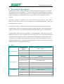
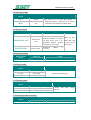
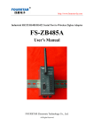
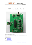
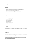
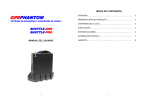
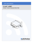
USER MANUAL
—CE-485Z/232Z WIRELESS MODULE
Shenzhen Sensor Electronic Technology Co., Ltd
www.ce-transducer.com
CE-485Z/232Z wireless module
1. Performance description
CE-48Z5/232Z wireless module is full zigbee wireless communication equipment,integrated
with zigbee RF transceiver and MCU,excellence with far distance communication, excellently
anti-jamming capacity. Enables point to point, one-to-multipoint, multi-to-multipoint between the
transparent transmission of data between devices; may form a star, tree and mesh network
structure.
The zigbee network is constituted of the center node and access node, the center node is
PAN_Coord, the access node is router or end device. you should install the PAN_Coord first,
then install the access node
CE-485Z/232Z wireless module can send the data by broadcasting, Except point to point data
communications, it also can communicate between the multi-point data, serial communication is
simple and convenient, it can greatly short modules embedded in the process of matching time
CE-485Z/232Z is made up of center coordinator, router and end node.. These three devices have
different net functions. Center coordinator is the center node of net. It is responsible for network
maintenance and management. Router is responsible for the data relaying and end node is only
responsible for TX and RX. These three kinds of devices go all the ways in hardware structure.
Just the embedded software is different, and different functions can be realized simply by jumper
settings or software configuration of the device.
2.
Spec.
Option
Wireless network
Data interface
RF MODEM
Performance
Communication
distance
CE-485Z/232Z parameter
Network topology
Star, line, mesh, tree
addressing
IEEE802.15.4/ZIGBEE standard address
Network ID
255
Max packet
256 bytes
Data interface
RS485、RS232
Serial ports signal
TXD, RXD, GND
Serial rate
1200 ~ 38400 bps(9600 bps default)
Parity type
None, Even, Odd(None default)
Data bit
7, 8(8 default)
Parity bit
1
modulation
DSSS (O-QPSK)
frequency
2.405GHz~ 2.480GHz
Wireless channel
16
RX sensitivity
-94 dbm
100m—2000m
2
CE-485Z/232Z wireless module
Power
consumption
RF power out r
-27dBm~25dBm
Antenna
SMA
Conflict prevention
CSMA-CA and CSMA-CA of GTS
Voltage input
DC 5V
max TX current
70 mA
max RX current
55 mA
Standby
10 mA
Saving
110 uA
Hibernate
30 uA
Working temperature
-40°C ~ 85°C
storage temperature
-55°C ~ 125°C
ENVIRONMENT
3.
Case Style and Connection
Fig. 3.1 Case style
Fig. 3.2 Installation
Fig. 3.3 CE-232Z
Fig. 3.4 CE-458Z
3
CE-485Z/232Z wireless module
4.
LED Indication
4.1 LED indication
LED
Run
Indication
Twinkle every
1s
Alarm
Data
Run OK
Not run, energy data power failure or
system failure
Connect net is OK
Not connect net
Run OK
System error or special mode
Send or receive the data for one time
Off
Network
Diagram
Description
ON
OFF
OFF
ON
ON/OFF
4.2 Pull-switch setting
(It is effective when the switch is closed, ON stands for closing, the diagram stands for
disconnecting.)
Switch
State
NO.
1
ON
2
3
4
ON
ON
ON
3、4
OFF
3、4
ON at the
same time
5.
Diagram
Function
System reposition, Level-triggered,
closed effective
Enter system config. mode
Type of module access node:end node
Type of module access node:center node
Type of module access node : break
router node off
Forbidden, please select only one
Module configuration parameters:
5.1 Initialization setting
1. Open the computer’s super end. The setting should be: baud rate 38400, data bit: 8,
checkout none, stop bit 1
2. Pull NO.2 switch to ON(closed,refer to table 4.2)
;
3. Power on, enter the system config mode;Select 1-Chinese, 2-English on super end.,.
Enter the menu, and then refer to 5.2-5.13.
5.2 MAC_ADDR CONFIG
MAC_ADDR
Add
Config
Remark
MAC_ADDR
(H)0000-FFFE
PAN_Coord is 0000
Must exclusive in same net。
Every CE-485Z has uniquesign of addr.. Same node cannot exist in one network. The addr. is 2
byte hex.
4
CE-485Z/232Z wireless module
5.3 Node type setting
NODE_TYPE
Option
PAN_Coord
Type
Center node
ROUTER
Router
Config
Remark
Include the function of
end code
Center node must
exist in net
END_DEVICE
End node
CE-485Z has 3 types: center node, router, end node. When select jumper settings through
software config, the node type will be selected by the NO.1 and NO.2 bit of pull-switch.
5.4 Setting of net type
NET_TYPE
Option
MESH
STAR
LINE_1
LINE_2
LINE_3
LINE_4
Net type
Mesh
Star
line ID=1
Line ID=2
Line ID=3
Line ID=4
PEER
Peer
Config
Remark
Master and slave net.
Center node must
exclusive in same net.
Net type must
exclusive in same
net。
No master and slave net
and no center node
5.5 Setting of network ID
NODE_TYPE
ID
Config
Remark
NET_ID
00-FE
Keep the ID unified in the
same net。
5.6 Channel config.
CHANNEL
Option
Config.
0-F
0 : 2.405GHz
1 : 2.410GHz
2 : 2.415GHz
3 : 2.420GHz
4 : 2.425GHz
5 : 2.430GHz
6 : 2.435GHz
7 : 2.440GHz
8 : 2.445GHz
9 : 2.450GHz
A : 2.455GHz
B : 2.460GHz
C : 2.465GHz
D : 2.470GHz
E : 2.475GHz
F : 2.480GHz
G
AUTO,select the best channel automatically
Remark
In the same one
system, the channels
of all modules must
be in the same
setting. Channel 9, E
and F channel are
recommended. They
can avoid WIFI.。
5
CE-485Z/232Z wireless module
5.7 Data type setting
DATA_TYPE
Option
Data type
Config.
ASCII
ASCII
HEX
Hex
Just need to be set with data sending to
destination address. And there is no need to
send when in broadcasting sending mode.
5.8 TX type setting
TX_TYPE Option
BROADCAST
Mode
Config.
Remark
Broadcast
No destination address
MASTER-SLAVE
Master and
slave
For the center node, a
destination address is needed.
For other nodes, there is no
destination address. Default
sends data to center node.
POINT-POINT
Point to point
destination
necessary
address
Addr. is 2 byte
MAC addr., add
it in the front of
data packet.
is
5.9 Baud rate setting
BAUD_RATE
Option
Baud rate
Config.
1200-115200
1200-115200
Select the matching baud rate
DATA_PARITY
Option
Type
Config.
NONE
EVEN
ODD
No parity
5.10 Parity setting
Even parity
Select the matching type
Odd parity
5.11 Data bit setting
DATA_TYPE
Option
Data type setting
Config.
7+1+1
8+0+1
8+1+1
Data 7 bit +parity 1 bit + stop 1 bit
Data 8 bit+ parity 1 bit +stop 1 bit
Data 8 bit +parity 1 bit +stop 1bit
Combine with parity setting
selection.
5.12 Serial ports time out setting
TIME_OUT
Option
Config.
Remark
TIME_OUT
1-255ms(hex display)
Serial ports time out
6
CE-485Z/232Z wireless module
5.13 Address of data source setting
SRC_ADR Option
Add. of data source
NOT OUTPUT
HEX
ASCII
No add. output
Config.
The origin adds. of data package
Hex output
ASCII output
Format of HEX output addr.:2 byte source addr. + effective data;
Format of ASCII output addr.: 4 byte source addr. + effective data;
6.
TX Type Config
6.1 TX Mode
Type
TX Mode
Broadcast
Center node
Non-center
node
Option
All non-center nodes in
the net
Remark
Send the data directly
Master and
slave or point to
point
Nodes with destination
address
Destination address + data
Broadcast
All non-center nodes in
the net
Send the data directly
Master and
slave
Center node
Send the data directly
Point to point
Nodes with destination
address.
Destination address + data
6.2 Frame format of data sending
TX Mode
Data code
Format of data frame
No change
Send the data
directly
Destination
address + data
Hex destination
address
ASCII destination
address + data
2 byte destination address + data
4 byte destination address + data
7、Notice:
1.
Please do not install this product outdoors or wet environments.
2. Please do not install this product in metal enclosure
3. Please install it in clear environments without blocking.
4. Please do anti-light protection if necessary.
7