1
USFM 100 Installation Guide, cont'd
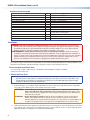
Hardware Included in the Kit
Parts
Qty
¼ - 20 x 2 inch, pan head bolts
¼ inch toggle assembly
¼ inch metal washers (47/64 inch O.D.)
5/16 x 3 inch lag screws
5/16 inch metal washers (11/32 inch I.D., 11/16 inch O.D.)
¼-28 x 3/4 inch screw
¼-20 x 1/2 inch button screws
10-32 x 3/8 inch pan head screws
10-32 x ¼ inch set screw
6-32 x ¼ inch button screws
4
4
8
4
4
1
4
2
1
12
6-32 x ½ inch button screws
Tie wraps
4-40 x ¼ inch pan head screws
4
4
4
Application
Base plate to wall installation
Base plate to wall installation
Base plate to wall installation
Base plate to wall installation
Base plate to wall installation and boom arm
Securing boom arm (top)
Securing boom arm (extension)
Securing boom arm (bottom)
Securing projector pipe
Securing covers for boom arm (10)
Securing device mounting plates
Securing plastic covers for enclosure
Securing power supply wires
Securing switcher to plate
Installation
WARNING: Risk of Personal Injury and Property Damage. Before commencing installation, the wall structure
must be examined to determine if it is suitable for the proper installation and support of this product. If needed,
the installer should reinforce the wall. Drywalls should have a minimum thickness of 1/2 inch and a maximum
thickness of 5/8 inch. Improper installation of this product could lead to serious injury.
AVERTISSEMENT : Risque potentiel de blessure grave ou de dommages matériels. Avant de commencer
l'installation, la structure du mur doit être examinée afin de déterminer si elle est appropriée pour l'installation et
la prise en charge correctes de ce produit. Si nécessaire, l'installateur devra renforcer le mur. Les murs en plaque
de plâtre doivent avoir une épaisseur minimum de 2,54 cm (1/2 inch) et une épaisseur maximum de 12,7 cm
(5/8 inch). Une installation non-conforme de ce produit peut engendrer des blessures graves.
The location and type of wall where the USFM 100 is to be installed should be identified before starting installation. This
determines the installation method and the type of fasteners used to secure the plate to the wall.
Recommended Installation Tools
• Level (24 inch) • Ladder • Tape measure • Stud finder • Drill and drill bits • Phillips screwdriver
• Allen hex wrench (5/64 size)
1. Mount the Base Plate
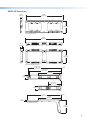
NOTE: Before installation, see the user manual for the display device to determine the proper location and
placement of the mount. Take into consideration the projector lens offset, screen size, screen aspect, and
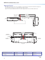
projected image throw distance. See page 8 for the dimensions of the USFM 100 (with the projector pipe
and UPB 25 attached) to aid in this determination
a.
At the desired site, use an edge-to-edge stud finder to locate the center of the wall studs (wood or steel). Mark
each stud location. Minimum joist size should be 2 inches by 4 inches.
ATTENTION: Potential Damage to Property. For secure installation, it is required to attach the base
ATTENTION :
b.
2
plate to two wall studs, using a minimum of four securing points. Drywall toggles can be
used for holes that are not aligned with studs (see figure 3). This product is not intended to be
mounted solely to drywall.
Risque de dommages matériels : Afin de sécuriser l’installation, il est nécessaire de fixer
la base a deux poteaux muraux en utilisant au moins 4 points de fixation. Des chevilles à
bascules adaptées à la cloison peuvent être utilisées si les percements ne sont pas alignés sur
le support. Ce produit n’est pas conçu pour être monté directement sur une cloison sèche.
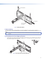
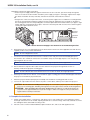
Hold and level the base plate against the wall. Mark a minimum of four positions (two top, two bottom) using either
the mounting slots or the keyholes (slots uppermost) that are on the stud lines (see the + marks in figure 2). Where
applicable, mark the mounting holes on the wall for drywall toggles.