1
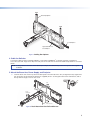
USFM 100
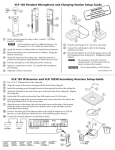
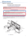
Base Plate
Cutout for
Signal Cable
Access
Level
Marker for
Pilot Hole
Mounting
Holes
Signal Cables
Exiting from
Cutout
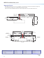
Figure 2. Wall
Mounting Features
c.
If the cables are to be run behind the wall to the USFM 100 location, mark the cutout area on the wall large enough
for signal cables (see inset in figure 2).
d.
Remove the base plate and set it aside. Cut out the marked area for cable access.
For drywall with wood studs
i. Drill ¼ inch (6.35 mm) pilot holes at the marked stud locations.
ii. Align the base plate mounting holes over the pilot holes and lightly secure with 5/16 inch lag screws and washers.
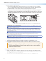
NOTE: If using toggle screws for assembly, follow the installation method (steps A-D) shown in figure 3.
A. Grasp plastic handle, collapse
toggle and insert into wall.
B. Slide plastic washer down
into pilot hole.
Figure 3. Steps
C. Cut off plastic handle close
to wall.
D. Hand screw in pan head bolt
until 1/8 inch gap remains.
for Toggle Assembly Installation
iii. Verify level and position, and fully tighten down all the screws to secure the plate flush to the wall.
For drywall with steel studs
i. Drill a ½ inch (13 mm) hole through the stud at each of the locations (four recommended).
ii. Insert the supplied toggles through the studs and lightly secure the plate using the four supplied
(¼-20 x 2 inch) bolts and washers.
iii. Verify level and position, and fully tighten down all the bolts to secure the plate flush to the wall.
3