1
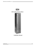
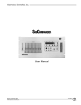
Mark VII Dimmer Bank
EDI
Mark VII Dimmer Bank
Users Manual
Revision 3, March, 1998
070-0510
©1998, Electronics Diversified, Inc.
1
Mark VII Dimmer Bank
Introduction
Description
This User's Manual is supplied with your Mark VII Dimmer Bank.
Copies of this manual may be obtained from Electronics
Diversified, Inc., for a nominal charge. It is recommended that
you copy those portions of this manual applicable to your present
use in the installation, maintenance or repair and preserve the
original in a safe place. Copyright 1996, by Electronics diversified,
Inc. All rights reserved.
The Mark VII Dimmer Bank uses Mark VII SCRimmer plug-in
dimmers mounted in a 24" rack enclosure.
SPI plug-in dimmers contain the active circuit components and
filter choke for each dimmer. Input power, load and control wiring
is supplied by the Mark VII bank. Each dimmer module is
individually cooled, as air is forced through the SPI from the Mark
VII system.
A wide variety of options and special features are available in the
Mark VII rack system:
No part of this Manual may be reproduced by any means,
graphic, electronic, or mechanical, including photocopying,
recording, taping, or information storage and retrieval systems,
without the express written permission of Electronics Diversified,
Inc., except in connection with installation, repair and maintenance
of installed Mark VII Dimmer Banks.
Introduction . . . . . . . . . . . . . . . . . . . . . . . . . . . . . . . . . . . . . .
.2
●
●
●
●
●
●
●
●
●
●
Description . . . . . . . . . . . . . . . . . . . . . . . . . . . . . . . . . . . . . . .
.2
All connections are available on the front of the rack. Mark VII
rack systems are U.L. Listed.
Table of Contents
Isometric Diagram . . . . . . . . . . . . . . . . . . . . . . . . . . . . . . . . .
3
Mounting . . . . . . . . . . . . . . . . . . . . . . . . . . . . . . . . . . . . . . . . .
.4
Floor Access . . . . . . . . . . . . . . . . . . . . . . . . . . . . . . . . . . .
4
Wiring Information . . . . . . . . . . . . . . . . . . . . . . . . . . . . . . 4
Line Connections . . . . . . . . . . . . . . . . . . . . . . . . . . . . . . .
4
Load Connections . . . . . . . . . . . . . . . . . . . . . . . . . . . . . . 4
Control Lines . . . . . . . . . . . . . . . . . . . . . . . . . . . . . . . . . . .
5
Single Dimmer Connection . . . . . . . . . . . . . . . . . . . . . . . 5
Main Power Connection . . . . . . . . . . . . . . . . . . . . . . . . . .
5
Field Wiring Connector Marking . . . . . . . . . . . . . . . . . . . 6
Cable Securement . . . . . . . . . . . . . . . . . . . . . . . . . . . . . .
6
Testing Connections . . . . . . . . . . . . . . . . . . . . . . . . . . . . 6
Control Connections . . . . . . . . . . . . . . . . . . . . . . . . . . . . 6
Three-pole main circuit breakers
100,000 AIC rated input bus bars
Houselight load circuit breakers
A slider cross-hatch panel
Panel lights with dimmer
Non-dim contactors
Constant circuits
Convenience outlet
Control cable connectors
Take-control circuitry (panic contactors)
WARNING:
Before working in, on, or about the Mark VII rack, TURN
OFF, LOCK AND TAG all disconnect devices that are
supplying, or will supply power to the dimming system.
Installation
An isometric view of a typical Mark VII dimmer rack is
shown on page 3. Before installing, carefully study the
specific shop drawings for this particular piece of equipment.
Particular attention should be given to the Riser Diagram,
Field Wiring Diagram, and the general details of each
component comprising the dimmer system, before
installation begins.
Mullti-Link Control Unit . . . . . . . . . . . . . . . . . . . . . . . . . . . . .
.7
60-Channel Board Programming . . . . . . . . . . . . . . . . . . .
7
Calibration . . . . . . . . . . . . . . . . . . . . . . . . . . . . . . .
......7
Analog Backup Operation (optional) . . . . . . . . . . . . . . . . 7
NOTE:
Troubleshooting Guide . . . . . . . . . . . . . . . . . . . . . . . . . . . . .
.8
WARNING:
Unobstructed air supply to the rack is essential for ventilation
cooling. Air is drawn through the bottom front vents and
exhausted from the upper front vents. Do not attempt to
install the Mark VII in a location without adequate ventilation.
The Mark VII rack is designed to operate over a temperature
range of 0 - 104°F (-18 - 40°C.)
Maintenance
. . . . . .operation
. . . . . . and
. . . storage
. . . . . .environment
. . . . . . . . . for
. . this
......
Maximum ambient
8 equipment is 104°F (40°C), with 90% humidity, non-condensing. Extreme caution is advised when having liquids, food and
Replacement
Parts any
. . . .equipment.
. . . . . . . . .During
. . . . . severe
. . . . . .electrical
........9
cigarettes around
storms,
Service
. . equipment
. . . . . . . .should
. . . . be
. . disconnected.
. . . . . . . . . . Failure
. . . . .to. .adhere
. . . . .to. . . .
. 9 these requirements may result in malfunction or serious damage.
Registration . . . . . . . . . . . . . . . . . . . . . . . . . . . . . . . . . . . . . .
. 10
2
Mark VII Dimmer Bank
Mark VII Dimmer Bank Isometric Diagram
ALL LOADS FEED
THROUGH TOP
CONTROL WIRES IN CHASE
MODULAR SHELVES
WELDED STEEL FRAME
DIMMER MODULE
POWER FEEDS TO
DIMMER MODULES
CONTROL MODULE
FAN
NEUTRAL BUS
POWER BUSSES
(RACK FEEDS FROM
BOTTOM OR SIDE)
NOTE: Drawing not to scale
3
Mark VII Dimmer Bank
Mounting
To gain access to the floor mounting holes, remove the air filter
assembly held in place by four screws. The side panels may also
be removed by taking out the red hex-head bolts, one on the side
of each panel. Side panels will lift up and out easily.
If additional access is desired, the hinged convenience panel
may be released.
Wiring:
For easiest access during wiring, dimmer
support trays should be removed. Trays are
held in position by two screws, one on each
side. Trays pull out forward.
Mark VII Dimmer Tray Removal
TOP PANEL
Floor Mounting
Access:
REMOVE TWO SCREWS
IN EACH TRAY
THEN PULL TRAY
STRAIGHT OUT
HINGE
TO INSTALL TRAYS
REVERSE THE ABOVE
CONTROL MODULE
CONVENIENCE PANEL:
REMOVE TWO SCREWS,
SWING OUT PANEL
Line
Connections:
REMOVE FOUR SCREWS
SET AIR FILTER ASIDE
MARK VII FRONT VIEW
Mount the Mark VII in position using bolts
through the mounting holes inside the base of
the rack.
On a system with a main circuit breaker, line
connections are made to the breaker terminals.
Other systems have direct feed connections
to the bus bars
The main neutral is connected to the neutral
terminal bus. The main ground is connected
to the ground terminal.
Neutral Bus Location
FAN
WIRING
ACCESS
AREA
FLOOR
MOUNTING AREA
(4)
REAR
CONTROL
CONNECTION
AREA
BUS BARS
NEUTRAL BUS BAR
GROUND TERMINAL
MARK VII BOTTOM VIEW
Wiring
Mark VII Dimmer Bank rack systems are wired for 3-phase, 4wire, 120/208 Volt, 50/60Hz or Single-phase, 3-wire, 120/240
Volt, 50/60Hz power. Maximum current draw per phase leg is
shown on the label next to the power terminals.
Refer to the specific shop drawings for contractor load area and
recommended load entry area. Load neutrals coming into the
dimmer bank should be long enough to reach the neutral bus bar
when neatly routed and dressed from either side of the dimmer
support trays.
The top panel sections are held by four screws in each section.
The rear panel is commonly prepared to accept the chosen wire
routing devices for load wiring. (Refer to Isometric Drawing, page
3).
Load
Connections:
4
Load connections are made at the Mark VII
plug-in block terminals for each SPI dimmer.
Non-dim connections are made at the terminal
strips. For SPI 6.0Kw or 7.2Kw units, load
connections are normally made at the branch
breakers.
Load line and neutral connections to the
dimmer bank are done with ¼-20 hex socketset screws that require a .125 (1/8") hex Allen
wrench. The dimmer bank is shipped with
these screws in place, and backing out is
necessary before connections can be made.
Mark VII Dimmer Bank
Load
Connections:
Single Dimmer
Connection:
Connecting a load to a specific dimmer requires
determining where that dimmer is located in
the bank. Dimmer numbering begins in the
upper left-hand corner of the rack, going from
left to right on each dimmer tray.
Each dimmer tray holds up to six modules.
Each module may contain one, two or four
dimmers, respectively. Refer to the shop
drawings to determine which type of dimmer
modules will be installed in the rack.
SPI 2 x 6
SPI 1 x 12
SPI 2 x 2
The load line screws are accessed by inserting
the hex Allen wrench into the appropriate hole
at the front of the dimmer load connection
block.
Typical Load Connections
Example: Your installation calls for a dimmer
bank that will be filled with SPI 2 x 6 modules,
and a particular load must be assigned to
dimmer 28. Examination of the Shelf Wiring
Diagrams in the shop drawings shows that
dimmer 28 will be located on the third shelf
down, second load connection block from the
left, right hand pin hole in that block.
Constant circuit loads are wired to front panel
circuit breakers, which are provided for the
control units and for the cooling fans.
If the system has a patch panel, load
connections are made at the patch panel's
load circuit breakers.
Cut the load neutral wires to length and remove
11
/32" of insulation from each. Insert wire in
neutral bus hole and tighten screw to 4 ft.-lbs.
Cut the load wires to length, removing 1/2" of
the insulation, and insert them into their
appropriate holes. Tighten to 4 ft.-lbs.
Control Lines:
WARNING:
Before working in, on, or about the Mark VII
rack, TURN OFF, LOCK AND TAG all
disconnect devices that are supplying, or will
supply power to the dimming system.
Main Power
Connection:
The Mark VII Dimmer Bank modules may be
controlled by either multiplex and/or analog
formats. Typical control connections include
USITT DMX-512, AMX-192, RS422, and 0+10V analog backup output controller.
Consult the control connection diagram in the
shop drawings for specific details.
Control Connections
The main feed connection point is in the bottom
of the rack. If entry will be from the side, the
side panel must first be re-installed.
Attachment of the main feed cables to a rack
equipped with a Main Feed Bus Bar system is
via contractor-supplied lugs and bolts, sized
to the main feed cable, bolted in the middle of
the bussing system.
Main Feed Connectors
MULTI-LINK CONNECTOR:
5-PIN XLR TYPE
WIRING CONNECTIONS:
5
1.
2.
3.
4.
5.
4
3
2
1
PHASE BLOCKS
Control Ground
Multiplex Multiplex +
Analog Multiplex
Overtemp
A
ANALOG BACKUP CONNECTOR: 15-PIN D TYPE
1
C
8
PIN #
9
15 GROUND
CABLE FEED
CAN BE BOTTOM
OR SIDE
B
1
2
3
4
5
6
7
8
9
10
11
12
13
14
15
WIRE #
SIGNAL
DESIGNATION
1
SUB 01
2
SUB 02
3
SUB 03
4
SUB 04
5
SUB 05
6
SUB 06
7
SUB 07
8
SUB 08
9
SUB 09
10
SUB 10
----------------15 CONTROL GROUND
FRONT
Insert the cable into the proper holes on the
feed block and secure them in place
U.L. AIC rating for the Mark VII may be up to
100,000 Amperes short circuit. This rating is
permitted only if feed wires are properly
secured.
5
Mark VII Dimmer Bank
Field Wiring
Connector
Marking:
reading should be ZERO, or very close to zero
if they are connected together at the power
source (normal practice).
Connect feeders with one of these pressure
terminal types.
Wire
Size
P/N
Color
Pink
Die
B. With all circuit breakers turned off, verify
that no dead shorts (zero ohms) exist between
any of the phases.
Manufacturer
1/0
AWG
R1038
2/0
AWG
CRB-2/0 Black
5
Hollingsworth
6
Ilsco
3/0
AWG
R3038
3/0
AWG
Orange
9
Hollingsworth
CRA-3/0 Orange
9
Ilsco
4/0
AWG
54112
Purple
54
Thomas & Betts
4/0
AWG
CRA-4/0 Purple
10
Ilsco
250
MCM
R25038
Yellow
-- Hollingsworth
250
MCM
54174
Yellow
62
Thomas & Betts
White
66
Thomas & Betts
300
MCM
54179
600
MCM
62223A
--
-- Thomas & Betts
700
MCM
62223A
--
-- Thomas & Betts
800
MCM
TA-8005
--
-- Ilsco
900
MCM
326503
--
1000
MCM
YA44-L
White
C. Should any of the readings be other than
above, make necessary corrections, re-check
and verify before applying power.
Control
Connections:
-- AMP
27
AMP
CAUTION:
Check tool manufacturer's exact instructions for
the number of crimps required for selected
terminal
Cable
Securement:
Wrap line cable together with nominal 3/8"
(9.5mm) nylon rope having a minimum tensile
strength of 2000 lbs. @:
1). 6" (152mm), and @ 12" (305mm) from the
line terminals with five wraps, and
2). Five wraps every additional 6", or one wrap
every 1" (25.4mm).
NOTE: After each of the remaining steps, check
all components that make up the dimming system
for abnormal indications, such as smoke, or the
smell of burned or burning components.
NYLON ROPE-MINIMUM OF FIVE WRAPS
A. Apply power to the dimmer bank by turning
on the dimmer bank's main disconnect
service.
B. Turn ON the "A" breaker on the
convenience panel and note that the "A"
pilot light on the Control Interface Module is
illuminated. Turn off the breaker
immediately if there is any abnormal
indication. Investigate and correct any
malfunctions before proceeding.
C. Turn ON the phase "B" breaker, noticing
that the "B" pilot light illuminates.
D. Turn ON the phase "C" breaker, noticing
that its pilot light illuminates.
E. Connect any portable control consoles,
ensuring they are switched to the OFF
position before being connected. Set up
the control console according to the
manufacturer's operation manual. Check
out the dimming system, one circuit at a
time, for proper operation.
6 INCHES
(152MM)
Testing
Connections:
Refer to the Mark VII diagram and field wiring
diagrams in the shop drawings for the control
connections. Access to the connection area
from the front of the rack is obtained by
removing the air filter assembly and opening
the convenience panel area. (See Floor
Mounting Access, Page 4).
Once all power and control connections have
been made and verified, and all installation
debris removed, re-install the dimmer support
trays, panels, and put the dimmer modules in
place.
If a Field Engineering turn-on is part of the
contract, DO NOT energize the dimmer bank.
If a Field Engineering turn-on has not been
provided as part of the contract, ensure that all
breakers in the dimmer bank are in the OFF
position, all portable plug-in controls are in the
OFF position, and all control sliders are in the
"0" or down position.
Before applying power, it is important to ensure
proper isolation between the power feed, neutral
and ground cable. To make the necessary
check, use an ohmmeter or a multimeter in the
ohms (resistance) position.
A. Use a low-resistance scale of the meter to
measure the continuity between "earth ground"
(chassis) and the dimming system neutral. The
6
Mark VII Dimmer Bank
Multi-Link Control Unit
The Multi-Link Control Unit is capable of accepting DMX-512.
AMX-192, RS422, and 0 - +10 VDC analog input as the control
signal. From the control signal input and the dimmer power input,
phase relationship outputs are provided to control up to 120
dimmers. The control unit consists of a power supply board, one
or two decoder boards, and an optional analog backup matrix
board. Each decoder board is capable of decoding 60 dimmer
channels.
The power supply board and its associated transformer generate
the necessary voltages for operation of the control unit, and
conditions the power input-phasing information for application to
the decoder board ramp-generator circuitry. The power supply
has no adjustments.
The decoder boards, one for up to 60 channels and two for up to
120 channels, accept the input control signal, along with phasing
information, and generates an output pulse for each dimmer. The
time at which these pulses occur must coincide with the respective
dimmer's power phase for proper dimming to occur. The decoder
boards have a ramp generator circuit for each phase. These
ramp circuits require level adjustments to compensate for
component aging, power input changes, lamp changes, etc.
There is also a four-circuit dip switch for changing the addressing
of each decoder board in multiples of 60. Refer to the chart below
for the various switch settings.
1= ON
60-Channel
Board
Programming:
The Multiplex Signal Format (FORMAT ADC)
Switch accommodates various control signal
input formats:
A = AMX-192 USITT Analog Multiplex format.
D = DMX-512 USITT Digital Multiplex format.
C = RS422 Digital Multiplex format.
Calibration:
Analog Backup Operation
The (optional) analog backup matrix board is used only in
controller units purchased with analog backup capability. It is
usually set up during system installation, using small jumpers in
the patch matrix to cause pre-determined lights to be controlled
by the analog back-up function, available in EDI control consoles.
There are no active components or adjustments on this board.
If your dimming system is supplied with an emergency analog
backup pin matrix and the CPU (internal software) fails in the
control console, you may turn a keyswitch that activates the
backup power supply. (Refer to the control console user's manual).
The power supply will cause the console's 10 submasters (or first
10 sliders) to output to a 0 - +10 VDC signal to the backup pin
matrix. Pin matrices are mounted on a circuit card in groups of 60
x 10 or 120 x 10. from one backup card, up to 120 dimmers can
be assigned to any of the 10 submasters. For systems with more
than 120 dimmers, multiple cards may be used.
0= OFF
CHANNELS
SWITCH SETTING
001-060
061-120
121-180
181-240
241-300
301-360
361-420
1110
0110
1010
0010
1100
0100
1000
Analog Matrix Detail
The following illustration shows a portion of the matrix as it is
factory preset. To set the sliders to the desired positions, insert
the dimmer pin in the channel position. Dimmers 1 through 10
are assigned to submaster 10.
DETAIL A
Detail "A"
1
2
4
6
8
NOTE: The control unit was calibrated at the factory,
and further adjustments should NOT BE
NECESSARY unless tampering or malfunction has
occurred and has been repaired.
10
3
5
7
9
7
Mark VII Dimmer Bank
Troubleshooting Guide
Symptom
Possible Cause
Remedy
Nothing works, green indicators
1, 2, and 3 are dark.
Control power switch is off.
Input power source is off.
Turn on control power switch.
Check input power source.
Nothing works, green indicator
1 is dark, 2 and 3 are on.
A dimmer channel is always ON.
Phase A (Line 1) fuse blown.
Phase A (Line 1) power source off.
Defective solid-state relay.
Replace fuse.
Check input power source.
Replace the solid-state relay.
A dimmer channel is always OFF.
The dimmer module is not plugged in.
The solid-state relay control connector
is loose, unplugged, or plugged in
backwards.
Defective solid-state relay.
Make sure dimmer is firmly plugged in all the way.
Check control wiring connector to solid state relays.
All of the lamps "ghost" (glow).
Lamp preheat set too high.
Dimmer out of calibration.
Rotate the preheat control counter-clockwise.
Contact the factory.
The multiplex signal indicator flashes,
lamps flicker, or dimmers refuse to
respond to multiplex signal.
Dimmer address set to 00.
Set the dimmer pack address to a valid number.
Bad multiplex cable.
Multiplex format set to wrong setting.
Check the dimmer pack with a known good cable.
Set the format switch to the proper format.
Lamps flash, flicker, or sequence.
Bad multiplex cable.
Multiplex format set to wrong setting.
Check the dimmer pack with a known good cable.
Set the format switch to the proper format.
The overtemp lamp is always on or
comes on when a dimmer channel
is brought up.
The dimmer module is not plugged in
Make sure dimmer is firmly plugged in all the way.
The dimmer pack overheats.
The cooling vents are blocked.
The dimmer pack is full of dust.
Clear any obstructions to the cooling vents.
Carefully remove dust and dirt with compressed
air or a vacuum cleaner.
Relocate the dimmer to a cooler location.
The dimmer is in a very warm location.
Lamps go out before the console
sliders reach zero.
Lamps are on full before console
sliders reach full.
Input power error light on.
The analog control console is not set
for 0 - +10V output.
The low-end calibration is out of
adjustment.
Replace the solid-state relay.
Check the output from the console.
Contact the factory.
The analog control console is not set
for 0 - +10V output.
The high-end calibration is out of
adjustment.
Check the output from the console.
Faulty or incorrect input power wiring.
Disconnect the power immediately!
Check for voltage between the ground and neutral
conductor. Check all input power wiring.
Contact the factory.
Maintenance
Disconnect Power First! About once a year (or more frequently,
if the Dimmer Bank is used often), remove the modules and
inspect the connector pins. Clean them with No. 400 or finer
sandpaper and carefully spread the pins SLIGHTLY with a
screwdriver.
Disconnect power from the rack before cleaning pins in the
housing. If the modules become clogged with air-born dirt, they
should be vacuumed. This will increase cooling efficiency and
prolong component life.
8
Mark VII Dimmer Bank
Replacement Parts
Replacement parts are available from Electronics Diversified,
Inc.
To obtain replacement parts, call (800) 547-2690 and ask for
Customer Service.
Since these systems are customized for individual applications,
it is important that you have the following information available
when you call.
The equipment type or number, serial number, and original EDI
system drawing number (As-Built Drawing Number). Please
SPECIFY LINE VOLTAGE.
When calling, the customer service representative will help to
determine the proper part you need, and any additional parts, if
necessary, depending upon your requirement.
EDI Part No.
Description
133-0003
260-2021
152-2025
392-1031
392-1032
342-1003
675-9142
670-9147
Duplex Receptacle
Circuit breaker (20 Amp)
SSR Dual (40 Amp)
Front Plate Connector Block
Back Plate Connector Block
Insulator, SPI Connector Block
60-Channel ML/ML w/Fixed Board
ML II Power Supply
Service
EDI offers a 24 hour Service / Support Network.
For technical questions about this product or operational assistance, ask for Customer Service at: . . . . . . . . .
1-800-547-2690
You may communicate by FAX: . . . . . . . . . . . . . . . . . . . . . . . . . . . . . . . . . . . . . . . . . . . . . . . . . . . . . . . . . . . . . . . . . . 1-503-629-9877
After Hours Emergency contact: . . . . . . . . . . . . . . . . . . . . . . . . . . . . . . . . . . . . . . . . . . . . . . . . . . . . . . . . . . . . . . . . . . 1-503-645-5533
Ask for Emergency Assistance.
Internet: . . . . . . . . . . . . . . . . . . . . . . . . . . . . . . . . . . . . . . . . . . . . . . . . . . . . . . . . . . . . . . . . . . . . . . . . . . . . . . . . . . . . . www.edionline.com
Internet E-Mail: . . . . . . . . . . . . . . . . . . . . . . . . . . . . . . . . . . . . . . . . . . . . . . . . . . . . . . . . . . . . . . . . . . . . . . . . . . . . . . . . . [email protected]
If your Mark VII Dimmer Bank needs repair, call 503-645-5533 for a Return Materials Authorization number, and a shippping address
will be furnished
This is a product of:
1675 N.W. Cornelius Pass Road, Hillsboro, Oregon 97124 USA
9
Mark VII Dimmer Bank
Attention Mark VII Dimmer Bank owners!
Please return this registration card immediately.
Your prompt attention to this matter will ensure your receiving updated technical
information for this product as it becomes available. Please complete all information.
Look for acknowledgment of your registration within 6-8 weeks.
Name: _______________________________________________________
Title: ________________________________________________________
Facility and/or Company: ________________________________________
_____________________________________________________________
Street Address: _______________________________________________
_____________________________________________________________
City: ____________________________ State: ______ Zip: __________
Phone: ______________________________________________________
E-mail: ______________________________________________________
Web site: ____________________________________________________
Mail to:
EDI User Manual Registration
1675 NW Cornelius Pass Road
Hillsboro, Oregon 97124
!
CUT ALONG DOTTED LINE
Fax: _________________________________________________________
or FAX to: (503) 629-9877
Revision 2, May 1998
10