1
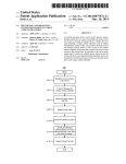
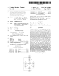
US 20120313750A1
(19) United States
(12) Patent Application Publication (10) Pub. No.: US 2012/0313750 A1
(43) Pub. Date:
AU et al.
(54)
SECURITY SYSTEM, MODULES AND
(52)
Dec. 13, 2012
US. Cl. ..................................................... .. 340/5.61
METHOD OF OPERATION THEREOF
(76) Inventors:
Jonson Chung-shun AU, Fremont,
CA (U S); Melvin Sik Yu LI,
(57)
Fremont, CA (US)
(21) App1.No.:
13/540,629
(22) Filed:
Jul. 3, 2012
ABSTRACT
The present invention is concerned With a security system.
The system may comprise at least a ?rst handheld device, a
second handheld device, a ?rst secure entity, and a second
secure entity. The ?rst handheld device and the ?rst secure
entity are electronically pre-registered With each other, the
?rst handheld device and the second secure entity are elec
Related US. Application Data
tronically pre-registered With each other, the second handheld
(63) Continuation-in-part of application No. 12/367,554,
(51)
?led on Feb. 9, 2009.
device and the ?rst secure entity are electronically pre-regis
tered With each other, and the second handheld device and the
second secure entity are electronically pre-registered With
Publication Classi?cation
Int, Cl,
G05B 19/00
(200601)
each other, With pre-registration of each respective handheld
device and secure entity pair establishing a unique channel for
the respective handheld device and secure entity pair.
Security Entity S1
Security Entity S2
Input
Actuated
Input
Actuated
sensor
output
sensor
output
device(s) device(s)
device(s) device(s)
Base Unit
B1
Base Unit
B2
K
\\\\
/
\\\
/
\
.\
// /
Handheld
Device
H1
1 ‘k
\\\\\
\\\\
\
I
Dashed Llnes as
Wireless Signals
Handheld
Device
H2
Patent Application Publication
Dec. 13, 2012 Sheet 1 of9
US 2012/0313750 A1
Security Entity S2
Security Entity S1
Input
Actuated
Input
Actuated
sensor
output
sensor
output
device(s) device(s)
device(s) device(s)
Base Unit
B1
Base Unit
B2
v
4
/
/
/
/
/
Handheld
Device
Figure 1
Dashed Lines as
Wireless Signals
Patent Application Publication
Dec. 13, 2012 Sheet 2 0f 9
Security Entity 81
US 2012/0313750 A1
Security Entity 82
Input
Actuated
Input
Actuated
sensor
output
sensor
output
device(s) device(s)
device(s) device(s)
Base Unit
B1
Base Unit
B2
\
1 ‘g
/
, //
l’
Handheld
Device
H1
Figure 2
Dashed Lines as
Wireless Signals
Handheld
Device
H2
Patent Application Publication
Dec. 13, 2012 Sheet 3 0f 9
Security Entity S1
Security Entity S2
Input
Actuated
Input
Actuated
sensor
output
sensor
output
device(s) device(s)
device(s) device(s)
Base Unit
B1
Base Unit
B2
:4‘ ‘ v
|§
I
US 2012/0313750 A1
aw
“Q4121 $2.19?”
| :
| :
| l
s1.2\§\ ////H1.2
/
//>\\
/
\ \\\
Handheld
Device
H1
IQ
2 2: lm . 2
Dashed Lines as
Wireless Signals
S -
Handheld
Device
H2
An example of wireless signal content: Signal H1.1 contains
<H1> as handheld’s Identification Code and
<1> as handheld's Channel Code
Figure 3
Patent Application Publication
Dec. 13, 2012 Sheet 4 0f 9
US 2012/0313750 A1
Signal sent from H1, intended to S1 (H1.1)
OOO1_1011_1000_OOO1
Identification of H1
0_0001
OOOO_OOOO_O100_1000
Channel Code
Instruction data from
assigned to
H1 for door locking
S1 in H1
in S1
Responding Signal sent from S1, intended to H1 ($1.1)
1o00_0010_0001_0000
0_0001
Identification of S1
Channel code
assigned to
H1 in 81
Figure 4
00o0_o001_1101_0010
Instruction data from 81
for turning on the lock
icon in H1
Patent Application Publication
Dec. 13, 2012 Sheet 5 0f 9
US 2012/0313750 A1
Signal sent from H1, intended to S2 (H1.2)
OOO1_101 1_1000_OOO1
Identification of H1
O_OO1O
OOOO_OOOO_O100_1000
Channel Code
Instruction data from
assigned to
H1 for door locking
S2 in H1
in $2
Responding Signal sent from S2, intended to H1 ($2.1)
1000_OO1 1_OO10_O1OO
O_OOO1
Identification of S2
Channel code
assigned to
H1 in S2
Figure 5
OOOO_OOO1_1 1 O1_OO1O
Instruction data from 82
for turning on the lock
icon in H1
Patent Application Publication
Dec. 13, 2012 Sheet 6 0f 9
US 2012/0313750 A1
Signal sent from H2, intended to S2 (H2.2)
0101_1000_0000_1101
Identification of H2
0_0010
00o0_0000_0100_1000
Channel Code
Instruction data from
assigned to
Hg for door locking
S2 in H2
in S2
Responding Signal sent from S2, intended to H2 ($2.2)
1000_OO11_OO10_O1OO
O_OO1O
Identification of S2
Channel code
assigned to
H2 in 82
Figure 6
O00O_OOO1_1101_OO1O
Instruction data from 82
for turning on the lock
icon in H2
Patent Application Publication
Dec. 13, 2012 Sheet 7 0f 9
US 2012/0313750 A1
Patent Application Publication
Dec. 13, 2012 Sheet 9 0f 9
US 2012/0313750 Al
F
Display
Handheld Unit
Figure 9
Dec. 13, 2012
US 2012/0313750 A1
SECURITY SYSTEM, MODULES AND
device of the respective handheld device and secure entity
METHOD OF OPERATION THEREOF
pair, d) each of the ?rst signal and the second signal contains
RELATED APPLICATION
the ?rst part coding of the ?rst signal represents an identi?
cation of said handheld device of the respective handheld
device and secure entity pair, the second part coding of the
?rst signal represents a channel code designated in said hand
held device With respect to said secure entity of the respective
handheld device and secure entity pair, and the third part
coding of the ?rst signal represents an instruction from said
handheld device to said secure entity of the respective hand
held device and secure entity pair. Preferably, the ?rst part
coding of the second signal may represent an identi?cation of
coding of at least a ?rst part, a second part and a third part, e)
[0001]
The present invention is a continuation-in-part
application from US. patent application Ser. No. 12/367,554
?led Feb. 9, 2009, content of Which is incorporated herein in
its entirety.
FIELD OF THE PRESENT INVENTION
[0002]
The present invention is concerned With a security
system for controlling access to one or more secure entities by
one or more users. The present invention is also concerned
With, but not limited to, modules of such security system, a
method of providing such security system, a method of oper
ating or implementing such security system and a platform of
the secure entity of the respective handheld device and secure
entity pair, the second part coding of the second signal may
represent a channel code designated in the secure entity With
respect to the handheld device of the respective handheld
allowing different modules being compatible With each other
in such security system.
device and secure entity pair, and the third part coding of the
BACKGROUND OF THE PRESENT INVENTION
entity to the handheld device of the respective handheld
device and secure entity pair. With such con?guration, only
signals from the respective handheld device intended for the
[0003] Mechanical locks and keys have been used for thou
sands of years for controlling access to premises. NoWadays,
it is still typical that a user Wouldrequire tWo mechanical keys
to gain access to his/her residence. One of the mechanical
keys may be for the knob-type lock on the main door to the
second signal may represent an instruction from the secure
respective secure entity Will be responded by the respective
secure entity and only signals from the respective secure
entity generated in response to the signals from the respective
handheld device Will be responded by the respective handheld
bolt lock for added security. Then the user may have a further
mechanical key for his/her primary car and a further elec
device.
[0006] Preferably, the handheld devices may be remote
control key fobs or cellular phones, and the secure entities
tronic remote alarm device for the car. If the user has a second
car or has access to the spouse’s car, s/he may have tWo more
may be vehicles, premises or computers.
[0007] In an embodiment, the said handheld devices may
electronic handheld devices to carry With the key chain. In
include means for a user to input command for emitting the
Wireless signal. The input means may be one or more physical
and/or virtual touch-screen keys or buttons.
residence and the other mechanical key may be for the dead
addition, s/he may have one or tWo more mechanical or elec
tronic keys or card keys for access to his/her Work place. As
can be realiZed, the user can easily be carrying about ten keys
of different types. This is very cumbersome.
[0004] The present invention seeks to provide a solution to
the above described problem, or at least to provide an alter
native to the general public.
SUMMARY OF THE INVENTION
[0008]
[0009]
[0010]
[0011]
[0012]
handheld device, a second handheld device, a ?rst secure
[0013]
entity are electronically pre-registered With each other, and
the second handheld device and the second secure entity are
electronically pre-registered With each other, With pre-regis
tration of each respective handheld device and secure entity
pair establishing a unique channel for the respective handheld
device and secure entity pair, b) each said unique channel is
con?gured to alloW tWo-Way communication by encoded
Wireless signals betWeen the respective handheld device and
secure entity pair, c) the encoded signals include a ?rst signal
emitted from the handheld device intended for the secure
entity of the respective handheld device and secure entity pair,
and a second signal emitted from the secure entity intended
for the handheld device of the respective handheld device and
(i) locking or unlocking the ?rst secure entity,
(ii) arming or disarming the ?rst secure entity;
(ii) alloWing or disalloWing access to the ?rst
secure entity;
[0005] According to a ?rst aspect of the present invention,
there is provided a security system, comprising at least a ?rst
entity, and a second secure entity, Wherein a) the ?rst hand
held device and the ?rst secure entity are electronically pre
registered With each other, the ?rst handheld device and the
second secure entity are electronically pre-registered With
each other, the second handheld device and the ?rst secure
In one embodiment, the ?rst signal encoding the
instruction for a desired predetermined action may be
selected from a group including:
(iii) activating or deactivating the ?rst secure
entity; and
(iv) checking locked/unlocked status of the ?rst
secure entity.
[0014] Suitably, the handheld devices may include means
for displaying and/or indicating status of the secure entity in
the respective handheld device and secure entity pair.
[0015] In a speci?c embodiment, the encoded Wireless sig
nals may be of radio frequency.
[0016] In a useful embodiment, the security system may
comprise one or more handheld devices registrable With one
or more of the secure entities. Additionally or alternatively,
the security system may comprise one or more secure entities
registrable With one or more of the handheld devices. Such
feature(s) can leaving room for expansion When more hand
held devices and/ or more secure entities are acquired
[0017] Advantageously, at least one of the secure entities
may be con?gured to emit a third Wireless signal for indica
tion of an exception event When a predetermined status is
detected by the secure entity, and Wherein the third Wireless
signal is independent of the ?rst and second signals. The
secure entity pair, With the second signal generated only in
security system may be con?gured such that one of the hand
response to the ?rst signal and actionable by the handheld
held devices or at least one handheld device is respondable to
Dec. 13, 2012
US 2012/0313750 A1
the third Wireless signal, leading to a corresponding indica
ing pre-registered With the particular or target entity. Differ
tion on the handheld device(s).
ent embodiments of the invention are noW illustrated beloW.
Embodiment 1
BRIEF DESCRIPTION OF THE DRAWING
[0018] The present invention Will be explained by Ways of
non-limiting examples, With reference to the attached draW
ings, in Which:
[0019] FIG. 1 is a schematic diagram shoWing different
modules and their relationship in an embodiment of a security
system in accordance With the present invention;
[0020] FIG. 2 is a schematic diagram shoWing different
modules and their relationship in another embodiment of a
security system in accordance With the present invention;
[0021] FIG. 3 is a schematic diagram corresponding to FIG.
2 but With more information shoWing unique communication
links of the different modules;
[0022] FIG. 4 is a data content diagram shoWing the Work
ing of tWo unique communication links of a module pair of
FIG. 3;
[0023] FIG. 5 is a data content diagram shoWing the Work
ing of tWo unique communication links of one of the other
module pairs of FIG. 3;
[0024] FIG. 6 is a data content diagram shoWing the Work
ing of tWo unique communication links of yet one of the other
[0029] FIG. 1 illustrates, schematically, a ?rst embodiment
of a security system in accordance With the present invention.
The security system comprises a number of module types.
The module types include a ?rst module type or a handheld
device, eg H1. Handheld device H1 is relatively compact
and the appearance resembles a car remote control device that
is currently available on the market. In this embodiment,
handheld device H1 has a total of six button-type keys,
namely K1, K2, K3, K4, K5, K6, and one liquid crystal
display. Handheld device H1 is con?gured to emit up to six
different Wireless signals. Depending on Which of the keys is
depressed a corresponding signal is emitted. The security
system further comprises a second module type or a ?rst
secure entity. In this embodiment, the secure entity S1 is a
conventional vehicle except in the present invention it is
provided With a base unit B1 With Which handheld H1 can
communicate. In other Words, handheld device H1 serves as a
key for access to both vehicles S1, S2.
[0030]
In this embodiment, When vehicle S1 is ?rst pur
chased, it is purchased With handheld device H1. Speci?cally,
handheld device H1 and vehicle S1 are pre-registered With
each other before they can be put into use. Details of the
blocks of an embodiment of a security system in accordance
pre-registration Will be explained in further detail later in the
description. Once the pre-registration process has taken
place, handheld device H1, on depressing of key K1, emits a
?rst Wireless signal detectable by a receiver in base unit B1 of
the ?rst vehicle S1. The ?rst Wireless signal includes codes
encoding a ?rst instruction for locking all doors of vehicle S1.
The receiver of vehicle S1, on receiving the ?rst Wireless
signal, reacts by sending a corresponding signal to a micro
With the present invention; and
[0027] FIG. 9 is a schematic diagram shoWing the layout
processor in base unit B1, Which in turn sends a “lock” signal
to all the doors, in accordance With the ?rst instruction. On
module pairs of FIG. 3;
[0025] FIG. 7 is a schematic diagram shoWing different
modules and their relationship in yet another embodiment of
a security system in accordance With the present invention;
[0026] FIG. 8 is a schematic diagram shoWing functional
appearance of an embodiment of a handheld device in accor
completion of the locking of all the doors, a signal is gener
dance With the present invention.
ated by base unit B1 to a Wireless signal transmitter for
transmitting a second Wireless signal from vehicle S1 to hand
held H1 for con?rming the action of locking all the doors of
the vehicle S1. Handheld device H1, on receiving the second
Wireless signal from vehicle S1, Will display on the LCD
display the status of the doors of vehicle S1, i.e. the locked
status of the doors. With this, When the user desiring to check
Whether the doors have been locked, s/he can simply look to
the LCD display of handheld device H1 for the status of the
doors. This is to be contrasted With conventional systems in
DETAILED DESCRIPTION OF PREFERRED
EMBODIMENTS OF THE PRESENT
INVENTION
[0028]
The present invention seeks to provide a solution
Which alloWs a (or “each”) user to carry only one handheld
device, and With Which, the user Will not need to carry mul
tiple devices for gaining access to multiple secure entities or
Which after a user being aWay from the vehicle at a long
premises. The secure entity may be a vehicle, premises such
distance and having forgotten Whether s/he had in fact locked
as a residence or an o?ice, or a computer, control of access
the doors or armed the vehicle s/he Would have no Way of
thereto is required. Signi?cantly, the system is con?gured
knoWing the status of the vehicle. S/he Would either have to
such that the handheld device is adapted to provide an indi
return closer to the vehicle and lock or arm the vehicle again
cation of the status of a particular or target secure entity or
or have to live With being paranoid about Whether the vehicle
Would be vulnerable to be tampered With. Details of the
Working of the codes Will be explained in further detail later
premises, the particular or target secure entity or premises
being the entity or premises to Which the handheld device has
just sent an initial signal and the particular or target entity or
premises has accordingly responded to the signal. The provi
sion of the indication of the status is achieved after the par
ticular or target entity has emitted a feedback signal, the
feedback signal emitted in response to the initial signal. It is
to be noted that the feedback signal is speci?c, in that the
feedback is responded to by the handheld device that has sent
the initial signal in the ?rst place, and not responded by other
handheld device(s) despite these other handheld devices hav
in the description.
[0031] In this embodiment, the key K2 is designated for
unlocking all the doors in vehicle S1. Handheld device H1, on
depressing of key K2, emits a third Wireless signal detectable
by vehicle S1. The receiver of vehicle S1, on receiving the
third Wireless signal, reacts by sending a corresponding signal
to the microprocessor in base unit B1, Which in turn sends a
“unlock” signal to all the doors. Once the doors are unlocked,
a fourth Wireless signal is generated from vehicle S1. Hand
Dec. 13, 2012
US 2012/0313750 A1
held device H1, on receiving the fourth Wireless signal, dis
plays on the LCD the status of the doors of vehicle S1 as
“unlocked”.
check Whether the doors have been locked can simply look to
the LCD display of handheld device H2 for the status of the
doors. This is to be contrasted With conventional systems in
[0032]
Which after a user being aWay from the vehicle at a long
When the user of vehicle S1 subsequently purchases
a second secure entity or vehicle S2, he has an option of
distance and having forgotten Whether s/he had in fact locked
acquiring a neW handheld device having pre-registered With
vehicle S2. This is hoWever undesirable because it Would
the doors or armed the vehicle Would have no Way of knoWing
the status of the vehicle. S/he Would either have to return
closer to the vehicle and lock or arm the vehicle again or have
mean that the user Would have to carry one more piece of
hardWare. Another more convenient option, as enabled by the
present invention and as in this embodiment, Would be to
register vehicle S2 With his handheld device H1 so that the
same handheld device H1 can control access to vehicle S2 in
certain speci?c Ways, details of Which Will be explained later
in this description. Details of the pre-registration Will also be
explained in further detail later in the description. After the
pre-registration, keys K3 and K4 are designated for locking
and unlocking of the doors of vehicle S2, respectively, in a
similar fashion as keys K1 and K2 designated for the locking
and unlocking of vehicle S1, respectively.
to live With being paranoid about Whether the vehicle Would
be vulnerable to be tampered With. Details of the Working of
the codes Will be explained in further detail later in the
description.
[0035]
The Working of the above tWo embodiments is con
tributed by steps for establishing unique communication in
pre-registration, to be explained as folloWs.
Pre-Registration of H1 and S1 With Each Other
[0036] When vehicle S1 and handheld device H1 are ?rst
purchased, they are considered as virgin and not readily able
[0033] After the purchase of vehicle S2, there is still capac
ity left in handheld device H1 for subsequent changes in the
to emit signals for carrying instructions respondable by each
future in case the user Would like to change the designation of
cess in order to create designated channels via Which instruc
tions from handheld device H1 intended for vehicle S1 and
instructions from vehicle S1 intended for handheld device H1
are transmitted Wireles sly.
keys periodically for security reasons or for further expansion
in case the user acquires a third vehicle. As can be understood
from above, the user requires only one electronic key for
access to tWo or more vehicles. Even When the user acquires
a third vehicle in the future, still he can register or program the
same handheld device to access to the third vehicle and there
is no need to acquire a third piece of hardWare for access
thereto.
Embodiment 2
[0034] FIG. 2 is a schematic diagram illustrating a second
embodiment of a security system in accordance With the
present invention. The security system is generally similar to
the security system of FIG. 1. One main difference is that
there are tWo handheld devices H1, H2 involved, With one of
the handheld devices H1 in possession at all times by a ?rst
other. Thus, they Will need to undergo a pre-registration pro
[0037] Step 1: In this embodiment, the process is initiated
by generating identi?cation for handheld device H1. The
process is started by putting handheld device H1 into a pre
registration mode. The identi?cation is generated by the user
manually or machine randomly selecting a code (or identi?
cation code) out of a pool of codes provided to handheld
device H1. Each code is de?ned by a 16-digit binary code, and
thus a total of 65536 codes (2 to the poWer of 1 6 or 216). After
selecting the identi?cation code, it then becomes registered in
handheld device H1 and the identi?cation of handheld device
H1. Any signal emitted from handheld device H1 Will then
carry this selected identi?cation code. The identi?cation code
is stored in handheld device H1's non-volatile memory.
user. The ?rst user relies on handheld H1 to access both
[0038]
vehicles S1 and S2. In this embodiment, for sake of illustra
tion, this ?rst user has just married a second user, ie the
spouse, Who Will require access to one of the tWo vehicles (i.e.
vehicle S2) that the ?rst user oWns. To achieve this, handheld
device H2 similar to the handheld device H1 is purchased for
the spouse. Before second handheld device H2 and second
vehicle B2 can recogniZe each other, the second user Will
need to pre-register handheld device H2 and vehicle S2 to
H1 has been determined, a channel code With respect to
vehicle S1 is to be selected so that signals carrying instruc
recogniZe each other. Details of the pre-registration Will be
explained in further detail later in the description. HoWever,
once the pre-registration process has taken place, handheld
device H2 , on depressing of key K1, emits a ?fth Wireless
signal detectable by a receiver in base unit B2 of vehicle S2.
The ?fth Wireless signal includes codes encoding an instruc
tion for locking all doors of vehicle S2. The receiver of
vehicle S2, on receiving the Wireless signal, reacts by sending
a corresponding signal to a microprocessor in base unit B2 to
lock all the doors, in accordance With the instruction. On
completion of the locking of all the doors, a signal is gener
ated to a Wireless signal transmitter for transmitting a sixth
Wireless signal from vehicle S2 to handheld H2 for con?rm
ing the action of locking all the doors of vehicle S2. Handheld
device H2, on receiving the sixth Wireless signal from vehicle
S2, displays on the LCD display the status of the doors, ie the
locked status of the doors. With this, When the user desiring to
Step 2: After the identi?cation of handheld device
tions for vehicle S1 generated by handheld device H1 Will
alWays carry this channel code. This channel code is similar to
the identi?cation code as described above although the num
ber of digits of the channel code is only ?ve (5) in this
embodiment. In other Words, the channel code is selected out
ofa total of32 (2 to the poWer of5 or 25). The number 32 also
represents the maximum number of secure entities With
Which handheld device H1 can register. In an alternative
embodiment, handheld device H1 may be con?gured such
that a smaller pool of channel codes out of the maximum
available number of channel codes is available for selection
by the user. The use of a smaller pool of channel codes alloWs
the user to select more easily. The channel code is stored in
handheld device H1’s non-volatile memory.
[0039] Step 3: After the channel code of handheld device
H1 With respect to vehicle S1 has been determined, vehicle S1
is also to be put into a pre-registration mode. Handheld device
H1 is then caused to emit a signal carrying its identi?cation
code and the channel code With respect to vehicle S1 for
reception by vehicle S1. On receiving this signal, vehicle S1
registers this signal and Will only respond to instructions from
handheld device H1 only When the instructions are carried
With this combination of identi?cation code and channel
Dec. 13, 2012
US 2012/0313750 A1
code. This combination of identi?cation code and channel
code of handheld device H1 is stored in a non-volatile
memory in vehicle S1.
[0040] Step 4: Once the combination of identi?cation code
and channel code from handheld device H1 has been stored in
vehicle S1, vehicle S1 is then caused to select an identi?cation
code for itself, and also a channel code With respect to hand
held device H1 only. The codes are stored in vehicle Sts
Which once a neW secure entity is acquired by a user, s/he
non-volatile memory. Vehicle S1 is then caused to emit a
ing to key K4 of the handheld device), in either sequence, to
signal carrying its identi?cation code and the channel code
With respect to handheld device H1. On receiving this signal,
handheld device H1 registers this signal and Will only respond
enter into the pre-registration mode. The user must do the
pre-registration process one pair at a time if there is more than
to instructions from vehicle S1 When the instructions are
carried With this combination of identi?cation code and chan
nel code. This combination of identi?cation code and channel
code is stored in a non-volatile memory in handheld device
H1.
[0041]
Once the above steps have been completed, all sig
nals emitted from handheld device H1 intended for vehicle S1
are respondable by vehicle S1 only and vice versa.
Pre-Registration of H1 and S2 With Each Other
[0042] When the user of handheld device H1 has subse
quently acquired vehicle S2, he Will need to similarly pre
register his existing handheld device H1 and neW vehicle S2
With each other so that only signals emitted from handheld
device H1 and intended for vehicle S2 Will be respondable by
vehicle S2 and vice versa. Since an identi?cation code has
already been designated to handheld device H1, step 1) is not
needed and not to be repeated, but steps 2) to 4) are to be
folloWed. HoWever, When a channel code in handheld device
H1 With respect to vehicle S2 is to be selected, a channel code
different from that With respect to vehicle S1 is to be used.
This is to ensure that signals from handheld device H1
intended for vehicle S2 Will not be respondable by vehicle S1.
The same applies to selecting a channel code in vehicle S2
With respect to handheld device H1.
Pre-Registration of H2 and S2 With Each Other
[0043] When the user of handheld H1 has married and
Would like to provide his spouse With access to vehicle S2
only, they purchase a neW virgin handheld device H2 Which is
similar to handheld device H1. In order to alloW handheld
device H2 and vehicle S2 to respond to instructions intended
for each other, they Will need to similarly pre-register neW
handheld device H2 and vehicle S2 With each other based on
the above principle and steps so that only signals emitted from
handheld device H2 intended for vehicle S2 Will be respond
able by vehicle S2 and vice versa. Of course, When a channel
code in vehicle S2 With respect to handheld device H2 is to be
selected, a channel code different from that With respect to
handheld device H1 is to be used. This is to ensure that signals
from vehicle S2 intended for handheld device H2 Will not be
respondable by handheld device H1.
[0044]
The above steps illustrate hoW a handheld device
and a secure entity can register With each other and hoW to
create a designated secure channel via Which communication
betWeen the respective pair of handheld device and the secure
entity can take place. It is hoWever to be noted that the hand
held device and the secure entity can be reprogrammed from
time to time for security reason such that a different identi?
cation and/or a different channel is/ are selected. It is also to be
noted that a neW designated secure channel can be created by
using a combination of an old identi?cation code and a neW
channel code, a neW identi?cation code and an old channel
code or a neW identi?cation code and a neW channel code for
a pair of existing module and a neW module.
[0045]
In another embodiment, there is an application in
depresses a key on a her/his handheld, K4 of FIG. 9 for longer
than 5 seconds (that s/he already has for his/her other existing
secure entity(ies)) and also activates the neW secure entity (for
example by depressing a key of the secure entity correspond
one pair of modules to program. After the relevant pair of
modules enter into the pre-registration mode, the user
depresses and releases key K4 of the handheld device nor
mallyithat is, duration of depressing on the button is shorter
than 5 secondsione or more times until a desired unused
channel is shoWn on the display of handheld. Then, s/he
depresses K4 for longer than 5 seconds to start the pre-regis
tration process. During the process, the handheld broadcasts
its identi?cation and the channel selected; the secure entity
receives and registers them, folloWed by returning another
broadcast signal containing its oWn identi?cation together
With an unused channel of its oWn back to the handheld. Once
the secure entity returns the aforementioned data, it exits the
pre-registration mode; likeWise, once the handheld receives
and registers the returned data from secure entity, it exits the
pre-registration mode as Well, thereby completing the pro
gramming process of pre-registration. Since the handheld
device and the neW secure entity are the only ones in the
proximity set in pre-registration mode at any given time, only
they are respondable to the signals broadcasted from each
other.
[0046] FIG. 3 is similar to FIG. 2 although it contains
further details illustrating each unique channel or communi
cation link for each pair of handheld device-secure entity. For
example, communication of instructions betWeen handheld
unit H1 and base unit of secure entity S1 is conducted exclu
sively via channels With notations H11 and S11. That is,
signals from handheld H1 intended for vehicle S1 alWays
carry the identi?cation code of handheld device H1 and the
channel code “1” of H1, Wherein vehicle S1 Will not respond
to any signal carrying Whatever instructions from H1 unless
the signal includes the code string H1.1. Similarly, signals
from vehicle S1 intended for handheld H1 alWays carry the
identi?cation code of vehicle S1 and the channel code “1” of
S1, Wherein handheld device H1 Will not respond to any
signal carrying Whatever instructions from S1 unless the sig
nal includes the code string S11, S21, etc. Communication
betWeen handheld device H1 and vehicle S2 is conducted
exclusively in channels designated With code strings H12 and
S21, corresponding to ?rst signal transmission from H1 to S2
and second signal transmission from S2 back to H1, respec
tively. LikeWise, communication betWeen handheld device
H2 and vehicle S1 is conducted exclusively in channels des
ignated With code strings H2.1 and S12, corresponding to
?rst signal transmission from H2 to S1 and second signal
transmission from S1 back to H2, respectively. Furthermore,
communication betWeen handheld device H2 and vehicle S2
is conducted exclusively in channels designated With code
strings H22 and S22, corresponding to ?rst signal transmis
sion from H2 to S2 and second signal transmission from S2
back to H2, respectively. This feature of unique channel and
communication link is actually different from the prior art in
a multi-fold signi?cant manner. First, While each of handheld
Dec. 13, 2012
US 2012/0313750 A1
devices H1 and H2 is pre-registered With vehicle S2, a signal
emitted from the vehicle S2 is only respondable by a respec
tive handheld When the emitted signal is generated in
response to a signal emitted from the respective handheld. In
other Words, When the respective handheld is H1 and When
handheld H1 has sent a signal intended for vehicle S2, only
handheld H1 Will respond to the feedback signal from vehicle
channel set in handheld H2 With respect to vehicle S2, and the
third part is a code carrying a desire instruction from handheld
device H2 to vehicle S2. The feedback signal from vehicle S2
intended for handheld device H2 is a code string also includ
ing three parts, namely a ?rst part, a second part and a third
S2 only. Technically, despite the pre-registration of handheld
handhelds H1 and H2 Will respond discriminatively, by virtue
channel set in vehicle S2 With respect to handheld device H2,
and the third part is a code carrying a desire instruction from
vehicle S2 to handheld device H2.
of the unique channel and communication. Functionally, user
of handheld H2 thus Would not be bothered by indication of
[0050] Each module Will only respond to signals With spe
ci?c combination of pre-registered part 1 and part 2.
H1 With vehicle S2, and also handheld H2 With vehicle S2,
part. The ?rst part is actually the identi?cation code of vehicle
S2, the second part is actually the channel code specifying the
status of vehicle S2 When the user of handheld H2 has not sent
any signal for vehicle S2.
[0047] FIG. 4 further illustrates unique communication
link mechanism using code strings H11 and S11, corre
sponding to transmission of a signal from handheld device H1
intended for vehicle S1 and transmission of a feedback signal
from vehicle S1 intended for handheld device H1, respec
tively. The signal sent from handheld device H1 intended for
vehicle S1 is a code string including three parts, namely a ?rst
part, a second part and a third part. The ?rst part is actually the
identi?cation code of handheld device H1, the second part is
actually the channel code specifying the channel set in hand
held H1 With respect to vehicle S1, and the third part is a code
Near-unique and Unique Identi?cation
[0051]
In the embodiment of FIG. 2 and FIG. 3, since the
pool of available identi?cations (i.e. 65,536) from Which the
user can select is high, thus the possibility of accidental match
is extremely loW, especially When the identity code is not
selected by human, as a person Would be more likely to select
from 1 for a ?rst handheld the person oWns, then 2 for a
second handheld the person oWns, and so on. Of course, in
order to reduce the chance of accidental match, the number of
binary digits used for de?ning an identi?cation code should
be increased although for many practical purposes the use of
a 16 binary digit system should be suf?cient. True uniqueness
can only be achieved by having the odd be absolute Zero,
carrying a desire instruction from handheld device H1 to
vehicle S1. The feedback signal from vehicle S1 intended for
handheld device H1 is a code string also including three parts,
namely a ?rst part, a second part and a third part. The ?rst part
is actually the identi?cation code of vehicle S1, the second
part is actually the channel code specifying the channel set in
vehicle S1 With respect to handheld device H1, and the third
Which requires the denominator to be in?nitive, or in?nite
number of bits in the ID code, and obviously it is not possible
in practice. It is to be understood that even in the unlikely
scenario that tWo handheld devices have been programmed
With the same identi?cation code, it does not automatically
part is a code carrying a desire instruction from vehicle S1 to
handheld device H1.
because each handheld still has a slight chance having
[0048] FIG. 5 is similar to FIG. 4, further illustrates unique
communication link mechanism using code strings H12 and
S21, corresponding to transmission of a signal from hand
during pre-registration process. That is, S1 could be on chan
held device H1 intended for vehicle S2 and transmission of a
feedback signal from vehicle S2 intended for handheld device
H1, respectively. The signal sent from handheld device H1
intended for vehicle S2 is a code string including three parts,
namely a ?rst part, a second part and a third part. The ?rst part
is actually the identi?cation code of handheld device H1, the
second part is actually the channel code specifying the chan
nel set in handheld H1 With respect to vehicle S2, and the third
part is a code carrying a desire instruction from handheld
device H1 to vehicle S2. The feedback signal from vehicle S2
intended for handheld device H1 is a code string also includ
ing three parts, namely a ?rst part, a second part and a third
mean that vehicles Will respond to them the same Way. This is
selected the same channel codes With respect to each vehicle
nel 1 of H1 While the same S1 could be on channel 2 of H2,
thus S1 responds only to H1 on code string H1.1 even H1 and
H2 have been accidentally programmed With H1 as the com
mon identi?cation code, Wherein S1 responds to H2 on code
string H1.2. In other Words, the chance that a module
responding to a signal not intended thereto Would be much
less that 1/ 65536. As can be seen, the communicationbetWeen
each pair of handheld device and secure entity is a tWo-Way
unique communication via a pre-registered designated iden
ti?cation and channel. In theory, absolute uniqueness cannot
be achieved because the supposedly unique identi?cation is
merely near-unique. For practical purposes, unique means
near-unique in this description. It is to be understood that
there are numerous Ways to represent identi?cation besides
part. The ?rst part is actually the identi?cation code of vehicle
S2, the second part is actually the channel code specifying the
this binary representation. Thus, the use of this particular
binary representation should not be regarded as limiting to the
channel set in vehicle S2 With respect to handheld device H1,
and the third part is a code carrying a desire instruction from
vehicle S2 to handheld device H1.
[0049] FIG. 6 is similar to FIG. 4 or 5, but further illustrates
scope of the present invention.
[0052] Unlike conventional identi?cation systems, Which
are mainly for security and uniqueness purposes, the use of a
unique communication link mechanism using code strings
H22 and S22, corresponding to transmission of a signal from
handheld device H2 intended for vehicle S2 and transmission
of a feedback signal from vehicle S2 intended for handheld
device H2, respectively. The signal sent from handheld device
H2 intended for vehicle S2 is a code string including three
parts, namely a ?rst part, a second part and a third part. The
?rst part is actually the identi?cation code of handheld device
H2, the secondpart is actually the channel code specifying the
combination an identi?cation code and a channel code alloWs
each pair of handheld device and secure entity to communi
cate With each other exclusively in a pre-de?ned channel.
Even When more than one secure entity have registered With
a handheld device (or vice versa) and a same identi?cation
code has been used, only the one that has pre-registered With
a same channel code shall be able to respond. It is thus to be
understood that, for example in above illustrated Embodi
ment 1, the Wireless signal from handheld device H1 intended
for vehicle S1 is recogniZable by the receiver in vehicle S1
Dec. 13, 2012
US 2012/0313750 A1
and is respondable by vehicle S1 only. This embodiment is to
be compared With the conventional systems in Which When
many, many keys Would be needed on the handheld device
and the handheld device Would be croWded With keys. The
tWo persons are to have access right, With one of the persons
operation of such handheld device Would be cumbersome.
[0057] FIG. 9 is a schematic diagram shoWing an embodi
having access right to both vehicles and the other person
having access right to only one of the vehicles, at least three
separate keys Would be needed. As can be understood from
above, although there are tWo vehicles involved With one
person having access right to both vehicles and the other
ment of a handheld device. In this embodiment, the handheld
device has four keys, namely K1, K2, K3 and K3. The hand
held device in FIG. 9 is different from that of handheld H1 in
Embodiment 1 in that key K1 is for channel selection of an
person having access right to only one vehicle, only tWo keys
intended security entity. The LCD display of the handheld
or tWo handheld devices, i.e. H1, H2 are required. It is envis
aged that in a corporation in Which there are many employees
indicates the last channel selected. All signals emitted from
the handheld device Will not only carry the handheld device’s
identi?cation code but also the channel code With respect to
and many secure premises (e.g. rooms, computers, equip
ment, etc.), the number of handheld devices needed is also the
same as the number of the employees. This is advantageous.
the selected secure entity. This means a user can select the
secure entity to Which he intends to send instructions via the
handheld device by adjusting the channel by pressing key K1.
Embodiment 3
[0058] Once the channel has been set, the user may Want to
send an instruction to the secure entity for performing a
[0053] FIG. 7 is a schematic diagram illustrating a third
embodiment of a security system in accordance With the
present invention. This embodiment is similar to the system
certain action. This is achieved by pressing one of the corre
of FIG. 2 and FIG. 3 although there are a number of differ
ences. First, instead of having tWo secure entities, there are
three secure entities, namely a ?rst vehicle S1, a residence S2
sponding key K2, K3 and K4 designated for pre-programmed
functions. As can be understood, the same set of keys With
prede?ned functionality in a handheld can be used for differ
ent secure entities or vehicles. If K2 and K3 are prede?ned as
LOCKED, UNLOCKED for vehicle S1, they can also be used
and a second vehicle S3. There are tWo persons to gain access
for LOCKED, UNLOCKED for vehicle S2 as long as the
although a ?rst person, P1, has access right to S1 and S2 only,
respective channel code has been selected by key K1. Thus,
While a second person, P2, has access right to the secure
each secure entity or vehicle doesn’t require its oWn set of
entities S2 and S3 only. In other Words, both the persons P1
keys on a particular handheld device. This Will greatly reduce
the number of keys required on the handheld device.
and P2 have common access right to the residence S2
although each of them has access right to the respective
vehicle S1 or S3. To gain access to the vehicle S1 and the
residence S2, all that the person P1 requires is one handheld
[0059] It is to be understood that there are many Ways in
Which key system may be designed to alloW a user to select
channel and input instructions. The key systems described in
device H1. The pre-registration process of each pair of hand
this description are not intended to be limiting to the scope of
held device and secure entity is similar to that in above illus
trated Embodiment 2 and Will not be repeated here.
[0054] The above embodiments are advantageous in that
each user only requires one handheld device for controlling or
gaining access to multiple secure entities. Speci?cally,
regardless of the number of secure entities to be accessed, the
number of device required for each user is alWays one.
the present invention.
[0055] In each of FIG. 1, FIGS. 2 and 3, and FIG. 7, the
blocks labeled “input sensor device(s)” and the blocks labeled
“actuated output device(s)” are connected to or reside in their
respective modules. These blocks are expressed schemati
cally to illustrate that they may as Well be some common
components existing in, for example, a typical vehicle. For
instance, a car door serves merely a removable barrier
betWeen interior and exterior of a car. In the context of the
present invention, it also serves as an input sensor device,
Which sends an instant signal signifying open/ close events of
the secure entity (the car) once they take place as such events
are relevant to the secure entity for further processing and
action. Furthermore, as a prevalent application, the car door
also serves as an actuated output device that can be locked or
unlocked by a signal sent from a base unit of a security entity.
For another instance, a car horn is typically only actuated by
the driver’s depressing on the inner portion of a steering
Wheel of a vehicle. HoWever, in the context of the present
invention, it can also be actuated by a signal sent from a base
unit of a security entity.
Handheld Device and Key System
Other Embodiments
[0060]
In another embodiment, and With reference to FIG.
9, the handheld device is provided With four push buttons K1,
K2, K3 and K4, and this time With K4 being dedicated as a
channel select button. K1, K2, K3 are dedicated as door
LOCK, door UNLOCK, and NULL buttons for a ?rst vehicle,
the ?rst secure entity, respectively; K1, K2, K3, can be door
UNLOCK, door LOCK, and NULL buttons for an o?ice
door, the second secure entity, respectively; K1, K2, K3 can
be passWord AUTHENTICATION, NULL, and NULL but
tons for a PC, running a program that is requesting a pass
Word, the third secure entity, respectively. As can be seen,
despite the handheld device can control access to three secure
entities and manipulate the status of three functions, only four
keys are used.
[0061] In alternative embodiments, commands from the
handheld unit(s) are issued through keypad, physical or vir
tual touch-screen, and such commands are received, inter
preted, and processed at the secure entity. As each secure
entity can respond to one or more registered handheld units,
the secure entity is adapted and con?gured to keep states and
status of each of such individual handheld units, and acts
correspondingly. Status can be displayed on a screen, such as
LCD panel on the handheld device as described above, or a
simple set of lighting devices, such as a group of LEDs at the
handheld device. It is to be understoodthat it is the secure unit
instructing the handheld device What to display according to
[0056] In Embodiment 1, each key is designated for a spe
ci?c function in a particular pre-registered secure entity.
status information administrated Within the secure entity. The
handheld device may therefore be considered a “dummy”
HoWever, When the number of secure entities to be accessed is
primitive unit merely responsible for transmitting a stream of
Dec. 13, 2012
US 2012/0313750 A1
code representing certain user’s command and receiving
another stream of code containing exact message to display. If
all the doors of the intended vehicle are already locked and the
command contains a LOCK instruction, then there is no
apparent action taken in the vehicle and no apparent change
on the handheld display. The handheld has no memory about
the door lock status, as such, it sends out the LOCK instruc
tion even the intended vehicle is already locked. The vehicle
hoWever does nothing to the doors When it receives the LOCK
instruction.
[0062] Various radio frequency (RF) technologies may be
used for Wireless implementation for links betWeen handheld
device and secure entities in accordance With the present
invention. Studies have shoWn that, preferably, frequency of
operation is one that does not require speci?c license pertain
ing to Title 47 of Code of Federal Regulations from Federal
Communication Commission for the United States, such as
one in the range of260-470 MHZ, or 902-928 MHZ, as long as
data type, signal strength, and signaling duty cycle are
observed according to the regulations.
[0063] Input/ output circuitry for Wireless transceiving
(transmitting and receiving), modem (modulation and
demodulation) and codec (encoding and decoding) capabili
handheld device and can use the (or their) existing handheld
devices. Each of the handheld devices has a unique identi?
cation and a channel code of 20 possibilities. A pre-registra
tion process is needed to establish the unique relationship
among the secure entity and the handheld unit(s).
[0067] In alternative embodiments, the security system
may be realiZed by integrating additional RF circuitry and
softWare into existing devices and thus avoid creating another
piece of hardWare to be carried by the user for the neW bene?t.
Usefulness of a cellular phone (or a digital WristWatch) may
be augmented With the function of the handheld device as
illustrated above. LCD display, keypad or individual push
buttons, micro-controller or processor, or antenna, etc. are
readily available building blocks sharable by the require
ments in the present invention.
[0068] An implementation for the handheld device or the
base unit of the secure entity is illustrated in FIG. 8. An
antenna sWitch, local oscillator and mixer for intermediate
frequency generation in a super-heterodyne receiver,
demodulation and modulation for amplitude OnOff-Keying,
and ampli?ers and ?lters at appropriate stages to condition
signal amplitude and frequency compose the additional RF
ties are the basic building blocks realiZing both handheld
devices and base units of the secure entities. For example,
transcoder under MT series from LINX Technologies may be
circuitry. The circuitry can be realiZed in an integrated mono
lithic semiconductor device. Data decoding, error detection
used. Reference is made to the product speci?cation pub
a micro-controller or processor With respective enhanced
lished in April 2008 for MT series transcoder Part # LICAL
TRC-MT and for MT Master Development System Part #
MDEV-LICAL-MT, content of Which is incorporated here in
its entirety. These building blocks for handheld device can be
integrated in existing devices, such as utiliZing screens and
softWare.
for noise immunity and encoding functions are performed in
[0069]
It is envisaged that for practical and aesthetic advan
tages, the handheld unit devices are con?gured to be as physi
cally compact as possible. As explained above, most if not all
data and signal processing is performed in the secure entity. It
keys readily provided in cellular phone, Pocket PC/PDA (Per
is to be understood that in most cases most required hardWare
sonal Data Assistant), Watch or picture frame integrated key
of the security system in accordance With the present inven
chain ornament, embodiments of Which Will be elaborated as
folloWs.
tion resides in the secure entity Which may be at a ?xed
[0064] As it is understood from the above explained
embodiments, one implementation of such a security system
is for the car remote keyless entry system. It is envisaged that
a user can verify the status of his car as to Whether the doors
are locked or not, or the security system is activated or not, by
Way of a visual inspection of his/her handheld device. Alter
natively, the handheld device is con?gured to emit an audible
signal re?ecting the status. This is to be contrasted With con
ventional systems in Which the user must have the ability to
listen from afar or to see the car in line of sight if he/she
Wishes to do veri?cation having Walked aWay from the car at
a distance such as a feW tens of feet and beyond.
[0065] It is envisaged that in alternative embodiments in
accordance With the present invention, the security system
can be con?gured to emit a Wireless signal detectable by the
location or at least typically provide relatively more physical
space for accommodating the hardWare than that of the hand
held device otherWise alloWs. The handheld device sends out
a simple signal representing a depressed key as user com
mand, the secure entity that has registered With the handheld
device receives, decodes and responds to the signal, such as
locking the doors and armoring the security system. Upon
intended actions for the command is completed, status of this
particular user is updated in the secure entity (e.g. vehicle).
Some encoded signals speci?c to a type of LCD panel and/or
an audible buZZer are then sent out from the car as feedback.
The handheld device that has registered the car receives and
decodes the signals, causing relevant status message to dis
play on its LCD and/or a distinct tone to sound from its
be immediately noti?ed of theft or tampering. In such
embodiments, the output device of the vehicle Will send a
Wireless distress signal to the handheld device(s) With Which
the vehicle has registered, alloWing the oWner to take appro
priate action in a timely manner.
[0066] It is also envisaged that in alternative embodiments
buZZer.
[0070] It is to be understood that an operation command or
request is originated by the user from the handheld device.
Such command or request is received remotely by the coun
terpart secure entity. The secure entity processes the request
and automatically sends a status signal back to the handheld
device. This signal considered as a feedback signal is received
by the handheld device, actuates an on-board display and/or
an audible device to represent pertinent information conveyed
in accordance With the present invention, a neW secure entity,
by the feedback signal.
eg a car, residence or a computer, can be purchased Without
[0071] It is envisaged that the present invention provides a
universal platform and is suitable for use in various applica
associated handheld device(s) and as such the car oWner can
a key. Such embodiments Will be similar to the second
embodiment or the third embodiment as illustrated in FIGS. 2
and 7. In particular, When having acquired a neW secure entity,
the user or each of the users Will still not require a further
tions, Which bene?t the user With a universal handheld device
for secured remote access of multiple domains of secure
entities. Such domains can be of various types and purposes.
Dec. 13, 2012
US 2012/0313750 A1
[0072] One such domain is for strengthening security in
computing. Presently, identi?cation is veri?ed and thus
authorization is granted as long as the correct password is
entered regardless of the legitimacy of the person entering the
passWord. As each passWord is merely a piece of information,
anyone learns of it as knowledge can use it at Will and the
possession of the passWord does not translate to the person
necessarily being the legitimate user. Further embodiments in
accordance With the present invention add a physical means
linked to the legitimate user in the authorization process. It is
envisaged that in addition to a valid passWord, a secure entity
Which in these embodiments taking the form of a personal
computer in the authorization granting computer, imple
mented in a USB-based dongle device for example, must
receive a valid identi?cation from a handheld unit to complete
the authorization process, as such greatly reducing possibility
of impersonated entry.
[0073] Another domain is for room entry, one of the most
conventional uses of key. It is envisaged that a handheld
device in accordance With the present invention can enter
multiple rooms, each room representing a secure entity reg
istered With the handheld device, using a single physical key.
[0074]
As can be understood, in a further embodiment of a
security system in accordance With the present invention, a
user can program his/her one handheld device to have Chan
nel 1 for access to vehicle A, Channel 2 for access to room A,
Channel 3 to vehicle B, Channel 4 to computer A, Channel 5
to room B, and so on.
[0075] In an alternative embodiment, as shoWn in FIG. 8, a
cellular phone manufacturer can have cellular phones manu
factured With such built-in handheld devices con?gured to
establish, for example, tWenty channels for unique commu
nication With secure entities such as vehicles, residence, etc.
The advantages With incorporating the present invention in
cellular phone context is that most people noWadays have a
cellular phone and existing cellular phone already including a
display, command keys and antennas usable and sharable by
the transmission and reception of unique signals for commu
nication With secure entities in accordance With the present
invention. As such, a cellular phone manufacturer can easily
modify the design and adapt it to also function as a security
handheld device. Furthermore, mo st cellular phones have
already provided users With passWord-protected access to the
phone itself, Which automatically serves as an additional level
of protection against unauthorized access to the secure enti
ties registered With the cellular phone.
[0076] A further embodiment is similar to that illustrated in
FIG. 8. Components to the left of Interface 410 and 411 are in
the analogy domain Whereas components to the right of the
secure entity converts the incoming RF signal to a ?xed
intermediate frequency (IF) suitable for detection in later
stages of processing by mixing the RF signal With a frequency
generated by a local oscillator. The IF signal is demodulated
to binary digital signaling, Which is further sent to a decoder
401 over Interface 410. A central processing unit (CPU) sees
the security arming desire originated from the user and thus
locks the doors in block 402 of the car and/ or activates the car
security system also in block 402 of the car. The secure entity
subsequently sends a signal back to the user’s remote key fob
to notify him that the operation Was successfully performed.
This feedback signal from car to key fob is processed in a
similar fashion as the signal originated from key fob to car. It
is encoded and sent to the modulator in the secure entity
through its Interface 411. The modulated signal is then sent in
RF signaling from the secure entity and received by the key
fob. Once it is received by the key fob, the signal is converted
to an IF signal for demodulation in the key fob. The demodu
lated digital signal is then decoded into commands and data
necessary to display relevant visual information in block 402
of the key fob and/or to excite relevant audible device also in
block 402 ofthe key fob.
[0077] In one embodiment, a given handheld device is suit
able foruse With multiple secure entities. De?nition of keys is
as interpreted by each secure entity. Content in the instruction
data, as shoWn in FIGS. 4, 5, and 6, caused by each key is the
same regardless of the intended receiving secure entity. It is
secure entity’s responsibility to correctly interpret the instruc
tion data and take corresponding action; it is the user’s
responsibility to knoW Which key or combination of keys to
use in order for the secure entity to act according to the user’s
desire. One car, a secure entity, may interrupt K1, as shoWn in
FIG. 9, as the instruction to unlock all doors; hoWever, a
second car may interrupt the same K1 as the instruction to
lock all doors. A different user manual comes With each
secure entity; de?nition of keys is speci?ed in it for the user to
knoW hoW each respective secure entity interprets the set of
keys. On the other hand, content in the instruction data sent
from the secure entity can be universally interrupted by all
handhelds as a common protocol, such as an acknoWledge
signal to cause aACK icon on a LCD display to lit or a string
of ASCII codes to shoW text on the LCD display for convey
ing a more elaborated message.
[0078]
It is envisaged that When the security armed vehicle
car is tampered With an attempted break-in and upon a motion
sensor in one of the doors in block 404 has detected the
attempted break-in, a signal or a third signal is sent from the
door (block 404 in car) to an encoder. An encoded digital code
containing command of the distress sign is then sent in tWo
interfaces are in the digital domain. It is to be understood that
this further embodiment is concerned With an implementation
routes: (1) from the encoder to a modulator over Interface 411
suitable for the handheld device or the base unit of the secure
the encoder to a CPU for event administration. In the route to
entity. The folloWing example illustrates hoW this embodi
the modulator, the modulator provides the signaling suitable
ment in accordance With the present invention Works. In this
embodiment, the secure entity is a vehicle and the oWner of
for Wireless transmission in a radio frequency (RF) band. The
RF signal is transmitted from the car and received by the
remote key fob held by the user. The super-heterodyne
receiver in the key fob converts the incoming RF signal to a
?xed intermediate frequency (IF) suitable for detection in
the vehicle intends to arm his car. Upon the oWner depresses
a button in his remote key fob, a signal is sent from the button
(block 404 in key fob in FIG. 8) to an encoder. An encoded
digital code containing command of the user’s request is then
sent from the encoder to a modulator over Interface 411. The
modulator provides the signaling suitable for Wireless trans
mission in a radio frequency (RF) band. The RF signal is
transmitted from the key fob and received by base unit of a
secure entity (e. g. a car). The super-heterodyne receiver in the
for Wireless transmission to the remote key fob; and (2) from
later stages of processing by mixing the RF signal With a
frequency generated by a local oscillator. The IF signal is
demodulated to binary digital signaling, Which is further sent
to a decoder 401 over Interface 410. A central processing unit
(CPU) sees the distress signal originated from the car and thus
excites a buzzer and/or displays an alert signal in block 402 of
Dec. 13, 2012
US 2012/0313750 Al
the key fob. In the route to the CPU, the distress signal is
logged in the CPU as an event, decoded and then forwarded to
excite a siren as an audible Warning signal in block 402 of the
car and/or to blink the car headlights as a visual Warning
signal also in block 402 of the car. In other Words, the third
Wireless signal is for indication of an exception event When a
predetermined status is detected by the secure entity, and that
the third Wireless signal is independent of the ?rst signal from
the handheld device and the second signal from the secure
entity in response to the ?rst signal.
[0079] It should be understood that certain features of the
invention, Which are, for clarity, described in the context of
separate embodiments, may be provided in combination in
single embodiments. Conversely, various features of the
2. A security system as claimed in claim 1, Wherein the ?rst
part coding of the second signal represents an identi?cation of
said secure entity of the respective handheld device and
secure entity pair, the second part coding of the second signal
represents a channel code designated in said secure entity
With respect to said handheld device of the respective hand
held device and secure entity pair, and the third part coding of
the second signal represents an instruction from said secure
entity to said handheld device of the respective handheld
device and secure entity pair.
3. A security system as claimed in claim 1, Wherein said
handheld devices are remote control key fobs or cellular
phones, and said secure entities are vehicles, premises or
computers.
invention Which are, for brevity, described in the context of a
4. A security system as claimed in claim 3, Wherein said
single embodiment, may also be provided separately or in any
handheld devices include means for a user to input command
appropriate sub-combinations.
for emitting the Wireless signal.
1. A security system, comprising at least a ?rst handheld
device, a second handheld device, a ?rst secure entity, and a
second secure entity, wherein:
a) said ?rst handheld device and said ?rst secure entity are
electronically pre-registered With each other, said ?rst
handheld device and said second secure entity are elec
tronically pre-registered With each other, said second
handheld device and said ?rst secure entity are electroni
cally pre-registered With each other, and said second
handheld device and said second secure entity are elec
tronically pre-registered With each other, With pre-reg
istration of each respective handheld device and secure
entity pair establishing a unique channel for the respec
tive handheld device and secure entity pair;
b) each said unique channel is con?gured to alloW tWo-Way
communication by encoded Wireless signals betWeen
the respective handheld device and secure entity pair;
c) the encoded signals include a ?rst signal emitted from
the handheld device intended for the secure entity of the
respective handheld device and secure entity pair, and a
second signal emitted from the secure entity intended for
the handheld device of the respective handheld device
5. A security system as claimed in claim 4, Wherein said
input means is one or more physical and/or virtual touch
screen keys or buttons.
6. A security system as claimed in claim 1, Wherein said
each ?rst signal encoding said instruction for a desired pre
determined action selected from a group including:
(ii) locking or unlocking the ?rst secure entity,
(ii) arming or disarming the ?rst secure entity;
(v) alloWing or disalloWing access to the ?rst secure entity;
(vi) activating or deactivating the ?rst secure entity; and
(vii) checking locked/unlocked status of the ?rst secure
entity.
7. A security system as claimed in claim 1, Wherein said
handheld devices include means for displaying and/or indi
cating status of said secure entity in the respective handheld
device and secure entity pair.
8. A security system as claimed in claim 1, Wherein the
encoded Wireless signals are of radio frequency.
9. A security system as claimed in claim 1, comprising one
or more handheld devices registrable With one or more said
secure entities.
10. A security system as claimed in claim 1, comprising
and secure entity pair, With the second signal generated
only in response to the ?rst signal and actionable by the
one or more secure entities registrable With one or more said
handheld device of the respective handheld device and
secure entity pair;
handheld devices.
11. A security system as claimed in claim 1, Wherein at
d) each said ?rst signal and said second signal contains
least one said secure entity is con?gured to emit a third
Wireless signal for indication of an exception event When a
coding of at least a ?rst part, a second part and a third
part; and
e) the ?rst part coding of the ?rst signal represents an
identi?cation of said handheld device of the respective
handheld device and secure entity pair, the second part
coding of the ?rst signal represents a channel code des
ignated in said handheld device With respect to said
secure entity of the respective handheld device and
secure entity pair, and the third part coding of the ?rst
signal represents an instruction from said handheld
device to said secure entity of the respective handheld
device and secure entity pair.
predetermined status is detected by said secure entity, and
Wherein the third Wireless signal is independent of the ?rst
and second signals.
12. A security system as claimed in claim 11, Wherein the
security system is con?gured such that one of said handheld
devices or at least one said handheld device is respondable to
the third Wireless signal, leading to a corresponding indica
tion on said one handheld device or said at least one handheld
device.