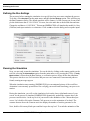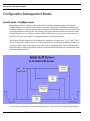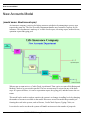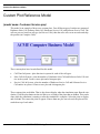
1
Getting Started SIMPROCESS Release 5 Copyright © 2002-2015 CACI, INC.-FEDERAL All rights reserved. No part of this publication may be reproduced by any means without written permission from CACI. The information in this document is believed to be accurate in all respects. However, CACI cannot assume the responsibility for any consequences resulting from the use thereof. The information contained herein is subject to change. Revisions to this publication or new editions of it may be issued to incorporate such change. SIMPROCESS is a registered trademark of CACI, INC.-FEDERAL. Table of Contents CHAPTER 1 Business Process Modeling With SIMPROCESS......................... 9 What is Process Mapping? Why Map Business Processes?...... 9 What is Process Simulation?........................................................ 9 What is Activity Based Costing? ............................................... 11 What is SIMPROCESS? ............................................................ 13 What Makes SIMPROCESS Unique? ...................................... 14 SIMPROCESS Editions ............................................................. 17 SIMPROCESS Modeling Constructs and Terminology ......... 18 Advanced Modeling Functions .................................................. 23 How Does SIMPROCESS Work? ............................................. 26 SIMPROCESS Applications ...................................................... 28 CHAPTER 2 Installation.................................................................................... 29 SIMPROCESS Requirements ................................................... 30 Installing SIMPROCESS ........................................................... 31 SIMPROCESS Directory Structure.......................................... 32 SIMPROCESS Working Directory........................................... 35 Starting SIMPROCESS ............................................................. 36 Installing SIMPROCESS on Local Area Networks................. 37 Getting Technical Support ......................................................... 37 CHAPTER 3 Building Your First Model With SIMPROCESS ........................ 38 Model Description and Objectives ............................................ 38 Defining the Resources and Their Usage .................................. 53 Simulating the Process................................................................ 56 Analyze the Performance Measures.......................................... 59 SIMPROCESS Getting Started Manual 3 Table of Contents CHAPTER 4 Evaluating Alternatives With SIMPROCESS............................. 61 The To-Be Process Description and Tutorial Objectives ........ 61 Simulate and Analyze the To-Be Process ................................. 65 CHAPTER 5 Demonstration and Reference Models ........................................ 67 Call Center Model....................................................................... 68 Cashier Process Model ............................................................... 70 Configuration Management Model ........................................... 71 Credit Issuance Process Model .................................................. 73 New Accounts Model .................................................................. 75 Supply Chain Model ................................................................... 77 Purchasing Process Model ......................................................... 79 Help Desk Model ......................................................................... 81 Assemble Reference Model ........................................................ 83 Batch/Unbatch Reference Model............................................... 85 Split/Join Reference Model ........................................................ 87 Entity Preemption Reference Model......................................... 89 Custom Plot Reference Model ................................................... 91 Remote Plot Reference Model ................................................... 93 Inventory Model.......................................................................... 95 Network Model............................................................................ 97 Human Resources Model ........................................................... 98 Justice System Model.................................................................. 99 Remote Application Call Model .............................................. 100 External Schedule Model ......................................................... 102 Emergency Room Model .......................................................... 104 Get Resource Reference Model ............................................... 105 Airport Staffing Model ............................................................. 107 BPEL Purchase Order Model.................................................. 108 Pools Model ............................................................................... 109 Database Demonstration Model .............................................. 110 SIMPROCESS Getting Started Manual 4 Table of Contents Spreadsheet Demonstration Model ......................................... 112 SIMPROCESS Getting Started Manual 5 Organization of the SIMPROCESS Documentation Set The SIMPROCESS documentation set consists of four manuals: • • • • Getting Started With SIMPROCESS SIMPROCESS User’s Manual SIMPROCESS Metadata Manual SIMPROCESS OrgModel Manual All of the manuals can be opened directly from the Help/SIMPROCESS Manuals menu. Also, each manual includes this section which provides links to the chapters in every manual. Press the Control key when clicking any link to open the linked file in a new window. For Windows systems, in order for links between manuals to work properly, Adobe Acrobat or Acrobat Reader must be used to view the manuals. Getting Started The Getting Started With SIMPROCESS manual is a must for first time SIMPROCESS users. This manual can also be used for evaluation purposes. The chapters are • • Business Process Modeling With SIMPROCESS Installation 6 • • • Building Your First Model With SIMPROCESS Evaluating Alternatives With SIMPROCESS Demonstration and Reference Models User’s Manual The User’s Manual is divided into four parts with each part being a separate file. Part A is an excellent reference for beginners and casual users. This part contains detailed documentation of the basic and intermediate functions of SIMPROCESS. The chapters are • • • • • • • • Process Modeling and Analysis with SIMPROCESS SIMPROCESS Basics Statistical Modeling Constructs Activity Modeling Constructs Resource Modeling Constructs Graphical Modeling Constructs Activity-Based Costing Statistical Output Reports Part B is a reference intended for advanced users of SIMPROCESS. This part contains detailed documentation of the programming and library management functions in SIMPROCESS Professional Edition. The chapters are • • • • Reusable Templates and Libraries Customizing a Model with Attributes and Expressions More Advanced Model Building Exporting Results Part C describes the integrated tools included with SIMPROCESS Professional. The chapters are • • • • • • • • Advanced Data Analysis SIMPROCESS Database Experiment Manager OptQuest for SIMPROCESS SIMPROCESS Dashboards Model Bundles Custom Reports Scenarios 7 The Appendices are • • • • • • • • • • • Importing Version 2.2.1 Models Activity Summary Table SIMPROCESS File Structure Statistical Distributions Statistical Tools Glossary SIMPROCESS System Attributes and Methods External Event Files Simulation Results File UML Interfaces Running Models Without GUI SIMPROCESS and External Java Classes Metadata Manual The Metadata Manual describes how to build and edit SIMPROCESS metamodels, assign metamodels to a SIMPROCESS model, and enter metadata in a SIMPROCESS model. The chapters are • • • • • SIMPROCESS Metadata SIMPROCESS Metamodel Editor Assigning Metamodels Entering Metadata BPEL Metadata OrgModel Manual The OrgModel Manual describes how to build and edit SIMPROCESS Organization and Resource Models (OrgModels) and assign OrgModels to a SIMPROCESS model. The chapters are • • • • SIMPROCESS Organization and Resource Models SIMPROCESS OrgModel Editor Assigning OrgModels Using OrgModels with SIMPROCESS 8 CHAPTER 1 Business Process Modeling With SIMPROCESS This chapter presents an overview of business process modeling with SIMPROCESS, its applications, unique features, basic and advanced modeling constructs, and benefits. What is Process Mapping? Why Map Business Processes? Understanding what a business does and how it does it requires documenting the inputs, processes, outputs, and resources. This is called process mapping. Process mapping combines the simplicity of flowcharting with the documentation features of word processing. Typically, executives and managers of industrial and service enterprises have managed their businesses by executive summaries and organizational charts without understanding the processes and their performance. However, executives and managers who are successful now are the ones that understand their business processes in detail. Process mapping includes several missing pieces from the organizational chart: the customers, the products, and the workflow. Process mapping shows how work actually gets done, which is through processes that cut across functional boundaries. The definition of boundaries provides managers with ability to define customer-supplier relationships through which products and services are produced. What is Process Simulation? Process simulation is the technique that allows representation of processes, people, and technology SIMPROCESS Getting Started Manual 9 What is Process Simulation? in a dynamic computer model. There are essentially four steps in doing business process simulation. They are: 1) building a model, 2) running a model, 3) analyzing the performance measures, and 4) evaluating alternative scenarios. A model, when simulated, mimics the operations of the business. This is accomplished by stepping through the events in compressed time while displaying an animated picture of the flow. Because simulation software keeps track of statistics about model elements, performance metrics can be evaluated by analyzing the model output data. Re-engineering gurus, Michael Hammer and James Champy, note in their book that only about 30 percent of the re-engineering projects they have seen were successful. One of the primary reasons for this low success rate is that often the analyses behind performance estimates of re-engineered processes have been prepared with flowcharts and spreadsheets. Business processes are much too complex and dynamic to be understood and analyzed by flowcharting and spreadsheet techniques. Although flowcharts and spreadsheets are adequate in answering “what” questions, they are inadequate for answering “how,” “when,” or “where” questions. This has resulted in overly optimistic performance benefits such as cost savings, throughput and service level increases that were promised by BPR (Business Process Reengineering). Typically, a BPR project begins with the end in mind where the end goal is to achieve one or all of the following objectives: • • • • • • Increase service level Reduce total process cycle time Increase throughput Reduce waiting time Reduce activity cost Reduce inventory costs BPR and IT (Information Technology) professionals often consider or recommend the use of basic principles in order to achieve the goals of a BPR project. Some of those principles are: • • • • • • • • • Combine duplicate activities Eliminate multiple reviews and approvals Automate repetitive tasks Reduce batch sizes Process in parallel Implement demand pull Outsource inefficient activities Eliminate movement of work Organize multi-functional teams SIMPROCESS Getting Started 10 What is Activity Based Costing? These principles clearly offer answers to the question of “What needs to be done?” to achieve the desired BPR objectives. But, re-engineering business processes involves changes in people, processes and technology over time. The key phrase here is “over time.” The interactions of people with processes and technology over time result in a large number of scenarios and outcomes that are impossible to comprehend and evaluate without the help of a computer simulation model. This is where simulation provides the greatest value for achieving BPR objectives. By tweaking decision variables in a model without the cost and risk of disrupting existing operations, or building a new system, one can accurately predict, compare, or optimize the performance of the re-engineered process. For example, the BPR professionals, who are designing the customer service process for a call center, must understand the random nature of calls arriving at the center, the random nature of processing times, the interdependencies between customer representatives, and the alternative routing schemes. They must take into account the dynamic nature of these behaviors in a model. If the performance goal is to achieve 100 percent service level or eliminate customer waiting times, a simulation of the process is absolutely necessary to accurately determine staffing requirements, telecommunications technology requirements, and how services are provided to the callers. What is Activity Based Costing? Activity Based Costing (ABC) is a technique for accumulating cost for a given cost object (i.e. product, service, customer) that represents the total and true economic resources required or consumed by the object. Activity Based Costing occurs in two phases. First, cost data is reorganized into activity cost pools. In other words, costs of significant activities are determined. This first phase is sometimes referred to as activity based process costing. Then, the amounts in the cost pools are assigned to products, services or other cost objects. The second phase is referred to as activity based object costing. SIMPROCESS Getting Started 11 What is Activity Based Costing? The goal of ABC is to model the causal relationships among resources, activities, and entities in assigning overhead costs. “The fundamental belief behind this costing approach is that cost is caused and causes of cost can be managed. The closer you can come to relating the costs to their causes, the more helpful your accounting information will be in guiding the management decisions of your business.” states the Ernst & Young Guide to Total Cost Management (Ernst & Young, 1992). Enterprises use resources to conduct activities. Resources perform activities to benefit products and services. The key to understanding cost dynamics in any enterprise is modeling the relationship between activities and their causes and modeling the relationship between activities and costs. If cost dynamics are not modeled (which is usually the case with traditional management accounting information systems), the performance information provided is incomplete or misleading. SIMPROCESS Getting Started 12 What is SIMPROCESS? What is SIMPROCESS? SIMPROCESS is a hierarchical and integrated process simulation tool that radically improves productivity for process modeling and analysis. SIMPROCESS is designed for BPR and IT professionals of industrial and service enterprises who need to reduce the time and risk it takes to service customers, fulfill demand, and develop new products. SIMPROCESS integrates process mapping, hierarchical event-driven simulation, and activitybased costing into a single tool. The architecture of SIMPROCESS provides an integrating framework for ABC. The building blocks of SIMPROCESS, namely processes, resources, and entities (flow objects), bridges ABC and dynamic process analysis. ABC embodies the concept that a business is a series of inter-related processes, and that these processes consist of activities that convert inputs to outputs. The modeling approach in SIMPROCESS manifests this concept, builds on it by organizing and analyzing cost information on an activity basis. SIMPROCESS Getting Started 13 What Makes SIMPROCESS Unique? What Makes SIMPROCESS Unique? SIMPROCESS is the first integrated tool that is specifically designed for business process modeling and analysis. SIMPROCESS combines process capture and event-driven simulation with activity-based costing. Here are some of the other features that distinguish SIMPROCESS from other modeling and analysis tools. Hierarchical, Event-driven Simulation SIMPROCESS is based on Java and XML (Extensible Markup Language). These underlying technologies provide hierarchical and event-driven simulation capabilities for modeling large scale applications. Unlike the hierarchical representations of processes using attached diagrams or files, SIMPROCESS offers true hierarchy based on object-orientation. Activity-based Costing The breakthrough activity-based modeling paradigm and resource constructs of SIMPROCESS offer a natural fit for its powerful activity-based costing engine., Activity-based costing is designed into SIMPROCESS, unlike other simulation tools, providing automatic cost reports. One of the major challenges in successful implementation of ABC is finding the appropriate level of detail for the business process analysis. The organization of business processes is critical to reorganizing the cost data into activity pools. The hierarchical modeling approach of SIMPROCESS facilitates this organization and accommodates varying levels of detail for ABC analysis. Methodology Independent Process Modeling Some of the process modeling tools require learning a new methodology such as IDEF or systems dynamics. SIMPROCESS provides a flexible process modeling environment that is adaptable to any methodology. The process documentation features of SIMPROCESS are far superior to typical flowcharting or simulation tools because it is specifically designed for business process modeling and analysis. Activity-based Modeling SIMPROCESS utilizes a breakthrough activity-based modeling paradigm. Real-world behavior of activities such as copying, assembly, transformation, batching, and branching are built into SIMPROCESS. These activities can be connected or embedded into processes using simple flowcharting techniques making process documentation quick and meaningful. These built-in activity blocks can even be customized to represent the operational characteristics of the business processes. SIMPROCESS Getting Started 14 What Makes SIMPROCESS Unique? Reusable Templates Reusable templates can be created from the basic building blocks and activities of SIMPROCESS. These templates can be saved in a library and made available to a cross functional team for reuse. This capability is a tremendous advantage for organizations that want to capture and maintain the most valuable asset of a business — the process knowledge. Advanced Modeling Constructs Most BPR tools that provide simulation functionality use simplistic modeling constructs. When modeling the dynamics of real-world business processes, powerful functions such as attributes, expressions, and IF-THEN-ELSE logic are needed. SIMPROCESS provides these advanced modeling functions and eliminates the limitations of simplistic tools. Powerful Resource Modeling Constructs Accurate resource modeling requires model building blocks that define the shared and consumable behavior of real-world resources. The powerful SIMPROCESS resource engine has flexible allocation schemes that provide realistic representation of real-world resource behavior. Comprehensive Statistical Analysis SIMPROCESS contains links to other tools. This suite of tools can be used to fit input data to a distribution and to analyze the results from multiple simulation runs. ModelFit is used to manually or automatically fit distributions to sample data during a simulation. Also, simulation results can be exported to a spreadsheet or database for detailed analysis. Multi-platform Support SIMPROCESS runs under Windows and Linux operating systems. (See “SIMPROCESS Requirements” on page 30.) Models are fully compatible across platforms—providing the flexibility to run large simulations on faster computers and take advantage of existing hardware. As hardware and operating system technology moves forward, SIMPROCESS will take advantage of them. Benefits of SIMPROCESS From superior technological capability to radical productivity improvement and reduced cost ownership, SIMPROCESS offers three major benefits over other BPR tools. These benefits are: SIMPROCESS Getting Started 15 What Makes SIMPROCESS Unique? Radical Productivity Improvement Because of the hierarchical and object-oriented modeling capabilities, SIMPROCESS enables cross-functional teams to work on projects simultaneously minimizing the time to get results. Dramatically Short Learning Curve Because SIMPROCESS provides a completely graphical modeling environment with flowchartinglike interface, it can be learned in a matter of hours. Significantly Reduced Cost of Ownership Because SIMPROCESS is an integrated process capture and analysis tool, it eliminates the need to purchase multiple products from multiple vendors. This combined with the availability of reusable templates significantly reduces the cost of product ownership over time. Benefits of ABC with SIMPROCESS Significant value of the ABC analysis in SIMPROCESS comes from the dynamic analysis of costs based on the event-driven simulation. Because SIMPROCESS keeps track of resource interdependencies and captures the random nature of processes, the cost statistics provided by SIMPROCESS are far more accurate than results obtained from static analysis. Benefits of ABC in SIMPROCESS: Focus on Cost Drivers One of the most important benefits of ABC is the focus it provides for estimating the key causes of costs. Executives can use these estimates to prioritize and monitor improvement efforts. For example, understanding the cost of poor quality can justify the investment in a quality program. Likewise, understanding the cost of complex or diverse products and services can help streamline the product and service offerings. Strategic Pricing Life cycles of product and services are becoming shorter and shorter. The up-front costs of developing, testing, and marketing are not recouped until revenue is generated. Understanding the cost trade-off between life cycle stages is critical to strategically pricing the products. That is, understanding when the total investment in product development can be recouped is valuable information for strategic pricing. ABC with SIMPROCESS allows simulation of the process changes during the life cycle of a product/service for strategic or time-based pricing. Evaluation of Capital Investments Reengineering business processes requires a trade-off between the benefits and costs of making process improvement changes. Without the trade-off, executives and managers are faced with making large investment decisions based on gut feel. ABC with SIMPROCESS provides an analytical tool for accurate evaluation of capital investments. SIMPROCESS Getting Started 16 SIMPROCESS Editions SIMPROCESS Editions SIMPROCESS has four editions: • Professional • University • Demonstration • Runtime The Professional edition contains all the features and capabilities of SIMPROCESS. There are no limits on model size for models built with SIMPROCESS Professional. The University edition also contains all the features and capabilities of SIMPROCESS. Model sizes are limited to no more than 50 processes and activities. Models built in the Demonstration edition are limited to no more than 25 processes and activities, 5 entity types, and 5 resource types. Also, none of the advanced features are available. The Runtime edition can run any model built in any SIMPROCESS edition. However, models built or edited in the Runtime edition cannot be saved. SIMPROCESS Getting Started 17 SIMPROCESS Modeling Constructs and Terminology SIMPROCESS Modeling Constructs and Terminology SIMPROCESS modeling constructs can be categorized into three major categories. The basic modeling constructs are the minimum functions needed to have a working model. The activity modeling constructs are used for defining the behavior of processes. The advanced modeling functions are the features needed for customization and more complex modeling. A brief overview of the SIMPROCESS constructs are presented below. Basic Modeling Constructs The diagram below illustrates the basic modeling constructs and how they are used in a SIMPROCESS model. Processes and Activities A key distinguishing feature of SIMPROCESS is its hierarchical process modeling capability. This allows decomposition of a process into as many levels of detail as required. The Process construct creates the hierarchy. A process may have several sub-processes and activities. For example, an inspection process that consists of a BRANCH activity and two DELAY activities can be defined as a hierarchical process template. Resources Resources are the second important modeling construct of SIMPROCESS. In the real world, the performance of a business process is usually constrained by the limited availability of resources or by resource interdependencies. SIMPROCESS defines the costs, capacity, usage, and interdependencies associated with resources. It automatically keeps track of the resource’s utilization and costs. Schedules and Downtimes can be modeled to mimic the dynamic behavior of resources. SIMPROCESS Getting Started 18 SIMPROCESS Modeling Constructs and Terminology Entities The third building block of a SIMPROCESS model is the Entities (or flow objects) that flow through the process model. Entities can be used to represent physical things (orders, paperwork), or logical things (signals, flags). Entities may be assigned attributes to define such characteristics as order size and customer type. Entities are created using the GENERATE activity and disposed using the DISPOSE activity. Connectors Connectors are the links between processes or activities. They are used for defining the flow of entities. Connectors are objects in their own right with characteristics, and they can have duration to represent travel time. Pads Pads are the objects used for linking connectors between processes or activities. A process may have multiple pads for input or output. Pads have three sizes: small (default), medium, and large. The default pad size can be set in the Preferences. Activity Modeling Constructs Activity modeling constructs are the objects at the lowest level of the SIMPROCESS hierarchy and they are used for modeling the behavior of a process. Activities are non-decomposable. The SIMPROCESS Model Toolbar contains 19 built-in activity blocks; however, re-usable activity templates can be created and added to the Library Toolbar. Below is a basic overview of the SIMPROCESS activity modeling constructs. SIMPROCESS Getting Started 19 SIMPROCESS Modeling Constructs and Terminology Generate A GENERATE activity generates the arrival of entities into the model. Arrivals may be random, deterministic or conditional. An example of a GENERATE activity is the arrival of patients in a clinic. A GENERATE activity may have values for arrival time, quantity, frequency and occurrences. Dispose A DISPOSE activity disposes of the entities when they are finished with processing. A DISPOSE activity can be used for collecting customized statistics for throughput or throughput time. Delay A DELAY activity defines value added or non value added activity times. It is one of the most commonly used activities in SIMPROCESS. A DELAY activity with resource constraints provides queue statistics that can be used for analyzing wait times. Assemble An ASSEMBLE activity assembles multiple entities coming from multiple sources to create a single entity. For example, the development of a business proposal may contain three documents that are merged using an assembly activity. Branch A BRANCH activity allows for defining alternative routings for flow objects. Branching may be based on a probability or a condition. For example, the outcome of an inspection process may be modeled using probabilistic branching. Merge A MERGE activity provides a mechanism for merging a number of connectors into a single connector. Batch A BATCH activity combines a given quantity of entities into a single batch. An example of a batching activity is the accumulation of mail for delivery. Unbatch An UNBATCH activity splits a previously batched entity into individual entities. For example, unloading of a truck that results in multiple loads may be modeled with an unbatch activity. Split A SPLIT activity takes an incoming entity and creates clones of that entity as well as providing an SIMPROCESS Getting Started 20 SIMPROCESS Modeling Constructs and Terminology output of the original entity. For example, clones of a purchase order may be created with a SPLIT activity and sent to accounts payable and shipping. Join A JOIN activity takes the clones and original entity that were split up, and matches them to produce the original one. For example, a JOIN activity may be used for matching the paperwork with the shipment. Transform A TRANSFORM activity converts an incoming entity into another entity. For example, a prospective buyer is transformed into a customer when an order is placed. This activity can be modeled using the transform construct. Transfer A TRANSFER activity routes entities from one portion of a model to another without using a connector, or routes entities to another model. Clone A CLONE activity makes multiple copies of the original entity. Note that this activity is not on the Model Toolbar. It is only on the Create menu in order to support pre-SIMPROCESS version 4 models. Gate A GATE activity holds entities in a queue, until a signal is received. For example, a GATE activity would be used to model orders held in inventory until a signal is received from the distributor to fulfill the demand. Assign An ASSIGN activity provides a mechanism for defining or changing attributes values. Synchronize A SYNCHRONIZE activity takes inputs that arrive at different times and outputs them in a synchronized fashion. For example, passengers and their baggage must be synchronized at a terminal. Replenish Resource This activity allows for replenishment of consumable resources. Get Resource This activity provides a mechanism for capturing resources that may be used for a number of downstream activities. SIMPROCESS Getting Started 21 SIMPROCESS Modeling Constructs and Terminology Free Resource This activity provides a mechanism for releasing resources that were captured by a GET RESOURCE activity. SIMPROCESS Getting Started 22 Advanced Modeling Functions Advanced Modeling Functions Advanced modeling functions are very important for realistically modeling the complex behavior of business processes. These functions of SIMPROCESS differentiate it from other BPR tools that are based only on simplistic modeling functions. The advanced modeling functions combined with programming capabilities provide the power and flexibility to accurately analyze the dynamic behavior of real-world business problems. User Defined Attributes Entity Types, Entity Instances, Resources, Activities and Processes, and the Model itself can have user defined attributes. User defined attributes can be used as tags attached to entities that travel through the model. Attributes can be used for conditional branching, sequencing, or decision making in expressions or logic. For example, order quantity may depend on which customer the order came from. Furthermore, order processing time may depend on the size of each order. By defining an attribute named “OrderQuantity” and writing an expression that multiplies “OrderQuantity” by “ProcessTimePerOrder,” the order processing delay can be accurately modeled. Built-in Attributes These attributes keep track of the states of model elements so that expressions can be written to deal with complex business situations. For example, the number of customers waiting for a service representative is a system attribute that changes over time. In a typical service process, the number of servers would be increased if the customers in line reach a certain number. User-defined Expressions When modeling real-world business processes, there will inevitably be situations which will require modeling functionality that is not built-into a BPR tool. SIMPROCESS provides the capability to write user-defined expressions and use them for modeling or customizing the performance measures. For example, service level may be an important performance measure for a business that is trying to fulfill orders within a 12 hour window from the time orders are placed. Using system attributes, user-defined attributes and user-defined expressions, the cycle time for each order can be compared with the 12 hour target and the service level of the process calculated. Built-in Programming Environment Although the built-in functionality and the ability to customize models with attributes, expressions, and distributions offer plenty of power for modeling most business processes, there may be situations where added flexibility is needed that can only be achieved by a programming environment. For these complex business process applications, SIMPROCESS has a built-in programming enviSIMPROCESS Getting Started 23 Advanced Modeling Functions ronment. Built-in & User-defined Distributions SIMPROCESS comes with 27 standard probability distributions and allows the creation of empirical distributions based on raw data. One of the powerful features of SIMPROCESS is its data analysis (curve fitting) functionality using ModelFit. ModelFit accepts a number of data points and then provides the distribution that best represents the data set. This can be done on-demand or automatically at the beginning of a simulation. Reusable Modeling Templates One of the most powerful features of SIMPROCESS is modeling templates can be created that can be stored in a library and used over and over. For example, an inspection process template using three SIMPROCESS activity blocks such as DELAY (inspection activity), BRANCH (probabilistic outcome of inspection), and DELAY (rework activity) can be created. A favorite inspection graphic can then be attached to the template and the inspection template saved in a library. When needing to model an inspection process, simply click on the inspection graphic, drop it in the model diagram, and double-click on it to customize its parameters. Event Logs Event logs are built-in features for tracking custom cycle time measures. Time Stamp event logs can be used for monitoring statistics such as makespan and in-process inventory. Recorder event logs can be used for monitoring statistics such as arrival and departure rates. Experiment Manager The experiment manager runs models automatically. SIMPROCESS loads the model, runs the replications, and (optionally) places the results in the database. Multiple models can be setup for simulation, and initial conditions can be varied for each model run. In addition, a text file of the results from each run can be automatically created. OptQuest OptQuest for SIMPROCESS is an optimization tool created by OptTek. Since OptQuest is an optimization tool, it attempts to minimize or maximize the value of a performance measure based on limits (constraints, upper bounds, and lower bounds). OptQuest automatically runs SIMPROCESS models varying the values for the model parameters searching for optimum results within the specified limits. SIMPROCESS Getting Started 24 Advanced Modeling Functions Dashboards SIMPROCESS Dashboards are collections of dynamic graphs that can be displayed locally or remotely by a Dashboard Server. The graphs contained by Dashboards can be of the same type or of differing types. Dashboards are defined independent of SIMPROCESS models. Thus, a Dashboard can be used with multiple models, or multiple models may use a single Dashboard. To use a Dashboard with a model, the Dashboard must be assigned to a model. The Assign process links the Dashboard to the model, indicates the location of the Dashboard Server for display (host or IP address and port), and sets the values that will be displayed on the graphs defined for that Dashboard. Custom Reports Custom reports are user-defined reports. They are defined for specific purposes and can contain statistical and non-statistical information. Custom reports are typically defined and viewed once all modeling, simulation, and analysis is complete. Multiple custom reports can be defined for a single model. Each report displays in a report viewer. From that viewer reports can be printed or saved in various file formats (for example pdf, rtf, and docx). Scenarios Scenarios are used to save simulation results for comparison purposes and are specific to a model. Thus, Scenario results from different models cannot be compared directly in SIMPROCESS. A Scenario is defined, and then the model is run with the Scenario selected. When the simulation completes the results from the Scenario are saved into an external file (Scenarios.xml) for later use. Scenario Reports can be created to compare results from different Scenarios or within the same Scenario. TimeServer SIMPROCESS models have the ability to let an outside agent manage the advancement of simulation time. That agent is the SIMPROCESS TimeServer. The TimeServer is a separate application that manages simulation time for multiple participants. (See SIMPROCESS TimeServer.pdf in the timeserver directory.) SIMPROCESS Getting Started 25 How Does SIMPROCESS Work? How Does SIMPROCESS Work? SIMPROCESS uses four easy steps to model processes. Step #1. Create The Process Model Creating a process model using SIMPROCESS is as easy-as 1-2-3. First, graphically select activities and processes from the Model Toolbar and link them using connectors to define the process flow. Second, define the entities (or flow objects) and resources used in the model. Third, customize the behavior of the model and create a realistic model of the business process by filling in the properties dialogs. It’s that simple! Step #2. Simulate The Process Before simulating the model, select the performance measures of interest. For example, throughput and cycle time reports for entities, activity costs for processes, and utilization reports for resources might be of interest. When the simulation is run, SIMPROCESS automatically verifies the model and begins advancing the simulation clock. During the simulation, SIMPROCESS displays an animated picture of the flow that helps to visualize the process in motion. SIMPROCESS can also generate real-time graphs, which display key performance measures, during the simulation. SIMPROCESS Getting Started 26 How Does SIMPROCESS Work? Step #3 — Analyze the Results When the simulation is over, bring up the model results and analyze the performance measures of interest. In addition to the automatically generated cycle time, throughput, waiting time, resource utilization and cost reports, custom reports for tracking service levels or in-process inventory can be generated. All SIMPROCESS reports can be viewed within SIMPROCESS or exported to other software packages. Step #4. Evaluate “Alternatives” The primary purpose of using SIMPROCESS is to evaluate alternative business decisions. To facilitate this important decision support activity, SIMPROCESS provides a unique function called “Alternative Sub-processes”. The “Alternative Sub-processes” function creates alternative representations of a business process utilizing its object-oriented interface. This powerful function is used to setup business alternatives. When simulations are run, the alternatives can be compared to choose the one that maximizes service levels and profits. SIMPROCESS Getting Started 27 SIMPROCESS Applications SIMPROCESS Applications SIMPROCESS provides a rich array of integrated functions for modeling and analysis of business processes. From customer service to product development, from administrative to production processes, for every business process, SIMPROCESS offers the ability to visualize and evaluate the results of process changes before expensive resources, time, and money are expended. Below are three applications where SIMPROCESS was used for effective business decisions. An Order Fulfillment Application A major Fortune 100 industrial enterprise was faced with a problem in one of its computer products business due to high inventory and low service levels. The proposed solutions included reduction of channel inventory and building product to order. SIMPROCESS was used in the re-engineering project that resulted in a 50 percent reduction in inventory and a 63 percent increase in service level. A Licensing Process Application A State Government hired CACI to help re-engineer its business processes that suffered from long service time and high cost per transaction. The proposed solutions included implementation of an automated work flow and imaging system as well as a full service counter. SIMPROCESS helped analyze the alternative solutions that increased throughput time from 80 days to 56 days, and reduced cost from $70 to $46 per transaction. An Engineering Change Order Application A major European automotive manufacturer was trying to shorten the time required for design changes in its product development process. The design changes originated in Europe and were implemented in South America. The business processes involved resources from designers to process engineers to purchasing agents. First, SIMPROCESS was used to create process maps and simulations of the As-Is process. Then, To-Be alternatives including policy changes and work flow automation were simulated to determine impact on cycle times. SIMPROCESS Getting Started 28 CHAPTER 2 Installation This chapter provides the minimum and recommended platforms for SIMPROCESS and the installation instructions for those platforms. If assistance is needed with installation, instructions are provided for getting technical support from CACI. SIMPROCESS Getting Started Manual 29 SIMPROCESS Requirements SIMPROCESS Requirements One of the unique features of SIMPROCESS is that it runs on multiple platforms. Before installing SIMPROCESS, review the hardware and software requirements and make sure that the system meets the minimum requirements. System Requirements Operating System Minimum Requirements Recommended Windows XP, Vista, 7, 8 (Desktop Screen only), or Server 2003, 2008, 2012 512 MB RAM 1024 MB RAM Linux Intel x86 or compatible processors only. More RAM is always better. The Gnome and KDE desktop environments should work. Try in the Linux environment to be sure it works correctly. Note for Windows Users: Administrator privileges will be needed to install SIMPROCESS, create the hostid.txt file, and place the license file in the SPSYSTEM directory. Also, in order for links between manuals to work properly, Adobe Acrobat or Acrobat Reader must be used to view the manuals. Note for Linux Users: The licensing software in SIMPROCESS has been certified against Linux Standard Base (LSB) 3.0. A list of certified distributions is at <http://www.linuxfoundation.org/ lsb-cert/productdir.php?by_lsb>. SIMPROCESS should work on any Linux distribution certified against LSB 3.0 or higher if it supports Sun's Java Runtime Environment and a 32-bit x86 architecture. Please review these requirements carefully before installing SIMPROCESS. SIMPROCESS Getting Started 30 Installing SIMPROCESS Installing SIMPROCESS SIMPROCESS can be download via the World Wide Web at www.simprocess.com or can be requested on a CD. To install SIMPROCESS: • • On Windows run install.exe, and on Linux run install.bin. • The next panel will ask where to install SIMPROCESS and provide a default location. Choose an appropriate location or accept the default, then click Next. • The next panel displayed will be entitled Choose Install Set. The SIMPROCESS install set is the default selection and should be used by most users. The SIMPROCESS and Dispatcher install set includes all the components for operating SIMPROCESS as a desktop application, plus a directory named dispatcher as well as a new Dispatcher application in the installation directory. The Dispatcher components are licensed separately from the SIMPROCESS, so choosing this install set unnecessarily will only consume disk space. • The next panel will offer options as to where to install program icon files, and finally a summary panel will then be shown. After all installation options have been selected, click the Install button to proceed with the installation process. • After all items are installed, there will be a series of dialogs that set the locations of some programs referenced by the SIMPROCESS application. The values entered here (if any) will become part default values for use in the program preferences and can be changed at any time. So if the locations are unknown or perhaps those program are not installed, select Cancel in response to these dialogs. On Windows systems only, SIMPROCESS will install a Microsoft Access database. Linux users should note that their systems may not contain the “suggested” default programs for text editor, spreadsheet program, etc. In order to work, the selected programs must be able to operate in an X Window environment. • Installation is now complete. The installer panel will show where the files were installed, and clicking “Done” will quit the installer program. • Run the hostid batch file or script in the SIMPROCESS directory. On Windows, the hostid batch file can be run from the Start Menu. This will place licensing information in the file named hostid.txt. Send this file to CACI ([email protected]) or the local License Administrator to obtain a license file and instructions for activating SIMPROCESS. • Once a license file (license.dat) has been obtained, place it in the SPSYSTEM directory and test the installation. (See “Starting SIMPROCESS” on page 36.) • Setup the Data source (See “Installing SIMPROCESS on Local Area Networks” on page 37.). The first step in the installer will be to display a License Agreement. Read the text and, assuming agreement, select the appropriate button, then click Next to continue with installation. SIMPROCESS Getting Started 31 SIMPROCESS Directory Structure SIMPROCESS Directory Structure The installation program creates the following directory structure in the location selected. Appendix C of the SIMPROCESS User’s Manual Appendices contains a more detailed listing of the files installed (see “SIMPROCESS File Structure”). Some of the directories listed below are installed in the user’s home directory (see “SIMPROCESS Working Directory”). Many of these directories can be opened in the system file explorer from the File menu (File/Open Directory). SPSYSTEM This directory contains numerous SIMPROCESS “system” files required to run the program. When a license file is received from CACI or the local license administrator, that file needs to be placed into this directory in order for SIMPROCESS to run. models When opening or saving models, SIMPROCESS initially starts in this directory. The demo and reference models are located here in the Demos and ExpressionDemos subdirectories. SPUser This directory holds the Microsoft Access database file (SimProcDB.mdb) on Windows systems. The related properties file (sProcDB.properties) will be placed here on all systems and must be present (and correct) in order to use the database included with SIMPROCESS. For those using Linux (or Windows users wishing to use another database environment), the file simprocessdb.sql contains DDL statements tested with MySQL to create a database named “simprocess” with the necessary tables and data for use with the Experiment Manager. This file can be used as a template for other database environments. There is also a file named mysql.sProcDB.properties to serve as a template for using a local copy of MySQL with SIMPROCESS. The “jdbc.drivers” property entry must refer to the name of a Java class which implements a Java driver for the database. JAR files containing the needed driver(s) should be placed in the installed JRE’s extensions directory (jre/lib/ ext) in order to be available at runtime. User preferences will be stored in this directory after SIMPROCESS runs. Importing graphics files for use as icons or backgrounds, or saving Libraries, will create a file here named UserFiles.jar. Previous SIMPROCESS Databases The Access database included with SIMPROCESS has changed over time. The latest change to the database was in SIMPROCESS 4.6, support for Resource by Shift statistics was added. Connector statistics were added in SIMPROCESS 4.2. Earlier changes included the addition of the StatType table and the removal of the Experiment Manager tables. Previous versions of the Access database will continue to work as long as the newer statistics are not collected during a simulation run. SIMPROCESS Getting Started 32 SIMPROCESS Directory Structure IMPORTANT: The installer will query as to whether to install a new Access database file if one is already present when installing over a previous release of SIMPROCESS. To use an earlier version Access database or employ methods below which allow both, move or rename the file SimProcDB.mdb before installation in order to get both database files. SPHelp This directory contains the directories and files for the SIMPROCESS Help. jre This directory contains Java Runtime Environment components referenced by SIMPROCESS. ext This directory is for user created compiled Java classes that can be used by the RemoteCall and ExternalCall features of SIMPROCESS. See “SIMPROCESS and External Java Classes” in Appendix K of the SIMPROCESS User’s Manual Appendices for more information. dashboardserver This directory contains the files required to run Dashboard Server. See “SIMPROCESS Dashboards” for information on using Dashboards. metamodel This is the required directory for SIMPROCESS metamodels. See the SIMPROCESS Metadata Manual (SIMPROCESS Metadata) for more information on metamodels. orgmodel This is the required directory for SIMPROCESS Organization and Resource Models (OrgModels). See the OrgModel Manual (SIMPROCESS Organization and Resource Models) for more information on OrgModels. dispatcher This directory only exists if SIMPROCESS and Dispatcher was selected during the installation. The installed files are required to operate SIMPROCESS through a Web service. SIMPROCESS Getting Started 33 SIMPROCESS Directory Structure dispatchermodels This directory only exists if SIMPROCESS and Dispatcher was selected during the installation. Model files that are to be opened and run through the SIMPROCESS Dispatcher must be located in this directory. timeserver This directory contains the files required to run the SIMPROCESS TimeServer. See Chapter 3 of Part A of the SIMPROCESS User’s Manual (Time Server) and SIMPROCESS TimeServer.pdf in this directory for more information on the TimeServer. SIMPROCESS Getting Started 34 SIMPROCESS Working Directory SIMPROCESS Working Directory Many organizations restrict application directory permissions. Since SIMPROCESS requires write permissions for various functions, several of the directories mentioned in the previous section are installed in the user’s home directory. A SIMPROCESS directory is created in the user’s home directory and the SPUser, models, metamodel, orgmodel, dashboardserver, and timeserver directories are installed in that location. Also, various other configuration files (such as the preferences file) and all log and error files are located here. Typical directory structures are • • • Windows XP - C:\Documents and Settings\username\SIMPROCESS Windows 7 or 8 - C:\Users\username\SIMPROCESS Linux - /home/username/SIMPROCESS where username is the user’s account name. This directory can be opened in the system file explorer from the File menu (File/Open Directory/Working). Note: The SIMPROCESS working directory and the SIMPROCESS installation directory will be the same on Linux systems if the default installation location is used. SIMPROCESS Getting Started 35 Starting SIMPROCESS Starting SIMPROCESS To start SIMPROCESS and test the installation: 1. A SIMPROCESS icon was placed on the desktop during installation, or find the SIMPROCESS executable in the location specified at installation time (in Windows, look in the program group on the Start Menu that was selected at installation; by default, it’s named SIMPROCESS). Double-click the appropriate icon or start the program by means appropriate to the platform. 2. From the SIMPROCESS main menu, select the File/Open option. 3. Select one of the demonstration or reference models (located in the Demos subdirectory of the models directory) and open the file. 4. Click on the Runner icon in the tool bar to start running the demo model. The installation and licensing process was successful if a demonstration model can be loaded and run. If there are problems installing SIMPROCESS, please contact CACI’s SIMPROCESS Technical Support at [email protected] or 703.679.3340. SIMPROCESS Getting Started 36 Installing SIMPROCESS on Local Area Networks Installing SIMPROCESS on Local Area Networks SIMPROCESS is designed as a single-user application intended to run on individual systems or workstations. Installing it on a server and providing access to multiple users simultaneously will create problems with concurrent file accesses. Each individual user should have a separately installed copy, although these may reside on a single server system. Getting Technical Support CACI provides worldwide technical support for its licensed users from its corporate offices in Virginia. Our office hours are from 8:00 a.m. to 5:00 p.m. Eastern time. To reach SIMPROCESS Technical Support by phone call 703.679.3340. In order to expedite responses to technical problems or questions, please use e-mail to send questions to [email protected]. Please include a customer number and the release and build numbers that appear under the Help/About SIMPROCESS menu item when reporting problems. If a model demonstrates the problem encountered, please attach the compressed model file (along with the simprocess.log and/or simprocess.err files if either is not empty) to the e-mail. The simprocess.log and simprocess.err files are located in the SIMPROCESS Working Directory. SIMPROCESS Getting Started 37 CHAPTER 3 Building Your First Model With SIMPROCESS This chapter gets you started with your first SIMPROCESS model. The purpose of this chapter is to familiarize you with creating a basic SIMPROCESS model, simulating the process, and analyzing the performance measures of the process. First, a description of the tutorial model is given. Then, a step-by-step tutorial is provided. Model Description and Objectives This model is a description of a call service process for a mail order business. Calls arrive at the mail order business and are routed by an automated answering system to either the customer service or sales department. Customer Service Calls arrive based on an Exponential distribution with a mean value of 6 minutes. This means that a call arrives on average every 6 minutes. Sales calls arrive based on an Exponential distribution with a mean value of 3 minutes. While the customer service calls take about 15 minutes (use Normal Distribution with a mean of 15, and a standard deviation of 3), the Sales calls take about 6 minutes (use Triangular Distribution with a minimum of 3, mode of 6, and maximum of 12 minutes). It is assumed that all Sales calls are for placing sales calls. The departments are staffed with 3 customer service (at $15 per hour) and 4 sales representa- SIMPROCESS Getting Started Manual 38 Model Description and Objectives tives (at $12 per hour). NOTE The time units on Delay Activities default to Hours. So when you create your model, make sure you change the time units to Minutes for the distributions. The purpose of this SIMPROCESS exercise is to build a model of the call service process and analyze the performance measures of the process. Specifically, the performance measures of interest are total processing time, wait time, resource utilization, and activity costs. Creating the Process Model Creating your first SIMPROCESS model involves 3 simple steps: • • • Mapping the Process Defining the Activities and Work Flow Defining the Resources and Their Usage Mapping the Process As mentioned in Chapter 1, SIMPROCESS is the first hierarchical modeling tool that combines process mapping with simulation. Let’s begin our tutorial by mapping the call service process. Let’s first define 3 major processes, namely, Generate Calls, Process Calls, and Complete Calls. To define the first major process, simply click on the Hierarchical Process icon in the Layout Toolbar (the uppermost icon on the toolbar, next to the pointer), drag the mouse, and drop it on the layout. Notice that SIMPROCESS assigns a default name called Process1 for the object you placed on the layout. Also, notice that each process box has one input and one output pad. You will later use these pads as the connection points between the processes. SIMPROCESS Getting Started 39 Model Description and Objectives Once you’ve placed the Process icon on the layout, you can size it, move it, and even cut and paste it. Now, let’s define the name of this process as “Generate Calls,” and change the icon. To accomplish this task, you need to bring up the Properties dialog for this object. There are 3 ways to bring up the properties dialog of a hierarchical process that has been selected: 1) Clicking on the Properties button in the tool bar (the button next to the Clear tool), 2) Choosing the Edit/Properties option from the main menu, or 3) Right mouse clicking on the process and choose Properties from the pop up menu. Let’s click on the Properties button and bring up the dialog. SIMPROCESS Getting Started 40 Model Description and Objectives The Name field contains the default name, “Process1,” that is displayed below the process box in the layout. You can change this name or disable the Show Name option. For now, let’s leave it as is. Also, on the Icon list notice that DefaultIcon is selected. In addition to the name, you can display text inside the process box graphic on the layout. To accomplish this task, click on the Text Block tab. In Line 1 Text type “Generate”. In Line 3 Text type “Calls”. When you close the properties by clicking OK, the text label will appear on the process. Based on your Font Attributes selections, you may need to resize the process for the label to fit. If so, select the process then choose Resize from the Edit menu. One of the useful process documentation features of SIMPROCESS is the Comment field in the properties dialog. For this process, let’s type in “This process generates 2 types of calls.” Click OK to accept the input and close this dialog. SIMPROCESS Getting Started 41 Model Description and Objectives To define the second process, click on the Process icon from the Layout Toolbar and drop the process to the right of the first process in the layout. Then, click on the Properties button in the tool bar to bring up the Properties dialog. Let’s label this process by clicking on the Text Block tab and typing in “Process Calls”. In the Comment field, type in “As-Is Process with 3 Service and 4 Sales Reps.” You will create a To-Be alternative of this process in the next chapter. To define the third process, place it on the right-hand side of the layout, repeat the steps described above, and label it “Complete Calls.” You now have 3 processes in your layout. Resize the processes if necessary. To resize, select the processes and choose Edit/Resize. SIMPROCESS Getting Started 42 Model Description and Objectives Next, let’s define the work flow by connecting the 3 processes using the Connector tool from the Layout Toolbar. Note that SIMPROCESS gives you two types of connectors. One type is a straight connector (diagonal button) and the other type is a bent connector. For this tutorial, let’s use the bent connectors. First, let’s connect the Generate Calls to Process Calls. Select the Connector tool from the Layout Toolbar and click on the right hand pad (small triangle) of the Generate Calls process. Then, click on the left pad of the Process Calls process. When you click on the left pad of the Process Calls process, the connector between the two processes will appear. Repeat this task to connect the Process Calls process to the Complete Calls process. Next, click on the left (input) pad of the Generate Calls process and click the Clear button on the tool bar or press the Delete key on the keyboard. Since nothing is entering this process, the input pad is not needed. Do the same thing for the right (output) pad of the Complete Calls process. That pad is not needed since no entities are leaving the process. When you are done, your model should look like the figure above. As you can see, mapping your process with SIMPROCESS is as quick and simple as flowcharting! While SIMPROCESS gives you the benefits of flow diagramming, it also provides you with the benefits of object-oriented simulation. The 3 processes that you just placed on the layout during the process mapping step are hierarchical objects. You can drill down inside each process and define its sub-processes. Unlike the attached diagram relationships in flowcharting based simulation tools, in SIMPROCESS, the relationships between hierarchical processes are based on object oriented modeling. In other words, the sub-processes not only inherit the graphical symbols of the hierarchical process but also their behavior. This provides the major benefit of re-usability. In this tutorial, you will drill down one level within each process; however, there is no limit to the SIMPROCESS Getting Started 43 Model Description and Objectives number of levels you can drill down. To practice drilling down, simply select a process and double click on it. You can also drill down by using the View/Descend menu item, or by using Descend on the right click menu, or by clicking the down arrow on the tool bar. Notice that you have a new layout with an input pad on the left-hand side and output pad on the right-hand side of the layout. Also notice that SIMPROCESS keeps you informed as to where you are in the hierarchy by displaying the name of the parent process object for this current layer. To get back up, simply double click any blank space on the layout. You can also accomplish the same task by choosing the View/Ascend from the main menu bar, or choosing Ascend from the right click menu, or clicking the up arrow on the tool bar. Now, you are ready to create a hierarchical simulation model of your process by using the powerful activity-based modeling and resource modeling constructs. Defining the Activities and Work Flow At the lowest level of each hierarchical process object is an activity or activities that describe the behavior of that process. In this tutorial, you will define two GENERATE activities that describe the process called Generate Calls. You will define a BRANCH activity followed by 2 DELAY activities that describe the process called Process Calls. Finally, you will define a DISPOSE activity that describes the process called Complete Calls. GENERATE Activities -- The entities (or flow objects) that will be moving through your model are created with GENERATE activities. The first process in your model generates two types of calls. Let’s drill down inside the Generate Calls process by selecting that object and double-clicking on it. Since this particular process is the beginning of the tutorial exercise, you need not be concerned about the input pad. First, let’s define the GENERATE activity that generates the service calls. To do this, select the GENERATE activity tool from the Layout Toolbar and place it on the layout. Then, double-click on the graphic to get the dialog. SIMPROCESS Getting Started 44 Model Description and Objectives Let’s change the name of this activity to “Generate Service Calls.” Next, click on the New Entity button to define the service calls. This brings up the dialog that allows you to define new entities. Select the Add option, type in the name “Service Calls,” and click on OK. Notice that the name Service Calls appears in the Entity field. This field is a table that contains the names of all entities that are defined in the model. SIMPROCESS Getting Started 45 Model Description and Objectives Now, you are ready to define the interval between service calls. Select the Periodic1 schedule and click the Edit button. In this simple model, we will represent the time between customer service calls using an Exponential distribution. To define the Interval for service calls, click on the downarrow next to the Interval combo box to see the list of available statistical distributions. Select the Exponential distribution, that is, Exp(10.0). You will see Exp (10.0) in the distribution field where 10 is the default value for the mean. To change the mean value for the interval to 6, click on the Interval detail button (the button with three dots on it). Let’s do that and type 6 (minutes) in the mean field. Click on OK to complete the distribution selection. You can also edit the mean field by editing the distribution field directly. Select Minutes as the Time Unit. The default value for generation of calls in the Quantity field is 1, which is what you want for this model, so use default is correct. Also, the default value for Entity is Service Calls, so use default is appropriate. Click OK to close the Periodic1 schedule. Notice that the GENERATE activity gives you many other options. For example, you can use a data file, spreadsheet, or database to generate the calls instead of a statistical distribution. Or, you can create complex schedules and cyclical arrival patterns. For now, let’s click on OK and move on to defining the generation of sales calls. SIMPROCESS Getting Started 46 Model Description and Objectives To define the generation of sales calls, select a GENERATE activity again from the Layout Toolbar and place it on the layout below the first GENERATE activity. Then, double-click on its graphic to get its properties dialog. Let’s change the name of this activity to “Generate Sales Calls.” Next, click on the New Entity button to define the sales calls the same way we did for Service Calls. This brings up the dialog that allows you to define new entities or edit existing ones. Select the Add option, type in the name “Sales Calls.” Choose an icon for the Sales Calls from the Icon combo box, different than the one you used for the Service Calls. When you view the animation during the simulation run, we will be able to see which calls moving through the system are Sales Calls and which are Service Calls. Click on OK to close the Entity Type Properties dialog. Select the Periodic1 schedule, then choose Edit. In this instance use default for the Entity field is not appropriate since the name Service Calls is displayed in the Entity field of the Generate Sales Calls activity. To change it to “Sales Calls,” click on the down-arrow to see the Entity list and select Sales Calls from the Entity list. Now, you are ready to define the interval between Sales Calls. To define the Interval, click on the down-arrow to the right of the Interval combo box to see the list of available statistical distributions. Select the Exponential distribution again. Click on the Interval detail button and type 3 (every 3 minutes) in the mean field as the mean value for the distribution. Before closing the dialog for the Exponential distribution, click on the View button in the lower right-hand corner. SIMPROCESS provides you with this useful viewing facility so that you can visualize the probability density function for this distribution. When you are done viewing the curve, close that window to return to the dialog for the Periodic1 schedule. Select Minutes for the Time Unit, and click on OK. This returns you back to the Generate properties dialog. Click OK again to get back to the layout. At this point, you must do an important task to complete the description of the call generation proSIMPROCESS Getting Started 47 Model Description and Objectives cess. That is, you must connect the output pads of the two GENERATE activities to the output pad of the hierarchical process called Generate Calls. To accomplish this task, first select the Connector tool from the Layout Toolbar and connect the output pad of the Generate Service Calls activity to the output pad on the right-hand side of the layout. Then, repeat the same task by connecting the output pad of the Generate Sales calls activity to the output pad of on the right-hand side of the layout. Now, we are done describing the processes for the Call Generation process. Double-click on any blank area on the layout and get back up to the major process level of the hierarchy. Next, you will define the Process Calls process which consists of a BRANCH activity followed by 2 DELAY activities. To drill down inside the Process Calls process, select that process with the mouse and double-click on it. Notice that SIMPROCESS gives you an input pad on the left-hand side, an output pad on the right-hand side and a blank layout in the middle for placing the activities at this level. The Branch activity determines the routing of calls. From the Layout Toolbar, select the Branch activity and place it to the right of the input pad. Then, using the Connector tool connect the process input pad to the input pad of the BRANCH activity. This means that calls entering the Process Calls process will be the input to this branching activity. SIMPROCESS Getting Started 48 Model Description and Objectives Then, double-click on the BRANCH activity icon to get its properties dialog. Let’s change the name of this activity to “Route Calls.” By default, the branch type is set to Probability. Change this setting by selecting the Entity Type button and select OK to close this dialog. The DELAY activities represent the Customer Service and Sales activities. From the Layout Toolbar, select a DELAY activity and place it to the right of the BRANCH activity. Then, select the Connector tool and connect the BRANCH activity to this DELAY activity. SIMPROCESS Getting Started 49 Model Description and Objectives To specify which entities take this route, you need to double-click on the connector between the Branch and Delay activities. Inside the Branch Connector Properties dialog, the currently displayed Entity Type is the “Service Calls.” To display the name “Service Calls” in the layout, type it in the name field and check the Show Name box. Click on OK to close this dialog. Next, double-click on the DELAY activity graphic to define its properties. Let’s change the name of this activity to “Customer Service” and define the duration for servicing a Customer Service call. The Duration field is a combo box much like the Interval field in the GENERATE activity. To define the duration, click on the down-arrow next to the combo box and select the Normal distribution (Nor). Then, define the parameters of the distribution (15 for the mean and 3 for the standard deviation). Again select Minutes for the Time Unit. Notice that one of the tabs in the Delay Properties dialog is for defining Resources required for this activity. You will do that after completing the work flow definition. Next, you need to define the DELAY activity representing the servicing of the Sales Calls the same way we did for Customer Service. To do this task, select the DELAY activity from the Layout Toolbar and place it to the right of the BRANCH activity just below the Customer Service activity. Then, select the Connector tool and connect the BRANCH activity to this DELAY activity. To specify which entities take this route, double-click on the connector and select the “Sales Calls” entity from the list of Entity Types on the right and then click the Add button to display the entity on the left. Then, type in the name “Sales Calls” in the connector name field and make sure the Show Name box is checked. This feature provides for meaningful documentation of the work flow. Click SIMPROCESS Getting Started 50 Model Description and Objectives on OK to close this dialog. Next, double-click on the DELAY activity graphic to define its properties. Let’s change the name of this activity to “Sales” and define the duration for servicing a sales call (triangular distribution, i.e., Tri, with a minimum of 3, mode of 6, and maximum of 12). Make sure to select Minutes as the Time Unit. To complete the description of the activities at this level, you need to connect the output pads of the Customer Service and Sales activities to the output pad that is on the right-hand side of the layout. At this point, the layout of your process should look something like the following figure. When you are done with those connections, you can get back to the major process level by doubleclicking in any blank space in the layout. The final task for completing the work flow is to describe the completion of calls. To accomplish this task, double click on the hierarchical process named Complete Calls. This activity is used for disposing of the calls after they are serviced. That is why the DISPOSE activity only has an input pad. For now, you need not define any parameters for this activity. Just select the DISPOSE activity from the Layout Toolbar, drag and drop it in between the two pads. Then, using the Connector tool, connect the input pad of the hierarchical process to the left side of the DISPOSE. When you are done making this connection, simply double-click in any blank space on the layout and go back up to the major process level. SIMPROCESS Getting Started 51 Model Description and Objectives At this point, you are through with the definition of your processes, activities and work flow. You are now ready to define your Resources and where they are required to perform work. SIMPROCESS Getting Started 52 Defining the Resources and Their Usage Defining the Resources and Their Usage One of the most powerful constructs of SIMPROCESS are the Resources. In this tutorial, you will define the Customer Service and Sales Resources, their capacity (quantity available) and hourly labor costs. You will then assign them to the appropriate activities. Resources are defined by selecting Resources on the Define menu or by clicking the Define Resources button on the Model Toolbar. Selecting the Resources option brings up the Resources list box. To define a Resource, click on the Add button, type in the name “Sales Rep” and define Units as 4. To define the hourly labor rate, click on the Cost tab and type “12” in the field called Cost per Time The Time Unit defaults to Hours. This means that each representative costs $12 per hour. During the simulation, SIMPROCESS will calculate the activity costs based the actual usage of the sales representatives. Then, click on the OK button to complete defining the “Sales Rep” Resource. Unit. SIMPROCESS Getting Started 53 Defining the Resources and Their Usage To define the Service Rep, click on the Add button of the Resources list box and repeat the same steps while setting the Units to 3 and hourly labor rate to $15. When you are done defining the Service Rep, click on the OK button. Then, click on the Close button of the Resources list box to get back to the layout. Now, you are ready to define how these Resources are used in processing calls. This task is accomplished by going into the activities that use the Resources. Drill down to the lower level of the hierarchical process named Process Calls. First, assign the Sales Rep to the Sales activity by doubleclicking on the DELAY activity representing Sales. While in the Sales activity dialog, click on the Resources tab. To define the Resource requirements for this activity, select the “Sales Rep” Resource and click on Add, leaving 1 as the default for the Units. This means one Sales Representative is required to perform this activity every time a Sales Call comes in. During the simulation, when a call arrives it will be serviced by one of the 4 Sales Representatives. If all Sales Representatives are busy, then the caller will wait in a queue until the next representative becomes available. SIMPROCESS will automatically keep track of the number of calls waiting, as well as how much time each call waited. Click on OK to close the dialog. To define the usage of the Customer Service representatives, select the “Customer Service” activity and repeat the same steps, again assigning one representative to each call that enters the activity. When you are done assigning the Resources to their corresponding activities, you are ready to simulate the process. Let’s go ahead and save the model now, before running the simulation. To save your model, select SIMPROCESS Getting Started 54 Defining the Resources and Their Usage the Save option under the File menu. Then, type in “As-Is” in the field next to File Name. Note that the file extension for SIMPROCESS models, .spm, is automatically assigned. So, your model file will be saved as As-Is.spm. Now, you are ready to simulate your process! SIMPROCESS Getting Started 55 Simulating the Process Simulating the Process Once you have completed building your model, simulating your process model involves 3 simple steps: • • • Defining the Statistics Collection Defining the Run Settings Running the Simulation Defining the Statistics Collection Before running the simulation, we need to define what statistics we wish SIMPROCESS to gather for us. SIMPROCESS provides you with a very flexible report generating system. As mentioned in the model description and objectives, the performance measures that we are most interested in are total processing time, wait time, resource utilization and activity costs. From the Report menu, select the Define Global Statistics Collection option. Collect Entity Statistics and Collect Resource Statistics should already be checked. If not, then select them. These are the default statistics collected by SIMPROCESS. When using this menu it is not necessary to individually request statistics for Entities, Resources, and Activities. SIMPROCESS Getting Started 56 Simulating the Process Defining the Run Settings The next step before running the simulation is to specify how long we want to simulate the process. To do this, select Simulate from the main menu, and then the Run Settings option. This will bring up the Run Parameters dialog. The default start date will be January 1 of the current year. In our example the default start date is “01/01/2014.” For now, leave the start date as the default date and time. Change the end date to “01/02/2014.” This means SIMPROCESS will simulate the model for 1 day (24 hours) and report statistics over that time. Click on OK to close the dialog and accept the inputs. Running the Simulation Now, you are ready to run the simulation. You can do this by clicking on the runner graphic on the tool bar, selecting the Simulate/Run option from the main menu, or by pressing the F4 key. If Verify Model on Run is selected on the Run Settings, a verification process occurs before the simulation. This process checks to see if all activities and processes are connected. If unconnected pads are found, warning messages appear. When the simulation starts running, SIMPROCESS gives an animated picture of the work flow. Animation is an extremely powerful tool for verifying your model and visualizing your process in motion. During the simulation, you will see the simulation clock on the lower right-hand corner of your screen. As the process is simulated, SIMPROCESS dynamically updates the counters above the processes and activities. At the top level of your model is the animation of the 3 hierarchical processes. Let’s double click on the Generate Calls process to see the animation of its detail. The counters that are above the Generate activities display the number of entities generated so far. Next, double click on any blank space and back up to the top level. To watch the animation of the SIMPROCESS Getting Started 57 Simulating the Process customer service and sales activities, drill down into the Process Calls process. The counters above the Branch and Delay activities show the number of entities currently in process. Now, move back up to the top level and descend into the Complete Calls process. The counter above the DISPOSE activity displays the number of entities processed so far. In this model, because both types of calls are sent to the same DISPOSE activity, the counter displays the total number of calls. In addition to these counters, you can display real-time graphs of cycle times, counts, and the number of calls waiting for service. Animation can be turned off anytime to speed up the execution of the simulation. This can be accomplished by deselecting the Animation On from the Simulate menu, by pressing F8, or by clicking the animation button (light bulb) on the tool bar. While the simulation is in progress, notice that the status bar in the bottom of your screen displays “Simulating” and “Trial 1 of 1.” When the simulation is over, you will notice that the status bar displays the message “Simulation Complete.” Once the simulation is complete, you are ready to analyze the output reports. SIMPROCESS Getting Started 58 Analyze the Performance Measures Analyze the Performance Measures Analyzing the performance measures for this model involves displaying the Standard Report Displaying the Standard Report To bring up the Standard Report, select the Report/Display Standard Report option from the main menu. The Standard Report can be displayed in a text editor or a spreadsheet. We will use text editor here. If the default path to NotePad is not correct, simply select the Browse button and choose a text editor application. Select Replication 1 and click Display Reports. First, we'll look at “Entity : Total Count - Observation Based.” This gives you the values of 460 for sales calls processed and 234 for customer service calls processed. “Entity : Cycle Time (in Hours) By State” shows that the average total processing time for a Sales call was about .12 hours (7.2 minutes) while the total processing time for a Customer Service call took about .36 hours (22 minutes). These times include the actual time for a call (in process time) plus the wait time. The average wait times are .007 (.42 minutes) for Sales calls and .102 (6 minutes) for service calls. Although the average wait time for sales calls is acceptable, an average wait time for customer service calls seems too long. An important question that comes to mind is “If the average wait time was 6 minutes, what was the maximum wait time for a customer service call?” The maximum wait times were .118 (7 minutes) for sales and .596 (35.8 minutes) for customer service calls. This means, of the 460 sales calls, the one that waited the longest had to wait 7 minutes and of the 234 customer service calls, the one that waited the longest had to wait about 36 minutes. Is this acceptable? For any mail order business that wants to be competitive, the answer is “Of course not.” No customer would wait 36 minutes before getting serviced. Most likely, they will hang up and try again. Or, they will take their business somewhere else. In the next chapter, you will create the To-Be process to reduce the maximum wait time for customer service calls. Now, we will look at the Resource statistics. “Resource : Number of Units By State” shows that average utilization of the Customer Service Representatives and Sales Representatives was over 2. Considering the fact that there were 4 Sales Reps and 3 Customer Service Reps available, this points out the possibility of over staffing in the sales department. However, you need to keep in mind that wait times were minimal for sales calls while they were considerable for customer service calls. If you were to reduce the sales staff to 3 units, what would happen to wait times for sales calls? You may want to try this alternative on your own after completing this tutorial. SIMPROCESS Getting Started 59 Analyze the Performance Measures Now let’s review the activity based costing statistics. Since you only ran the simulation for 24 hours, this means the costs were calculated for the 24 hour simulation run within the first week. There are three categories of costs: Resource by Activity, Resource by Entity, and Activity by Entity. In Activity by Entity you see that the activity costs are $643 for Sales and $900 for Customer Service activities. The proper interpretation of these costs is as follows: It cost $643 to service 460 sales calls and $900 to service 234 customer service calls. This adds up a total of $1,543 for serving 694 phone calls. Important Note: Please note that this simple exercise is intended to provide you with an overview of SIMPROCESS. In a typical business process simulation project, you would need to run this model for longer duration and for multiple replications before making conclusions about the results. SIMPROCESS Getting Started 60 CHAPTER 4 Evaluating Alternatives With SIMPROCESS This chapter shows you how to create and evaluate alternatives with SIMPROCESS. The purpose of this chapter is twofold: 1) to familiarize you with the unique process analysis feature Alternative Sub-processes, and 2) to improve the process that you modeled in the first tutorial. First, a description of the To-Be Process and tutorial objectives is given. Then, a step-by-step tutorial is provided. The To-Be Process Description and Tutorial Objectives In this tutorial exercise, you will create a To-Be alternative of the hierarchical process named “Process Calls” for the mail order business model developed in the previous tutorial. The To-Be alternative process uses customer representatives that are trained to process both the customer service calls and sales calls. So, instead of sales reps being dedicated to the sales activity and service reps being dedicated to the customer service activity, the new resources named “Customer Reps” will be flexible to service all calls coming to the Mail Order Business. The hourly cost for each customer rep is $15. The purpose of this SIMPROCESS exercise is to evaluate the process improvements that can be achieved by cross-training the service and sales representatives. Specifically, the objective is to reduce the maximum wait time for customer service calls from 36 minutes to under 8 minutes (.13 hour) while keeping the activity costs under $1,850 per 24 hours. Decision variables that you will tweak to meet the business objectives are the Units of Resources and the Hourly Cost per Unit. SIMPROCESS Getting Started Manual 61 The To-Be Process Description and Tutorial Objectives Create the To-Be Alternative Creating the To-Be alternative involves 3 simple steps • • • Define a new resource type called “Customer Rep” Define the To-Be alternative subprocess for the process called “Process Calls” Save the model under the name “To-Be,” and run the simulation Defining the New Customer Representative Resource From the main menu, choose the Define/Resources option. This brings up the Resources table. To define the new resource, click on the Add button, type in the name “Customer Rep” and specify the Units as 7. To define the hourly labor rate, click on the Cost button and type in “15” in the Cost per Time Unit. When you are done defining the cost for the new resource, click on the OK buttons and then the Close button until you are back to the layout. Creating the To-Be Alternative Process Select “Process Calls” and click on the Properties tool to bring up the dialog for this process. Notice that the list box contains the name “Alt1” in the Alternatives list box. Click on the Edit button and change the name to “As-Is.” Then click on the Copy button and type in the name “To-Be” for the new alternative you are about to create. Then, click on OK. Notice that the new alternative is highlighted, meaning that when you descend into the process you will be in the “To-Be” alternative. Click on OK and close the Properties dialog. You are now ready to define the sub-processes for the To-Be alternative of the “Process Calls” object. Double-click on the process box to drill down to the next level in the hierarchy. At this point, the layout looks exactly like the “As-Is” alternative. Remember that you had copied the contents of the “As-Is” alternative into the “To-Be” alternative. Next, you modify the resource assignments so that the resources used for performing work are the new “Customer Rep”. Let’s first double click on the Customer Service activity and click on the Resources tab. SIMPROCESS Getting Started 62 The To-Be Process Description and Tutorial Objectives To remove the Service Rep resource from this assignment, simply click on the Remove button while that resource is highlighted. Then, select the “Customer Rep” resource from the Resource tree and click on the Add button. This means that every service call will be handled by a Customer Rep instead. Click on the OK button to close this dialog and get back to the layout. SIMPROCESS Getting Started 63 The To-Be Process Description and Tutorial Objectives You also need to assign the Customer Rep to the Sales activity. To accomplish this task, repeat the same steps by removing the Sales Rep from the assignment and adding the Customer Rep to the resource assignment. You are now done creating the To-Be alternative process. So, double-click in any blank space in the layout and get back to the major process level. SIMPROCESS Getting Started 64 Simulate and Analyze the To-Be Process Simulate and Analyze the To-Be Process You are now ready to simulate the To-Be alternative process. So, go ahead and select the Simulate/ Run option (or click on the Runner icon in the tool bar). Since you did not change the As-Is alternative, it is still part of this model. However, when you run the simulation, SIMPROCESS will only simulate the To-Be alternative because that was the highlighted alternative when you left the Properties dialog of the “Process Calls” object. During the simulation of this alternative, double-click on the “Process Calls” hierarchical object to view the animation of the activity level. You may turn off the animation by pressing F8 or clicking the Animation button on the tool bar. When the simulation is completed, you will see that the Status Bar displays the message “Simulation Complete” indicating that SIMPROCESS is ready for you to edit the model or analyze the results. Analyze the Results of the To-Be Process Now, let's display the Standard Report. First, let's take a look at “Entity : Total Count”. This table shows that the redesigned process with 7 flexible Customer Reps serviced 475 sales calls and 252 customer service calls. Next, let's look at “Entity : Cycle Time (in Hours) By State” and analyze the wait time reduction for the To-Be process. This report shows that the average wait time for Sales calls was .01 (.6 minutes) and for Service calls was .009 (.54 minutes) indicating that the wait time for service calls was reduced dramatically. The maximum values for wait times are .092 (5.5 minutes) for the sales calls and .078 (4.7 minutes) for the customer service calls. These peak wait times are much more acceptable considering the fact that only one of the 475 sales calls had to wait 5.5 minutes and only one of the 252 customer service calls had to wait 4.7 minutes. Next, let’s take a look at the cost statistics. The customer service activity cost is $967 and sales activity cost is $843 adding up the total activity costs to $1,810. This means we were able to achieve our desired business objectives by keeping total activity costs under $1,850. Let’s close the Standard Report and the Display Standard Report dialog. SIMPROCESS Getting Started 65 Simulate and Analyze the To-Be Process Compare Performance Measures from As-Is with To-Be Let’s now compare the results from the As-Is process with the To-Be process. As-Is To-Be Report The table below summarizes the results: Sales Customer Service Total 460 234 694 As-Is Calls 475 252 727 To-Be Calls $643 $900 $1,543 As-Is Activity Costs $843 $967 $1,810 To-Be Activity Costs SIMPROCESS Getting Started 66 CHAPTER 5 Demonstration and Reference Models This chapter describes the demonstration and reference models that are included with the SIMPROCESS installation under the Demos subdirectory in the models directory. Running these models and studying the techniques used in building them will give a better appreciation for the activity modeling and advanced modeling constructs of SIMPROCESS. Included in the Demos directory, but not described here, are As-Is.spm (Chapter 3 Tutorial model) and To-Be.spm (Chapter 4 Tutorial model). Also included in the Demos directory is a model bundle example, InputSources.bundle. See “Extracting Bundle Files” for information on extracting a model bundle. The model in the bundle demonstrates SIMPROCESS Input Sources. See “Input Sources” for detail on defining and using Input Sources. The ExpressionDemos subdirectory contains models that demonstrate various aspects of the SIMPROCESS Expression Language. Located in ExpressionDemos is SIMPROCESS Expression Models.pdf, which discusses each model. SIMPROCESS Getting Started Manual 67 Call Center Model Call Center Model (model name: CallCenter.spm) Staffing of Call Centers has become a important issue for many companies today. Balancing staffing levels with the need to maintain the high level of service that consumers demand, requires complex analysis. In this model, three types of calls are generated: Type A, Type B, and Type C. Each call type has its own cyclical schedule, at a generate activity inside the Generate Phone Calls process. The center is staffed by 3 levels of Technicians: X, Y, and Z. • • • Question Type A can be answered by any of the three technicians Question Type B can be answered by a Y or Z Technician Question Type C can be answered only by a Z Technician SIMPROCESS Getting Started 68 Call Center Model The numbers of each type of Technician available in the model are model parameters. Each time the simulation is started, a dialog will open. The user change any of the model parameters from that dialog. By default, the incoming call buffer can contain no more than 10 calls on hold. If 10 callers are already on hold, the next incoming call will get a busy signal and be dropped. The maximum number of calls the buffer can hold is also a model parameter, the user will be prompted to change the queue’s capacity each time the model is run. If a call is on hold for too long (in the buffer) it will hang up (renege). This is done by setting the Entity system attribute MaxWait. MaxWait determines the amount of time an entity will wait to obtain a resource. If the resource is not obtained within the specified time, the entity exits the activity without processing. When this occurs the Entity system attribute EndWait is set to TRUE. This is demonstrated in the Accept Entity expressions of the branch activities Check Queue and Response. Note: If further processing is required, be sure to reset MaxWait to 0 and EndWait to FALSE. This model demonstrates the use of dynamic labels. The labels for Number of calls on hold and the labels in the column # of Calls are updated by setting a value for the label to monitor. The labels under the columns Answered, Balked, and Reneged are updated by using the SIMPROCESS expression statement UpdateDynamicLabel. These statements can be found the Accept Entity expressions of the dispose activities Balked Calls, Reneged Calls, and Completed Calls. The sample Dashboard Call Status.spd is included in the Demos subdirectory. This Dashboard is assigned to the Call Center model. To view the Dashboard while the Call Center model is running, select Tools/Remote/Start Local Dashboard Server. Once the Dashboard Server has been started, start the model. Make sure the animation is turned on. Once the model has been started, the Dashboard will appear. See Chapter 5 of Part C of the SIMPROCESS User’s Manual for a full discussion of SIMPROCESS Dashboards. SIMPROCESS Getting Started 69 Cashier Process Model Cashier Process Model (model name: Cashier.spm) This model also addresses staffing issues. Many organizations want to study how experience and training programs for employees will affect the quality of service given to their customers. In this model, we are using how long the customer will wait for a cashier as the measure of customer service. This simple model uses the Get and Free Resource activities. Two different resources are available to service the incoming customers, Cashiers and Trainees. The incoming customer will go to the first available, regardless of which of the two it is. The service time of the customer is dependent on which resource is servicing the customer. The Trainee will take slightly longer than the more experienced Cashier. Both resources have an expression which passes a value to a global entity instance attribute called “Cashier”. The value passed to the attribute on the Cashier is 1.0 and on the Trainee is 1.2. This value is passed to the customer when the cashier resource becomes available. The service time is calculated by an Evaluate Function on the delay activity, “Cashier Services Customer”. The function takes the value of the global entity instance attribute “Cashier” on the customer, that the customer got from the cashier resource, and multiplies it by the standard time. The time standard for servicing the customer is represented by the an exponential distribution with a mean of 12 (minutes). SIMPROCESS Getting Started 70 Configuration Management Model Configuration Management Model (model name: CnfgMgmt.spm) Responding quickly to changes in the market and to customer demands requires that Product Change Requests be processed as efficiently as possible. Long delays in handling and transportation mean changes to make the product more competitive and produced more cost effectively may not implemented on a timely basis. One strategy to decrease the time it takes to process a Product Change Request is to use electronic means to transfer them between the various parties involved. Workflow tools are one example of an implementation of electronic transfer. The Product Change Request Process contains two alternative sub-processes, “As-Is” and “To-Be”. The As-Is alternative models this process using standard mail to transport the Requests to the various parties whose input and/or approval are necessary for implementation. The To-Be alternative has essentially the same process map, with the exception that the Requests are electronically transmitted through the process. To view the two alternatives, ascend to the highest level of the model. Select the Change Request SIMPROCESS Getting Started 71 Configuration Management Model Process, and click on the Properties button on the System Toolbar. From the list of Alternative Subprocesses, select “As-Is” and the OK button. Descend into the Change Request Process. To change to the To-Be alternative, ascend to the top level of the model, open the Properties dialog of the Change Request Process and select “To-Be” from the list of Alternative Sub-processes. When the simulation is run, the output reports will reflect the currently selected sub-process. SIMPROCESS Getting Started 72 Credit Issuance Process Model Credit Issuance Process Model (model name: Credit.spm) This demonstration is a model of the IBM Credit Corporation’s reengineering example that is used in Hammer and Champ’s book Reengineering the Corporation (Harper Collins, 1993). The As-Is process, according to Hammer and Champy, took an average of six days, and sometimes as long as two weeks. Because of this delay, customers occasionally canceled deals. When two IBM managers decided to walk through the process and determine exactly how much time was required to process a loan request, they discovered that the process took only 90 minutes! They determined (apparently) that the delays were caused by “hand-offs,” or transfers between departments. At the top level, the Credit model contains 3 processes. The first process is a GENERATE activity that generates finance requests based on an interval that uses an exponential distribution with a mean value of 30 minutes. The second major process is a hierarchical representation of the business processes. The third process is a DISPOSE activity that marks the end of the process. As-Is Alternative The As-Is process for processing a finance request consists of 5 major sub-processes: 1) Log Request - Field sales personnel call in request for financing to group of 14 people. The person taking the call (Call Logger) logs the information on a piece of paper. The paper is taken upstairs to the Credit Department by a Courier. 2) Check Credit - A Credit Specialist enters the information into a computer and does a credit check. The result of the credit check is written on a piece of paper. The Courier takes the paperwork SIMPROCESS Getting Started 73 Credit Issuance Process Model to the Business Practices Department. 3) Add Special Terms - Standard loan contracts are modified by a Business Administrator to meet customers requirements. The request is then taken to a Pricer by the courier. 4) Price Financial Request - The pricer determines the interest rate. The interest rate is written on a piece of paper and taken to a clerical group by the courier. 5) Send Quote Letter - A quote is developed by an Administrator and sent to Field Sales via Federal Express. To-Be Alternative IBM management decided to reengineer the process by replacing the specialists with “deal structurers,” or generalists. In the reengineered process, the generalists handle the process from beginning to end. To facilitate processing, the generalists would receive assistance from a sophisticated computer system and, when there was a problem, would seek help from one of the remaining specialists. IBM decided to eliminate all hand-off delays and prioritize credit application processing by assigning personnel to handle the process from beginning to end. The To-Be process for processing the finance request starts out with a BRANCH activity where the nature of the finance request is determined. Ninety percent of the time a request is sent to a Generalist while ten percent of the time a request is sent to a team of resources consisting of a Generalist, an Administrator, a Credit Specialist, a Business Practitioner and a Pricer. SIMPROCESS Getting Started 74 New Accounts Model New Accounts Model (model name: NewAccount.spm) An insurance company is striving for higher customer satisfaction by attempting to process new requests the same day. The New Accounts Department handles new customer's requests for life insurance. This department is made up of: a credit check expert, risk rating expert, medical doctor, quotation expert and typing pool. When a new account arrives, a Credit Check is performed. Then copies are sent to Risk Rating and Medical Check to be processed in parallel. The new account may be rejected at any of the three steps. If it passes all three, it is sent to a quotation expert, the typing pool, and then sent to the customer. This model can be used to test how sensitive the system is to changes in staffing levels by changing the number of resources available in the model. Resources are used to model the personnel performing the work in the system, such as Doctors, Credit Check Experts, Typing Clerks, etc. It can also be used to test how the system will handle an increase in the number of proposals SIMPROCESS Getting Started 75 New Accounts Model requested. If, for instance, a marketing campaign was planned that was expected to increase the number of requests by 10%, the number of incoming requests to the model could be increased by the same amount. Running the simulation again, we can see how the system’s performance will be affected by the increase. SIMPROCESS Getting Started 76 Supply Chain Model Supply Chain Model (model name: Supply.spm) For an industrial enterprise, one of key business processes is the supply chain process. The primary goals of supply chain management are to maintain high service levels while minimizing costs. The key problem in supply chain management is how to balance inventory. Variability in demand and process times, complexity of the supply chain objects, and system dynamics create uncertainty that can only be modeled and analyzed with a tool like SIMPROCESS. This demonstration model represents a typical supply chain for an industrial enterprise with 4 factories (Reno, Denver, Fargo, and Richmond), 3 suppliers (Phoenix, Omaha, and St Louis), and 4 customers, or distributors (San Francisco, Dallas, Detroit, and Boston), in the United States. This high level model of the supply chain demonstrates how SIMPROCESS can help define the major processes, resources, and entities involved in providing products to customers. The model also demonstrates the power of the hierarchical simulation capability of SIMPROCESS. To view the power of hierarchical modeling, drill down into the Reno factory (Factory 1). Since travel time is important, the Connectors between factories, suppliers, and customers represent the distance between each of the locations. Each Connector at the top level determines the appropriate travel time between locations by dividing the distance in miles by the average miles per hour. The average miles per hour is a model parameter that can be changed before each run. Shipments from factories to customers require a Factory Driver Resource. The Factory Driver can only drive from 8am to 10pm. Shipments from suppliers to factories require 2 Supply Driver Resources. Thus, travel is not interrupted for shipments traveling from a supplier to a factory. Because Orders are transmitted electronically, Transfer Activities are used to send Orders from customers to factories. This reduces the number of Connectors required on the top level. Below is a brief description of the model elements. Customers Customers demand products from the factories. The customer process defines the frequency and quantity of demand from the factories. Suppliers Suppliers supply raw materials (supplies or components) to the factories. Each supplier produces different types of raw materials and ships to each factory. SIMPROCESS Getting Started 77 Supply Chain Model Factories Factories assemble the components, package the goods (inventory) and ship them to customers. A factory typically ships to customers in its geographic region. For example, the Reno factory receives 60 percent of its orders from the San Francisco customer and 40 percent of its orders from the Dallas customer. Such a model of a supply chain can be enhanced to answer questions such as: • • • • What if the demand for certain products from the east coast supplier doubles? What if the Phoenix supplier is having manufacturing problems with a product line? What if we use alternative transportation carriers to deliver products to customers? What if we outsource the assembly process? SIMPROCESS Getting Started 78 Purchasing Process Model Purchasing Process Model (model name: Purchasing.spm) The high degree of change in the business environment has created a new challenge for industrial and service enterprises. That challenge is to determine an organizational structure that minimizes administrative costs while maximizing service to its customers. Traditionally, managers have used organization charts to describe hierarchical structures and evaluate business decisions regarding changes to the organization. Unfortunately, these tools are no longer adequate because they do not take into account the process view and dynamics associated with administrative processes. Documenting the processes, understanding the dynamics of the business processes and activity costs in a changing administrative process can only be achieved with a tool like SIMPROCESS. This hierarchical model of a purchasing process consists of 5 major processes. They are: • • • • • Select Supplier Negotiate Terms and Pricing Prepare Purchase Order Place Purchase Order Audit Invoice The demonstration model highlights one of the powerful features of SIMPROCESS — the ability to create alternative representations of a hierarchical business process. In this model, the purchasing process object consists of 3 alternative organizational representations. SIMPROCESS Getting Started 79 Purchasing Process Model Alternative 1 — Functional, Centralized Purchasing The purchasing process is performed by centralized, functional organization where the five functions are performed by staff dedicated to each function. Alternative 2 — Product based, Decentralized Purchasing The purchasing process is performed by three decentralized, product organizations where the each product organization performs all 5 functions for its product line. Alternative 3 — Hybrid Purchasing The purchasing process is performed by a hybrid organization where the supplier selection and terms and pricing functions are performed by a centralized organization; and the other 3 functions are performed by decentralized, product organizations. This model is a simple demonstration model for OptQuest. OptQuest automatically searches for optimal values. To examine the optimization setup choose OptQuest from the Tools menu. OptQuest for SIMPROCESS is licensed separately from SIMPROCESS. Therefore, if OptQuest is not enabled on the Tools menu, contact the SIMPROCESS Sales Manager for information on licensing. How this model was setup for optimization is described in Chapter 4 of Part C of the SIMPROCESS User’s Manual (OptQuest for SIMPROCESS). This model is also a demonstration of Scenarios and Scenario Reports. Select Scenarios... from the Simulate menu to see the defined Scenarios. To see the defined Scenario Reports, choose Scenario Reports... on the Reports menu. See Chapter 8 of Part C of the SIMPROCESS User’s Manual for a full discussion of Scenarios and Scenario Reports. SIMPROCESS Getting Started 80 Help Desk Model Help Desk Model (model name: HelpDesk.spm) Today, customers are much more demanding and cost-conscious than they are 5 or 10 years ago. Increasing competitive pressures make it a tough challenge for service enterprises to maximize service quality while minimizing costs. Such performance metrics as waiting time and activity costs are critical to providing quality service and strategically pricing services. Typically, staffing and communication technology decisions for a customer service process have been made by analytical tools which fail to take into account the randomness and system dynamics that result in queuing. SIMPROCESS provides a complete set of statistical tools such as probability distributions, Data Analysis, and Design of Experiments; and advanced modeling features such as cyclical generation of entities, and resource downtimes. This demonstration model shows how SIMPROCESS can be used for modeling the random nature of a Help Desk. The Help Desk utilizes three types of Customer Service Representatives (CSR’s) to handle incoming customer calls. These CSR’s are modeled as resources. The three type of CSR’s are: CSRhelp Customer Service Representative trained to handle calls regarding transfer of ownership, power outage and billing inquiries. CSRpage Customer Service Representative trained to handle calls regarding paging inquiries. CSR Customer Service Representative cross-trained to handle calls regarding transfer of ownership, power outage, billing and paging inquiries. The hierarchical business process “Help Desk” contains two alternative ways of utilizing the same total number of resources. The business objective of this exercise is to best utilize the CSR’s to minimize the time customers spend on hold waiting for an available Representative. SIMPROCESS Getting Started 81 Help Desk Model Alternative 1 This is the “As-Is” process. When a call arrives, it is answered by the first available CSRhelp. The Representative determines what the inquiry is regarding. The CSRhelp then either passes the call to “Desk 2” if it is a paging inquiry, or else handles the call. If the call is passed to Desk 2, the customer is put on hold until a CSRpage is available. Alternative 2 This is the “To Be” version of the process. When a call arrives, it is answered by the first available CSR. The Representative determines what the inquiry is regarding and services the customer regardless of the category. SIMPROCESS Getting Started 82 Assemble Reference Model Assemble Reference Model (model name: Assemble.spm) This model is a simple example of how the Assemble activity is used. A list of component entities and their quantities is specified on the Assemble Activity. When all of the required component entities are present at the activity, a new entity is created. The component entities are either deleted when the new entity is created, or they are batched and carried with the new component. This is controlled by a check box on the Assemble Activity Properties dialog. There are two Generate activities, one Assemble activity, and one Dispose activity. Request Info Pack is the original entity in this model, and is created using a periodic schedule at the Request Info Package activity. The Requests follow the connector to the Assemble process. At the Assemble activity, the Requests will be combined with a Folder, Brochure and a Demo CD. The Folder, Brochure and Demo CD are re-supplied weekly or monthly based on calendar type schedules for each entity type. Once all four of the required entities are at the activity, a new entity is created, an Information Package. The component entities are now deleted, all of the statistics gathered on them are complete. The Information Package follows the connector out of the Assemble Process to Mail. Run the model to gather the statistics and display the reports. Typically, the statistic of most interest SIMPROCESS Getting Started 83 Assemble Reference Model when using the Assemble activity, is the Hold For Condition time of the entities. This will record the amount of time the component entities are held at the Assemble activity until the specified component entities have arrived. In this example, a Request Info Pack, Folder, Brochure and a Demo CD, are needed to build an Information Package. The Hold For Condition statistic will show the average or peak amount of time each component was held at the Assemble activity until all required component entities are available. For this example, we are most interested in how long the Requests for Information Packages had to wait before the pieces of the Information Package were all available. Essentially, we are seeing if our re-order strategies for the pieces of the Information Package is causing too long of a turn-around time for getting Information Packages out to prospective customers. The average Hold For Condition time for the Request Info Pack is 26 hours and the peak Hold For Condition time is 144 hours. This shows, that with this re-order strategy, Requests for Information Packages wait on average just over a day for all of the components for the Information package to be available. We also see that the longest wait is six days. This is probably not acceptable. In this simple example, no resources are required for any steps in the model, so the Wait For Resource time is zero. The Duration At Activity refers to the time the entities spent in a Delay activity, or time during a delay specified on any other type of activity. SIMPROCESS Getting Started 84 Batch/Unbatch Reference Model Batch/Unbatch Reference Model (model name: Batch.spm) This model is a simple example of how the Batch and Unbatch activities are used. The Batch activity will hold entities until the specified quantity of entities has accumulated, then a batch of those entities is formed. The Unbatch activity breaks the batch back down to its component entities. The Generate and Dispose activities are placed at the highest level of the model, with the Batch/ Unbatch process. Descend into the Batch/Unbatch process. Here there are three activities, a batch activity, delay activity and an unbatch activity. Mail is the entity in this model, and is created using a periodic schedule at the generate activity. The pieces of Mail follow the connector to the Batch/ Unbatch process. The first step in the process, the Batch activity, holds the Mail until ten pieces have accumulated. The “batch” of ten pieces of Mail moves to Delivery where it takes one hour to move the batch from the district office to a local office. Once the batch of Mail arrives at the local office, the Mail is unbatched. The ten component pieces of Mail are released and follow the connector out of the Batch/Unbatch process. Run the model to gather the statistics and display the reports. Typically, the statistic of most interest when using the batch activity, is the Hold For Condition time. This will record the amount of time the entities are held at the batch activity until the number of entities specified have arrived. In this example, ten pieces of Mail are needed for a batch. The Hold For Condition statistic will show the average or peak amount of time a piece of Mail was held at the batch activity until the specified number of pieces of Mail reached the activity and a batch was formed. In this example, the average Hold For Condition time is 2.25 hours and the peak Hold For Condition time is 4.5 hours. In this simple example, no resources are required for any steps in the model, so the Wait For Resource time is zero. Duration At Activity refers to the time the entities spent in a Delay activity, or time during a delay specified on any other type of activity. In this model, Duration At Activity measures the amount of time spent in the Delivery, which is one hour. One important last note, when the entities are unbatched, they regain the individual identity they had before being batched. For example, if a unique attribute was attached to each of the entities before they were batched, when they are unbatched, the individual entities will still contain their own unique value of that attribute. SIMPROCESS Getting Started 85 Batch/Unbatch Reference Model SIMPROCESS Getting Started 86 Split/Join Reference Model Split/Join Reference Model (model name: SplitJoin.spm) This model is a simple example of how the Split and Join activities are used and how to use Expression Plots. When an entity reaches the Split activity, a clone or clones of the entity are created. The original entity will exit the Split activity from the pad labeled “Original”. The clone entities will exit the Split activity from the pad labeled “Clones”. The number of clones made corresponds to the number of connectors that originate from the clones pad. The original entity and its clone(s) are referred to as a “family”. The Join activity will hold the original entity and its clone entities until the entire family has reached that activity. The original entity will then continue through the model, the clone entities are deleted by default, or can be batched with the original entity. The Generate and Dispose activities are placed at the highest level of the model, with the Split/Join process. Double-click on the icon representing this process to descend one level. Here there are four activities, a Split activity, two Delay activities, and a Join activity. Orders are the entity in this model, and are created using a periodic agenda at the Incoming Orders activity. The Orders follow the connector to the Split/Join process. The first step in the process, the Split activity, creates a clone of the Order, called “Invoice”. The Order then moves to Shipping where the Order is filled from stock on hand, when the Order moves to the Join activity. The Invoice moves to billing, when work is completed there, it moves to the Join activity. When both the Order and its matching Invoice arrive at the Join activity, they are batched and follow the connector out of the Split/Join process. Run the model to gather the statistics and display the reports. The model is preset to run 10 replications so either run the model for one replication or run all 10 replications and look at the report for Replication 1. Typically, the statistic of most interest when using the Join activity, is the Hold For Condition time. This will record the amount of time the entities are held at the Join activity until the original entity and all of its clones have arrived. In this example, an Order and its Invoice are needed. The Hold For Condition statistic will show the average or peak amount of time an Order or Invoice was held at the Join activity until the rest of its family reached the activity. In this example, the average Hold For Condition time for the Invoices is .925 hours and the peak Hold For Condition time is 3.526 hours. The average Hold For Condition time for the Orders is .687 hours and the peak Hold For Condition time is 10.206 hours. In this example, no resources are required for any steps in the model, so the Wait For Resource time is zero. Duration At Activity refers to the time the entities spent in a Delay activity, or time during a delay specified on any other type of activity. In this model, Duration At Activity measures the amount of time spent in the Shipping and Billing activities as they are the only Delays or duration’s in this model. This model also demonstrates creating plots with the SIMPROCESS Expression Language. Two plots are created, a Trace plot and a Histogram plot. These plots graph values from each replication, SIMPROCESS Getting Started 87 Split/Join Reference Model so the model must be run for multiple replications for the plots to be populated. (Turning off Animation will cause the replications to complete quickly.) The commands to create and populate the plots are in the Model Expressions (Define/Model Expressions or Define Model Expressions button on the Model Toolbar). See the section Expression Plots in Chapter 8 of Part A of the SIMPROCESS User’s Manual and the section Creating and Controlling Plots With Expressions in Chapter 2 of Part B of the SIMPROCESS User’s Manual for a full description. SIMPROCESS Getting Started 88 Entity Preemption Reference Model Entity Preemption Reference Model (model name: Preempt.spm) This model is an example of how higher priority entities can preempt the processing of lower priority entities. Two types of entities are generated, Routine Message and Urgent Message. The transmission of the messages is modeled by a Delay activity which uses the Transmitter resource. The Urgent Message entity has a higher Priority (priority 2) than the Routine Message entity (priority 1). Also the Preempt Lower Priority Entities option is selected. SIMPROCESS Getting Started 89 Entity Preemption Reference Model If an Urgent Message arrives while a Routine Message is processing, the processing of the Routine message stops. This causes the Transmitter resource to be released for the Urgent Message. Once the Urgent Message has completed processing, the Routine Message that was preempted obtains the Transmitter resource and completes processing. Note that the preempted entity does not start the processing over. The entity processes the amount of time that was remaining when preempted. Preemption can be further refined by using Expressions. Entities have a System Attribute called Interrupt. Individual entities can be set to preempt lower priority entities by setting this attribute to TRUE. Run the model and look at the Standard Report. Note that the Wait For Resources time is zero for the Urgent Message entity type. SIMPROCESS Getting Started 90 Custom Plot Reference Model Custom Plot Reference Model (model name: Customer Service.spm) This model is an example of how to use custom plots. Four different types of entities are generated: Hardware Sales Call, Software Sales Call, Hardware Service Call, and Software Service Call. The calls are process based on call type (in Process Calls), then the sales calls create an order and ship the product (in Complete Calls). Three custom plots have been defined for this model. • • Call Time In System - plots the time in system for each of the call types. • Service Calls In System - plots the number of Hardware Service Call and Software Service Call entities in system. Creates a trace plot and a histogram plot. Sales Calls In System - plots the number of Hardware Sales Call and Software Sales Call entities in the system. Creates a trace plot and a histogram plot. These custom plots are hidden. That is, they do not display when the simulation starts. Run the simulation. Click the plots button on the tool bar to see a listing of the plots that are hidden. This can be done while the simulation is running or after the simulation is complete. Select the plots to display and click OK. This causes the plots to appear. If more than one plot was selected, the plots will be stacked on top of each other. SIMPROCESS Getting Started 91 Custom Plot Reference Model SIMPROCESS Getting Started 92 Remote Plot Reference Model Remote Plot Reference Model (model name: Remote Plot.spm) This model is an example of how to display plots on a remote server. This demonstration model will only work if the license for the remote plug-in has been purchased. The model is the same model as Customer Service.spm, except one of the custom plots has been modified to plot remotely and two remote entity plots have been added. See “Custom Plot Reference Model” on page 91 for a description of the model. The two entity plots added are • Entities In System Trace for Hardware Sales Calls • Entities In System Histogram for Hardware Sales Calls These plots, plus the Call Time In System custom plot are setup to plot remotely. This option and the URL of the remote server are set in the plot properties. See Chapter 8 of Part A of the SIMPROCESS User’s Manual (Setting Plot Properties) for more information on setting plot properties. To run this example first start the Java RMI Registry. Start the RMI Registry from the SIMPROCESS menu by selecting Tools/Remote/Start RMI Registry. After the Java RMI Registry has been started, start SPPlotServer. The Java RMI Registry and SPPlotServer must be started on the server where the remote plots are to appear. This example model assumes the plots will plot on the same machine, but use a different instance of the Java Virtual Machine (the Remote Server URL on the plot properties is rmi://localhost/). For this example start SPPlotServer from the SIMPROCESS directory using the command jre\bin\java -classpath SPSYSTEM\SPRemote.jar;SPSYSTEM\plot.jar com.caci.remote.SPPlotServer (for non-Windows systems use forward slashes and colons in the classpath). Once the Java RMI Registry and SPPlotServer have been started, load and run the model. To have the remote plots display on a different machine, the server must have a JVM, and SPRemote.jar and plot.jar from the SPSYSTEM directory must be copied to that server. The Java RMI Registry must be started on the remote server. Then, from the directory where SPRemote.jar and plot.jar reside, execute java -classpath SPRemote.jar;plot.jar com.caci.remote.SPPlotServer (use a colon in the classpath for non-Windows systems). In the model, the URL for the server, must be entered in the Remote Server URL field of the plot properties. SIMPROCESS Getting Started 93 Remote Plot Reference Model SIMPROCESS Getting Started 94 Inventory Model Inventory Model (model name: Inventory.spm) This sample model demonstrates an Inventory Pull and Manufacturing system. The process is characterized by the Reorder Points and Reorder Quantities defined for each resource in the supply chain. There are four steps in the supply chain: Warehouse, Assembly, Component1 Vendor and Component2 Vendor, and the Raw Material Vendor. Inventory is pulled only when it is needed (there is insufficient stock to fill the order or the Reorder Point has been reached). The process begins with a customer order of random size. The Warehouse first attempts to fill the order from its inventory. If the customer order can't be filled, more Finished product is pulled from Assembly (based on the Reorder Quantity), and the customer order is placed on backorder. If the customer order can be filled from Warehouse inventory, the model will fill the order and check to see if the Reorder Point has been reached as a result of that order. If the Reorder Point has been reached, more inventory will be pulled from Assembly. The Assembly and Component Vendor steps work in a similar fashion. After each order is received the model checks to see if any Reorder Points have been reached and pulls more inventory if necessary. In the manufacturing sub-processes each item in the customer order is manufactured one at a time. The Raw Material Vendor is not being modeled in detail, because it is not a focus of this study. A Delay is simply used to model the effect on the Component Vendors. Using the model parameters dialog that appears when the model is run, experiment with different Reorder Points and Quantities to evaluate their effect on the system (inventory levels, and the delay to the customer). The goal is to minimize the amount of Inventory held without impacting the customer negatively (increase order cycle time). This can be done by finding the optimal Reorder Point and Quantities for each node in the supply chain. Real time plots can be used to view inventory levels and the effect of a change in a Reorder point or quantity. Note that there are Connector travel delays for the raw materials to reach the Component Vendors, Connector travel delays for the components to reach Assembly, and a Connector travel delay for the finished product to reach the Warehouse. This model is setup to be used with OptQuest. OptQuest will automatically search for the optimal reorder points and quantities. To examine the optimization setup choose OptQuest from the Tools menu. OptQuest for SIMPROCESS is licensed separately from SIMPROCESS. Therefore, if OptQuest is not enabled on the Tools menu, contact the SIMPROCESS Sales Manager for information on licensing. How this model was setup for optimization is described in Chapter 4 of Part C of SIMPROCESS Getting Started 95 Inventory Model the SIMPROCESS User’s Manual (Inventory Model). SIMPROCESS Getting Started 96 Network Model Network Model (model name: Network.spm) This sample model simulates the communication between two servers. Note the Simulation Time in Simulate/Run Settings is set to Seconds instead of Hours (which is the default). This is done to preclude rounding errors since this model uses some of the smaller time units. The transmission delay from server to server is modeled on the Connectors between the servers. Unit This model also demonstrates the use of icons and background images imported for a specific model. The graphic on each side of the main layout title and the icon for the servers were imported just for the Network model. Model specific imported graphics are stored in ModelImages.jar in the model’s directory. Storing images in the model’s directory facilitates sharing of models. See Chapter 6 of Part A of the SIMPROCESS User’s Manual (Importing Graphics Image Files) for information on importing icons and background graphics, including the difference between importing images for SIMPROCESS versus importing images for a model. SIMPROCESS Getting Started 97 Human Resources Model Human Resources Model (model name: Human Resources.spm) This model simulates an As-Is and To-Be scenario at the same time. The top flow is the As-Is, and the bottom flow is the To-Be. The two scenarios are kept independent by using two different flow paths along with different entity types and resources for each flow. Dynamic labels and color changes are used to track simulation progress and compare the two scenarios. SIMPROCESS Getting Started 98 Justice System Model Justice System Model (model name: Justice System.spm) This model simulates the workload of a city court system. Inputs come from the police department, city attorney’s office, and various other locations. Note that in this model there are several processes that are empty. This is because several parts of the actual business process modeled needed to be shown in the model, but did not need to be simulated. This model demonstrates the use of local Transfer Activities. Local Transfer Activities route entities from one part of a model to another without the use of connectors. Also, this model demonstrates the use of a SIMPROCESS Organization and Resource Model (OrgModel). See Chapter 4 of the SIMPROCESS OrgModel Manual for details (Justice System and Demos/CityOrganization). SIMPROCESS Getting Started 99 Remote Application Call Model Remote Application Call Model (model name: RemoteCall.spm) This model is very simple, but it demonstrates a powerful capability: communication with a remote application. This demonstration model will only work if the license for the remote plug-in has been purchased. The model communicates with an example server program developed by CACI. “Method RemoteCall” discusses the RemoteCall feature of the expression language and the example programs developed by CACI. The model plots data from the simulation on a remote plot. For simplicity, the plot is on the same machine but running in a separate Java Virtual Machine (JVM). However, the plot could be populated on another machine. The Start Simulation expression of the Generate activity and the Accept Entity expression of the Delay activity call methods of the remote server. The remote server (SPServerDemoServer) creates an instance of SPServerDemoImpl. SPServerDemoImpl creates the plot (SPPlotDemo). Note in the expressions that the first parameter is a String that gives the URL of the server. The second parameter is the name by which the server is registered in RMI (in this case, serverdemo). The third parameter is the name of the remote method to execute. Any further parameters are parameters of the remote method. Since the remote server is registered with RMI, the Java RMI Registry must first be started. Start the RMI Registry from the SIMPROCESS menu by selecting Tools/Remote/Start RMI Registry. Once the RMI Registry has been started, start the demo server. From a command line in the SIMPROCESS directory execute jre\bin\java -classpath SPSYSTEM\plot.jar;SPSYSTEM\SPRemote.jar com.caci.demo.SPServerDemoServer (use forward slashes instead of backslashes and colons instead of semicolons on non Windows systems). This will cause a plot window to appear. Once the plot window has appeared, start the simulation. The picture below shows how the plot should appear. SIMPROCESS Getting Started 100 Remote Application Call Model SIMPROCESS Getting Started 101 External Schedule Model External Schedule Model (model name: Remote.spm) This model is very simple, but it demonstrates a powerful capability: generation of entities from a remote application. This demonstration model will only work if the license for the remote plug-in has been purchased. See Chapter 3 of Part B of the SIMPROCESS User’s Manual (Adding an External Schedule) for a detailed discussion of the External schedule and its affect on simulation execution. Basically, the simulation waits for input for an external source. The Generate activity has two external schedules: External1 and StopSim. The StopSim schedule generates a StopSim entity which is branched to the StopSim Dispose activity. This activity has a Maximum Entity Count of 1. So an entity entering this activity will cause the simulation to stop. Simulations with external schedules will continue until a Maximum Entity Count is reached in a Dispose activity, the external application executes the stopSimulation method (see Chapter 3, More Advanced Model Building, of Part B of the SIMPROCESS User’s Manual), or the simulation is stopped manually. The simulation end date and time in the Run Settings will not stop the simulation. In package com.caci.demo (contained in SPRemote.jar within the SPSYSTEM directory) there are the programs ExternalApp, ExternalApp2, and ExternalAttributes. These programs will generate entities for this model. The only difference between ExternalApp and ExternalApp2 is ExternalApp ends the simulation using the Maximum Entity Count of the Stop Sim Dispose activity, and ExternalApp2 uses the stopSimulation method. ExternalAttributes is the same as ExternalApp except Entity Attributes are set from the external program. (Again, see Chapter 3, More Advanced Model Building, of Part B of the SIMPROCESS User’s Manual for a discussion of these programs.) To run this example the Java RMI Registry must first be started. Start the RMI Registry from the SIMPROCESS menu by selecting Tools/ Remote/Start RMI Registry. Then SPServer must be started. Start SPServer from the SIMPROCESS menu by selecting Tools/ Remote/Start SPServer. To start SPServer, from a command line of the SIMPROCESS directory exe- SIMPROCESS Getting Started 102 External Schedule Model cute jre\bin\java -classpath SPSYSTEM\simprocess.jar;SPSYSTEM\SPRemote.jar com.caci.remote.SPServer (use forward slashes instead of backslashes and colons instead of semicolons on non Windows systems). SPServer starts SPServerFactory. SPServerFactory has three methods that an external application can execute: getSimTime, generateEntity and stopSimulation. The method getSimTime returns the current simulation time, the method generateEntity causes the generation of entities in the simulation, and the method stopSimulation ends the simulation. Once SPServer has been started, start the simulation. Notice that the status panel says Simulating, but nothing is happening. This is because the simulation is waiting for a signal to generate. Starting ExternalApp will cause the generate of entities. ExternalApp must be started after the simulation has been started. To start ExternalApp, from a command line of the SIMPROCESS directory execute jre\bin\java -classpath SPSYSTEM\SPRemote.jar com.caci.demo.ExternalApp (use forward slashes instead of backslashes and colons instead of semicolons on non Windows systems). Entities will be generated every one second (real-time) until the StopSim entity is generated. SIMPROCESS Getting Started 103 Emergency Room Model Emergency Room Model (model name: EmergencyRoom.spm) The administrators at a hospital wanted to find the optimal staffing levels for their Emergency Room. The Emergency Room must be able to treat its patients in a timely manner, yet not be overstaffed (which costs the hospital a lot of money). This model finds the optimal Emergency Room staffing levels. The simulation model diagrams an Emergency Room process. Patients arrive to the Emergency Room either through the entrance door or via ambulance. The hospital groups these patients into 3 categories: level 1, level 2, and level 3. Level 1 patients, such as heart attack victims, are considered the most critical and need to be treated immediately. Level 2 and 3 patients go through a triage process where the hospital makes an initial assessment of their injuries. All patients are then transferred to an available room for treatment. They also go through a registration process either before or after treatment, depending on the severity of their injury. After initial medical treatment, the hospital can release the patient, or assign them to a room in the hospital for a longer stay. The SIMPROCESS optimization tool, OptQuest, can be applied to the model to find the optimal staffing. A sample optimization is defined. The objective is to “maximize the rooms in use”, which would, in effect, reduce the number of unneeded resources and rooms. The Treatment process has two alternatives. The “As Is” alternative is used in the sample optimization. SIMPROCESS Getting Started 104 Get Resource Reference Model Get Resource Reference Model (model name: H2O.spm) H2O is a local water supply and delivery company. It owns a fleet of 30 tanker trucks for delivering water to customer. There are 3 sizes of the truck tanks: size A is 12 cubic meters, size B is 18 cubic meters, and size C is 28 cubic meters. There are 9 trucks with tanks of size C, 12 trucks with tanks of size B, and 9 trucks of size A. To place an order, a customer must come in person to the H2O office to pay for the size of tank desired. The customer receives a copy of the receipt, then proceeds to the water station operator and hands the operator the receipt copy. The customer then waits in the waiting area until a tanker truck of the required size is filled with water at any of the available pumps. There are 7 pumps installed at H2O. When the truck is ready, the customer leaves with the truck. After the truck empties its water tank at the customer's location, it returns immediately to the station and becomes ready for new orders. If a truck of the desired size is not available, the customer must wait until a truck of the proper size returns. These waits can be very long. If a customer must wait too long or closing time comes before a truck arrives, the customer will get a refund and leave. In the CallCenter model (see page 68), the Entity System Attribute MaxWait is used to set the amount of time an Entity will wait for a resource. In this model, that time is set on the Resources tab of each Get Resource activity. The Get Truck process has two alternatives. The “3 Get Resource” alternative has the Entity branch SIMPROCESS Getting Started 105 Get Resource Reference Model to the Get Resource activity that requests the appropriate size truck. The branching is done based on probability. Thirty percent of the customers want Truck A, 40% want Truck B, and 30% want Truck C. In the Release Entity expression of each of the Get Resource activities, the type of truck needed by the customer is set in the Entity attribute TruckType. This attribute is used in the FillTruckTime function (Define/Functions) to determine the amount of time to delay for filling the truck. The “1 Get Resource” alternative uses only one Get Resource activity in conjunction with the GetResource System Method. In this alternative, the Entity attribute TruckType is set in the Accept Entity expression of the Get Resource activity Get Truck. Then the truck desired is requested by using the GetResource System Method. This allows the Entity to tell the activity which resource is required and thus eliminates the need for three Get Resource activities. SIMPROCESS Getting Started 106 Airport Staffing Model Airport Staffing Model (model name: Airport.spm) This model examines passenger & carry-on screening workflow at an airport. The objectives of the model are • • • To monitor the time a passenger spends in line pre-screening Ensure the wait time is less than or equal to 15 minutes for 80% of passengers per day To assess the impact on security operations during security breaches The number of workers for each shift are set by model parameters, thus allowing an optimal workforce to be determined. The model includes a sample OptQuest optimization. The optimization minimizes the maximum passenger wait time. The number of workers for each shift are varied from 1 to 3, and the maximum wait time cannot exceed 40 minutes. SIMPROCESS Getting Started 107 BPEL Purchase Order Model BPEL Purchase Order Model (model name: BPEL Purchase Order.spm) This model demonstrates the use of SIMPROCESS BPEL metamodels to create a BPEL Process using the File/Export/BPEL Process menu item. Although the model will run, it is not intended for execution. The model is based on the business process example found in the Web Services Business Process Execution Language Version 2.0 specification. The Generate Activity (Receive Purchase Order) models receiving a purchase order from a customer. The Purchase Order Process has three parallel paths. The first path calculates the price for the order (Pricing). The second path selects a shipper (Shipping), and the third path schedules the production and shipment for the order (Scheduling). There are dependencies between the three paths. The shipping price is required to finalize the price calculation, and the shipping date is required for the complete fulfillment schedule. When the three parallel paths are completed (Join Activity - Wait for Pricing, Shipping, and Scheduling), invoice processing can proceed (Invoice Processing Activity), and the invoice is sent to the customer (modeled by the Dispose Activity). See the SIMPROCESS Metadata Manual (BPEL Metadata) for a discussion of this model and how to use BPEL metamodels to create a BPEL Process. SIMPROCESS Getting Started 108 Pools Model Pools Model (model name: Add Vendor.spm) This model demonstrates the use of Pools (Layout/Pools...). Pools are graphical only in nature and have no effect on the simulation or simulation results. See the discussion of the Layout menu in Chapter 1 of Part A of the SIMPROCESS User’s Manual (Pools...) for a discussion on how to create pools and their associated lanes. SIMPROCESS Getting Started 109 Database Demonstration Model Database Demonstration Model (model name: DatabaseDemo.spm) This model demonstrates the use of Database Input Sources (Define/Input Sources.../Database tab) and Export Results Database (Report/Export Results/Database). Input Sources are interfaces to external data sources. Defined Input Sources are listed in the distribution list. See “Input Sources” for detail on defining and using Input Sources. Export Results Database is an interface for creating Insert, Update, or Delete SQL statements. This interface facilitates exporting simulation results to a database. See “Defining and Executing Database Exports” for a full discussion. SIMPROCESS Getting Started 110 Database Demonstration Model The same database input/output functionality is demonstrated using Expressions in the model DatabaseDemoExp.spm in the ExpressionDemos directory. SIMPROCESS Getting Started 111 Spreadsheet Demonstration Model Spreadsheet Demonstration Model (model name: SpreadsheetDemo.spm) This model demonstrates the use of Spreadsheet Input Sources (Define/Input Sources.../Spreadsheet tab) and Export Results Spreadsheet (Report/Export Results/Spreadsheet). Input Sources are interfaces to external data sources. Defined Input Sources are listed in the distribution list. See “Input Sources” for detail on defining and using Input Sources. Export Results Spreadsheet is an interface for creating output spreadsheets. This interface facilitates exporting simulation results to a spreadsheet. See “Defining and Executing Spreadsheet Exports” for a full discussion. SIMPROCESS Getting Started 112 Spreadsheet Demonstration Model The same spreadsheet input/output functionality is demonstrated using Expressions in the model SpreadsheetDemoExp.spm in the ExpressionDemos directory. SIMPROCESS Getting Started 113