1
Page No.
Title
RDP2010UX
1 / 39
(AL20SUX)
USER’S MANUAL
RDP2010UX(-TS)
RDP2010TS
1600 x 1200(20.1") TFT LCD MONITOR
Proprietary Data Notice:
This document as well as all reports, drawings, data, information, or other material, whether accompanying it are the property of
WIDE Corporation, are disclosed by WIDE only in confidence, and, except as WIDE may otherwise permit in writing, are to be
used, disclosed, or copied only to the extent necessary for the evaluation thereof by recipient, or higher-tier contractor or
subcontractor.
Information in this document is subject to change without prior notice.
Revision Status
V2.8
Issued Date
2008-07-31
Page No.
Title
RDP2010UX
2 / 39
(AL20SUX)
Table of Contents
SAFETY INSTRUCTIONS .................................................................................................................3
BRIEF DESCRIPTION .......................................................................................................................5
GENERAL ..........................................................................................................................................5
1. TECHNICAL SPECIFICATIONS ...............................................................................................7
1.1
ELECTRO-OPTICAL SPECIFICATIONS ............................................................................7
1.1.1
Screen Specifications .................................................................................................7
1.1.2
Optical Characteristics ...............................................................................................7
1.1.3
Input Signal Specifications.........................................................................................8
1.1.4
Controls of the Display ...............................................................................................8
1.1.5
LED Indicator ...............................................................................................................9
1.1.6
Power Supply Specification .......................................................................................9
1.1.7
Connectors...................................................................................................................9
1.1.8
Connection & PIN Assignment.................................................................................10
1.2
MECHANICAL SPECIFICATIONS ....................................................................................12
1.2.1
Dimension and Weight (Rack Mount ) .....................................................................12
1.2.2
Mounting.....................................................................................................................13
1.2.3
Finishing.....................................................................................................................14
1.2.4
Screws/Bolts ..............................................................................................................14
1.2.5
Components...............................................................................................................14
1.2.6
Cooling .......................................................................................................................14
1.3
ENVIRONMENTAL SPECIFICATIONS .............................................................................14
1.3.1
Temperature, Vibration, Shock, Humidity(Except touch screen model)..............14
1.3.2
EMC(Except touch screen model) ...........................................................................14
1.3.3
Drip-proof ...................................................................................................................14
1.4
OHTER SPECIFICATIONS................................................................................................15
1.4.1
Maintainability............................................................................................................15
1.4.2
Use of toxic materials ...............................................................................................15
1.4.3
Packing .......................................................................................................................15
2
User Controls .........................................................................................................................16
2.1
Operation ..........................................................................................................................16
2.2
USER Control Access......................................................................................................17
2.3
OSD(ON SCREEN DISPLAY) Navigation........................................................................17
2.3.1
Adjustment .................................................................................................................18
2.3.2
COLOR ADJ................................................................................................................21
2.3.3
PIP MENU ( CVBS Model Only ) ...............................................................................24
2.3.4
SETUP MENU .............................................................................................................26
Appendix A: Touch screen driver installation(only for RDP2010TS) ........................................33
Revision Status
V2.8
Issued Date
2008-07-31
Page No.
Title
RDP2010UX
3 / 39
(AL20SUX)
SAFETY INSTRUCTIONS
CAUTION
RISK OF ELECTRIC SHOCK
DO NOT OPEN
CAUTION: TO REDUCE THE RISK OF ELECTRIC SHOCK,
DO NOT REMOVE COVER (OR BACK).
NO USER-SERVICEABLE PARTS INSIDE.
REFER SERVICING TO QUALIFIED SERVICE PERSONNEL.
CAUTION: DOUBLE POLE / NEUTRAL FUSING.
DISCONNECT POWER BEFORE CHANGING FUSE.
Precautions
ON SAFETY
1. Before connecting the AC power cord to monitor, make sure the voltage designation of the monitor
corresponds to the local electrical supply..
2. Never insert anything metallic into the cabinet openings of the monitor; doing so may create the
danger of electric shock..
3. To avoid electric shock, never touch the inside of the monitor. Only a qualified technician should open
the case of the monitor.
4. Never use your monitor if the power cord has been damaged. Do not allow anything to rest on the
power cord, and keep the cord away from areas where people can trip over it.
5. Be sure to hold the plug, not the cord, when disconnecting the monitor from an electric socket.
6. Unplug your monitor when it is going to be left unused for an extended period of time.
7. Unplug your monitor from AC outlet before any service.
8. If your monitor does not operate normally - in particular, if there are any unusual sounds or smell
coming from it – unplug it immediately an authorized dealer or service center.
ON INSTALLATION
1. Openings and fans in the monitor cabinet are provided for ventilation. To prevent overheating, these
openings and fans should not be blocked or covered. Also avoid using the monitor on a bed, sofa rug,
or other soft surface, doing so may block the ventilation openings and fans in the monitor cabinet. If
you put the monitor in the enclosed space, be sure to provide adequate ventilation.
2. Put your monitor in a location with low humidity and minimum of dust.
3. Do not expose the monitor to rain or use it near water. If the monitor, accidentally, get wet, unplug it
and contact an authorized dealer immediately. You can clean the monitor with damp cloth if necessary,
but be sure to unplug the monitor first.
4. Place your monitor on a solid surface and treat it carefully.
5. Locate your monitor near an easily accessible AC outlet.
6. High temperature can cause problems. Do not use your monitor in direct sunlight and keep it away
from heater, stoves and other sources of heat.
Revision Status
V2.8
Issued Date
2008-07-31
Page No.
Title
RDP2010UX
4 / 39
(AL20SUX)
ON CLEANING
The screen is made of thin glass with a plastic surface and can be damaged if dropped, hit and scratched.
Do not clean the front panel with keton-type materials(e.g., acetone), ethyl alcohol, toluene, ethyl acid,
methyl or chloride – these may damage the panel.
ON REPACKING
Do not throw away the carton and packing materials. They make an ideal container which to transfer the
unit. If you have any questions about this unit, contact your authorized dealer.
ON DISPOSAL
This unit contains which can pollute the environment if disposed carelessly. Please contact our nearest
representative office or your local environmental office in case of disposal of this unit.
ON VESA MOUNTING
z
z
z
z
z
z
z
z
z
z
Revision Status
V2.8
Make sure to unplug before installing this product. Otherwise, it may cause a fire or could give
an electric shock.
Do not install this product by yourself. Contact the qualified service technician. Otherwise, it may
cause injuries.
Do not install this product on the place where it cannot be supported. Otherwise, it may cause
the product to fall and could cause injuries.
Contact the qualified service technician for moving or replacing this product after installing.
Installing the product needs specified technique, so it may cause safety problem to move or
install it by yourself.
Do not hang on or impact on this product. Otherwise, it may cause the product to fall and could
cause injuries.
Do not install this product by alone. Get some help from others. Otherwise, it may cause the
product to fall and could cause injuries.
Do not place a heat source or a humidifier under the installed product. Otherwise, it may cause a
fire or could give an electric shock.
Do not install this product near a high voltage electric line, any power source or the place where
impact or vibration can affect.
Do not install this product barehanded. Otherwise, it may cause injuries.
The screw is not provided to user as default. Use the screw, which can stand the weight of this
product. And, we recommend the machine screw BH(+)M4 x 14mm to 18mm as type
Issued Date
2008-07-31
Page No.
Title
RDP2010UX
5 / 39
(AL20SUX)
BRIEF DESCRIPTION
GENERAL
This specification defines the requirements for the RDP2010UX, 20.1” COLOR DISPLAY TFT LCD
monitor with 1600 X 1200 pixels visible resolution, which is designed and tailored for use in operator
display systems such as Rugged and Industrial monitor applications.
The RDP2010UX has a 20.1” diagonal viewable display area and 1600 x 1200 pixels addressable
resolution. The (0.085 X RGB) X 0.255 mm dot pitch LCD provides the most accurate and crisp images
on the screen for mission critical applications.
The RDP2010UX provides 16.7 million true colors (8-bit) per pixel. Each pixel is divided into Red, Green
and Blue sub pixels which are arranged in vertical stripes and each sub-pixel is controlled in 256 grey
levels.
The RDP2010UX is standard rack mountable. And, touch-screen of resistive type may be provided
as option.
KEY FEATURES
z
z
z
z
z
z
z
Color display 20.1” TFT LCD Monitor
Full 1600 x 1200 resolution
Two Analog (BNC and D-sub) input, single DVI-D input.
RS-422, RS-485 and RS-232 Communication
Versatile mechanical version : Rack mount, Desktop Type(T.B.D) , VESA Mount Type(T.B.D)
Free Voltage power : AC 100 ~ 250Vac, 50/60Hz±3
Option: Resistive type Touch screen, Serial control(DB-9)
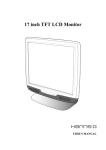
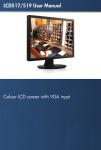
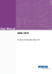
INPUT DIAGRAM
RDP2010UX (Touch screen option)
① Power Switch
② Power Inlet
③ Serial Interface
④ DVI-D Input
⑤ Touch Screen Serial Control (option)
⑥ D-Sub Input
⑦ BNC Input
Revision Status
V2.8
Issued Date
2008-07-31
Page No.
Title
RDP2010UX
6 / 39
(AL20SUX)
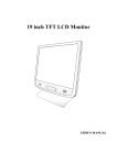
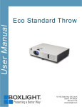
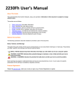
RDP2010UX (CVBS option)
① Power Switch
② Power Inlet
③ Serial Interface
④ DVI-D Input
⑤ Touch Screen Serial Control (option)
⑥ D-Sub Input
⑦ Composite Video Input(BNC)
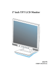
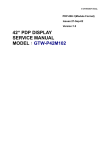
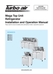
RDP2010UX (MIL MS-3100F10SL-3P option)
Revision Status
V2.8
① Power Switch
② AC MIL power Inlet
③ Serial Interface
④ DVI-D Input
⑤ D-Sub Input
⑥ BNC Input
z
BNC and D-sub input connectable to any source compatible to general CRT monitor
z
Digital input fully compatible to DVI-D Standard of VESA DDWG
z
Chain of Power just one level through power output totally
Issued Date
2008-07-31
Page No.
Title
RDP2010UX
7 / 39
(AL20SUX)
1. TECHNICAL SPECIFICATIONS
1.1
ELECTRO-OPTICAL SPECIFICATIONS
1.1.1
Screen Specifications
1.1.1.1 Panel Technologies
AMLCD (Active Matrix Liquid Crystal Display) technology
Amorphous silicon TFT (Thin Film Transistor) technology
1.1.1.2 Screen Dimensions
Aspect ratio 4:3
Active screen size:
408 (H) x 306 (V) mm (16.06” x 12.04”)
510.5 mm (20.1”) diagonal
1.1.1.3 Display colors
16,777,216 true colors (8-bit), 256 grey scales
1.1.1.4 Resolution
1600 (H) x 1200 (V) pixels
Pixel arrangement: RGB (Red dot, Green dot, Blue dot) Vertical Stripe
Pixel pitch: 0.255 (W) x 0.255 (H) mm
1.1.1.5 Display mode
Normally Black
1.1.2
Optical Characteristics
1.1.2.1 Protective Filter Glass
Clear, Strengthening glass
Anti Reflective Film and Anti-Static Treatment
1.1.2.2 Luminance (Brightness)
280 cd/m² (typ. typical on LCD)
200 cd/m² (max. typical on Protective Filter Glass)
200 cd/m² (max. typical on touch screen)
Dimming Ratio: 1000 to 1
White uniformity: 75% max.
1.1.2.3 Contrast ratio
700 : 1 (typical on LCD)
1.1.2.4 Viewing Angle: At the contrast ratio > 10:1
Horizontal: +/- 89° (typical)
Vertical: +/- 89° (typical)
1.1.2.5 Response time @ 25°C ambient
Tr : (White → Black)
Td : (Black → White)
Tr + Td : 16 ms (typical)
Revision Status
V2.8
Issued Date
2008-07-31
Page No.
Title
RDP2010UX
8 / 39
(AL20SUX)
1.1.3
Input Signal Specifications
RDP2010UX provides maximum four (4) input signal interfaces, 2 x Analog (BNC,D-sub) Input ,1x Digital Input
and 1x Composite video Input.
Standard input resolution is UXGA (1600 x 1200 pixels)
Other resolutions are supported as specified below. No scaling is provided for input signals with resolutions
less than the standard input resolution 1600x 1200 pixels.
Resolution
VGA
SVGA
XGA
SXGA
UXGA(analog)
UXGA(digital)
640 x 480
800 x 600
1024 x 768
1280 x 1024
1600 x 1200
1600 x 1200
Hsync
(KHz)
31.0 - 43.0
35.0 - 53.7
48.4 - 68.3
64.0 – 91.2
75.0 – 93.8
75
Vsync
(Hz)
60.0 - 85.0
56.0 - 85.0
60.0 - 85.0
60.0 - 85.0
60.0 - 75.0
60.0
1.1.3.1 Analog Input
Analog RGB input signal shall be as follows:
Video Signal Level: 0.714 Vp-p nominal
Video Signal Polarity: Positive (Black to White). Polarity is detected automatically.
Both 0 V to +0.714 Vp-p and -0.714 V to 0 Vp-p is allowed.
Video Input Impedance: 75Ω terminated (RGB Video Signal)
Sync: TTL voltage levels, External Separate H & V Sync.
Interlace: Non-interlaced
1.1.3.2 Composite Video Input
Color system : NTSC,PAL,SECAM
Signal Connector : BNC
1.1.3.3 Input Selection
In case multiple input source is connected, input to be displayed can be selected by:
Manual: Operator can select the input manually using control panel.
1.1.4
Controls of the Display
1.1.4.1 Remote Control via serial ports (JH Communication compatible)
There are serial ports on the back side of the RDP2010UX for remote control of the monitor by customer
application.
RS-232/422/485 port: D-Sub, 9p, Female
(for JH protocol)
1.1.4.2 Control via OSD
Control block with the push buttons is available: Menu, Select, ◀ and ▶. Settings are selected by the Menu
that guides you through the OSD menu.
Control block also has ◀ and ▶for dimming brightness.
Control block also has LED indicators, refer to 1.1.5.
Revision Status
V2.8
Issued Date
2008-07-31
Page No.
Title
RDP2010UX
9 / 39
(AL20SUX)
1.1.5
LED Indicator
Fault information in available by LED indicators
Normal : Green indicator
Soft Power Off: Amber indicator
No signal : Amber Blinking (every 1 second) indicator
System Fault : Red indicator
1.1.6
Power Supply Specification
1.1.6.1 Voltage range
Standard :100 –-240Vac(Normal), 47~63Hz,1.7A
Voltage Range : AC 100 - 250V
1.1.6.2 Power consumption
Normal
Max.
(100% Light output)
RDP2010UX
70 W
75W
1.1.6.3 Power variation protection
Unit will not be damaged when Voltage transients remain within value as defined in the applicable voltage
range
1.1.6.4 Over-temperature protection
When the internal temperature gets above than the warning level (65℃), the light output of the backlight is
half. And, LED as red color
When the internal temperature reaches above the critical Value (80℃), the light output of the backlight is
turned off. And, LED as red color
When the internal temperature gets below than the safe level (64℃), the light output of the backlight is
restored. And, LED recovers to green.
1.1.7
Connectors
1.1.7.1 Power connectors
Standard: IEC type connector
MIL MS-3100F10SL-3P (option)
1.1.7.2 Input signal connectors
Analog Input : 5 Coaxial BNC connectors for R, G, B, HS and VS
D-Sub 15pin connector
Digital input : DVI-D connector
Composit video input (option) : BNC connector
1.1.7.3 Interface connectors for remote control
RS-232/422/485 port:
Sub D, 9p, Female
(for JH protocol)
Touch screen serial control (Option): 9p Dsub female
Revision Status
V2.8
Issued Date
2008-07-31
Page No.
Title
RDP2010UX
10 / 39
(AL20SUX)
1.1.8
Connection & PIN Assignment
Power Input / output
● AC 100-250V, 47~63Hz
with double pole / neutral fusing, 250V F3.15AL
● Disconnect power before changing fuse
● Chain thru power output to limit to one level totally
MIL Power Input / output(option)
● MIL MS-3100F10SL-3P
● AC 100-250V, 47~63Hz
1. A: Live(hot) line
2. B: Ground
3. C: Neutral line
Analog Input (BNC)
Analog Input (D-Sub)
●
●
●
●
●
●
R : Analog Red Signal Input (0.7 Vpp, 75 ohm)
G : Analog Green Signal Input (0.7 Vpp, 75 ohm)
B : Analog Blue Signal Input (0.7 Vpp, 75 ohm)
HS : Horizontal Sync Signal Input (TTL)
VS : Vertical Sync Signal Input (TTL)
Connection Type : 5 x BNC
● Connection Type : 15p D-Sub Female (Analog only support)
1.
2.
3.
4.
5.
6.
7.
8.
9.
10.
11.
12.
13.
14.
15.
Video Input (BNC) ( option )
Revision Status
V2.8
Red
Green
Blue
Ground
DDC Ground
Red Ground
Green Ground
Blue Ground
back up
sync Ground
Ground
DDC Data
H sync
V sync
DDC Clock
● CVBS : Composite Video Signal Input
(1.0 Vpp / Sync.negative, 75 ohm)
Issued Date
2008-07-31
Page No.
Title
RDP2010UX
11 / 39
(AL20SUX)
● Connection Type : DVI-D Female (Digital only support)
Digital Input
1.
2.
3.
4.
5.
6.
D-sub
7.
8.
9.
10.
11.
12.
13.
14.
15.
16.
17.
18.
19.
20.
21.
22.
23.
24.
TMDS Data 2TMDS Data 2+
TMDS Data 2/4 Shield
TMDS Data 4TMDS Data 4+
DDC Clock
DDC Data
No Connection
TMDS Data 1TMDS Data 1+
TMDS Data1/3 Shield
TMDS Data 3TMDS Data 3+
+5V power
Ground (Return for +5V)
Hot Plug Detection
TMDS Data 0TMDS Data 0+
TMDS Data 0/5 Shield
TMDS Data 5TMDS Data 5+
TMDS Clock Shield
TMDS Clock+
TMDS Clock-
C1 ~ C5 : No Connection
● Remote In(female)
Serial Interface
1.
2.
3.
4.
5.
6.
7.
8.
9.
Touch Screen Serial Control(option)
No connection
RxD (for RS-232)
TxD (for RS-232)
TxIN_- (for RS-422/485)
RxIN_- (for RS-422/485)
No connection
Ground
TxIN_+ (for RS-422/485)
RxIN_+ (for RS-422/485)
● Touch screen serial control(female)
1. DCD("carrier detect", handshake='0'
(POSITIVE) when controller power on)
2. RXD (serial data from controller to host)
3. TXD (serial data from host to controller)
4. DTR ("data terminal ready", handshake='0'
(POSITIVE) when controller may send )
5. SG (signal ground)
6. DSR ("data set ready", handshake='0'
(POSITIVE) when controller power on)
7. RTS ("ready to send", handshake='0'
(POSITIVE) when controller may send)
8. CTS (used as "ready to receive", handshake='0'
(POSITIVE) when host may send)
9. RI (not used)
Revision Status
V2.8
Issued Date
2008-07-31
Page No.
Title
RDP2010UX
12 / 39
(AL20SUX)
1.2
MECHANICAL SPECIFICATIONS
1.2.1
Dimension and Weight (Rack Mount )
The dimension of the unit is as shown in the table below:
Monitor only
Packing
Height (mm / inch)
399 / 15.70
661/26.02
Width (mm / inch)
482 / 18.97
701/27.60
Depth (mm / inch)
125.5 / 4.94
377/14.84
11 / 24.25
18.5/40.79
Weight (kg / lbs)
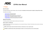
The following figures show a Rack Mount version mechanical dimension. RDP2010UX basically provides three
input connectors and all connectors are located the bottom side of monitor.
< Front View : Unit mm >
< Bottom View >
Revision Status
V2.8
Issued Date
2008-07-31
Page No.
Title
RDP2010UX
13 / 39
(AL20SUX)
< Rear View >
< Side View : Unit mm>
1.2.2
Mounting
The weight for the unit shall not exceed 11 kg (24.25 lbs)
z Fixing: using 4 captive M6 bolts in front bezel
z RDP2010UX can be Standard rack mounted with an optional adapter plate
Revision Status
V2.8
Issued Date
2008-07-31
Page No.
Title
RDP2010UX
14 / 39
(AL20SUX)
1.2.3
Finishing
z
z
Standard Bezel color is Black (Rack Mount Type)
Other bezel colors can be made available on request
1.2.4
Screws/Bolts
z
z
Number of screws to use for maintenance: reduced to minimum
Type of screws requires maximum 3 standard tools
1.2.5
Components
Industrial extended temperature range components are used for cost, maintainability and reproducibility
purposes.
1.2.6
Cooling
The Unit does not need any forced air-cooling
1.3
ENVIRONMENTAL SPECIFICATIONS
1.3.1
Temperature, Vibration, Shock, Humidity(Except touch screen model)
#
1
2
3
4
5
6
7
1.3.2
spec
MIL-STD-810F,Method 501.4
MIL-STD-810F,Method 501.4
MIL-STD-810F,Method 502.4
MIL-STD-810F,Method 502.4
MIL-STD-810F,Method 507.4
MIL-STD-167-1
MIL-STD-810F, Method 516.5
Details
Procedure I
Procedure II
Procedure I
Procedure II
Procedure I
Type I
Procedure I
cycle
7
3
3
1
10
-
EMC(Except touch screen model)
#
1
2
3
4
5
6
7
8
1.3.3
z
Revision Status
V2.8
item
High temp., Storage
High temp., Operating
Low temp., Storage
Low temp., Operating
Humidity
Vibration
Shock
item
Conducted Emission, Power Lead
Conducted Susceptibility, DC and AC Power Leads
Conducted Susceptibility, Bulk Cable Injection
Conducted Susceptibility, damped sinusoidal transients,
cable and power leads
Radiated Emission, Magnetic Field
Radiated Emission, Electric Field
Radiated Susceptibility, Magnetic Field
Radiated Susceptibility, Electric Field
spec
CE 102
CS 101
CS 114
details
10KHz to 10MHz
30Hz to 150KHz
10KHz to 200MHz
CS 116
100KHz to 100MHz
RE 101
RE 102
RS 101
RS 103
30Hz ~ 100KHz
10KHz to 18GHz
30Hz to 100KHz
2MHz to 40GHz
Drip-proof
Front side is drip-proof. Test shall be done when the unit is mounted in a console.
Front bezel: IP64
Issued Date
2008-07-31
Page No.
Title
RDP2010UX
15 / 39
(AL20SUX)
1.4
OHTER SPECIFICATIONS
1.4.1 Maintainability
MTTR (Mean Time Between Repair)
z RDP2010UX is defined as a Line Replaceable Unit (LRU) and the unit is designed to allow for an MTTR
less than 0.5 hour (30 minutes).
z
Use of maintenance equipment
A modular design is taken for the unit. No special tools or equipment are required for maintenance
purpose.
1.4.2 Use of toxic materials
Cold Cathode Fluorescent Lamp (CCFL) in the backlight assemblies contains a small amount of mercury.
The backlight assembly is placed inside of the monitor and is not exposed to user.
1.4.3 Packing
The unit shall be packaged for international transport by air freight in accordance with best practices for insuring
arrival at customer site in an undamaged condition.
Revision Status
V2.8
Issued Date
2008-07-31
Page No.
Title
RDP2010UX
16 / 39
(AL20SUX)
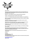
2 User Controls
2.1
Operation
MENU
SELECT
Up/Increase
Down/Decrease
Soft Power Switch
LED indicator
POWER ON AND OFF
Power ON: To turn the display on, press the soft-power switch. The LED indicator will turn green.
Power OFF: To turn the display off, press the soft power switch for 5 seconds. The LED indicator will be
turned Amber color.
DISPLAY DIMMING CONTROLS
This TFT display features a fully dimmable image, which means it is capable of displaying a completely
Black image when the Brightness “◀ and ▶” is pushed fully to counter-clockwise.
LED INDICATOR DIMMING
The LED light intensity is adjusted with the backlight.
HOT KEY
The user can assign various display function as hot keys
Hot Key1 is able to directly source change. Press the “SELECT”.
Hot Key2 is able to directly auto adjustments in Analog. Press the “MENU” and ”SELECT” for 5 seconds.
Hot Key3 is able to directly adjustments Color. Press the “◀” and “▶” for 5 seconds.
Revision Status
V2.8
Issued Date
2008-07-31
Page No.
Title
RDP2010UX
17 / 39
(AL20SUX)
2.2
USER Control Access
1: Press the ”MENU” button. The OSD menu will show all the available functions you can
adjust or control.
2: You can move to the next icon by pressing “◀ and ▶”.
3: Select options within icon menu by pressing “SELECT” button. The select option will turn yellow.
4: Use “◀” or “▶” button to decrease/increase values.
5: Move the selection left or right by using “◀” or “▶” button. The selected option will turn blue bar.
6: You can exit the pressing “MENU”.
2.3
OSD(ON SCREEN DISPLAY) Navigation
The description below is how to operate the control functions via OSD. The following is the initial OSD menu
displayed by pressing “MENU”. It looks like the general computer monitor, so it is more users friendly.
Revision Status
V2.8
Issued Date
2008-07-31
Page No.
Title
RDP2010UX
18 / 39
(AL20SUX)
2.3.1 Adjustment
The “Adjustment” menu is for controlling the brightness, contrast, positions, sharpness, clock and phase.
3.3.1.1 BRIGHTNESS
The function is able the user to adjust brightness for the display, 50 is default value.
“Brightness” adjusts the light output by controlling the opening of Liquid Crystal, it is different from “Dim
Brightness” which is adjusted by controlling the amount of light of backlight directly. But their effects are very
similar. Its adjustment range is -127 to +127. The closer to -127 it is, the darker it is and the closer to +127 it is,
the brighter it is. When one of the submenu of “Adjustment” is selected, the select button push to select it., so
that adjusts the values of the brightness. When the menu button is pushed , going back to the upper menu.
To adjust the brightness is to remap the input data to output data in terms of black and white level. It is to
change the range of data, it means that if the brightness is 127, input data 0 - 255 is remapped to output data
127 – 255, so it looks like brighter. On the other way, if the input data is remapped to 0 – 127, it’ll be darker. It is
to remap the data to LCD panel newly, but it is not to change the real input data. The brightness adjustment
acts on the displayed image of all input data - R, G, and B by the same level.
Revision Status
V2.8
Issued Date
2008-07-31
Page No.
Title
RDP2010UX
19 / 39
(AL20SUX)
3.3.1.2 CONTRAST
The function is able the user to adjust contrast for the display, 50 is default value.
“Contrast” is the submenu of “Adjustment”, which sets up the gain of output video signal to panel. Its
adjustment range is 0 to +100. When one of the submenus of “Adjustment” selected, the select button push to
select it. so that adjust the values of the Contrast. When the menu button pushed, going to the upper menu.
To adjust the contrast is to remap the input data to the output data in terms of white level only. It means that if
the contrast is max. 100, input data over 127 is mapped to 255, so, the depth between black and white is
expanded. On the other way, if it is min. 0, input data 0 – 255 is mapped to 0 – 127, so, the depth is reduced.
The contrast adjustment acts on the displayed image of all input data - R, G, and B by the same level. And it
also controls
the data to panel, but it does not adjust the input signal.
3.3.1.3
H.POSITION
The function is able the user to adjust horizontal position of image
“H-Position” is the submenu of “Adjustment”, which controls the horizontal position of image, Its adjustment
range is 0 to +100 and default is 50. When the H-position of the submenu of “Adjustment” is selected, the
select button push to select it. so that adjust the values of the H-position. When the encoder switch pushed ,
going to the upper menu.
Adjusting the “H-position” shifts the horizontal position of image. If the value of “H-position” is increased or
decreased by pressing “◀ and ▶”, the “H-position” shifts to the right or to the left.
Revision Status
V2.8
Issued Date
2008-07-31
Page No.
Title
RDP2010UX
20 / 39
(AL20SUX)
3.3.1.4 V.POSITION
The function is able the user to adjust vertical position of the display.
“V-Position” is the submenu of “Adjustment”, which controls the vertical position of image, Its adjustment
range is 0 to +100 and default is 50. When the V-position of the submenu of “Analog adjustment” is selected,
the select button push to select it. so that adjust the values of the V-position. When the encoder switch
pushed , going to the upper menu.
Adjusting the V-position shifts the vertical position of image. If the value of “V-position” is increased or
decreased by pressing “◀ and ▶”, the “V-position” shifts the upper or the lower.
3.3.1.5 SHARPNESS
The function is able the user to adjust sharpness for the display
“Sharpness” is for making a clear image. Its adjustment range is 0 to +100. When it is 100, the image is the
Closer to 0
Original
Closer to 100
most clear. When it is closer to 0, the image is blurred. This is not the absolute value on all signals. It may
differ from every signal because the original source quality is very various. If the original signal is good
quality, the image may be looked rather artificially than clearly in max. value 100. In this time, the value
should be adjusted to lower value. If the original source is poor quality, the image becomes clearly more by
adjusting closer to 100. The default value is 50.
Note: This is just for analog signal, and on digital, this function will be disabled.
Revision Status
V2.8
Issued Date
2008-07-31
Page No.
Title
RDP2010UX
21 / 39
(AL20SUX)
3.3.1.6 CLOCK
The function is able the user to adjust the number of sampling clock.
The “Clock” is the menu for the setting of the number of pixels corresponding to the pixel rate of
the
applied analog input signal. It represents the number of sampling clock during one period of horizontal sync
signal.
3.3.1.7 PHASE
The function is able the user to adjust phase of sampling clock
Its range is 0˚ to 360˚ , which is adjusted by 5.625˚ per one step and can be totally adjusted to 64 steps.
This is not represented on OSD by a real phase value, but it is represented by 0 to 100 on OSD.
2.3.2 COLOR ADJ
The “COLORADJ” menu is for controlling the Color Temperature, RGB ADJ and Black.
Revision Status
V2.8
Issued Date
2008-07-31
Page No.
Title
RDP2010UX
22 / 39
(AL20SUX)
3.3.2.1 COLOR TEMPERATURE
The function is able the user to modify the color temperature of the picture for the Display.
Higher temperature : “cooler” picture. Lower temperature : “warmer” picture.
User can select one of 9200K, 6400K, 5600K and User color temperature measured
You can adjust color temperature via the User(RGB)
3.3.2.2 RGB ADJ
The function is able the user to adjust Red, Green and Blue offset for the display
These set up the gain of black level of input video signal to ADC amp (Analog to Digital Converter).
.
Revision Status
V2.8
Issued Date
2008-07-31
Page No.
Title
RDP2010UX
23 / 39
(AL20SUX)
When all white levels are on the points of OSD 50, the amount of color is the same each other.
But, if the level is moved closed to OSD 100, the amount of color to adjust is more, so, the color
to adjust looks like strong. On the other way, if it goes to OSD 0, the amount of color to adjust is
less, so, the color is felt weakly. If the color is changed in brighter level, adjust the white level.
But it also effects on dark level.
3.3.2.3 BLACK LEVEL
The function is able the user to adjust Red, Green and Blue gain for the display
These set up the offset of video signal of ADC amp.
When all black levels are on the points of OSD 50, the amount of color is the same each other. But, if the level
is moved closed to OSD 100, the amount of color to adjust is more, so, the color to adjust looks like strong. On
the other way, if it goes to OSD 0, the amount of color to adjust is less, so, the color is felt weakly. If the color is
changed in darker level, adjust the black level. But it also effects on bright level.
Revision Status
V2.8
Issued Date
2008-07-31
Page No.
Title
RDP2010UX
24 / 39
(AL20SUX)
2.3.3 PIP MENU ( CVBS Model Only )
The “PIP” menu is for controlling PIP(picture in picture) display.
3.3.3.1 PIP On/Off
The function is able the user to enable/disable PIP display.
Analog/Digital RGB
CVBS
PIP is
Main window is displayed on the full screen at the same time as one sub window are displayed in inset window.
Input source of main window is Analog or RGB/Digital RGB input and that of sub window is only CVBS input.
RDP2010 can receive Composite input and it’s also designed to show the images through Composite with
Analog or Digital RGB signal at the same time. There are 2 kinds of size to be adjusted and position can be
adjusted.
Revision Status
V2.8
Issued Date
2008-07-31
Page No.
Title
RDP2010UX
25 / 39
(AL20SUX)
3.3.3.2 PIP Size
In PIP mode, it will change the size of the PIP to ‘Large’ (1/3 screen) or ‘Small’ (1/4 screen).
3.3.3.2 PIP Locate
In PIP mode, it change the position of the PIP to ‘LeftTop’ , ‘RightTop’, ‘RightBottom’ or ‘LeftBottom’.
Revision Status
V2.8
Issued Date
2008-07-31
Page No.
Title
RDP2010UX
26 / 39
(AL20SUX)
2.3.4 SETUP MENU
In this menu, user can set up the setting values.
3.3.3.1 INPUT SELECT
The function is able the user to select one of Analog RGB(D-sub), Digital RGB, BNC,CVBS and S-Video
< RGB(D-sub) / Digital RGB / BNC model >
Revision Status
V2.8
< RGB(D-sub) / Digital RGB / CBVS model >
Issued Date
2008-07-31
Page No.
Title
RDP2010UX
27 / 39
(AL20SUX)
3.3.3.2 COMMUNICATION
“Communication” represents the communication setting between monitors or between the control system and
the monitor
3.3.3.2.1 ID
This assigns the monitor’s number, range one to twelve, in order to identify the monitors, and it must be
unique for distinguishing from each other. And, In the case of chaining several monitors thru communication
port, the ID of monitor to be connected with control system must by One.
Revision Status
V2.8
Issued Date
2008-07-31
Page No.
Title
RDP2010UX
28 / 39
(AL20SUX)
3.3.3.2.2 Baud Rate
“Baud Rate” is the submenu of “Set-Up” which assigns a communication rate, 2400, 4800, 9600, 57600, and
115200 baud rate, that the system can support.
3.3.3.2.3 Communication
This assigns the communication mode. The monitor connecting with the control system is assigned the
RS232 or RS422 and it connecting with other monitor is assigned to the RS485. So, one of three must be
chosen as input communication mode.
Revision Status
V2.8
Issued Date
2008-07-31
Page No.
Title
RDP2010UX
29 / 39
(AL20SUX)
3.3.3.3 OSD SETUP
“OSD Set Up” is the submenu of “Set-Up” which sets up the position of OSD, and OSD Timeout.
3.3.3.3.1 H.Position
This function is able to adjust the horizontal position of OSD.
3.3.3.3.2 V.Position
This function is able to adjust the vertical position of OSD.
3.3.3.3.3 TIME OUT
“OSD Timeout” is the submenu of “OSD Set Up”, which controls the time to display the OSD menu 20, 30,
50, and 100 : When the user don’t touch anything, the OSD menu is disappeared after 20, 30, 50 or 100
seconds, which keeps display OSD.
Revision Status
V2.8
Issued Date
2008-07-31
Page No.
Title
RDP2010UX
30 / 39
(AL20SUX)
3.3.3.3.4 Language
This function is able to choose the OSD language, one of English or Korean.
3.3.3.3.5 Transparency
This function is able to choose the OSD Transparency.
Revision Status
V2.8
Issued Date
2008-07-31
Page No.
Title
RDP2010UX
31 / 39
(AL20SUX)
3.3.3.4 FACTORY RECALL
“Factory Recall” is the menu for restoring to the factory setting values. The settings with which the display
leaves factory are stored in a factory settings storage area on main control board. And the current settings
are stored in a user settings storage area on main control board. At administrator level, the current settings
are replaced by the factory settings. The user settings disappear after changing by the factory settings.
3.3.3.5 INFOMATION
This function describes the Serial Number, S/W version, Temperature, input source, communication Mode
and the light of Backlight.
3.3.3.5.1 Serial NO.
“Serial No.” describes the serial number of monitor. The serial number is unique on every monitor.
3.3.3.5.2 SW ver.
“S/W ver.” describes the version of software installed on monitor.
3.3.3.5.3 Temp.
“Temp. Status” describes the current internal temperature status or the information of the warning level
(65℃), the critical Value (80℃) and the safe level (64℃). See 1.1.6.4.
Revision Status
V2.8
Issued Date
2008-07-31
Page No.
Title
RDP2010UX
32 / 39
(AL20SUX)
3.3.4.5.4 Input
A signal to display now on screen is described.
3.3.4.5.5 Comm.
“Comm.” represents a communication mode.
3.3.4.5.6 Backlight
“Backlight” represents the light of backlight.
Revision Status
V2.8
Issued Date
2008-07-31
Page No.
Title
RDP2010UX
33 / 39
(AL20SUX)
Appendix A: Touch screen driver installation(only for RDP2010TS)
z
How to install the touch screen driver (see the below figure)
1. Dsub (DB9pin) cable connecting between a computer and the Touch screen serial control port
2. Touch screen driver install
3. Touch screen calibration
Notice: If you want to calibrate the touch screen again and touch screen calibration don’t adjust,
You have to fallow the third procedure, touch screen calibration.
.
1. Dsub (DB9pin) cable connecting between a computer and the Touch screen serial
control port for touch screen
Revision Status
V2.8
Issued Date
2008-07-31
Page No.
Title
RDP2010UX
34 / 39
(AL20SUX)
2. Touch screen driver install
Revision Status
V2.8
Issued Date
2008-07-31
Page No.
Title
RDP2010UX
35 / 39
(AL20SUX)
Revision Status
V2.8
Issued Date
2008-07-31
Page No.
Title
RDP2010UX
36 / 39
(AL20SUX)
Revision Status
V2.8
Issued Date
2008-07-31
Page No.
Title
RDP2010UX
37 / 39
(AL20SUX)
Push this point with a finger
or a gloved hand
Revision Status
V2.8
Issued Date
2008-07-31
Page No.
Title
RDP2010UX
38 / 39
(AL20SUX)
3. Touch screen calibration
Revision Status
V2.8
Issued Date
2008-07-31
Page No.
Title
RDP2010UX
39 / 39
(AL20SUX)
Push this point with a
finger or a gloved hand
Revision Status
V2.8
Issued Date
2008-07-31