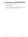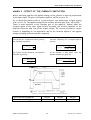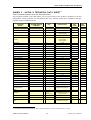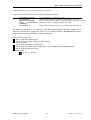
1
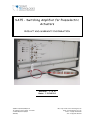
SA75 - Switching Amplifier for Piezoelectric Actuators PRODUCT AND WARRANTY INFORMATION Version : 1.0.0 Date: 11/04/14 CEDRAT TECHNOLOGIES SA 59, Chemin du Vieux Chêne - Inovallée F-38246 MEYLAN CEDEX FRANCE URL: http://www.cedrat-technologies.com Email: [email protected] Phone: +33.(0)4.56.58.04.00 Fax: +33.(0)4.56.58.04.01 SA75 Product and Warranty information CAUTION: READ BEFORE OPENING For safety purposes these instructions must be read before use of this product. This power amplifier is dedicated to multilayers piezoelectric actuators. Only qualified personnel should work on or around this equipment and only after becoming thoroughly familiar with all warnings, safety notices, and procedures contained herein. The successful and safe operation of this equipment is dependent on proper handling, installation and operation. A "qualified person" is one who is familiar with the installation, construction and operation of the equipment and the hazards involved. In addition, he/she has the following qualifications : is trained and authorized to energize, de-energize, clean, and ground equipment in accordance with established practices, is trained in the proper care and use of protective equipment in accordance with established safety practices. CEDRAT TECHNOLOGIES 2 Version 1.0.0 - 11/04/14 SA75 Product and Warranty information TABLE OF CONTENTS 1. 5 2. SYNOPTIC ................................................................... 5 3. GENERAL DESCRIPTION ................................................... 8 4. MAIN VOLTAGE CONNEXIONS .......................................... 13 4.1. Fuses ..................................................................................................................13 5. OPERATING INSTRUCTION FOR THE SWITCHING POWER SUPPLY, AC/DC CONVERTER, (SC75).................................... 14 6. OPERATING INSTRUCTION FOR THE AMPLIFIER (SA75X) ......... 15 7. 8. 9. 6.1. General instructions .......................................................................................15 6.2. Voltage control and current limitation.......................................................18 6.3. Open/closed loop.............................................................................................18 6.4. Using the push–pull mode (2 channels) (only for SA75X-2) .................18 OPERATING INSTRUCTIONS FOR THE OPTIONAL SG75 STRAIN GAUGES CONDITIONER........................................ 20 7.1. General instructions ...................................................................................... 20 7.2. Thermal effect............................................................................................... 20 OPERATING INSTRUCTIONS FOR THE OPTIONAL ECS75 EDDY CURRENT SENSOR CONDITIONER............................... 21 8.1. General instructions .......................................................................................21 8.2. Eddy current displacement sensors ...........................................................21 OPERATING INSTRUCTIONS FOR THE OPTIONAL UC45 DIGITAL CONTROLLER (OPTION) ....................................... 22 9.1. Introduction .................................................................................................... 22 9.2. Terms and definition..................................................................................... 22 9.3. Synoptic............................................................................................................ 23 10. TROUBLE SHOOTING ..................................................... 24 11. WARRANTY CONDITIONS AND EXCEPTIONS......................... 25 12. INSPECTION UPON RECEIPT ............................................ 25 13. AFTER-SALES SERVICE................................................... 26 ANNEX 1 : CONNECTIONS .................................................... 27 CEDRAT TECHNOLOGIES 3 Version 1.0.0 - 11/04/14 SA75 Product and Warranty information Scheme of the cable connection for standard electrical configuration ...... 27 ANNEX 2 : EFFECT OF THE CURRENT LIMITATION ...................... 28 ANNEX 3 : SA75A-X TECHNICAL DATA SHEET ........................... 29 ANNEX 4 : SA75B-X TECHNICAL DATA SHEET ............................ 31 ANNEX 5 : SA75D TECHNICAL DATA SHEET............................... 33 ANNEX 6 : TROUBLE SHOOTING FORM ..................................... 35 CEDRAT TECHNOLOGIES 4 Version 1.0.0 - 11/04/14 SA75 Product and Warranty information 1. SYNOPTIC The switching amplifier SA75 multi-channel consists in a 19 inches casing to the following dimensions: Rack 84F-4U Width : 470 mm Length: 310 mm Height: 200 mm This electronic is a modular one; which means that a rack84F, for instance, may receive two power supply units (SC75) and up to 4 amplification channels (SA75X_Y- X represents A, B, D version and Y represents 1 or 2 channels), as well as sensors conditioning units: Strain gauges sensors conditioner (SG75 unit), Eddy current sensors conditioner (ECS75 unit). And servo controllers: UC45 on the SA75 board, UC65 on specific position. The rear panel includes the main power connection, the ON/OFF switch and the fuses. The front panel includes the connections with actuators, orders, the switches to close the loop (SERVO) and the led indications regarding faults (Cf. Figure 1). The rack can include other boards described in separate documentations. CEDRAT TECHNOLOGIES 5 Version 1.0.0 - 11/04/14 SA75 Product and Warranty information B5 A1 B4 A2 B6 A3 B2 B3 A7 A6 Figure 1 - Front panel of the SA75 power supply Each item is described in the next table. Nota: “X” refers to the “A”, “B” or “D” version of the driving electronics REFERENCE 1st module DESIGNATION Main power supply unit - SC75 A1 Over Voltage – This diode lights when the amplifier detects an overvoltage on the actuator. A2 Over Current – This diode lights when the amplifier detects an overcurrent. A3 Over Temp – This diode lights when the actuator or the amplifier reachs the maximum temp A6 Led power supply presence (green) - Led protect (red) A7 Power On Switch 2nd module Switching amplifier - SA75X B2 Order BNC connector – channel 1 B3 DC offset order potentiometer (10 turn screw)- channel 1 B4 Closed loop selector (SERVO ON / OFF) – channel 1 B5 LEMO connector for piezo actuator – channel 1 B6 LEMO connector for over temperature protection of piezo actuator – channel 1 CEDRAT TECHNOLOGIES 6 Version 1.0.0 - 11/04/14 SA75 Product and Warranty information Nota: If overvoltage, overtemp or overcurrent appear on the SC75 board side, the A6 lights red but no flag appears on A1, A2, A3. WARNING A special care in the use of the LEMO connections should be taken in plugging and unplugging them: you have to pull onto the connector and not the cable. It is strictly forbidden to connect the electrical output channels of several SA75x in parallel. The switching amplifier should be connected to a piezo load before switch on the A7 switch (Power on). If not the power amplifier could be unstable. This product contains components with lethal voltage, it is strictly forbidden for the user to remove the boards from the rack. In the same way, it is strictly forbidden to disconnect the load when electrically powered. CEDRAT TECHNOLOGIES 7 Version 1.0.0 - 11/04/14 SA75 Product and Warranty information 2. GENERAL DESCRIPTION The switching electronic SA75X is dedicated to the supply and control of piezoelectric actuators based on multi-layers piezoelectric ceramics such as APA or PPA from CEDRAT TECHNOLOGIES. The SA75X consists in a power supply with a maximal power given in the attached technical data sheet, including (see Figure 2): A switching power supply (SC75) providing a continuous voltage from the main power (1st module), A switching power amplifier (SA75X) dedicated to capacitive load allowing excitation of piezoelectric actuators between –20 and 150 V (2nd module), A strain gauge conditioner (SG75) allowing to measure the displacement of piezoelectric actuators equipped with gauges (optional module), A servo controller (UC45) allowing to close the loop and to insure a feedback control on the actuator (optional module) Figure 2 - Synoptic of the electronic control of a piezo actuator A switching amplifier is built around PWM technics and a dedicated output filter including inductors and the piezo load. As the piezo load is capacitive, the output PWM is filtered and a continuous output signal is supplied to the piezo load (see Figure 5). CEDRAT TECHNOLOGIES 8 Version 1.0.0 - 11/04/14 SA75 Product and Warranty information Figure 3 - Synoptic of a switching piezoelectric amplifier WARNING The output piezo connexions are floating. This means if the operator wants to measure the output voltage on the load, a differential probe able to withstand more than 250V should be used. If the operator doesn’t take this precaution, damage on the switching amplifier may arise. In the next lines, main performances are explained. Voltage control loop on board: A specific controller is implemented to control the output voltage on the piezoactuators. The controller is tuned with the output load to provide the best performances in regards of the control (speed and accuracy). For the reason, your switching amplifier is tuned with factory settles and the operator cannot change the load without lack of these performances. A range around the initial value is specified corresponding to -25%, +100%. Ex: The switching piezo amplifier is tuned with initial piezo is 30µF, the switching amplifier is stable on the range [20-60]µF. Bandwidth and current limitation: The power switching amplifier is characterized with two specific limitations. The power bandwidth, The signal bandwidth The first one is due to the possibility to the SA75X to provide the necessary current to charge and discharge the piezo load (a capacitance): This is the current or power capability. Following the next formulae: I out C dVout dt The max current is function of your switching power amplifier current range (5, 10 or 20amps). If the commanded signal is high frequency and when the max CEDRAT TECHNOLOGIES 9 Version 1.0.0 - 11/04/14 SA75 Product and Warranty information output current is reached, the output voltage is limited like a slew rate (see Figure 5). Voltage gain versus frequency 180 160 Vo (V peak to peak) 140 120 100 50 µF 100 µF 80 200 µF 60 40 20 0 100 1000 Frequency (Hz) Figure 4 – Power bandwidth description for different loads. The second one is the possibility to drive a piezo when the power bandwidth is not reached (small signal). This parameter is directly linked to the voltage controller performance (see Figure 5). CEDRAT TECHNOLOGIES 10 Version 1.0.0 - 11/04/14 SA75 Product and Warranty information Gain (f) with 30µF 29 27 Gain (dB) 25 23 Gain(f) 21 19 17 15 10 100 1000 10000 Frequency (Hz) Phase (f) with 30µF 0 -20 Phase (°) -40 -60 Phase(f) -80 -100 -120 -140 10 100 1000 10000 Frequency (Hz) Figure 5 – Signal bandwidth description for a 30µF load. CEDRAT TECHNOLOGIES 11 Version 1.0.0 - 11/04/14 SA75 Product and Warranty information Voltage limitation: An onboard input voltage limitation is implemented to avoid some voltage limitations on the piezo load. This limitation doesn’t protect the piezo when over ringing appears on the output voltage (voltage control behavior). Energy recovery on board: The switching amplifier is well suited to drive reactive load. With specific topology, the energy stored in the capacitive load can be transferred in the SC75 power supply. In this case, the switching amplifier doesn’t consume the reactive power but only the active power of the piezoactuators plus the losses in the power switching functions. Ex: A switching power amplifier providing sine signal 10amps at 170ppk to the load (ie 625VA) consumes less than 12.5W (from piezo dielectric losses) plus 30W due to the power components losses. CEDRAT TECHNOLOGIES 12 Version 1.0.0 - 11/04/14 SA75 Product and Warranty information 3. MAIN VOLTAGE CONNEXIONS The switching amplifier is able to be connected on the 110VAC or 230VAC main voltage with any modifications. 3.1. Fuses SC75 (110Vac) fuse 1: 250V 2A T type fuse 2: 250V 2A T type SC75 (230Vac) fuse 1: 250V 2A T type fuse 2: 250V 2A T type Nota : The fuse are reachable in the main voltage plug on the rear face. CEDRAT TECHNOLOGIES 13 Version 1.0.0 - 11/04/14 SA75 Product and Warranty information 4. OPERATING INSTRUCTION FOR THE SWITCHING POWER SUPPLY, AC/DC CONVERTER, (SC75) This module produces from the mains, the regulated DC voltage to the amplifier functioning needs: +200Vdc regulated voltage with 150W max output power. The switch A7 is used to power on and off the power supply and the amplifier. There is a delay of less than two seconds between the activation of the switch and the effective start up of the SC75/SA75. It is possible to neutralise supplied power voltages by using the switch A7. This switch is the easiest way to disable the piezoelectric actuator as soon as required. However, few seconds are necessary to come to a completely discharged actuator. This module is protected against over temperature, over voltage and over current conditions. WARNING It is recommended to keep free space all around the electronic rack while driving in order to make the ventilation easier and to obtain the nominal performance of the driving electronics. Note: Do use the tilt feet for the SA75 rack versions. Do not unplug the SC75 boards when the rack is powered on. This causes large electrical damage and risk for the operator. CEDRAT TECHNOLOGIES 14 Version 1.0.0 - 11/04/14 SA75 Product and Warranty information 5. OPERATING INSTRUCTION FOR THE AMPLIFIER (SA75X) 5.1. General instructions The switching amplifier allows applying to the actuator a signal comparable to the order's one, with a gain of 20 (see Figure 6). offset + Input signal order 20 Voltage amplifier Piezo Actuator Figure 6 - Principle of switching voltage amplifier The order may be applied in two different and complementary manners: Static offset (potentiometer): B3 screw, Dynamic order: B2 connectors. These two signals are added and their sum should fall between –1V and 7.5V. To connect the actuator to the voltage amplifier, the standard cable available is a coaxial LEMO connector in one end and 2 banana 4mm plugs in second end (see Annex 1). A thermal protection of the piezo is implemented when B6 is connected with the temperature sensor embedded on the piezo actuator. When the surface temperature reaches 80°C, the output of the SA75X is switched OFF and only an OFF-ON sequence on A7 switch could rearm the protection to re-initialise the latch. The operator should follow the next sequence to assure a proper use of the switching amplifier. 1. Connect the piezo load on the switching amplifier output. If the load is not connected, the voltage output could be unstable. For piezoactuators with metallic shell, the operator could connect the shell to the earth. 2. Switch on the main selector on the rear panel. The A2, A3, A4 blinks red during few milliseconds and the A6 led should light green. If not, don’t follow the sequence and call your vendor. 3. Verify that B4 is in correct position: Servo Off if the piezo is not coupled with position control loop or Servo On if the piezo is coupled with CEDRAT TECHNOLOGIES 15 Version 1.0.0 - 11/04/14 SA75 Product and Warranty information position control loop. If servo is in On position with no position control loop, a DC signal will be apply on the command corresponding to 5V output. 4. The operator should switch on the A7 switch to power on the switching amplifier with no order through B2 BNC (zero command). With this operation, the Bus voltage is applied on the H Bridge and the amplifier switches. 5. Apply through B2 BNC connector the order. We suggest before sending the final command to valid the voltage output by applying small signals. This suggestion limits some risks on the piezo actuator with a bad order. 6. To switch off the output voltage of the switching amplifier, the operator may only suppress it command (or applying 0V) 7. If maintenance on the piezo actuator or its harness is necessary, the operator should switch off the A7 switch to avoid electrical risk. Nota: A specific sequence is applied on the switching amplifier when the operator switches on the A7 switch. Accordingly, when the SC75 is powered on, the SA75 waits few hundred milliseconds to be operational and able to send the command on the amplifier (See Figure 7). This sequence is necessary to well start the switching amplifier. If the sequence doesn’t work well, the A6 led will light red. In this case, the operator re-initialises the process by switching off the A7 switch followed by switching on. SC75 timing SA75 timing OFF ON OFF ON ORDER ENABLE Order timing Time SC75 start SA75 start Figure 7 – Automatic Ttming during ON switching WARNING When the switching amplifier is commanded to supply the piezo with large current, the operator should valid that the small rise and fall time don’t excite the mechanical resonant frequency of the piezo mechanism. If no protection is taken into account, damages on the MLA can occur with electric and mechanical damages on each part. CEDRAT TECHNOLOGIES 16 Version 1.0.0 - 11/04/14 SA75 Product and Warranty information If the operator wants to increase the length of the harness, the wire section should be above 1.5mm² to be compatible with the large current flow. CEDRAT TECHNOLOGIES 17 Version 1.0.0 - 11/04/14 SA75 Product and Warranty information 5.2. Voltage control and current limitation If the order signal is below –1 V or above 7.5 V, a protective diode and the power amplifier saturation will clamp the signal so that the voltage applied to the actuator stays roughly between –20 V and 150 V. There are some limitations to the constant gain of the amplifier. Indeed, when the variation speed of the input signal (order) increases, the current limitation of the amplifier limits the slew rate of the output voltage. This current limitation varies with the power amplifier (SA75X) version (see annex 3). Nota: the use of a digital input signal (B2) may generate parasitic noise so that an additional filter may be necessary. Over current and over voltage protections are implemented: One over current protection on the output current to avoid damage if large currents are demanded, One over current protection on the H bridge if cross conduction appears, Over voltage protection on the output voltage to avoid damage if large voltage are demanded, For each default, the output of the SA75X is switched OFF and only an OFF-ON sequence on A7 switch could rearm the protection to re-initialise the latch. 5.3. Open/closed loop By default, the open/closed loop selector should be set on the mode open loop (SERVO OFF): in that mode, the amplifier applies a voltage gain of 20 to the input. A displacement sensor, its conditioner and a servo controller will be necessary to use the closed loop (SERVO ON); otherwise the order will be set to zero. 5.4. Using the push–pull mode (2 channels) (only for SA75X-2) For some piezoelectric devices such as the piezoelectric tilts or XY stages, it is necessary to supply two actuators simultaneously. A zero positioning is achieved with an electrical centring. Such a configuration could easily be achieved by using two channels of the SA75, according to the figure shown below. CEDRAT TECHNOLOGIES 18 Version 1.0.0 - 11/04/14 SA75 Product and Warranty information b a n a n a 20 Voltage amplifier p l u g s 20 Piezo actuator 1 + + Piezo actuator 2 Figure 8 – Possible connection for driving piezo actuator in push pull mode. WARNING Do not unplug the SA75 boards when the rack is powered on. This causes large electrical damage and risk for the operator. CEDRAT TECHNOLOGIES 19 Version 1.0.0 - 11/04/14 SA75 Product and Warranty information 6. OPERATING INSTRUCTIONS FOR THE OPTIONAL SG75 STRAIN GAUGES CONDITIONER 6.1. General instructions This module allows reading up to three strain gauges bridges. For each one of them, you can: Read the signal emitted by the conditioner (C2), Adjust the offset (C3). The gain and the offset of the conditioner are adjusted at the factory on a gauge bridge set on the piezoelectric actuator, but only the offset is accessible to the user (C3). If you wish to use the conditioner with another actuator, it may be necessary to modify the gain at the factory. 6.2. Thermal effect The strain gauges solution is the easiest way to operate a piezoelectric actuator in a closed loop. The best accuracy that can be achieved with this sensor is around 0.025%. However, the strain gauges sensor is temperature dependent, so that the offset may vary with temperature. CEDRAT TECHNOLOGIES 20 Version 1.0.0 - 11/04/14 SA75 Product and Warranty information 7. OPERATING INSTRUCTIONS FOR THE OPTIONAL ECS75 EDDY CURRENT SENSOR CONDITIONER 7.1. General instructions The ECS75 card includes up to 2 channels of Eddy Current sensors, which have been calibrated at the factory. Only the offset can externally corrected (F2, F5 trimmers). Figure 9 : - Front panel of the ECS75-2 board 7.2. Eddy current displacement sensors The Eddy Current displacement sensor is a non contact proximity sensor using the eddy current effect generated by the probe in a (preferably) nonferrous material target. The eddy current changes the impedance of the probe, which is read by the conditioner. Although the probe is calibrated with the target, the gain is somewhat dependent on the angle between the probe and the target, the target’s thickness. CEDRAT TECHNOLOGIES 21 Version 1.0.0 - 11/04/14 SA75 Product and Warranty information 8. OPERATING INSTRUCTIONS FOR THE OPTIONAL UC45 DIGITAL CONTROLLER (OPTION) 8.1. Introduction This mezzanine (optional) board UC45 is stackable on the amplifier board and allows the support of two channels. Only one controller is available on the UC45 board, except in the case of the control of XY stage with Eddy Current Sensors. Only the input and output channel selection is configurable on a single board. Two boards with appropriate input/output selection are necessary for a two channel application. The optional board UC45 is available for the boards SA75A-x, SA75B-x and SA75D-x. It performs digital closed loop control with a PID and output filter configuration. The output filter can be either of type notch or lowpass. The optional board UC45 is delivered with a free standard version (latest version downloadable on the web site) of a (Graphical User Interface) GUI software HPDM45. This GUI is a Labview® executable software (the Labview® from National Instruments is not transferred) and provides the following functionalities: Remote control of the drive electronic, Change of the parameters of the controller PID and filter, Order selection between internal (e.g. generated by the GUI), external (analogue order), Reading of the calibration parameters of the sensor using the TEDS functionality. For further details, see the user’s manual for the UC45 controller. Additionally, UC65 controller board can be integrated to improve the sampling rate. 8.2. Terms and definition Resolution: the resolution is the smallest displacement that the sensor (and its conditioning electronic) is able to measure. The resolution is preferably given with a relative value (a percentage of the total range of measurement). Precision error in closed loop: the precision error is the difference between the command and the effective value of the displacement. Several contributors play a role in the precision error (resolution of the sensor, sensitivity to external parameters – ageing, temperature …), corrector error. The precision error is preferably given with a relative value (a percentage of the total displacement). The following table gives the performances of the position sensor Sensor type Resolution Precision error Most contributing factors Strain Gauge (SG) 10-4 10-3 Temperature -5 -4 Eddy Current Sensor 10 10 Temperature ; material (ECS) of the target -5 -5 Capacitive sensor (CS) 10 5.10 Tilt effect between the target and the probe Humidity CEDRAT TECHNOLOGIES 22 Version 1.0.0 - 11/04/14 SA75 Product and Warranty information Table 1 : Performances of the sensors 8.3. Synoptic Figure 10: Synoptic of the UC45 controller CEDRAT TECHNOLOGIES 23 Version 1.0.0 - 11/04/14 SA75 Product and Warranty information 9. TROUBLE SHOOTING PROBLEMS: THE PLUGGED PIEZO ACTUATOR DOES NOT MOVE WHILE THE REAR CONNECTION AND THE A7 ARE SWITCHED ON ACTION POSSIBLE CAUSES Check the led A6 : a) If A6 is off - check the main cable and the fuses at the rear panel b) If A6 is red - - check the connection lines to the piezo actuator / disconnect every LEMO cable. Test the electronics with the unplugged and plugged piezo actuator, as follows - switch A7 off If A6 is green - switch A7 on if the electronics works, - if the electronics doesn’t work, - If A6 is red - Wait for 10 minutes and switch A7 on if the electronics works, if the electronics doesn’t work, PROBLEMS: - misconnection with main cable or burnt fuses The electronics is in protection May be a short circuit through the cable connection or through the piezo actuator occurred an external parasitic noise might have disturbed it a breakdown is certain The electronics was in thermal protection and needed to cool itself down a breakdown is certain INCOHERENT RESPONSE FROM THE ACTUATOR IN OPEN LOOP ACTION Check the output signal (B5) - POSSIBLE CAUSES the DC offset may be wrong If the DC offset is wrong, turn (B3) to settle it* PROBLEMS: INCOHERENT RESPONSE FROM THE ACTUATOR IN CLOSED LOOP ACTION POSSIBLE CAUSES Go back in mode SERVO OFF (B4) and check the the strain gauges offset (C3) may be wrong sensor's response (C2)** * 10 turns potentiometers are used: do not hesitate to rotate the potentiometers and keep attention to the ‘clic’ noise arising at the end of the trimmer range. CEDRAT TECHNOLOGIES 24 Version 1.0.0 - 11/04/14 SA75 Product and Warranty information ** Adjusting the Strain Gauge offset - Apply a command of 0V (by a 50 Ohms BNC connector on B2 for instance), - Check that the voltage output on B5 is nearly zero, - Adjust the potentiometer B3 to get the output B5 near zero, - Measure the output of the Strain Gauge conditioner C2, - Adjust the potentiometer C3, so that the output C2 is 0.38 V One has : Vsg =(SetPointLA + 1) / MaxAmplitudeLA * MaxAmplitudeSG - 0,5 With : MaxAmplitudeLA = 8.5 MaxAmplitudeSG = 7.5 The customer is not entitled to modify the power supply or the switching amplifier. The only manipulations allowed to him are described in the set here above, including the replacement of (the) external fuse(s.). For any other matter or breakdown suspicion, we suggest the customer to contact your local vendor. 10. WARRANTY CONDITIONS AND EXCEPTIONS The equipment is warranted for one year, including parts and labour, and only under standard technical conditions as outlined above and expressly mentioned in the technical data sheet. Repairs will be carried out at CEDRAT TECHNOLOGIES or through your vendor. Shipping, handling and insurance costs to return a part for repair must be paid by the customer. Interventions or attempts to service or repair the SA75 by any unauthorised persons will invalidate this warranty. 11. INSPECTION UPON RECEIPT This product has been inspected and shown to operate correctly at the time of shipment, as verified by the Factory Verification Form that accompanies the power supply Immediately upon receipt of the product, it should be inspected carefully for any signs of damage that may have occurred during shipment. If any damage is found, a claim should be filed with the carrier. The package should also be inspected for completeness according to the enclosed packing list. If an order is incorrect or incomplete, contact your distributor. CEDRAT TECHNOLOGIES 25 Version 1.0.0 - 11/04/14 SA75 Product and Warranty information CEDRAT TECHNOLOGIES recommends the customer to keep the original package for any further carriage of the electronic product. 12. AFTER-SALES SERVICE If a device requires service, please contact CEDRAT TECHNOLOGIES or your local vendor. Please include the device model and serial number in all correspondence with CEDRAT TECHNOLOGIES or your vendor. CEDRAT TECHNOLOGIES 26 Version 1.0.0 - 11/04/14 SA75 Product and Warranty information ANNEX 1 : CONNECTIONS Scheme of the cable connection for standard electrical configuration Banana plugs 4mm (male) Floating Coaxial LEMO connector Banana plugs 4mm (female) Floating Piezo Actuator Electrical cable (1.50 m) for standard connection Earth channel x Amplifier Output Earth Note : the piezo connexions are floatting. Only mechancical shell could be connected to earth CEDRAT TECHNOLOGIES Lemo Driving electronics connection 27 Version 1.0.0 - 11/04/14 SA75 Product and Warranty information ANNEX 2 : EFFECT OF THE CURRENT LIMITATION With a switching amplifier the applied voltage to the actuator is directly proportional to the input signal. The gain of the power amplifier SA75x is set to 20. So, to obtain the whole stroke of a given actuator, one should input a signal varying from –1V to 7.5V. The applied voltage on the actuator will then vary from –20 to 150V. There is some limitation to the constant gain of the amplifier. Indeed, when the variation speed of the input signal (order) increases, the current limitation of the amplifier limits the slew rate of the output voltage. The current provided to a piezo ceramic is depending on its capacitance and on the variation speed of the applied voltage (including internal controller response). The current for a capacitive load is given by the following expression: I piezo C piezo The max frequency for a triangle signal is given by: dv dt f triangle max For a given current limitation, the shortest load time is given by: tload I lim 2 V C piezo If we consider a sine signal, then the maximal frequency is given by: V C piezo f sin max I lim 2 I lim V C piezo 2 Figure A 1 - The current limitation limits the voltage slew rate of the piezo Type of switching amplifier Current limitation (A) per channel CEDRAT TECHNOLOGIES SA75A 5 28 SA75B 10 SA75D 20 Version 1.0.0 - 11/04/14 SA75 Product and Warranty information ANNEX 3 : SA75A-X TECHNICAL DATA SHEET 1 Table of standard properties of use and measurement The properties defined in the table below, are set up according to the technical conditions of use and measurement. These properties are warranted within their variation range and in compliance with the standard technical conditions of use. Properties SA75A Standard technical conditions Unit Nominal values Min. values Max. values Notes - Preliminary data - - Function - Switching power amplifier for piezo actuators - - Max. number of channels - 2 - - Protection - Thermal Current limitation Voltage limitation - - Main voltage VDC 0 / 240 - - Output voltage V -20 / 150 - - Min Output voltage V -20 -21,0 -19,0 Max Output voltage V 150 147,0 153,0 Voltage Gain V/V 20 19,4 20,6 Peak current limitation mA 5000,00 4500,0 5500,0 VA 320,00 275,5 351,9 480 Peak output power Sine output Output load capacitance µF 400 - Control input voltage V -1 ... 7.5 - - Min input voltage V -1 -1,10 -1,00 Max input voltage V 7.5 7,50 7,88 Ripple current % 0,08 - - Total Harmonic distorsion % 2 2,00 4,00 Signal / Noise ratio dB 70,00 63 77 Loaded output bandwidth With 72µF calibrated load Hz 130,03 - - Unloaded output bandwidth With 1.55µF calibrated load Hz 1000,00 800 1100 DC offset setting - 10 turns potentiometer - - Min DC offset V -1,00 -1,02 -0,98 Max DC offset V 7,50 7,35 7,65 PZT connector - LEMO EGH.2B.302.CC - - External Sensor connector - - - - External Control Input - BNC type - - Input impedance k 10,00 - - Back panel interface - DIN41612 type M Male 42 signals pins+ 6 power pins - - Weight kg - - - Dimensions W, L, H mm x mm x mm Compatible with rack 84F 4H, 12F wide, 3H high - - Cooling - Forced air - - Min-Max ambiant Temperature °C 0...40 - - Option - Actuator temp. sensor LEMO EPG-00-302-NLN - - 1 In all CEDRAT TECHNOLOGIES SA documents, the decimal sign is a comma on the line (ISO 31-0:1992). CEDRAT TECHNOLOGIES 29 Version 1.0.0 - 11/04/14 SA75 Product and Warranty information *Bandwidth settled according to your specifications; by default 1 Hz. Properties standard technical conditions of use and measurement Quasistatic excitation Environment Standard main supply Noise measurement conditions Standard load : : : : AC voltage between –20 and 150 V at 1 Hz Ambient temperature (15-25°C) and dry air (Humidity < 50 % rH) Main according to directive HD472; could be adapted to 110 VAC on request Excitation 0.5 Vrms ; reading bandwidth 1 Hz to 1 kHz : Actuator APA from series S or SM : 1.55 µF (load test may be different) Any technical conditions of use, different from those defined above, can lead to temporary or definitive alterations of properties. Thank you to contact CEDRAT TECHNOLOGIES before using actuators under non standard technical conditions. Factory tests carried out Test 1: Load and discharge time Test 2: Linearity output voltage vs. input voltage Extra factory tests Test 3: Gain and linearity in closed loop Test 4: Step response in closed loop (sensor output voltage versus command voltage Test 5: Thermal test at full load Available options [UC ] Servo controller CEDRAT TECHNOLOGIES 30 Version 1.0.0 - 11/04/14 SA75 Product and Warranty information ANNEX 4 : SA75B-X TECHNICAL DATA SHEET Table of standard properties of use and measurement The properties defined in the table below, are set up according to the technical conditions of use and measurement. These properties are warranted within their variation range and in compliance with the standard technical conditions of use. *Bandwidth settled according to your specifications; by default 1 Hz. Properties SA75B Standard technical conditions Nominal values Min. values Max. values - Preliminary data - - Function - Switching power amplifier for piezo actuators - - Max. number of channels - 2 - - Protection - Thermal Current limitation Voltage limitation - - Main voltage VDC 0 / 240 - - Output voltage V -20 / 150 - - Min Output voltage V -20 -21,0 -19,0 Max Output voltage V 150 147,0 153,0 Voltage Gain V/V 20 19,4 20,6 Peak current limitation mA 10000,00 9000,0 11000,0 VA 630,00 551,0 703,8 480 Notes Peak output power Sine output Unit Output load capacitance µF 400 - Control input voltage V -1 ... 7.5 - - Min input voltage V -1 -1,10 -1,00 Max input voltage V 7.5 7,50 7,88 Ripple current % 0,08 - - Total Harmonic distorsion % 2 2,00 4,00 Signal / Noise ratio dB 70,00 63 77 Loaded output bandwidth With 72µF calibrated load Hz 260,06 - - Unloaded output bandwidth With 1.55µF calibrated load Hz 1000,00 800 1100 DC offset setting - 10 turns potentiometer - - Min DC offset V -1,00 -1,02 -0,98 Max DC offset V 7,50 7,35 7,65 PZT connector - LEMO EGH.2B.302.CC - - External Sensor connector - - - - External Control Input - BNC type - - Input impedance k 10,00 - - Back panel interface - DIN41612 type M Male 42 signals pins+ 6 power pins - - Weight kg - - - Dimensions W, L, H mm x mm x mm Compatible with rack 84F 4H, 12F wide, 3H high - - Cooling - Forced air - - Min-Max ambiant Temperature °C 0...40 - - Option - Actuator temp. sensor LEMO EPG-00-302-NLN - - CEDRAT TECHNOLOGIES 31 Version 1.0.0 - 11/04/14 SA75 Product and Warranty information *Bandwidth settled according to your specifications Properties standard technical conditions of use and measurement Quasistatic excitation Environment Standard main supply : AC voltage between –20 and 150 V at 1 Hz : Ambient temperature (15-25°C) and dry air (Humidity < 50 % rH) : Main according to directive HD472; could be adapted to 110 VAC on request measurement : Excitation 0.5 Vrms ; reading bandwidth 1 Hz to 1 kHz Noise conditions Standard load : Actuator APA from series S or SM : 1.55 µF (load test may be different) Any technical conditions of use, different from those defined above, can lead to temporary or definitive alterations of properties. Thank you to contact CEDRAT TECHNOLOGIES before using actuators under non standard technical conditions. Factory tests carried out Test 1: Load and discharge time Test 2: Linearity output voltage vs. input voltage Extra factory tests Test 3: Gain and linearity in closed loop Test 4: Step response in closed loop (sensor output voltage versus command voltage Test 5: Thermal test at full load Available options [ SC ] Servo controller CEDRAT TECHNOLOGIES 32 Version 1.0.0 - 11/04/14 SA75 Product and Warranty information ANNEX 5 : SA75D TECHNICAL DATA SHEET The properties defined in the table below, are set up according to the technical conditions of use and measurement. These properties are warranted within their variation range and in compliance with the standard technical conditions of use. *Bandwidth settled according to your specifications; by default 1 Hz. Properties SA75D Standard technical conditions Unit Nominal values Min. values Max. values Notes - Preliminary data - - Function - Switching power amplifier for piezo actuators - - Max. number of channels - 1 - - Protection - Thermal Current limitation Voltage limitation - - Main voltage VDC 0 / 240 - - Output voltage V -20 / 150 - - Min Output voltage V -20 -21,0 -19,0 Max Output voltage V 150 147,0 153,0 Voltage Gain V/V 20 19,4 20,6 mA 20000,00 18000,0 22000,0 VA 1370,00 1102,0 1407,6 Output load capacitance µF 400 - 480 Control input voltage V -1 ... 7.5 - - Min input voltage V -1 -1,10 -1,00 Max input voltage V 7.5 7,50 7,88 Ripple current % 8 - - Total Harmonic distorsion % 2 2,00 4,00 Signal / Noise ratio dB 70,00 63 77 520,11 - 1100 Peak current limitation Peak output power Sine output Loaded output bandwidth With 72µF calibrated load Hz Unloaded output bandwidth With 1.55µF calibrated load Hz 1000,00 800 DC offset setting - 10 turns potentiometer - - Min DC offset V -1,00 -1,02 -0,98 Max DC offset V 7,50 7,35 7,65 PZT connector - LEMO EGH.2B.302.CC - - External Sensor connector - - - - External Control Input - BNC type - - Input impedance k 10,00 - - - - Back panel interface - DIN41612 type M Male 42 signals pins+ 6 power pins Weight kg - - - Dimensions W, L, H mm x mm x mm Compatible with rack 84F 4H, 12F wide, 3H high - - Cooling - Forced air - - Min-Max ambiant Temperature °C 0...40 - - Actuator temp. sensor LEMO EPG-00-302-NLN - - Option CEDRAT TECHNOLOGIES - 33 Version 1.0.0 - 11/04/14 SA75 Product and Warranty information Properties standard technical conditions of use and measurement Quasistatic excitation Environment Standard main supply : AC voltage between –20 and 150 V at 1 Hz : Ambient temperature (15-25°C) and dry air (Humidity < 50 % rH) : Main according to directive HD472; could be adapted to 110 VAC on request measurement : Excitation 0.5 Vrms ; reading bandwidth 1 Hz to 1 kHz Noise conditions Standard load : Actuator APA from series S or SM : 1.55 µF (load test may be different) Any technical conditions of use, different from those defined above, can lead to temporary or definitive alterations of properties. Thank you to contact CEDRAT TECHNOLOGIES before using actuators under non standard technical conditions. Factory tests carried out Test 1: Load and discharge time Test 2: Linearity output voltage vs. input voltage Extra factory tests Test 3: Gain and linearity in closed loop Test 4: Step response in closed loop (sensor output voltage versus command voltage Test 5: Thermal test at full load Available options [ UC ] Servo controller Properties standard technical conditions of use and measurement Quasistatic excitation Environment Standard main supply Noise measurement conditions Standard load : AC voltage between –20 and 150 V at 1 Hz : Ambient temperature (15-25°C) and dry air (Humidity < 50 % rH) : Main according to directive HD472; could be adapted to 110 VAC on request : Excitation 0.5 Vrms ; reading bandwidth 1 Hz to 1 kHz : Actuator APA from series S or SM : 1.55 µF (load test may be different) Any technical conditions of use, different from those defined above, can lead to temporary or definitive alterations of properties. Thank you to contact CEDRAT TECHNOLOGIES before using actuators under non standard technical conditions. Factory tests carried out Test 1: Load and discharge time Test 2: Linearity output voltage vs. input voltage Extra factory tests Test 3: Gain and linearity in closed loop Test 4: Step response in closed loop (sensor output voltage versus command voltage Test 5: Bode diagram Available options [ UC ] Servo controller CEDRAT TECHNOLOGIES 34 Version 1.0.0 - 11/04/14 SA75 Product and Warranty information ANNEX 6 : TROUBLE SHOOTING FORM In case of trouble or breakdown with the electronic device, this form must be completed by the customer in order to : - Allow Cedrat Technologies to authorise the product return back to the factory, - Help Cedrat Technologies in repairing it. Product: Please give mention here the references and delivery date, History: Please summarise here every action which has been performed with the device since the delivery, Problem description: Please describe here the problems faced with the electronics and which are not described in the paragraph 7, Notations: Please define here the short term used for external devices plugged in the electronics in order to make the writing of “problem identification” easier, Problem identification: Please summarise and describe here, using the “notations”, the operation that could lead to problem identification, Action: Please mention and update here every action undertaken by yourself, by Cedrat Technologies or by your local vendor, Please note that you need to get the authorisation from CEDRAT TECHNOLOGIES before sending back the hardware. CEDRAT TECHNOLOGIES 35 Version 1.0.0 - 11/04/14