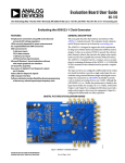
1
Model 8732 User’s Manual
The Picomotor Driver
U.S. Patent No. 5,410,206
CAUTION: Use of controls or adjustments, or performance
of procedures other than those specified herein,
may result in hazardous voltage exposure.
Contents
Is a registered trademark of
New Focus Inc.
800480 Rev. E
2
List of Figures, Tables & Graphs
4
I
User Safety
High Voltage Safety Warning
6
6
II
Quick Start
Unpacking your 8732
Controls and Connections
Setting Up
Adding More Picomotors
7
7
8
12
13
III
Instrument Operation
Modes of Operation
Front Panel Controls
Menu Commands
Rear Panel Connections
Operation
Connecting Picomotors
Powering Up
Instrument Display
Motor/Option Configurations
14
15
17
18
28
30
31
31
32
35
IV
Computer Control
Computer-Control Features
Front-Panel LED’s
IEEE-488 (GPIB) Standard
RS-232 Standard
Response to Commands
Command Syntax
Command Set
Command Set Summary
Picomotor Command Definitions
36
36
36
36
37
38
38
39
40
44
V
Analog and Digital Control
Analog Control
Digital Control
Technical Considerations
68
68
71
78
VI
Connector Information
79
VII Appendices
Appendix A - Keyboard Editor
Appendix B - Table of Commands
91
91
94
AC Operating Voltages
96
Specifications
97
Warranty, Service and Support
98
3
List of Figures
1
Front Panel
8
2
Rear panel inputs and outputs
10
3
The Picomotor is a piezo that turns a screw
14
4
Front Panel
16
5
Menu Tree - Main menu
20-21
6
Menu Tree - Communications menu
22-23
7
Menu Tree - Picotype menu
24-25
8
Menu Tree - Overview
26-27
9
Rear panel inputs and outputs
29
10
Motor / Option configurations
34-35
11
Analog Input lines
69
12
Digital Slot and Connector Lines
72
13
Digital Step and Direction Lines
74
14
Sync Lines
76
15
Sync pulse and screw movement
77
16
Rear panel inputs and outputs
79
17a IEEE-488 (GPIB) Connector
80
17b IEEE-488 (GPIB) Connector Pinout
81
18a RS-232 Connector
82
18b RS-232 Connector Pinout
83
19a 8732 Output and Picomotor Cable Connectors
84
19b 8732 Output and Picomotor Cable Connector Pinouts 85
4
List of Tables
List of Graphs
20a Hand Pad (Control Pad)
86
20b Hand Pad (Control Pad) Pinout
87
21a Control Input
88
21b Control Input Pinout
89
22a Keyboard Connector
90
22b Keyboard Connector Pinout
90
1
Usable connector choice and motor
control combinations
31
2
Digital Slot and Connector Control
73
3
Digital Step and Direction Control
75
1
Pulse frequency as a function of input
voltage
69
5
I
User
Safety
Your safe and effective use of this product is of utmost importance to us at
New Focus. Please read the “High Voltage Safety Warning” before attempting
to operate the Picomotor driver.
High Voltage Safety Warning
Caution: Use of controls or adjustments, or performance of procedures other
than specified herein may result in hazardous voltage exposure.
The Model 8732 is a high-voltage piezoelectric driver system capable of generating dangerous high-voltages. Because of the high-voltage capabilities of
the driver, proper precautions should be taken to avoid electrical shock. All
high-voltage connections are found at the back panel of the driver. High-voltage is present on only one of these connectors at a time, but it can be present
at any time; whether or not the 8732 is being driven by a model 8620 control
pad or an external drive input (analog, digital, or computer control).
Note: Opening the 8732 enclosure will expose voltages up to 200 V DC and
up to 240 V AC. These voltage levels are dangerous. Under most conditions,
the 8732 should not need to be opened. Do not open the 8732 unless instructed to do so by a New Focus representative. Unauthorized opening of the driver
will void the driver warranty.
6
II
Quick Start
This section outlines the quickest path to using your Picomotor driver.
For more detail on how to operate the instrument, refer to Section III. The
instrument is configured at the factory for the line voltage and frequency
appropriate for your country. If you are unsure of how your unit is
configured, check the section on AC Operating Voltages for more details. If
you will be controlling your driver via the RS-232 or IEEE-488 connector, see
section IV.
Unpacking Your 8732
Carefully open the 8732 shipping container and inspect the contents of the
box carefully for any signs of damage. If you notice any signs of damage,
such as dented or scratched covers, broken knobs or switches, etc., please
contact New Focus immediately.
Check the shipping container and its contents carefully for any components
which may be buried in the packing materials. Save the shipping container
so that in the unlikely event that you need to return the unit to New Focus
you can pack it easily and safely.
7
Controls and Connections
Figures 1 and 2 show the front and rear panels of the 8732 with a description
of the controls and the inputs and outputs.
Figure 1
Front Panel
1
2
3
Picomotor Multiaxis Driver
8732
NEW FOCUS, Inc.
4
8
9
7
5
6
8
1
Display: The display shows the current slot and connector addressed
by the driver in the operational mode, and shows the various adjustment parameters for the driver in the menu mode.
2
Addressed Indicator: This LED indicator lights whenever the driver
is addressed externally, showing that communication is taking place.
(See section IV)
3
Remote LED Indicator: This LED indicator lights when the driver
is under remote control, either over the IEEE-488 bus or the RS-232
bus. (See section IV)
4
Power Switch: Turns the driver power on and off.
5
Menu Button: This button switches the driver from normal operational mode to menu mode. (See section III)
6
Select Button: When the driver is in menu mode, pressing the select
button chooses the currently selected menu item for adjustment or
display. (See section III)
7
Display Button: Shifts the display between default slot and connector
descriptions, and user defined descriptions. (See section III)
8
Knob: The control knob allows selection of the various output slots
and connectors in operational mode, and allows selection of the various
menu items available in menu mode. (See section III)
9
Local Button: Pressing this button returns the driver to local control
when the driver is under remote control. (See section III)
9
Figure 2
Rear panel inputs and outputs
1
3
4
2
1
RS232
IEEE 488
2
3
Hand Pad
Keyboard
4
Slot 1
Slot 2
Slot 3
Slot 4
Slot 5
Control Input
5
7
6
10
8
1
IEEE-488 (GPIB) I/O Connector: Allows the connection of a
standard, shielded IEEE-488 cable to the driver, enabling remote control of the driver. (See section III, IV)
2
RS-232 I/O Connector: Allows the connection of a standard 9-pin
RS-232 cable to the driver, enabling remote control of the driver.
(See section III, IV)
3
Slot 1-5: Each slot provides a location for a switch board providing
four 3-axis outputs. The 8732 is configured with two switch boards, providing eight 3-axis outputs. Extra boards can be added providing up to
twenty 3-axis outputs. (See section III)
4
Connector 1-4: Each connector is a six-pin RJ-11 style jack, providing one 3-axis output per jack. (See section III)
5
Power Inlet Module: The power inlet module allows the connection
of input AC power to the driver via the included power cord. The module
also contains the inlet protection fuses. (See section on AC Operating
Voltages)
6
Hand Pad Input: This connector allows the Model 8620 control pad
to be attached to the driver, allowing manual control of the attached
Picomotors. (See section III)
7
Control Input: This connector provides I/O for external digital and
analog control of the driver. (See section III, V)
8
Keyboard I/O: This allows the connection of a standard AT-101 keyboard to the driver. The keyboard can be used to customize the names
displayed for each slot and connector. (See section III)
11
Setting Up
1. Place the driver in the approximate position for use.
2.
Inspect the connectors attached to the various Picomotors that will be
plugged into the driver. The 8732 is configured to accept 6-pin RJ-11
style connectors. These connectors are standard on all of our multiaxis mounts.
NOTE: Our single-axis mounts and micrometer replacement actuators
(MRA’s) use 4-pin RJ-11 connectors. To use MRA’s or single-axis mounts
in the 8732, you will need a Model 8601 Multi-to-single-axis adapter.
12
3.
Plug in the driver, attach the control pad, and plug at least one standard Picomotor into the Slot 1 Connector 1 output jack. Picomotors can
be Standard or Tiny. There is a capacitive difference between the two
types which affects the pulse height that drives them. This in turn
affects the bias voltage that must be applied for normal operation. A
Picomotor can be damaged if it is driven with the wrong
type of drive signal for an extended period of time, so it is
important to ensure that the driver is configured to generate the correct
drive signals. The 8732 is configured at the factory for driving Standard
Picomotors. For Tiny Picomotors, refer to the Picotype Menu under the
Menu Command heading in Section III for instructions on configuring
the 8732 output.
4.
Turn the instrument on and wait for it to go through its self-test
(approximately 5 seconds). The display will first show the message
“New Focus 8732”, then show a message like
“G1.05 M1.05” and finally will switch to the default
connector and slot location (“Slot 1 Conn 1”).
5.
Using the control pad, slide each of the three control buttons forwards
and backwards. When a button is slid forward, its motor should rotate
in a counterclockwise (ccw) direction. When a button is slid backward,
its motor should rotate in a clockwise (cw) direction.
Adding More Picomotors
1. Additional Picomotors can be added simply by plugging them into the
various output connectors provided on the back of the driver.
2.
To use the additional Picomotors, simply rotate the knob (Figure 1,
8 ) located on the front panel until the appropriate slot and connector
number appears on the display. The motors attached to the indicated
jack will then be enabled. Use the control pad or external inputs to
move the currently enabled motor.
13
III
Instrument
Operation
New Focus Standard Picomotor-driven mounts, stages, and micrometer
replacement actuators (MRA’s) can have better than 30 nm resolution (linear
displacement of screw) and allow manual adjustment as well as remote control. The Picomotor — a piezoelectric transducer that turns a screw — doesn’t
exhibit the backlash, creep, or hysteresis problems commonly associated with
piezo-driven actuators. Because the piezo is used only to turn the screw and not
to hold the adjusted position, the set position is maintained even when the
power is off.
Figure 3
The Picomotor is a piezo that turns a screw.
The Patented design of the Picomotor relies on the basic difference between
dynamic and static friction. A graphic example of this is the “table cloth
trick” in which a quick pull of the cloth leaves the vase on the table (low
dynamic friction) while a slow pull of the table cloth ends up pulling the vase
off the table (high static friction, also a big mess!). Our Picomotor uses the
same principle, with two threaded jaws similar to the two halves of a split nut
clamped around a precision 80-pitch screw. One jaw is connected to one end
of a piezoelectric transducer, and the other jaw is connected to the other end
of the transducer. A slow electrical signal applied to the piezo slowly changes
the length, causing the two jaws to slide in opposite directions. This slow slid14
ing motion makes the screw turn (static friction). At the end of the transducer
motion, a fast electrical signal quickly returns the jaws to their starting positions. Because of the screw’s inertia and low dynamic friction, it remains
motionless, holding its position. Changing the order of the fast and slow pulses reverses the direction of rotation of the motor.
Picomotors are very useful in applications requiring a compact, high-resolution positioner. However, keep in mind that the step size of the Picomotor is
not absolutely fixed, and so a Picomotor is not intended to serve as a replacement for a stepper motor. The non-constant step size is the result of the frictional drive mechanism that is used to turn the Picomotor screw. The step
size varies from one Picomotor to another because of variations in the
mechanical parts. In addition, the step size of a particular Picomotor will
decrease as the load the motor pushes is increased. Finally, the Picomotor
step size can change as the motor ages and as the temperature changes.
The Model 8732 driver is a flexible instrument designed to drive up to twenty
3-axis Picomotor mounts or stages (up to 60 individual Picomotors). The
standard 8732 is configured for eight 3-axis mounts (up to 24 individual
Picomotors). The 8732 drives the Picomotors at rates up to 5 rpm, with resolution of <30 nm. (<100 nm for Tiny Picomotors). IEEE-488 and RS-232 interfaces, as well as direct digital inputs allow computer control of the driver and
all motors connected to it.
Modes of Operation
The Picomotor driver has two modes: operational mode and menu mode.
External commands (such as front-panel or GPIB commands) determine
which mode the instrument is in, and which slot and connector are chosen.
Operational Mode
In operational mode, the Picomotor output jacks are enabled and motors can
be driven using the various inputs. Rotating the front panel knob
15
chooses the various output slots and connectors. Pressing the local button
puts the driver in local control if the driver has been in external computer
control. The display button toggles the display between default connector
names (“Slot x Conn y”) and user defined names (“Mirror
1 ”, for example). The menu button switches the driver to menu mode,
allowing access to the various driver configuration menus.
Menu Mode
The purpose of the instrument’s menu mode is to allow the user to adjust the
various operational parameters of the driver. Three controls on the front
panel allow the user to move through the various menus. Pressing the menu
button toggles the driver between operational and menu modes. Once in
menu mode, rotating the knob scrolls between the various menu items. The
select button chooses the selected (indicated by a flashing display) menu
item.
Figure 4
Front Panel
1
2
3
Picomotor Multiaxis Driver
8732
NEW FOCUS, Inc.
16
4
9
7
5
6
8
Front Panel Controls
The 8732 has six front panel controls.
Power Switch:
The power switch
4
turns the AC mains power on.
Menu:
In operational mode, the menu button 5 switches the driver from operational mode to menu mode, enabling reconfiguration of the various driver
parameters. In menu mode, the menu button returns the driver to
operational mode.
Select:
In operational mode, the select button 6 is disabled. In menu mode, the
select button chooses the flashing display item.
Display:
The display button 7 switches the display between default connector names
(“Slot x Conn y”) and user defined connector labels
(“Corner Mount”, for example).
Knob:
In operational mode, rotating the knob 8 selects the desired output slot
and connector. In menu mode, it selects the various menu items by changing which item is flashing.
Local:
Pressing the local button 9 switches the driver from remote computer control mode to local command mode, enabling the user to make changes to
the driver from the various front panel controls.
17
Menu Commands
Two submenus are available from the main menu, the Communications
menu and the Picotype menu. See Figures 5 through 8 for a full description
of the menu system. The circled numbers below refer to Figure 1 (same as
Figure 4).
Communications Menu: The communications menu gives you access to
the RS-232 baud rate and GPIB address.
Changing the RS-232 Baud Rate:
To change the RS-232 baud rate, press the menu button 5 to enter
menu mode. Rotate the knob 8 until “C O M” is selected (indicated
by flashing). Press the select button 6 to enter the communications
menu. Rotate the knob until “RS-232” is flashing. Press the select
button to choose the RS-232 menu. The display will show the current
baud rate (between 300 and 19200). Rotate the knob until the desired
baud rate is chosen. Pressing the select button will set the baud rate and
return the driver to the communications menu. From there the menu
button will take you back to operational mode.
Changing the GPIB Address:
To change the GPIB address, press the menu button 5 to enter menu
mode. Rotate the knob 8 until “C O M” is selected (indicated by
flashing). Press the select button 6 to enter the communications
menu. Rotate the knob until “GPIB” is flashing. Press the select button to choose the GPIB menu. The display will show the current GPIB
address (between 1 and 30). Rotate the knob until the desired address is
chosen. Pressing the select button will set the GPIB address and return
the driver to the communications menu. From there the menu button
will take you back to operational mode.
18
Picotype Menu: The high voltage signals used to drive the Tiny Picomotors
are different from the drive signals for the Standard Picomotors. A
Picomotor can be damaged if it is driven with the wrong type
of signal for an extended period of time, so it is important to ensure
that the driver is configured to generate the correct drive signals. Each channel of every connector has its own configuration. The picotype menu allows
the user to configure the channels of the current connector for Standard or
Tiny Picomotors. All channels of the driver are set for Standard Picomotors at
the factory, so if you are using only Standard Picomotors, no change in the
channel configuration is necessary.
Changing the channel configuration (Standard / Tiny):
To reconfigure the output of a channel, you must first choose a connector, then use the menu system to change the configuration.
Ensure that the driver is in the operational mode. Rotate the knob 8
until the desired slot and connector numbers are displayed. Press the
menu button 5 to enter menu mode. Rotate the knob until “PICO”
is selected (indicated by flashing). Press the select button 6 to enter the
picotype configuration menu. Rotate the knob to choose channel A, B, or
C of the output connector. Press the select button to display the standard/tiny menu. Rotate the knob to choose either
“STANDARD” or “TINY”. Pressing the select button will
save the chosen configuration and return the driver to the picotype
menu, allowing the other channels to be configured.
Menu Tree
Figures 5 through 8 show the menu tree in diagram form. These diagrams
show the various levels of the instrument’s menus, mixing pictorial and written descriptions of how to move around. The icons in the diagrams show the
knobs and buttons required to move through the menus. The circled numbers
found near the icons indicate the number associated with the button or knob
(See Figure 1 or Figure 4).
19
Figure 5
Menu Tree– Main menu
Operational
Mode
SLOT 1 CONN 1
5
or
User Label
6
MENU
Disabled
ENTERS
Menu Mode
8
KNOB
COM
CHOOSES
between menu items.
Chosen item is flashing.
MENU
EXITS
to Operational Mode
Communications Menu:
Choose this menu to access
GPIB and RS-232 menus.
SELECT
ENTERS
Communications
Menu
(Figure 6)
20
SELECT
DISPLAY
Disabled
7
DISPLAY
TOGGLES
between default names
and user names.
PICO
Picotype Menu:
Choose this menu to configure the
driver output for Standard or Tiny Picomotors
(default is Standard Picomotors).
MENU
EXITS
to Operational Mode
SELECT
DISPLAY
ENTERS
Picotype menu
Disabled
(Figure 7)
21
Figure 6
Menu Tree– Communications menu
8
RS-232
EXIT
KNOB
Chooses menu items.
Chosen item is
flashing.
5
MENU
6
EXITS to
Operational Mode
SELECT
EXITS to
Main Menu
7
DISPLAY
Disabled
MENU
SELECT
EXITS to
Operational Mode
KNOB
ENTERS
RS-232 Menu
DISPLAY
Disabled
BAUD RATE [nn]
CHOOSES
RS-232 baud rate
(300 to 19200 baud)
MENU
EXITS to
Operational Mode
22
SELECT
SAVES
RS-232 baud rate
DISPLAY
Disabled
GPIB
MENU
DISPLAY
SELECT
EXITS to
Operation Mode
Disabled
ENTERS
GPIB Menu
KNOB
ADDRESS [nn]
CHOOSES
GPIB address
(1 to 30)
MENU
EXITS to
Operational Mode
SELECT
SAVES
GPIB Address
DISPLAY
Disabled
23
Figure 7
Menu Tree — Picotype menu
8
EXIT
KNOB
CHOOSES
the menu items.
Chosen item is flashing
5
MENU
6
EXITS to
Operational Mode
24
SELECT
EXITS to
Main Menu
7
DISPLAY
Disabled
A:S
or
T
B:S
MENU
T
SELECT
EXITS to
Operational Mode
KNOB
or
ENTERS
Standard/Tiny Menu
C:S
or
T
DISPLAY
Disabled
STANDARD / TINY
CHOOSES
between
Standard and
Tiny Picotypes
MENU
EXITS to
Operational Mode
Does not save
SELECT
SAVES
Picotype Selection
DISPLAY
Disabled
25
Figure 8
Operational Mode
Menu Tree
Display Button
User Label
Slot Conn
Menu Button
Menu Mode
COM PICO
COM PICO
EXIT RS232 GPIB
19200
Knob changes choice
Select saves it
Choices are:
19200
9600
4800
2400
1200
300
all are 8 bits, 1 stop, no parity
26
1
Knob changes choice
Select saves it
Choices are:
1
.
.
30
Menu button toggles between
operational mode and menu mode.
Select takes you through menus
and saves parameters.
Knob changes selection.
EXIT A:S B:T C:S
Standard
Tiny
Knob changes choice
Select saves it
Choices are:
Standard
Tiny
...
Standard
...
27
Rear Panel Connections
The 8732 has 7 rear panel connections. See section VI for pin descriptions.
IEEE-488 (GPIB) I/O Connector:
The IEEE-488 connector 1 is a standard female 24-pin GPIB style connector.
To use the GPIB port, attach a standard, shielded GPIB cable to the connector.
See section IV for further information about computer control.
RS-232 I/O Connector:
The RS-232 connector 2 is a standard female 9-pin D-connector. To use the
RS-232 port, attach a standard, shielded male RS-232 cable to the connector.
See section IV for further information about computer control.
Slot 1-5:
Slots 1 through 5 3 are the output slots. The slots are numbered 1-5 from
left to right when viewed from the back of the driver. Each slot can hold a
switch board which has four 3-axis outputs. The 8732 comes factory configured with two switch boards, providing eight 3-axis outputs. Extra boards can
be added to provide a maximum of twenty 3-axis outputs (sixty individual
Picomotors).
Connector 1-4:
The output connectors 4 are standard 6-pin RJ-11 style telephone jacks. The
individual connectors are numbered 1 through 4 from top to bottom.
Power Inlet Module:
The power inlet module 5 accepts the universal power cord. The bottom of
the module contains two fuses. For more information about the inlet power
requirements and fuses, see the section on AC Operating Voltages.
Hand Pad:
The hand pad input 6 is a standard female 15-pin D-connector and accepts
the inputs from the Model 8620 Control Pad.
28
Control Input:
The control input connector 7 is a standard female 25-pin D-connector. It
accepts both TTL-level digital inputs and analog control signal inputs. For
more information about analog and digital inputs, see section V.
Figure 9
Rear panel inputs and outputs
1
3
4
2
1
RS232
IEEE 488
2
3
Hand Pad
Keyboard
4
Slot 1
Slot 2
Slot 3
Slot 4
Slot 5
Control Input
5
7
6
8
Keyboard:
The keyboard input connector 8 is a standard female 5-pin DIN computer
keyboard connector. This connector is configured to accept the inputs from a
standard AT-101 computer keyboard and allows the user to change the default
display names of the various slots and connectors. For more information
about changing the display, see the discussion on the instrument display later
in this section.
29
Operation
The model 8732 provides many options for driving Picomotors. The instrument can drive up to three motors simultaneously from any one of the up to
twenty 3-axis connectors.
The motor speed can be controlled in four ways:
1. The 8620 Control Pad.
2. Analog voltages applied to the Control Input or Hand Pad Input.
3. Digital TTL level “step” and “direction” signals applied to the
Control Input.
4. Remote computer control over the GPIB or RS-232 busses.
The connector being driven can be chosen in three ways:
1. Turning the knob on the front panel.
2. Digital TTL level “slot” and “conn” signals applied to the
Control Input.
3. Remote computer control over the GPIB or RS-232 busses.
The usable combinations of method of connector choice and method of
motor movement are shown in the table below.
For example, it’s possible to control the speed of the motors with an analog
signal while selecting the connector with TTL digital signals but not while
selecting the connector over the GPIB or RS-232 busses.
30
Table 1
Usable connector choice and motor control combinations
Motor
Control
Control Pad
Analog Input
Digital Input
GPIB/RS-232
Connector Choice
Digital GPIB /
Front
Panel
Yes
Yes
Yes
No
Input
Yes
Yes
Yes
No
RS-232
No
No
No
Yes
Connecting Picomotors
Multi-axis mounts can be connected directly to the output jacks, and singleaxis components such as MRA’s can be connected via a Model 8601 Multi-tosingle-axis adapter. See Figure 10 for some examples. The output display can
be configured to show either default names (“Slot x Conn y”) or
to show user defined labels
Powering Up
Before powering up the 8732 Picomotor driver for the first time, read the
instructions in the section on AC Operating Voltages. Check to be sure that
your unit is set up for the AC line voltage at your location. Attach the control
pad to the 15-pin D-Sub connector on the back panel. Attach picomotors to
the various connectors on the rear panel.
Note: Be sure that the connectors on the Picomotors match the jacks on the
driver. Multi-axis Picomotors use 6-pin RJ-11 style connectors, and singleaxis Picomotors such as MRA’s use 4-pin RJ-11 style connectors. The 8732
output ports are 6-pin RJ-11 jacks. To use single-axis devices, obtain an 8601
Multi-to-single-axis adapter and attach it between the driver and the motor.
31
Turn the unit on using the front panel power switch. The 8732 first performs
tests on the various subsystems in the instrument. If all the subsystems are
working properly, the display will read “New Focus 8732”
then show the firmware version numbers (something like
“G1.05 M1.05”) followed by the default output port name
“Slot 1 Conn 1”. At this time the instrument is ready to drive
motors. To drive an individual motor, rotate the front panel knob until the
appropriate output jack is selected. Pushing slider A, B, or C on the control
pad will drive the correspondingly labeled motor on the multi-axis mount or
8601 adapter. To drive multiple motors simultaneously, push the appropriate
sliders at the same time.
Instrument Display
The instrument display consists of a 16-character alphanumeric display and
two LED indicators. The format of the alphanumeric display is dependent on
the instrument’s operating mode. The LED indicators at the right-hand side
of the display show the communications state of the driver. The Addressed
indicator flashes each time the instrument is addressed by an external computer. This indicator may flash very rapidly (appearing to be on continuously). The Remote indicator is lighted when the instrument is under remote
computer control. To switch the driver back to local control, press the Local
button on the front panel.
Default Display
The default output connector names are “Slot x Conn y”,
where x is 1 to 5, and y is 1 to 4. The slot numbers are shown in Figures
2 and 4, and are numbered 1 through 5 from left to right (as seen facing
the back of the 8732). The connectors are numbered 1 through 4 from
top to bottom.
32
User Display
You may choose to give your connectors labels that are meaningful to
your particular setup. To enter your own labels, attach a standard
AT-101 computer keyboard to the back panel connector provided. Rotate
the front panel knob until the slot and connector to be labeled is displayed. Begin typing in the new name (up to 16 characters). To store the
name, press the ESC key on the keyboard, or push the front panel LOCAL
button. The display will return to default display. To toggle between the
default display and your personal labels, push the front panel display
button. See Appendix A for a complete discussion of the keyboard editor.
33
Figure 10
Motor/Option Configurations
3-Axis Mirror Mount
Model 8809
RS232
IEEE 488
Hand Pad
Keyboard
Slot 1
Control Input
Picomotor Control Pad
Model 8620
34
Slot 2
Slot 3
Slot 4
Slot 5
Motor/Option Configurations
This diagram shows some of the various options and motor attachments possible with the
8732. Additional switch boards can be added to the 8732 to increase the total number of
Picomotors that can be driven.
Multi-Stage Axis
Model 8082
Rotary Stage
Model 8401
Micrometer-Replacement
Actuator
Model 8302
Multi-to-Single Axis
Adaptor
Model 8601
Tiny
Micrometer-Replacement
Actuator
Model 8351
35
IV
Computer
Control
The Model 8732 Picomotor Driver can be operated remotely by either its
IEEE-488 (GPIB) or RS-232 (Serial) interface. Most computers have RS-232
interfaces built in. In order to use the GPIB interface you’ll need to buy a
special card or interface box. The GPIB interface is many times faster than
the RS-232 interface and can be used to talk to up to 30 instruments at the
same time. RS-232 is limited to controlling one instrument at a time. Before
attempting to communicate with the instrument you must set the device
address or the baud rate via the front panel menu by following the instructions in Section III.
Upon receiving a computer command, the front panel functions are locked
out. Use the Local front panel button to re-enable the front panel. The slot
and connector remain the same as they were under remote computer control.
Computer-Control Features
The computer commands allow you to perform all front panel operations as
well as access several functions that can only be reached through computer
control.
Front-Panel LED’s
Two LED’s on the front panel pertain to remote operation of the Picomotor
Driver. The Remote LED lights when an interface command is received to
show that the front panel buttons are locked out. The Addressed LED flashes
when data is sent or received through the remote interfaces.
IEEE-488 (GPIB) Standard
GPIB stands for General Purpose Interface Bus. It is also known as the IEEE488 standard. GPIB is a standard protocol used by personal computers to
communicate with laboratory instruments. Several manufacturers make
printed circuit board “cards” that plug into your computer and allow it to
speak on the GPIB. You will have to learn from the manufacturer of your
36
GPIB card how to configure it to talk to an instrument at a given address and
how to issue commands to it from your favorite programming language. In
QuickBasic, for example, commands are sent to the 8732 through the GPIB
functions IBWRT and IBRD. IBWRT sends an instruction to the 8732. IBRD
reads back the response to the command. Examples of the 8732’s responses are
“OK” or “Unknown Command”.
RS-232 Standard
RS-232 is a widely available standard for communication via your computer’s serial port. You might want to use RS-232 to save yourself the expense of
a GPIB card. There are two drawbacks to RS-232. One is you can only talk to
one instrument at a time. The other is that RS-232 is many times slower than
GPIB. You will need to know how to send commands to your computer’s RS232 serial port. Any terminal emulation program will let you interactively
send and receive via the serial port.
RS-232 ports can be configured for operation in DTE or DCE mode. The
Picomotor driver is configured as a DTE port. This means that the Picomotor
driver receives data on pin 3 and transmits data on pin 2. This allows it to be
directly connected to a PC’s COM port.
RS-232 communications may be performed at 300, 1200, 2400, 4800, 9600,
or 19200 baud. The data format is 8 bits, no parity with 1 stop bit.
For RS-232 operations use @ to get attention before starting command entry,
and end the command with a carriage return (<CR>). “@” is the attention
signal which must be the first character of each command string. RS-232
commands are identical to the GPIB commands. RS-232 commands are sent
as a continuous string. For example: “@pulse:freq 1.2 kHz <CR>”.
37
Response to Commands
The driver does not echo the command or the query.
If you send a command, the driver will return one of the following responses:
“OK” if the command was properly executed.
“Out of Range” if a parameter is outside its allowed range.
“Unknown Command” if the command was not recognized.
If you send a query, the driver will return:
The value you requested or
“Unknown Command” if the command was not recognized.
For example: if you send “source:puls:freq?”, you get back something like
“1500 Hz”
With RS-232 communications, the response is sent immediately and you
may process or ignore the data. With IEEE-488 communications, the
response is loaded into the output buffer. You may read it with the appropriate command or else ignore it.
Multiple Commands per Line
Multiple commands may be sent on a single line. The commands should be
separated by a semi-colon (;). The maximum line length is 256 characters.
The response from a sequence of commands is that of the last one as each
succeeding command response overwrites the last
Command Syntax
In the list that follows, we use the following conventions to describe the interface commands. The uppercase parts of commands are mandatory, while the
lowercase parts of the commands are optional. A choice of parameters is
38
indicated by enclosing a command list in parentheses, while the individual
options are separated by vertical bars.
All commands are case insensitive. The command preambles are either
of the characters “*” and “:” and are optional. The character “;” is the
command separator. <wsp> is any combination of white spaces (spaces or
TAB’s). Remember to begin everything with an “@” if you are using RS-232.
The command is not parsed until a carriage return is received (RS-232)
or a hardware EOI is detected (GPIB). Numbers may contain at most 15
characters. Commands that expect integer values will truncate after any
decimal point in the input, so “11.56” is truncated to “11”.
Command Set
The command set is detailed in the following pages. For each command
the syntax is shown followed by an explanation of any parameters.
Finally an example or two is added to give the flavor of how you might use
the command.
The examples show the command or query and the response from the
instrument. For instance, the example for the identification query appears
as follows:
IDN?
-> NewFocus 8732 M1.00, G1.00
The example demonstrates that the string IDN? is sent to the instrument
over RS-232 or GPIB. The arrow symbol (-->) indicates the response from
the instrument.
39
Command Set
Summary
Standard Commands
*IDN?
Source Commands
:SOURce:PULSe:COUNt <value>
:SOURce:PULSe:PERiod <value[S|MS]|MAX|MIN>
:SOURce:PULSe:PERiod? [MAX|MIN]
:SOURce:PULSe:FREQuency <value[HZ|KHZ]|MAX|MIN>
:SOURce:PULSe:FREQuency? [MAX|MIN]
:SOURce:DIRection CW|CCW
:SOURce:DIRection?
Instrument Commands
:INSTrument:CATalog? <number>
:INSTrument:CATalog:FULL? <number>
:INSTrument:DEFine <”name”>,<number>
:INSTrument:DELete[:NAMe] <”name”>
:INSTrument:DELete:ALL
:INSTrument:[NSELect] <number>
:INSTrument:[NSELect]?
:INSTrument:SEL <”name”>
:INSTrument:SEL?
:INSTrument:STATe 0|1|OFF|ON
:INSTrument:STATe?
40
queries instrument identification
sends out specific number of pulses
sets period of pulsed waveform
queries current period
sets pulse frequency
queries current pulse frequency
sets direction
queries current direction
lists logical names
lists logical names and numbers
associates logical name w/number
disassociates logical name
disassociates all logical names
selects channel by logical number
queries current logical number
selects channel by logical name
queries current logical name
turns current channel on or off
queries if current channel is on or off
41
System Commands
:SYSTem:CTYPe? <slot>
:SYSTem:DEFine <”name”>,<STD|TINY>
:SYSTem:DEFine? <”name”>
:SYSTem:NDEFine <number>,<STD|TINY>
:SYSTem:NDEFine? <number>
For the logical number of a channel, use a three digit number XYZ where:
X = slot number [1-5]
Y = connector number [1-4]
Z = 1 for channel A, 2 for channel B and 3 for channel C
A two digit logical number of XY where:
X = slot number [1-5]
Y = connector number [1-4]
is valid for INSTrument:DEFine and INSTrument:CATalog and defines a
connector, allowing you to set and read the front panel user label.
42
identifies card in slot
0 - No card
1 - SwitchCard
2-255 - Reserved
defines Standard or Tiny Picomotor using logical name of channel
queries type of Picomotor using logical name of channel
0 - Standard
1 - Tiny
2-255 - Reserved
defines Standard or Tiny Picomotor using logical number of channel
queries type of Picomotor using logical number of channel
0 - Standard
1 - Tiny
2-255 - Reserved
43
Go to Local
Command
*GTL
Query
None
Description
Takes the 8732 back to Local control just as if you had hit the front panel
LOCAL button.
The current slot and connector remain the same. All pulsing is terminated.
Explanation
Example
As the Slot and Connector are not changed as you exit from remote, this is a
convenient way to use computer control to choose the Slot and Connector
and then exit to Local to use either the hand-pad or some external analog or
digital TTL control circuitry.
The 8732 is pulsing on SLOT2 CONN2 under REMOTE control.
*GTL
—> OK
(Note: you can read the response
without reentering REMOTE)
The 8732 is now in LOCAL and still at SLOT2 CONN2. The handpad and
digital TTL control now work.
44
Picomotor
Command
Definitions
Identification Query
Command
Query
None
*IDN?
Description
Queries Identification
Explanation
Returns the following string identifying the instrument:
New Focus 8732 M:SoftwareRev G:SoftwareRev
The M and G Software Revision numbers show the current software revisions
for the two microprocessors and should be the same number.
Example
Request the identity of the 8732.
*IDN?
->New Focus 8732 M:1.05 G1.05
45
Operation Complete
Command
Query
Not implemented
*OPC?
Description
The operation complete query returns an ASCII “1” when all pending
operations have been finished. An ASCII “0” is returned if any operation
is pending.
Explanation
The only operations that are considered pending for the 8732 are fixed
numbers of pulses. Therefore if any of the three channels is in the process
of sending out a fixed number of pulses, the operation complete query will
return a “0”.
This is different from the :INST:STATE? query in two ways.
1. :INST:STATE? returns the status of only the current channel
2. :INST:STATE? returns a “1” if the channel is doing a fixed
number of pulses or has simply been turned on and is pulsing
continuously. *OPC? will return a “0” while any of the channels
is doing a fixed number of pulses but pulsing continuously is
considered to be a completed operation so if all three channels
were pulsing continuously, *OPC? would return a “1”.
46
Example 1
Use *OPC? to detect end of pulse sequence
:SOUR:PULS:COUNT 1000
—> OK
. . . . pulsing begins
*OPC?
—> 0
(Operation not complete)
INST:STATE?
(Channel is on)
. . . . pulsing completes
—> 1
*OPC?
—> 1
(Operation is complete)
:INST:STATE?
—> 0
Example 2
(Channel is off)
*OPC? considers continuous pulsing to be a completed operation
:INST:STATE ON
—> OK
. . . . pulsing begins
*OPC?
—> 1
(Operation is complete)
:INST:STATE?
—> 1
(Channel is on)
47
Reset Command
Command
*RST
Query
None
Description
The Reset command performs a device reset, placing the 8732
in a known state.
Explanation
The reset conditions are as follows:
1. Channel 111 is the current channel
2. All channels off
3. All channel directions set to OUT
4. OPC? status cleared (all operations complete)
Example
The current channel is 221. The front panel reads SLOT2 CONN2.
All three channels are pulsing.
*RST
—> OK
All pulsing stops. The front panel now reads SLOT1 CONN1 as the current
channel is now 111.
48
Self-Test Query
Command
Query
Description
Explanation
Example 1
NONE
*TST?
The self-test query causes an internal self-test and responds with the
results of that test. Nothing about the instrument state is modified because
of this command.
A successful test returns a “0”. Right now all tests are successful. In the
future unsuccessful tests will return information about the origin of the
failure. This command is included now for compatibility with standard
initialization routines.
8732 is in perfect working order
*TST?
—> 0
Example 2
8732 has been run over by a truck, nothing works but somehow it is
still able to communicate.
*TST?
—> 0
49
Source a fixed number of pulses
Command
Query
:SOURce:PULSe:COUNt<wsp><NumericValue>
None
Description
Sends a number of pulses out the current channel.
Explanation
Exactly the described number of pulses are sent out.
The channel and the direction are set elsewhere.
Maximum number of pulses is 65535.
Minimum number of pulses is 0.
The 8732 will send the requested number of pulses at the current
frequency immediately upon receiving the command.
Example
Send five pulses to the currently selected channel.
:SOUR:PULS:COUN 5
—> OK
50
Source pulses period
Command
Query
:SOURce:PULSe:PERiod<wsp><value[s|ms]|MAX|MIN>
:SOURce:PULSe:PERiod?<wsp>[<MAX|MIN>]
Description
Sets or queries the period of the pulsed waveform (default seconds).
Explanation
Minimum period is approximately 670 µs.
Maximum period is 44 seconds.
The allowed periods are integer multiples of the minimum:
Min, Min*2, Min*3, .... Min*65535
The actual period will be the nearest allowed period to the requested period.
(Examples are on the next page)
51
Example 1
What is the minimum period?
:SOUR:PULS:PER? MIN
—> .00067 s
(Allowed periods are 670 us, 1.34 ms, 2.01 ms, 2.68 ms, 3.35 ms . . .)
Example 2
Request a period that is not exactly an allowed period.
:SOUR:PULS:PER 1.400ms
—> OK
:SOUR:PULS:PER?
—> .00133 s
(Actual period is closest allowed period)
Example 3
Request the minimum period.
:SOUR:PULS:PER MIN
—> OK
:SOUR:PULS:PER?
—> .00067 s
(Actual period is the minimum period)
52
Source pulses by frequency
Command
Query
:SOURce:PULSe:FREQuency<wsp><value[Hz|KHz]|MAX|MIN>
:SOURce:PULSe:FREQuency?<wsp>[MAX|MIN]
Description
Sets or queries the pulse frequency (default Hz).
Explanation
Maximum frequency is 1.5 kHz.
Minimum frequency is .023 Hz.
Allowed frequencies are integer dividends of the maximum:
MaxFrequency, MaxFrequency/2, MaxFrequency/3,
... MaxFrequency/65535
The actual frequency used will be the closest allowed frequency to the
requested one.
The query will return the actual frequency used.
(Examples are continued on the next page)
53
Example 1
What is the maximum frequency?
:SOUR:PULS:FREQ? MAX
—> 1500 Hz
(Allowed frequencies are 1500, 750, 500, 375, 300, ...)
Example 2
Request a frequency that is not exactly an allowed frequency.
:SOUR:PULS:FREQ 700
—> OK
:SOUR:PULS:FREQ?
—> 750 Hz
(Actual frequency is the nearest allowed one)
Example 3
Request the maximum frequency.
:SOUR:PULS:FREQ MAX
—> OK
SOUR:PULS:FREQ?
—> 1500 Hz
(Actual frequency is maximum frequency)
54
Set direction of motion
Command
Query
:SOURce:DIRection<wsp>IN|OUT|CW|CCW>
:SOURce:DIRection?
Description
Sets or queries the Picomotor direction.
Explanation
CW is for clockwise.
CCW is for counterclockwise.
The screw is right-hand threaded, so CW rotation moves the screw IN
and CCW rotation moves the screw OUT.
Reponses to the query are CW and CCW only.
Example 1
Move the screw into the mount.
:SOUR:DIR CW
—> OK
:SOUR:DIR?
—> CW
Example 2
Move the screw out of the mount.
:SOUR:DIR OUT
—> OK
:SOUR:DIR?
—> CCW
55
List logical names
Command
Query
None
:INSTrument:CATalog?<wsp><number>
Description
Lists logical names
Explanation
Lists all the logical names associated with the indicated channel on installed
switch cards. No channel numbers are given.
Example
List the logical names for two channels and a connector.
Assume a switch card is installed in Slot 1 and that Connector 1 has been
assigned the name “LensSet” while its channel A has been assigned the
name “FocusLens” and its channel B has been assigned the name
“TiltLens”.
INST:CAT? 111
—> FocusLens, LensSet_A,
INST:CAT? 112
—> TiltLens, LensSet_B,
INST:CAT? 11
—> LensSet
Note: “LensSet” is the name that appears on the front panel if
Slot 1, Connector 1 has been chosen and the User Display is active.
56
List logical names and number
Command
Query
None
:INSTrument:CATalog:FULL?<wsp><number>
Description
Lists logical names and numbers for installed cards
Explanation
Returns a list of device numbers and associated logical names
for all the slots that have switch cards.
Example
List the logical names and logical number for two channels and a connector.
Assume a switch card is installed in Slot 1 and that Connector 1 has been
assigned the name “LensSet” while its channel A has been assigned the name
“FocusLens” and its channel B has been assigned the name “TiltLens”.
INST:CAT:Full? 111
—> FocusLens, LensSet_A, 111
INST:CAT:Full? 112
—> TiltLens, LensSet_B, 112
INST:CAT:Full? 11
—> LensSet,11
Note: “LensSet” is the name that appears on the front panel if
Slot 1, Connector 1 has been chosen and the User Display is active.
57
Assign logical name to channel or connector
Command
Query
:INSTrument:DEFine<wsp><”name”>,<number>
None
Description
Assigns a logical name to a logical number.
Explanation
Every channel (which corresponds to a Picomotor axis) and connector can be
assigned a logical name that is more meaningful than the standard logical
number.
A logical number that includes the slot, connector and channel number
assigns the logical name to the channel.
This name can be up to 21 characters long and can be used to select the
channel just as you would with the logical numbers.
A logical number that only includes the slot and connector numbers assigns
the logical name to the connector.
These names can be only 16 characters long and will appear on the front
panel of the instrument if the user display is selected.
The 8732 recognizes some associated logical names which are the connector
name with a _A, _B and _C appended. These can be used anywhere a logical
name can be used.
Note: This process works in reverse also. A name assigned to a connector
from a keyboard plugged into the backpanel can be used in your program
with the _A, _B or _C appended to access individual channels.
Examples
58
See next page.
Example
Assign the logical name “FocusLens” to Slot 1 Connector 1 Channel A.
Assign the logical name “TiltLens” to Slot 1 Connector 1 Channel B.
No logical name will be assigned to Channel C.
INST:DEF “FocusLens”,111
—> OK
INST:DEF “TiltLens”,112
—> OK
Assign the logical name “LensSet” to Slot 1 Connector 1.
This name will appear on the front panel of the instrument for Slot 1
Connector 1 if User Display is selected.
INST:DEF “LensSet”,11
—> OK
(Example continued on next page)
59
Slot 1 Connector 1 Channel A can be referred to as:
111
“FocusLens”
“LensSet_A”
(Logical number)
(Logical name)
(Associated logical name)
Slot 1 Connector 1 Channel B can be referred to as:
112
“TiltLens”
“LensSet_B”
(Logical number)
(Logical name)
(Associated logical name)
Slot 1 Connector 1 Channel C can be referred to as:
113
“LensSet_C”
(Logical number)
(Associated logical name)
Note: Channel C did not have a logical name assigned to it.
60
Delete a logical name
Command
Query
:INSTrument:DELete[:NAMe]<wsp><”name”>
None
Description
Deassigns a logical name
Explanation
Removes the name from the logical name list.
Example
Delete a logical name.
Channel 111 has a logical name of “FocusLens”
Connector 11 has a logical name of “LensSet”
Both the logical name and the associated logical name can be used to
select channel 111.
INST:SEL “FocusLens”
—> OK
INST:SEL “LensSet_A”
—> OK
(Example is continued on the next page)
61
Now delete the logical name “FocusLens”.
INST:DEL “FocusLens”
—> OK
Only the associated logical name “LensSet_A” works now.
INST:SEL “FocusLens”
—> Unknown Name
INST:SEL “LensSet_A”
—> OK
62
Delete all logical names
Command
Query
:INSTrument:DELete:ALL
None
Description
Deassigns all logical names
Explanation
Clears all the logical names.
NOTE: This includes the front panel user labels.
Example
Delete all logical names.
Channel 111 has a logical name of “FocusLens”
Connector 11 has a logical name of “LensSet”
Both the logical name and the associated logical name can be used to select
channel 111.
INST:SEL “FocusLens”
—> OK
INST:SEL “LensSet_A”
—> OK
(Example is continued on the next page)
63
Example
Now delete all the logical names.
INST:DEL:ALL
—> OK
Neither the logical name “FocusLens” nor the associated logical name
“LensSet_A” now works.
INST:SEL “FocusLens”
—> Unknown Name
INST:SEL “LensSet_A”
—> Unknown Name
64
Select a channel by its number
Command
Query
:INSTrument[:NSELect]<wsp><number>
:INSTrument[:NSELect]?
Description
Selects a channel by its logical number.
Explanation
The selected channel is the receptor of all pulse commands.
The logical number:
can be three digits; Slot#Connector#Channel#
or it can be two digits; Slot#Connector#
in this case the Channel# remains the same.
or it can be one digit; Channel#
in this case the Slot# and the Connector# remain the same
giving you an easy way to move around between channels
in a given connector.
Where:
Slot# is 1 to 5
Connector# is 1 to 4
Channel # is 1 for Channel A, 2 for Channel B and 3 for Channel
(Examples are on the next page.)
65
Example 1
Select Slot1, Connector 1, Channel A as the current channel.
INST:SEL “FocusLens”
—> OK
INST:SEL?
—> FocusLens
INST:NSEL?
—> 111
Example 2
(All source commands now act on this channel)
Now switch to Channel B on the same connector.
:INST:NSEL 2
—> OK
:INST:NSEL?
—> 112
Example 3
(Slot and connector remained the same)
Now switch to Channel B on a different connector.
:INST:NSEL 13
—> OK
:INST:NSEL?
—> 132
(Channel remains the same)
PULS:COUNT 512
—> OK
66
(Picomotor connected to Slot 1, Connector 1,
Channel A gets 512 pulses)
Turn channel on or off
Command
Query
:INSTrument:STATe 0|1|OFF|ON
:INSTrument:STATe?
Description
Turns the selected channel on or off or queries its status.
Explanation
Starts the selected channel pulsing continuously at the current frequency.
Stops a fixed pulse count and resets the pulse counter such that starting
will continuously pulse, not finish the number of pulses.
Queries the status of the current channel, returning a 1 if the channel
is continuously pulsing or performing a fixed number of pulses.
This can be used to determine when a fixed number of pulses on the
current channel have completed.
See also *OPC? for similar query functionality.
Example 1
Use INST:STAT? to detect end of pulse sequence
:SOUR:PULS:COUNT 1000
—> OK
. . . . pulsing begins
*OPC?
—>
0
(Operation is not complete)
:INST:STATE?
—> 1
(Channel is on)
. . . pulsing completes
*OPC?
—> 1
(Operation is complete)
:INST:STATE?
—> 0
(Channel is off)
67
Example 2
Turn a channel on and off.
Assume that to begin with Channel A is running continuously at 1.5kHz
while Channel B is running continuously at 750Hz. Note the differences
between *OPC? and :INST:STATE?
:INST 1
—> OK
(Channel A is selected)
—> 1
(Operation is complete)
*OPC?
:INST:STATE?
—> 1
(Channel A is on)
:INST:STATE 0
—> OK
(Channel A stops while
Channel B continues)
—> 1
(Operation is complete)
*OPC?
:INST:STATE?
—> 0
(Channel A is off)
:INST:STATE 1
—> OK
(Channel A starts up again while
Channel B continues)
—> 1
(Operation is complete)
*OPC?
:INST:STAT?
—> 1
68
(Channel A is on)
Identify card in slot
Command
Query
None
:SYSTem:CTYPe?<wsp><slotnumber>
Description
Identifies card in specified slot.
Explanation
Slot number is a number 1 to 5.
Returns the type of card in the slot.
The type of card is a number:
0 - No Card in slot
1 - Switch Card
2 - 255 Reserved
Example
Find out what cards the 8732 has installed.
Assume there are two Switch Cards, one in Slot 1 and one in Slot 2, and that
slot 3 is empty.
:SYST:CTYP? 1
—> 1
:SYST:CTYP? 2
—> 1
:SYST:CTYP? 3
—> 0
69
Configure channel by its name
Command
Query
:SYSTem:DEFine<wsp><”name”>,<STD|TINY>
:SYSTem:DEFine?<wsp><”name”>
Description
Configure the indicated channel to drive either Standard or Tiny Picomotors.
Channel is indicated by its logical name.
Explanation
Picomotors can be Standard or Tiny. There is a capacitive difference between
the two types which affects the pulse height that drives them. This in turn
affects the bias voltage that must be applied for normal operation. A
Picomotor can be damaged if it is driven with the wrong type
of drive signal for an extended period of time, so it is important to
ensure that the driver is configured to generate the correct drive signals.
The only difference between this command and :SYSTem:NDEFine is that the
channel being affected is described by its logical name instead of its three
digit logical number.
70
Example
Configure Slot 1, Connector 1 for two Standard Picomotors and one Tiny
Picomotor.
Assume that channel A has a logical name of “FocusLens”, channel B has a
logical name of “TiltLens” and channel C has a logical name of
“OtherLens”.
SYST:DEF “FocusLens”,STD
—> OK
SYST:DEF “TiltLens”,TINY
—> OK
SYST:DEF “OtherLens”,STD
—> OK
71
Configure channel by its number
Command
Query
:SYSTem:NDEFine<wsp><number>,<STD|TINY>
:SYSTem:NDEFine?<wsp><number>
Description
Configure the indicated channel to drive either Standard or Tiny Picomotors.
Channel is indicated by its logical number.
Explanation
Picomotors can be Standard or Tiny. There is a capacitive difference between
the two types which affects the pulse height that drives them. This in turn
affects the bias voltage that must be applied for normal operation. A
Picomotor can be damaged if it is driven with the wrong type of
drive signal for an extended period of time, so it is important to
ensure that the driver is configured to generate the correct drive signals.
The only difference between this command and :SYSTem:DEFine is that the
channel being affected is described by its three digit logical number instead of
its logical name.
72
Example
Configure Slot 1, Connector 1 for two Standard Picomotors and one Tiny
Picomotor.
SYST:NDEF 111, STD
—> OK
SYST:NDEF 112, TINY
—> OK
SYST:NDEF 113, STD
—> OK
73
V
Analog and
Digital Control
Analog Control
The driver can be driven directly via an external analog signal to either the
Control Input connector or the Hand Pad connector on the rear panel of the
8732.
Both sets of analog inputs are equivalent. However, the unused set must be
unconnected. Specifically, when using the analog inputs on the
Control Input connector, the control pad MUST be disconnected!
There are three analog inputs, one for each channel (AnalogA, AnalogB and
AnalogC). All three channels can be driven simultaneously.
Positive voltages turn the screw clockwise and forwards. Negative voltages
turn the screw counterclockwise and backwards.
The voltage range is -2.5 V to +2.5 V. Reference voltages of -2.5 V and +2.5V
with a 100 ohm output impedance are present at the Hand Pad connector.
The pulse frequency is a function of the magnitude of the voltage (see curve
on next page).
2.5 V gives you the maximum pulse frequency of 1.5K pulses/second.
0.25 V gives you the minimum pulse frequency of 1 pulse/second.
Voltages below 0.25 volts are considered to be zero and the pulse frequency is
zero. This “dead zone” prevents unwanted pulses generated by noise.
All voltages should be referenced to the AnalogGND lines.
The connector being driven may be chosen by either the front panel knob or
by the digital slot and connector control lines.
NOTE: It is NOT possible to use the analog inputs while choosing slot and
connector with GPIB or RS-232.
74
Graph 1
Pulse frequency as a function of input voltage.
1500
Pulses /second
1250
1000
750
500
250
0
0.00
0.5
1.0
1.5
2.0
2.5
Voltage
Figure 11
Analog input lines (male connectors)
Control Input
Hand Pad Input
1
1
AnalogA
2
AnalogC
3
N2.5
4
P2.5
9
14
2
15
10
3
AnalogGND 11
16
4
12
17
5
5
13
18
6
6
AnalogB
14
19
7
7
15
20
8
8
21
9
22
10
23
11
AnalogGND
24
AnalogB
25
AnalogGND
12
AnalogC
13
AnalogA
75
(This page intentionally left blank)
76
Digital Control
Digital TTL control of the 8732 has two independent elements:
1) Slot and connector choice
2) Step and direction for each channel
You can use the slot and connector lines to choose a slot and connector while
controlling the pulse frequency with the step and direction digital lines, the
analog inputs or the control pad.
You can use the step and direction digital lines to control the pulse frequency
while choosing a slot and connector with either the slot and connector lines
or the front panel knob.
NOTE: Neither the slot and connector lines nor the step and direction lines
are active while the instrument is being controlled over the GPIB or RS232
interface.
77
Slot and Connector Lines
Three lines Slot2, Slot1 and Slot0 control the slot. Conn2, Conn1 and Conn0
control the connector. !ConnSelect must be low to enable the lines. GPIB /
RS-232 commands override everything.
Figure 12
Digital slot and connector lines (male connector)
Control Input
1
+5
14
2
15
3
16
4
17
5
DigitalGND
18
6
19
7
DigitalGND
8
Slot2
9
Slot0
10
Conn1
!ConnSelect 20
Slot1
21
Conn2
22
Conn0
23
11
24
12
25
13
78
Table 2
Digital slot and connector control
Control Input Pins
!Conn
Select
Slot2
Slot1
0
0
0
0
0
0
0
0
0
0
0
0
1
1
1
1
0
0
1
1
0
0
1
1
0
0
0
0
0
0
0
0
Slot0 Conn2 Conn1 Conn0
Some Slot
(as specified
by the Slot bits
above)
0
1
0
1
0
1
0
1
Some Connector
(as specified
by the Conn bits
below)
0
0
0
0
1
1
1
1
0
0
1
1
0
0
1
1
0
1
0
1
0
1
0
1
Action
Nothing Selected.
Slot 1, Some Connector
Slot 2, Some Connector
Slot 3, Some Connector
Slot 4, Some Connector
Slot 5, Some Connector
Nothing Selected
Nothing Selected
Nothing Selected
Some Slot, Conn1
Some Slot, Conn2
Some Slot, Conn3
Some Slot, Conn4
Nothing Selected
Nothing Selected
Nothing Selected
79
Step and Direction Lines
Three sets of step and direction lines control the pulse frequency of the three
channels of the selected connector. !StepSelect must be low to enable the
lines. GPIB/RS-232 commands override everything.
Step and Direction signals are latched on the negative edge of a step.
There is a random phase delay from the negative edge of a step to when an
actual pulse is produced. The delay ranges from 315 to 895 us. This is a combination of the time it takes the 8732 to recognize the step request and the
time until the start of the next pulse cycle.
See the discussion of the SYNC lines for more information on how to tell precisely when a pulse is being applied.
Figure 13
Digital step and direction lines (male connector)
Control Input
1
+5
2
StepC
3
StepA
! StepSelect 14
StepB
15
DirC
16
DirA
17
4
DirB
5
DigitalGnd
18
6
19
7
20
8
21
9
22
10
23
11
24
12
25
13
80
DigitalGnd
Table 3
Digital step and direction control
Control Input Pins
!Step
Select
StepA
DirA
0
0
0
1
StepB
DirB
0
0
0
1
StepC
DirC
0
0
0
1
Action
1 pulse clockwise on
Channel A.
1 pulse counterclockwise
on Channel A.
1 pulse clockwise on
Channel B.
1 pulse counterclockwise
on Channel B.
1 pulse clockwise on
Channel C.
1 pulse counterclockwise
on Channel C.
= High to low transition on the line (5 V to 0 V)
81
Sync Lines
It may be necessary to know exactly when a pulse is being sent to a
Picomotor. This is impossible to infer directly from the time you send a
Digital TTL Step signal or a GPIB/RS232 command requesting a pulse
because of a combination of the software loop delays and the fact that pulses
can be generated only at specific intervals.
To this end we provide a SYNC output for each channel that goes low during
the part of the pulse that actually moves the screw. The rising edge of this
pulse can be used to tell when the requested pulse is complete.
Figure 14
Sync lines (male connector)
Control Input
1
14
2
15
3
16
4
17
SyncC
18
SyncA
19
5
DigitalGnd
6
SyncB
7
DigitalGnd
20
8
21
9
22
10
23
11
24
12
25
13
82
Figure 15
Sync pulse and screw movement
Sync
No Movement
No Movement
Screw Moving
83
Technical Considerations
Changing directions takes approximately 7 mS. This is the time it takes the
8732 to change the bias voltage of the Picomotor from one allowing movement in one direction to that allowing movement in the other. The voltage
swing involved in this bias change may cause some small movement in the
selected Picomotor (< 10nm).
Changing connectors can take as long as 7 mS as well. This is because all
three channels on the connector are first rebiased to zero volts then switched
to the new connector. This voltage swing may cause some small movement
in the selected Picomotor (<10 nm). If the direction you wish to drive a
channel on the new connector is in the direction requiring a high voltage
bias, an additional 7 mS will be taken up in the rebiasing before a pulse will
be sent to the Picomotor.
84
VI
Connector
Information
Figure 16
Rear panel inputs and outputs
1
3
4
2
1
RS232
IEEE 488
2
3
Hand Pad
Keyboard
4
Slot 1
Slot 2
Slot 3
Slot 4
Slot 5
Control Input
5
7
6
8
85
86
13
14
15
16
17
18
19
20
21
22
23
24
1
2
3
4
5
6
7
8
9
10
11
12
DIO1
DIO2
DIO3
DIO4
EOI
DAV
NRFD
NDAC
IFC
SRQ
ATN
SHIELD
SIGNAL GROUND
GND (TW PAIR W/ATN)
GND (TW PAIR W/SRQ)
GND (TW PAIR W/IFC)
GND (TW PAIR W/NDAC)
GND (TW PAIR W/NRFD)
GND (TW PAIR W/DAV)
REN
DIO8
DIO7
DIO6
DIO5
Figure 17a
IEEE 488 (GPIB) Connector 1
Pinouts looking at the back of the unit.
Figure 17b
IEEE-488 (GPIB) Connector Pinout
1
Pin
Name
Description
1
DIO1
Data
2
DIO2
Data
3
DIO3
Data
4
DIO4
Data
5
EOI
(Interface) End or identify
6
DAV
(Handshake) Data valid
7
NRFD
(Handshake) Not ready for data
8
NDAC
(Handshake) Not data accepted
9
IFC
(Interface) Interface clear
10
SRQ
(Interface) Service request
11
ATN
(Interface) Attention
12
SHIELD
13
DIO5
Data
14
DIO6
Data
15
DIO7
Data
16
DIO8
Data
17
REN
(Interface) Remote enable
18
GND
Twisted Pair with DAV
19
GND
Twisted Pair with NRFD
20
GND
Twisted Pair with NDAC
21
GND
Twisted Pair with IFC
22
GND
Twisted Pair with SRQ
23
GND
Twisted Pair with ATN
24
SIGNAL GND
Connected to the cable shield
87
Figure 18a
RS-232 Connector 2
Male 9-pin D-connector
Pinouts looking at the connector on the cable.
6
7
8
9
Tx
1
2
Rx
Ground
3
4
5
88
Figure 18b
RS-232 Connector Pinout
Pin
Name
1
2
Description
Not Connected
2
Tx
Serial Transmit Line
3
Rx
Serial Receive Line
4
5
Not Connected
Ground
Digital Ground Line
6
Not Connected
7
Not Connected
8
Not Connected
9
Not Connected
89
Figure 19a
8732 Output and Picomotor Cable Connectors
Pinouts looking at the back of the unit.
8732 Output Connector
Standard Multi-axis Cable
Female 6-pin RJ-11
Male 6-pin RJ-11
Blue
A
Yellow
A-Gnd
Green
B
Red
B-Gnd
Black
C
White
C-Gnd
Standard Single-axis Cable
Male 4-pin RJ-11
Yellow
A-Gnd
Green
A
Red
Not Connected
Black
Not Connected
Tiny Multi-axis Cable
Male 6-pin RJ-11
White
A
Black
Common Gnd
Red
B
Not Connected
Yellow
C
Not Connected
Tiny Single-axis Cable
Male 4-pin RJ-11
White
A-Gnd
Black
A
Not Connected
Not Connected
90
4
A
6
Ground
5
B
4
Ground
3
C
2
Ground
1
Figure 19b
8732 Output and Picomotor Cable Connector Pinouts
Connector
Pin
Signal
Wire Color
Driver
6
A
Blue
and
5
A-Gnd
Yellow
Standard
4
B
Green
Multi-axis
3
B-Gnd
Red
2
C
Black
1
C-Gnd
White
Standard
4
A-Gnd
Yellow
Single-axis
3
A
Green
2
Red
1
Black
Tiny
6
A
White
Multi-axis
5
Common Gnd
Black
4
B
Red
3
2
4
Not Connected
C
Yellow
1
Not Connected
Tiny
4
Not Connected
Single-axis
3
Not Connected
2
A
Black
1
A-Gnd
White
91
92
10
+5
13
+5
+5
15
DigitalGND 14
12
NC
AnalogGND 11
9
Rx (TTL)
Tx (TTL)
AnalogB
+5
P2.5
N2.5
AnalogC
AnalogA
8 DigitalGND
7
6
5
4
3
2
1
Figure 20a
Hand Pad (Control Pad) 6
Male 15-pin D-connector
Pinouts looking at the connector on the cable.
Figure 20b
Hand Pad (Control Pad) Pinout
6
Pin
Name
Description
1
Analog A
Channel A Analog Hand Pad Input
2
Analog C
Channel C Analog Hand Pad Input
3
N2.5
-2.5V referenced to Analog GND
4
P2.5
+2.5V referenced to Analog GND
5
+5
5V DC referenced to Digital GND
6
Analog B
Channel B Analog Hand Pad Input
7
Tx (TTL)
Future Expansion
8
Digital GND
Digital Ground
9
Rx (TTL)
Future Expansion
10
+5
5V DC referenced to Digital GND
11
Analog GND
Analog Ground
12
NC
Not connected
13
+5
5V DC referenced to Digital GND
14
Digital GND
Digital Ground
15
+5
5V DC referenced to Digital GND
93
94
15
16
17
18
19
StepB
DirC
DirA
SyncC
SyncA
21
22
23
24
25
Slot1
Conn2
Conn0
AnalogGND
AnalogB
!ConnSelect 20
14
!StepSelect
+5
Conn1
Slot0
Slot2
DigitalGND
SyncB
DigitalGND
DirB
StepA
StepC
13
12
AnalogA
AnalogC
11 AnalogGND
10
9
8
7
6
5
4
3
2
1
Figure 21a
Control Input 7
Male 25-pin D-connector
Pinouts looking at the connector on the cable.
Figure 21b
Control Input Pinout
Pin
Name
1
2
3
4
5
6
7
8
9
10
11
12
13
14
15
16
17
18
19
20
21
22
23
24
25
+5
StepC
StepA
DirB
DigitalGND
SyncB
DigitalGND
Slot2
Slot0
Conn1
AnalogGND
AnalogC
AnalogA
!StepSelect
StepB
DirC
DirA
SyncC
SyncA
!ConnSelect
Slot1
Conn2
Conn0
AnalogGND
AnalogB
7
Description
+5 Volt DC Source (referenced to DIGITAL GND)
Channel C Digital Step Control Line (Negative Edge)
Channel A Digital Step Control Line (Negative Edge)
Channel B Digital Direction Control Line
Ground Line for Digital Control Inputs
This line goes low during movement portion of Channel B pulse
Ground Line for Digital Control Inputs
See Table 2 to choose output slot
See Table 2 to choose output slot
See Table 2 to choose output connector
Ground Line for Analog Control Inputs
Channel C Analog Control Input (-2.5 V to +2.5 V)
Channel A Analog Control Input (-2.5 V to +2.5 V)
Active low input enables Step and Direction inputs
Channel B Digital Step Control Line (Negative Edge)
Channel C Digital Direction Control Line
Channel A Digital Direction Control Line
This line goes low during movement portion of Channel C pulse
This line goes low during movement portion of Channel A pulse
Active low input enables Digital slot and connector selection
See Table 2 to choose output slot
See Table 2 to choose output connector
See Table 2 to choose output connector
Ground Line for Analog Control Inputs
Channel B Analog Control Input (-2.5 V to +2.5 V)
95
Figure 22a
Keyboard Connector 8
Female 5-pin DIN-connector
Pinouts looking at the back of the unit.
2
8
5
3
Pin
Name
Description
1
Clock
Keyboard Clock Line
2
Data
Keyboard Data Line
3
96
4
1
Figure 22b
Keyboard Connector Pinouts
Not Connected
4
GND
Digital Ground
5
VCC
+5 V DC
VII
Appendices
Appendix A
Keyboard Editor
ENTERING EDITOR
Enter by hitting any character.. This character is only used to enter editor and is discarded.
The name of the active connector is now being edited.
LEAVING EDITOR
ESC or the Local Button leaves the editor and saves away new names. If
the 8732 loses power before you leave the editor, all edits will be lost.
EDITING
UPPERCASE / LOWERCASE
Shift gives you uppercase as long as you hold it down.
CAPS LOCK toggles between uppercase and lower case. Uppercase
forces all characters to their shifted version. Also forces numbers
to be their shifted versions. Note that the capslock led will not
come on.
OVERWRITE vs INSERT MODE
There are two modes; overwrite and insert; just like a standard
computer.
Default mode is overwrite where your new characters overwrite
those already there. A flashing underscore shows editing position
in this mode.
Insert moves characters over to make room for the new ones. A
flashing block arrow shows editing position in this mode.
97
DELETING
Backspace deletes the character behind the cursor.
Delete deletes the character at the cursor.
Ctrl D deletes the whole line.
COPY and PASTE
Ctrl C copies the entire name into a buffer.
Ctrl V pastes the buffer back into the current name. This
replaces the entire name.
CURSOR MOVEMENTS
Tab moves the cursor to the next tab stop (fixed at 5, 9, 13 and
17). The characters at the previous tab stop and beyond are all
shifted along with the cursor. Note that the cursor stops at 16 if
you tab to 17 (the characters are lost).
Home moves the cursor to the left most character. Characters are
not moved.
End moves the cursor to the rightmost character. Characters are
not moved.
Left Arrow moves cursor one to left. Characters are not moved.
Right Arrow moves cursor one to right. Characters are not moved.
MOVING BETWEEN CONNECTORS
When changing connectors to edit names the ACTIVE connector is
not changed.
98
While changing connectors, the Slot and Connector numbers are
shown temporarily. You can continue to change the
connector/slot and the numbers will change to reflect where you
are. The editor will resume edit mode on the new Connector after
approximately one second or on receipt of any printable key
(spacebar, etc.) being hit. This character is used only to re-enter
the editor and is ignored.
CONNECTORS
Carriage Return moves to the next connector
(1 -> 2 -> 3 -> 4 -> 1)
Down Arrow does the same as Carriage Return
Up Arrow moves to the previous connector
(1 -> 4 -> 3 -> 2 -> 1)
SLOTS
Page Down moves to the next slot (1 -> 2 -> 3 -> 4 -> 5 -> 1)
Page Up moves to the previous slot (1 -> 5 -> 4 -> 3 -> 2 -> 1)
Carriage Return moves between connectors on a given slot. The
Slot and Connector numbers are shown for a second. This may be
shortened by pressing any key. This character is used only to reenter the editor and is ignored.
99
Appendix B
Table of Editor Commands
100
TAB
Moves cursor and characters to next tab stop
(5,9,13,17)
HOME
Moves cursor to left most character.
END
Moves cursor to right most character.
INSERT
Toggles between insert mode and overwrite mode.
BACKSPACE
Deletes character to left of cursor.
DELETE
Removes character at cursor.
ESC
Leaves editor and saves new names.
Ctrl D
Deletes entire name.
Ctrl C
Copies entire name into buffer.
Ctrl V
Pastes buffer over entire name.
Left Arrow
Moves cursor one character to the left.
Right Arrow
Moves cursor one character to the right.
Up Arrow
Changes connector being edited to the previous one
in the same slot (2 -> 1 -> 4).
Down Arrow
Changes connector being edited to the next one in the
same slot (4 -> 1 -> 2).
Carriage Return Changes connector being edited to the next one in the
same slot (4 -> 1 -> 2).
Page Up
Changes the slot to the previous one (2 -> 1 -> 5).
Connector being edited is number 1.
Page Down
Changes the slot to the next one (5 -> 1 -> 2).
Connector being edited is number 1.
CAPS LOCK
All letters and numbers are shifted versions. Note that
the capslock LED will NOT come on.
101
AC Operating
Voltages
The Model 8732 Picomotor Driver can operate at 100, 120, 220, or 240 VAC at
line frequencies of 47 to 63 Hz. The unit is configured at the factory for the
standard AC voltage in the purchaser’s country. Changing operating voltage
requires only a change in the fuses. The power entry module requires two
5x20 mm, slow-blow fuses, such as Littlefuse’s© Slo-Blo 239 series. One fuse is
for the hot line and the other is for the neutral line.
Replacement fuses should be as follows:
AC Voltage
Fuse Rating
Littlefuse© Part #
100 VAC
1.6 A
23901.6
120 VAC
1.6 A
23901.6
220 VAC
0.8 A
239.800
240 VAC
0.8 A
239.800
To replace a fuse, disconnect the power cord. Then open the fuse drawer by
pushing the small tab. The fuses are now accessible. Replace the fuses as necessary, and then push the drawer back into the inlet module until the small
tab clicks.
102
Specifications
Performance
Resolution (Linear )
<30 nm (Standard Picomotors)
<100 nm (Tiny Picomotors)
Minimum Rotation
2 mrad (Standard Picomotors)
8 mrad (Tiny Picomotors )
Travel Range
Limited only by screw length
Load
≤ 5 lbs (2.2 kg) (Standard Picomotor)
≤ 2 lbs 0.9 kg (Tiny Picomotors)
Maximum Speed
1500 pulses/sec. 3-5 RPM.
Hysteresis (w/preload)
Minimal
Backlash (w/preload)
Minimal
Physical
Dimension
3.8 in. x 12 in. x 8.5in.
Weight
7.5 lb.
Environmental
Guaranteed Operating Temp.
10 to 40 C˚
Absolute Max. Temp. Range
-10 to 60 C˚
Atmospheric Pressure
1000 to 1025 mbar
Relative Humidity
0 to 80%, non-condensing
103
Warranty,
Service, and
Support
Warranty
New Focus, Inc. guarantees its Picomotor Driver to be free of defects for one
year from the date of shipment. This is in lieu of all other guarantees,
expressed or implied, and does not cover incidental or consequential loss.
Service
Virtually no maintenance is required except for ensuring that the unit is not
damaged, contaminated, or used in an unsafe manner. For service, repair or
calibration, please call for a return authorization number before shipping the
unit to New Focus.
Technical Support
Any questions regarding the operation or performance of the Model 8732
Picomotor Driver will be gladly answered by New Focus engineers.
You can reach us at:
NEW FOCUS, Inc.
2630 Walsh Avenue
Santa Clara, CA 95051-0905 USA
Phone: (408) 980-8088
Fax: (408) 980-8883
Email: [email protected]
Internet: www.NewFocus.com
104