1
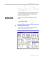
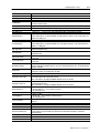
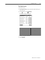
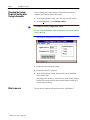
Configuring the Loops
In this field:
Run Setpoint
Standby Setpoint
Manual Output Value
SP Ramp Rate
SP Ramp Enable
Max. M Limit
Min. M Limit
Heat TPO Period
Heat Min. On Time
Cool TPO Period
Cool Min. On Time
High Temp Alarm
Low Temp Alarm
High Deviation Alarm
Low Deviation Alarm
Dead Band for Alarms
C Alarm Rate
Temperature Sensor Type
Temperature Sensor Filter
Temperature Sensor TC
5–9
Enter this value:
0.0 thru 3276.7°
0.0 thru 3276.7°
-100.00 thru +100.00
0.00 thru 99.99°/min If enabled, the rate at which the current set point is increased or decreased to
reach the selected set point.
Toggles between enable and disable
-100.00 thru +100.00% The maximum M percentage allowable.
-100.00 thru +100.00% The minimum M percentage allowable.
0 thru 100.00s The period in seconds at which the heat bit is cycled and the M is updated.
0 thru 100.00s The minimum time in seconds for which the heat bit is turned on during the TPO period.
If the calculated time is less than this minimum, the heat bit will not be turned on. This on time must be less
than the heat TPO period.
0 thru 100.00s The period in seconds at which the cool bit is cycled and the M is updated.
0 thru 100.00s The minimum time in seconds for which the cool bit is turned on during the TPO period.
If the calculated time is less than this minimum, the cool bit will not be turned on. This on time must be less
than the cool TPO period.
-3276.8 thru 3276.7° A temperature value at the high end of the sensor limit, but still below the
maximum temperature value.
-3276.8 thru 3276.7° A temperature value at the low end of the sensor limit, but still above the minimum
temperature value.
-3276.8 thru 3276.7° A value that specifies the greatest deviation above the set point that the process
can tolerate.
-3276.8 thru 3276.7° A value that specifies the greatest deviation below the set point that the process
can tolerate.
0.0 thru 10.0° Once the temperature alarm bits are on, they are kept on until the temperature drops
below the high alarm point by this value rises above the low alarm point by this value. The deadband value
applies to all alarms.
-3276.8 thru 3276.7°/s If the rate of temperature (C) increase is greater than this value, the C rate alarm
is triggered. A value of 0.0 disables the C rate alarm.
mV, B, E, J, K, R, S, T
When enabled, the C input is passed through a first order step equivalent lag filter. The filter's time constant
is determined by the value entered in the TC field.
Note: This feature is only supported in Module Firmware Version 3.3 and later.
This is the filter time constant for the C input filter, and can range from 0.0 to 9.9 seconds. A setting of 0.0
effectively disables the filter.
Note: This feature is only supported in Module Firmware Version 3.3 and later.
Open Circuit Action
• Disable Loop (M=0)
• M = On Break M value The forced M value on TC break.
• M = Manual Output value
Open Circuit M Value
-100.00 thru +100.00 The percentage value to force into the M output when a broken TC is detected.
TIL Configuration
• Disable Loop (M=0)
• M = On TIL M The forced M value on thermal integrity loss.
• M = Manual Output value
TIL Forced M Value
TIL Period
TIL Temp. Change
Auto / Manual
Desired System Response
Control Type
Zone
Control Action
-100.00 thru +100.00 The percentage value to force into the M output when thermal integrity loss is
detected.
0 thru 100 minutes
0 thru 100°
Auto or Manual
Slow, Medium, Fast, or Very Fast The system response desired as a result of autotuning. This
selection will be used together with system parameter measured during autotuning to generate the
autotuning gains.
Barrel or NonBarrel
Inner or Outer
E=SP-C or E=C-SP
Publication 17716.4.5 - January 1997